thermostatic control valve - amotthermostatic control valve model r ...
TRANSCRIPT

Thermostatic Control ValveModel R
www.amot.comDatasheet_R_Thermostatic_Control_Valve_MAY18_Rev4 Page 1
Typical applications• Refrigeration compressors
• Industrial compressors
• Turbines
• Engines
• Gear boxes
• High pressure applications
Key benefits• No leak design
- No external moving parts
- No external dynamic seals
• Easily removable elements
• Environmentally friendly
• Reliable performance
• Easy installation
- Operates in any mounting position
Key features• Flow rates of 3 - 82 m3/hr (13 - 360 US gpm)
• DN20 - DN80 (¾” - 3”) pipe sizes
• Welded connections
• Tamper-proof temperature settings from 35°C - 82°C (95°F - 180°F)
• Pressure ratings up to 35 bar (500 psi)
Model R
Accreditations available• PED Suitable for Group 1 & 2 liquids
(Ensure materials are compatible)
• ATEX II 2G TX X
• Complies with all relevant EU directives

Thermostatic Control Valve - Model R
Datasheet_R_Thermostatic_Control_Valve_MAY18_Rev4 Page 2
ContentsOverview ................................................................ 3
Applications ............................................................ 4
Valve Characteristics ................................................ 4
Pressure drop ................................................... 4
Flow coefficient ................................................. 5
Viscosity correction ............................................ 6
Viscosity correction curve ................................... 6
SAE oils viscosities ............................................ 6
Available versions .............................................. 7
Temperature and element characteristics .............. 7
Element type and seal material ........................... 7
How to Order .......................................................... 8
Specification ........................................................... 9
Weights .................................................................. 9
Valve Dimensions .................................................... 10
Maintenance and Service Parts .................................. 11
Ordering from Americas and Canada .................... 11
Service kits ................................................ 11
Service kit model number structure ............... 11
Ordering from Europe and Asia-PAC ..................... 11
Seal kits .................................................... 11
Element(s) ................................................. 11
Seal kit model number structure ................... 12
Element part number structure ..................... 12
Service parts .................................................... 13
Contact .................................................................. 14

Thermostatic Control Valve - Model R
Datasheet_R_Thermostatic_Control_Valve_MAY18_Rev4 Page 3
OverviewAMOT Model R thermostatic valves provide reliable control of fluid temperatures in cooling systems, heat recovery and many other temperature control applications.
They are also suitable for process control and industrial applications where fluids must be mixed or diverted depending upon temperature.
All AMOT internally sensed valves have positive 3-way action. This ensures that on process start up all of the flow is through the bypass line giving the fastest possible warm up time.
Operation and flow control is established by the temperature element, which constantly monitors and regulates the process fluid to the exact specified temperature setting.
When required the valve will positively shut off the bypass line to give full cooling.
A 3-way valve ensures constant volume flow in the system and gives no restriction during the warm up cycle, ensuring maximum performance. Where shut off is not required, bypass holes are available.
The temperature control power is created by the expansion of a wax/copper mixture which is highly sensitive to temperature changes.
Large forces are created by the warming/expansion of the mixture which in turn acts upon the sliding valve, thus regulating the flow.
The diagram opposite shows the valve actuation in diverting mode at start and cooling positions.
During operation the sliding valve constantly modulates for accurate temperature control.
The reliable rugged construction provides a unit sensitive to temperature variations, not easily disturbed by pressure changes and sudden surges, which maintains stable temperatures over a wide range of operating conditions.
Housing materials• Cast Steel
Seal materials• Buna N/Nitrile
• Viton
• Neoprene
Element materials• Electroless nickel, plated
brass and bronze
• Brass/bronze
LeakholesIn some applications, it is necessary to have leak holes drilled in the element to ensure a small flow between ports B and C. Leakholes are available in sizes ranging from 2 mm - 8 mm (5⁄64” - 5⁄16”).
Please refer to the Leakhole size (G) section of the valve selection table on page 8 to determine the hole size required for specific applications.
Temperature settingsA wide selection of element materials, seals and temperatures are available. Follow the equipment manufacturers’ guidelines for oil systems and for specific operating temperatures of cooling/heating systems.
Temperature settings are available from 35°C - 82°C (95°F - 180°F). Refer to the temperature and element characteristics table on page 7 for specific temperature settings. In general the temperature quoted is the nominal operating temperature in diverting mode on water systems.
For long life, AMOT valves should not be operated continuously at temperatures in excess of 14°C (25°F) of their maximum continuous rating. If this condition is anticipated then consult AMOT for suitable alternatives.
For mixing and oil circuits the temperature may be one to two degrees higher due to flow, viscosity and other system parameters.
Elements and seals are available in a variety of materials. These materials are suitable for most applications. Please contact AMOT for material compatibility information.

Thermostatic Control Valve - Model R
Datasheet_R_Thermostatic_Control_Valve_MAY18_Rev4 Page 4
- 0.05 0.10 0.15 0.20 0.25 0.30 0.35 0.40 0.45 0.50 0.55 0.60 0.65
2 4 6 8 10 12 14 16 18
SAE 40 Oil at 110°F SAE 20 Oil at 110°F WaterValve CharacteristicsPressure drop (Metric units)
Flow rate (m3/hr) - Water
Size
20 (¾”) 3 4 5 6 8 9 10 11
25 (1”) 3 4 6 7 9 10 12 13
40 (1 ½”) 4 6 8 10 12 14 16 18
50 (2”) 8 12 16 20 24 28 32 36
65 (2 ½”) 10 15 20 25 31 36 41 46
80 (3”) 16 24 32 40 47 55 63 71
Pre
ssu
re d
rop
(b
ar)
0.650.600.550.50
0.450.400.350.30
0.250.20
0.150.100.05
-
ApplicationsDiverting ApplicationsWhen valves are used for diverting services, the inlet is Port A (temperature sensing port), with Port C being connected to the cooler, and Port B connected to the cooler by-pass line.
Mixing ApplicationsWhen valves are used for mixing service, Port C is the cold fluid inlet port from the cooler, Port B is the hot by-pass fluid inlet, and Port A the common outlet. Port A is the temperature sensing port and will mix the hot and cold fluids in the correct proportion so as to produce the desired outlet temperature leaving Port A.
2-Way Water Saving ApplicationsValve as shown maintains minimum flow through cooler to conserve water. Requires internal leak hole to permit small flow for sensing.
Heat Load
ABC
AM
OT
Thermostat
Heat Removal Cooler
Pump
Heat Load
AB C
Heat Removal Cooler
Pump
AMOTThermostat
Heat Load
Pump
CA
B
Port Blocked
Heat Exchanger
AM
OT
Thermostat
AMOT thermostatic valves are designed to produce minimal pressure drop. The normal recommendation in sizing the valves is to select a pressure drop between 0.14 - 0.5 bar (2 - 7 psi).
WaterSAE 20 oil at 110°FSAE 40 oil at 110°F

Thermostatic Control Valve - Model R
Datasheet_R_Thermostatic_Control_Valve_MAY18_Rev4 Page 5
-
1
2
3
4
5
6
7
8
9
10
5 10 15 20 25 30 35 40 45
SAE 40 Oil at 110°F SAE 20 Oil at 110°F Water
Valve Characteristics Continued
Flow coefficientFlow coefficient (calculated)Size Kv Cv20 (¾”) 14 1625 (1”) 16 1840 (1 ½”) 22 2550 (2”) 44 5165 (2 ½”) 56 6580 (3”) 87 101
Kv = 0.865 Cv
Cv = 1.156 Kv
Pressure drop (English units)
Flow rate (US gpm) - Water
Size
20 (¾”) 6 10 13 16 19 22 26 29
25 (1”) 7 11 14 18 22 25 29 32
40 (1 ½”) 10 15 20 25 30 35 40 45
50 (2”) 20 31 41 51 61 71 82 92
65 (2 ½”) 26 39 52 65 78 91 104 117
80 (3”) 40 61 81 101 121 141 162 182
Pre
ssu
re d
rop
(p
si)
10
9
8
7
6
5
4
3
2
1
-
Kv is the flow coefficient in metric units. It is defined as the flow rate in cubic meters per hour (m3/hr) of water at a temperature of 16º Celsius with a pressure drop across the valve of 1 bar. The basic formula to find a valve’s Kv is shown below:
Cv is the imperial coefficient. It is defined as the flow rate in US Gallons per minute (gpm) of water at a temperature of 60º Fahrenheit with a pressure drop across the valve of 1 psi. The basic formula to find a valve’s Cv is shown below:
DPSGKv = Q
SGDPQ = Kv
KvDP = SG Q2
Q = Flow in m3/hrDP = Pressure drop (bar)SG = Specific gravity of fluid (Water = 1.0)Kv = Valve flow coefficient (Metric units)
DPSGCv = Q
SGDPQ = Cv
CvDP = SG Q2
Q = Flow in US Gallons/MinDP = Pressure drop (psi)SG = Specific gravity of fluid (Water = 1.0)Cv = Valve flow coefficient (English units)
AMOT thermostatic valves are designed to produce minimal pressure drop. The normal recommendation in sizing the valves is to select a pressure drop between 0.14 - 0.5 bar (2 - 7 psi).
WaterSAE 20 oil at 110°FSAE 40 oil at 110°F

Thermostatic Control Valve - Model R
Datasheet_R_Thermostatic_Control_Valve_MAY18_Rev4 Page 6
0.5
0.6
0.7
0.8
0.9
1
1 10 100 1000
Valve Characteristics ContinuedViscosity correctionFor the selection of valves for use with more viscous fluids than water, the following must be calculated in addition to using the previously mentioned formulae:
• Viscosity
Find the viscosity of the fluid to be used in the valve. This will generally be in centistokes (cST).
ISO grade oil is easy to calculate as the grade no. is the viscosity. I.e. ISO VG 46 = 46 centistokes at 43°C (110°F)
• Viscosity correction
Once the viscosity value has been found, the flow coefficient correction factor can be established using the viscosity correction graph below.
The correction value (Fv) that is produced by the graph should then be multiplied by the original flow coefficient. This gives the corrected flow coefficient, which can then be used in the standard formula.
e.g.: 100 cST = correction factor of 0.68 0.68 x flow co. = corrected flow co. (Kv or Cv)
Viscosity correction curve (Fv)
SAE oils viscositiesEngine oilsOil cST
SAE 5W 6.8
SAE 10W 32
SAE 20 46
SAE 20W 68
SAE 30 100
SAE 40 150
SAE 50 220
6 B 394
8 B 571
Gear oilsOil cST
SAE 75W 22
SAE 80W 46
SAE 85W 100
SAE 90 150
SAE 140 460
Approximate viscosities of SAE oils at 43°C (110°F) (cST).
Based on leading oil manufacturers’ published data.
Cor
rect
ion
val
ue
(Fv)
1.0
0.9
0.8
0.7
0.6
0.51 10 100 1000
Viscosity (Centistokes [cST])

Thermostatic Control Valve - Model R
Datasheet_R_Thermostatic_Control_Valve_MAY18_Rev4 Page 7
Temperature and element characteristics
CodeControl temp.
Temperature range Max temp. cont.20 - 40 mm (¾” - 1 ½”)
50 - 80 mm (2” - 3”)
20 - 40 mm (¾” - 1 ½”)
50 - 80 mm (2” - 3”)
°C °F °C °F °C °F °C °F °C °F095 35 95 30-40 86-104 29-41 84-105 50 122 49 120100 38 100 33-42 91-108 34-42 93-108 75 167 50 122110 43 110 38-47 100-117 38-47 100-117 82 180 56 133120 49 120 43-55 109-131 43-54 109-129 88 191 66 150130 54 130 49-60 120-140 51-60 124-140 95 203 68 158140 60 140 54-65 129-149 57-66 135-151 99 210 74 165150 66 150 60-71 140-160 63-72 145-162 100 212 82 180160 71 160 65-76 149-169 68-78 154-172 100 212 88 190170 77 170 73-82 163-180 74-83 165-181 100 212 93 200175 79 175 77-85 171-185 77-85 171-185 105 221 102 215180 82 180 79-88 174-190 79-88 174-190 110 231 104 220
Element type and seal material
Valve Characteristics ContinuedAvailable versions
CodeElement type
Element construction
Seal materialRO20 - 40
RO50 - 65RO80
USA/Canada Europe/Asia-PAC01
5435X 21376X 46856X 1096X Standard
Buna N/Nitrile
02 Viton
03 Neoprene
04
5435P 21376P 46856P 1096P Electroless nickel
Buna N/Nitrile
05 Viton
06 Neoprene
Valve size (B) - mm (inches)
Port connection (D)Butt Weld DIN 2448 PN40 (X)
Socket Weld ANSI B16.11 (Y)
Butt Weld ANSI B36.10 SCH.40 (Z)
20 (¾”) 25 (1”)
40 (1 ½”) 50 (2”)
65 (2 ½”) 80 (3”)

Thermostatic Control Valve - Model R
Datasheet_R_Thermostatic_Control_Valve_MAY18_Rev4 Page 8
How to Order
Example RO 40 S X 110 03 4 -AA Code description CommentsValve model (A)
Valve model (A) RO StandardValve size (B) - mm (inches)
Valve size (B)
20 20 (¾”) 1 Element25 25 (1”) 1 Element40 40 (1 ½”) 1 Element50 50 (2”) 1 Element65 65 (2 ½”) 1 Element80 80 (3”) 2 Elements
Body Material (C)Body material (C) S Cast steel
Port connection (D)
Port connection (D)X Butt Weld DIN 2448 PN40 20-80 mmY Socket Weld ANSI 16.11 20-65 mmZ Butt Weld ANSI B36.10 SCH.40 20-50 mm
Control temperature °F (E)
Control temperature °F (E) *For temperatures available, refer to the temperature and element characteristics table on page 7.Element and seal material (F)
Element and seal material (F) ** For element/seal materials available, refer to the element type and seal material table on page 7.Leakhole size (G) - mm (inches) Leakhole diameter between ports B & C
Leakhole size (G)
0 None2 2 (5⁄64”)3 3 (1⁄8”)4 4 (5⁄32”)5 5 (13⁄64”)6 6 (1⁄4”)8 8 (5⁄16”)
Customer special requirements (H)
Customer special requirements (H)Standard
-*** Customer special code
Use the table below to select the unique specification of your Model R Thermostatic Control Valve.

Thermostatic Control Valve - Model R
Datasheet_R_Thermostatic_Control_Valve_MAY18_Rev4 Page 9
SpecificationMetric units English units
Flow rate 3 - 82 m3/hr 13 - 360 gpm
Body material Cast steel BS 3146 CLA 1A-ASTM A216 WCB-DIN 17245 Grade 1.0169 (GSC 25N)
Seal materials Buna N/Nitrile, Viton, and Neoprene
Mounting position Any orientation
Welded port connectionsButt Weld DIN 2448 PN40 20 - 80 mm ¾” - 3”
Butt Weld ANSI B36.10 SCH.40 20 - 50 mm ¾” - 2”
Socket Weld ANSI B16.11 20 - 65 mm ¾” - 2 ½”
Valve sizes (nominal bore) 20 - 80 mm ¾” - 3”
Recommended pressure drop 0.14 - 0.5 bar 2 - 7 psi
Control temperatures 35°C - 82°C 95°F - 180°F
Maximum working pressure 35 bar 500 psi
Accreditations available
PED Suitable for Group 1 & 2 liquids. Ensure materials are compatible.
ATEX II 2G TX X
Complies with all relevant EU directives
Port connection (D)Valve size (B) - mm (inches)
20 (¾”) 25 (1”) 40 (1 ½”) 50 (2”) 65 (2 ½”) 80 (3”)Butt Weld DIN 2448 PN40 (X) 3.2 (7) 3.2 (7) 3.5 (8) 7 (15) 7 (15) 17.5 (39)Socket Weld ANSI B16.11 (Y) 3.5 (8) 3.5 (8) 4 (9) 7.5 (16) 7.5 (16) N/A
Butt Weld ANSI B36.10 SCH.40 (Z) 3.2 (7) 3.2 (7) 3.5 (8) 7 (15) N/A N/A
WeightsApproximate weights in kg (lbs)

Thermostatic Control Valve - Model R
Datasheet_R_Thermostatic_Control_Valve_MAY18_Rev4 Page 10
Valve DimensionsDimensions - mm (inches)
General dimensions
Dimensions
Nominal bore size
20 - 40 mm (¾” - 1 ½”)
50 - 80 mm (2” - 3”)
Butt Socket Butt Socket
A 85 (3.35”)
95 (3.74”)
100 (3.94”)
110 (4.33”)
B 105 (4.13”)
115 (4.53”)
132 (5.20”)
142 (5.59”)
C 52 (2.05”)
52 (2.05”)
64 (2.52”)
64 (2.52”)
D 102 (4.02”)
102 (4.02”)
123 (4.84”)
123 (4.84”)
Butt Weld DIN 2448 PN40 (X)Nominal bore size
mm (inches)
20 (¾”)
25 (1”)
40 (1 ½”)
50 (2”)
65 (2 ½”)
80 (3”)
ØE 22.3 (0.88”)
28.5 (1.12”)
43.1 (1.70”)
54.5 (2.15”)
70.3 (2.77”)
78 (3.07”)
ØF 27 (1.06”)
34 (1.34”)
48 (1.89”)
60 (2.36”)
76 (2.99”)
89 (3.50”)
Butt Weld ANSI B36.10 SCH.40 (Z)Nominal bore size
mm (inches)
20 (¾”)
25 (1”)
40 (1 ½”)
50 (2”)
65 (2 ½”)
80 (3”)
ØE 20.9 (0.82”)
26.6 (1.05”)
40.9 (1.61”)
52.5 (2.07”) N/A N/A
ØF 27 (1.06”)
34 (1.34”)
48 (1.89”)
60 (2.36”) N/A N/A
Socket Weld ANSI B16.11 (Y)Nominal bore size
mm (inches)
20 (¾”)
25 (1”)
40 (1 ½”)
50 (2”)
65 (2 ½”)
80 (3”)
ØE 20 (0.75”)
25 (1.00”)
40 (1.50”)
50 (2.00”)
65 (2.50”) N/A
ØF 38 (1.50”)
46 (1.81”)
62 (2.44”)
74 (2.91”)
92 (3.62”) N/A
G 13 (0.51”)
13 (0.51”)
13 (0.51”)
16 (0.63”)
16 (0.63”) N/A
ØH 27.2 (1.07”)
33.9 (1.33”)
48.8 (1.92”)
61.2 (2.41”)
74 (2.91”) N/A
A
B C
AM
OT C
ON
TRO
LS
ALLOW 75mm ABOVE COVER TO REMOVE ELEMENT
AMOT
SOCKET WELD END CONNECTION

Thermostatic Control Valve - Model R
Datasheet_R_Thermostatic_Control_Valve_MAY18_Rev4 Page 11
Service kit model number structure1) Replace Body material (C) and Port connection
(D) with “KIT-”.
2) If Special (H) is not blank, please contact the facility.
Example valve part numberA B C D E F G H
RO 25 S X 120 01 0
Example service kit model numberA B C D E F G H
RO 25 KIT- 120 01 0A - Valve model E - Control temperature (°F)B - Valve size F - Element and seal materialC - Body material G - Leakhole sizeD - Port connection H - Special
Maintenance and Service PartsOver time, exposure to foreign chemicals and particulate matter as well as prolonged operation at extreme conditions may reduce the effectiveness of the control valve. At such time, AMOT Thermostatic Valves can be restored to original performance by installing an AMOT thermostatic valve service kit or a seal kit and new temperature element.
Service kits are ONLY available for purchase from the Americas and Canada locations. If ordering from the Europe or Asia-PAC locations please purchase a seal kit and element to properly service your valve.
Service kits include all new seals and thermostatic element required for normal maintenance. Seal kits include new seals only. Whenever elements are replaced, the seals should also be replaced.
AMOT recommends fully servicing thermostatic control valves with each regularly scheduled major overhaul of the turbine, engine, compressor or other associated equipment. AMOT recommends a service interval of not more than 24 months to ensure optimum valve performance.
AMOT designs and tests all its products to ensure that high quality standards are met. For good product life, carefully follow AMOT’s installation and maintenance instructions; failure to do so could result in damage to the equipment being protected or controlled. Thermostatic service kits may also be used for adapting valves to new service temperatures. Please request a new nameplate when adapting valves to a new service temperature by contacting the facility.
Ordering from Americas and Canada
Service kits are ONLY available for purchase from the Americas and Canada locations.
Service kits are available with element and seals required to service the valve. Order service kits using the AMOT valve part number and nominal temperature setting. Refer to the AMOT valve part number that is printed on the valve nameplate and the AMOT valve part number structure on page 8. The nominal temperature setting is also stamped onto the element flange.
AMOT does NOT offer service kits for 3” RO (RO80) Model R Thermostatic Valves. In order to properly service a 3” RO valve please purchase an element and seal kit. Refer to the ordering instructions on page 12.
Ordering from Europe and Asia-PACSeal kits
Seal kits are available with seals only. Order seal kits using the basic seal kit model number, valve size, and element/seal material code from the AMOT valve part number. Refer to the AMOT valve part number that is printed on the valve nameplate and the AMOT valve part number structure on page 8.
Element(s)
Order temperature elements using the element part number which is identified by the valve size, element/seal material code and nominal temperature setting from the AMOT valve part number. Refer to the AMOT valve part number that is printed on the valve nameplate and the AMOT valve part number structure on page 8.
Service kits

Thermostatic Control Valve - Model R
Datasheet_R_Thermostatic_Control_Valve_MAY18_Rev4 Page 12
Maintenance and Service Parts Continued
Seal kit model number structure1) Identify the valve size, located in the Valve size
(B) section of the AMOT valve part number. Use that value to identify the corresponding basic model number in Table 1.
2) Identify the element/seal material code, located in the Element and seal material (F) section of the AMOT valve part number. Use that value to identify the corresponding seal code in Table 2.
3) Place the seal code after “X1” in the basic model number to complete the seal kit model number, as shown in Table 3.
Table 1 - Basic model number identificationBasic
model no. Valve size (B)1
46857X1 20, 25, 40
46858X1 50, 65
80660X1 80
Table 2 - Seal code identification
Seal code
Element/seal material (F)2
01 01, 04
02 02, 05
03 03, 06
Table 3 - Seal kit identificationBasic model no.
(Table 1)Seal code (Table 2)
46857X1
01, 02, 0346858X1
80660X1
ExamplesValve part number Seal kit model number
RO25SX120010 46857X1 01
RO65SY130060 46858X1 03
RO80SZ130050 80660X1 02
Table 4 - Element part number identificationValve
size (B)1 Temperature °F (E) Element/seal material (F)2 Element part number Qty. Comments
20, 25, 40
095-180
01, 02, 03
5435X(Temp.)
150, 65
21376X(Temp.) USA/Canada ONLY
46856X(Temp.) Europe/Asia-PAC ONLY
80 1096X(Temp.) 2
20, 25, 40
04, 05, 06
5435P(Temp.)
150, 65
21376P(Temp.) USA/Canada ONLY
46856P(Temp.) Europe/Asia-PAC ONLY
80 1096P(Temp.) 2
ExamplesValve part number Element part number Qty. Comments
RO 50 S X 095 06 0 46856P095 1
RO 80 S X 150 03 0 1096X150 2
Element part number structure1) Identify the valve size, located in the Valve size
(B) section of the AMOT valve part number. Two examples are shown in Table 4.
2) Identify the element/seal material code, located in the Element and seal material (F) section of the AMOT valve part number.
3) Identify the temperature, located in the Control temperature °F (E) section of the AMOT valve part number.
4) Use those 3 codes in Table 4 to identify the proper element part number.
NOTES:1 If your valve size code does not correspond with the given values, please contact the facility to confirm your valve size code.2 If your element/seal material code does not correspond with the given values, please contact the facility to confirm your element/seal material code.
Ordering from Europe and Asia-PAC continued
Thermostatic Control Valve - Model R
Datasheet_R_Thermostatic_Control_Valve_MAY18_Rev4 Page 13
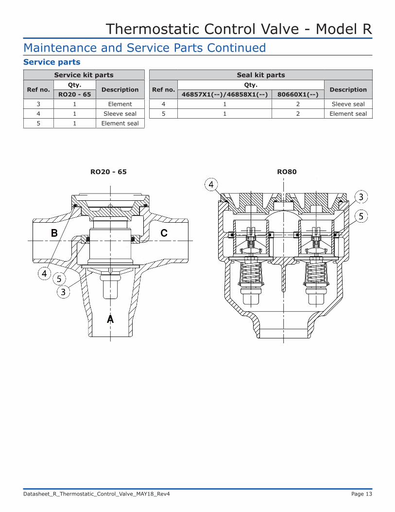
Service partsService kit parts
Ref no.Qty.
DescriptionRO20 - 65
3 1 Element4 1 Sleeve seal5 1 Element seal
Seal kit parts
Ref no.Qty.
Description46857X1(--)/46858X1(--) 80660X1(--)
4 1 2 Sleeve seal5 1 2 Element seal
Maintenance and Service Parts Continued
RO20 - 65 RO80

Thermostatic Control Valve - Model R
Datasheet_R_Thermostatic_Control_Valve_MAY18_Rev4 Page 14
Contact
Americas Europe, Middle East and Africa
AMOT USA8824 Fallbrook Dr.Houston, TX 77064USA
Tel: +1 (281) 940 1800Fax: +1 (713) 559 9419Email: [email protected]
AMOT UKWestern WayBury St. EdmundsSuffolk, IP33 3SZEngland
Tel: +44 1284 715739Fax: +44 1284 760256Email: [email protected]
AMOT GermanyRondenbarg 2522525 HamburgGermany
Tel: +49 40 8537 1298Fax: +49 40 8537 1331Email: [email protected] Pacific
AMOT ShanghaiBd. 7A, No. 568, Longpan Rd., Malu JiadingShanghai 201801China
Tel: +86 21 5910 4052Fax: +86 21 5237 8560Email: [email protected]
www.amot.com