thermostatic control valve - amot.com · thermostatic control valve - model c datasheet c...
TRANSCRIPT
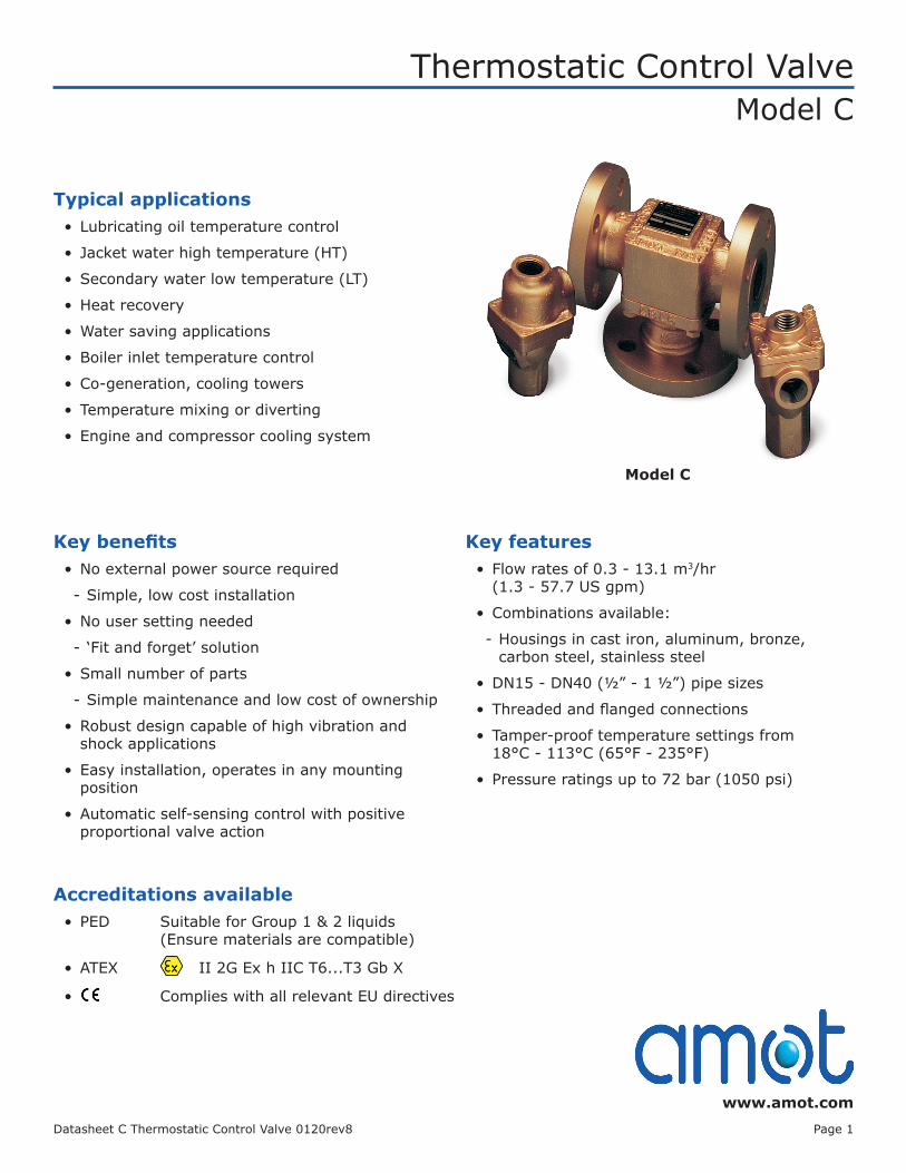
Thermostatic Control ValveModel C
www.amot.comDatasheet C Thermostatic Control Valve 0120rev8 Page 1
Typical applications• Lubricating oil temperature control
• Jacket water high temperature (HT)
• Secondary water low temperature (LT)
• Heat recovery
• Water saving applications
• Boiler inlet temperature control
• Co-generation, cooling towers
• Temperature mixing or diverting
• Engine and compressor cooling system
Key benefits• No external power source required
- Simple, low cost installation
• No user setting needed
- ‘Fit and forget’ solution
• Small number of parts
- Simple maintenance and low cost of ownership
• Robust design capable of high vibration and shock applications
• Easy installation, operates in any mounting position
• Automatic self-sensing control with positive proportional valve action
Key features• Flow rates of 0.3 - 13.1 m3/hr
(1.3 - 57.7 US gpm)
• Combinations available:
- Housings in cast iron, aluminum, bronze, carbon steel, stainless steel
• DN15 - DN40 (½” - 1 ½”) pipe sizes
• Threaded and flanged connections
• Tamper-proof temperature settings from 18°C - 113°C (65°F - 235°F)
• Pressure ratings up to 72 bar (1050 psi)
Model C
Accreditations available• PED Suitable for Group 1 & 2 liquids
(Ensure materials are compatible)
• ATEX II 2G Ex h IIC T6...T3 Gb X
• Complies with all relevant EU directives
Thermostatic Control Valve - Model C
Datasheet C Thermostatic Control Valve 0120rev8 Page 2
ContentsOverview ................................................................ 3
Applications ............................................................ 4
Valve Characteristics ................................................ 4
Pressure drop ................................................... 4
Flow coefficient ................................................. 5
Viscosity correction ............................................ 6
Viscosity correction curve ................................... 6
SAE oils viscosities ............................................ 6
Available versions .............................................. 7
Temperature and element characteristics .............. 7
Element type and seal material ........................... 7
How to Order .......................................................... 8
Specification ........................................................... 9
Weights .................................................................. 9
Valve Dimensions .................................................... 10
Maintenance and Service Parts .................................. 11
Ordering from Americas and Canada .................... 11
Service kits ................................................ 11
Service kit model number structure ............... 11
Ordering from Europe and Asia-PAC ..................... 11
Seal kits .................................................... 11
Element(s) ................................................. 11
Seal kit model number structure ................... 12
Element part number structure ..................... 12
Service parts .................................................... 13
Contact .................................................................. 14
Thermostatic Control Valve - Model C
Datasheet C Thermostatic Control Valve 0120rev8 Page 3
OverviewAMOT Model C thermostatic valves are available in a wide selection of sizes and settings to fill a multitude of fluid temperature control requirements. These valves may be mounted in any position and use the proven expanding wax principle to actuate the 3-way temperature element assemblies. The model C valves may be used for diverting or mixing service.
They make very economical temperature limiting valves to prevent scalding in hot water supply systems; such as in emergency water systems for labs. Radiant heating systems can use these valves in limiting water temperature to prevent surface cracking and over-heating of plastic piping. Other applications include electronic and battery cooling circuits, pump temperature relief valves etc.
Temperature settingsA wide selection of element materials, seals and temperatures are available. Follow the equipment manufacturers’ guidelines for heating/cooling systems.
Temperature settings are available from 18°C - 113°C (65°F - 235°F). Refer to the temperature and element characteristics table on page 7 for specific temperature settings. In general the temperature quoted is the nominal operating temperature in diverting mode on water systems.
For long life, AMOT valves should not be operated continuously at temperatures in excess of 14°C (25°F) of their maximum continuous rating. If this condition is anticipated then consult AMOT for suitable alternatives.
For mixing and oil circuits the temperature may be one to two degrees higher due to flow, viscosity and other system parameters.
Elements and seals are available in a variety of materials. These materials are suitable for most applications. Please contact AMOT for material compatibility information.
Housing materials• Cast iron
• Aluminum
• Bronze
• Steel
• Stainless steel
Seal materials• Buna N/Nitrile
• Viton
• Neoprene
Element materials• Bronze, brass and stainless
steel
• Nickel plated/stainless steel
• Stainless steel
LeakholesIn some applications, it is necessary to have leak holes drilled in the element to ensure a small flow between ports A and C. Leak holes are available in sizes ranging from 0.8 mm - 6.3 mm (1⁄32” - 1⁄4”).
Please refer to the Leakhole size (G) section of the valve selection table on page 8 to determine the hole size required for specific applications.
Thermostatic Control Valve - Model C
Datasheet C Thermostatic Control Valve 0120rev8 Page 4
- 0.05 0.10 0.15 0.20 0.25 0.30 0.35 0.40 0.45 0.50 0.55 0.60 0.65
0.9 1.5 2.1 2.7 3.3 3.9 4.5
SAE 40 Oil at 110°F SAE 20 Oil at 110°F Water
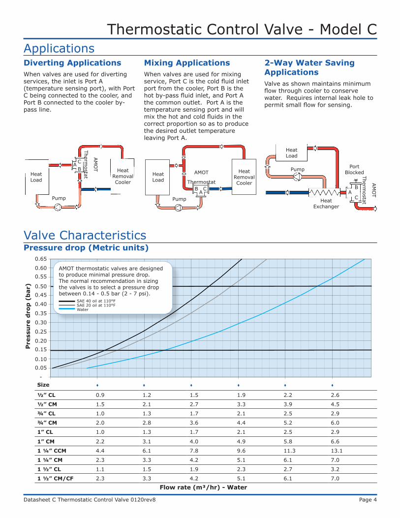
ApplicationsDiverting ApplicationsWhen valves are used for diverting services, the inlet is Port A (temperature sensing port), with Port C being connected to the cooler, and Port B connected to the cooler by-pass line.
Pressure drop (Metric units)
Mixing ApplicationsWhen valves are used for mixing service, Port C is the cold fluid inlet port from the cooler, Port B is the hot by-pass fluid inlet, and Port A the common outlet. Port A is the temperature sensing port and will mix the hot and cold fluids in the correct proportion so as to produce the desired outlet temperature leaving Port A.
2-Way Water Saving ApplicationsValve as shown maintains minimum flow through cooler to conserve water. Requires internal leak hole to permit small flow for sensing.
Heat Load
ABC
AM
OT
Thermostat
Heat Removal Cooler
Pump
Heat Load
AB C
Heat Removal Cooler
Pump
AMOT
Thermostat
Heat Load
Pump
CA
B
Port Blocked
Valve Characteristics
Heat Exchanger
AM
OT
Thermostat
Flow rate (m³/hr) - Water
Size
½” CL 0.9 1.2 1.5 1.9 2.2 2.6
½” CM 1.5 2.1 2.7 3.3 3.9 4.5
¾” CL 1.0 1.3 1.7 2.1 2.5 2.9
¾” CM 2.0 2.8 3.6 4.4 5.2 6.0
1” CL 1.0 1.3 1.7 2.1 2.5 2.9
1” CM 2.2 3.1 4.0 4.9 5.8 6.6
1 ¼” CCM 4.4 6.1 7.8 9.6 11.3 13.1
1 ¼” CM 2.3 3.3 4.2 5.1 6.1 7.0
1 ½” CL 1.1 1.5 1.9 2.3 2.7 3.2
1 ½” CM/CF 2.3 3.3 4.2 5.1 6.1 7.0
0.65
0.600.55
0.500.45
0.40
0.35
0.30
0.25
0.200.15
0.100.05
-
Pre
ssu
re d
rop
(b
ar)
AMOT thermostatic valves are designed to produce minimal pressure drop. The normal recommendation in sizing the valves is to select a pressure drop between 0.14 - 0.5 bar (2 - 7 psi).
WaterSAE 20 oil at 110°FSAE 40 oil at 110°F
Thermostatic Control Valve - Model C
Datasheet C Thermostatic Control Valve 0120rev8 Page 5
-
1
2
3
4
5
6
7
8
9
10
0 3 6 9 12 15 18 21 24
SAE 40 Oil at 110°F SAE 20 Oil at 110°F Water
Size
½” CL 1.7 3.4 5.1 6.9 8.6 10.3 12.0
½” CM 3.0 6.0 9.0 12.0 15.0 18.0 21.0
¾” CL 1.9 3.9 5.8 7.7 9.6 11.6 13.5
¾” CM 4.1 8.1 12.2 16.3 20.4 24.4 28.5
1” CL 1.9 3.9 5.8 7.7 9.6 11.6 13.5
1” CM 4.5 8.9 13.4 17.8 22.3 26.7 31.2
1 ¼” CCM 8.8 17.6 26.4 35.1 43.9 52.7 61.5
1 ¼” CM 4.7 9.4 14.1 18.9 23.6 28.3 33.0
1 ½” CL 2.1 4.3 6.4 8.6 10.7 12.9 15.0
1 ½” CM/CF 4.7 9.4 14.1 18.9 23.6 28.3 33.0
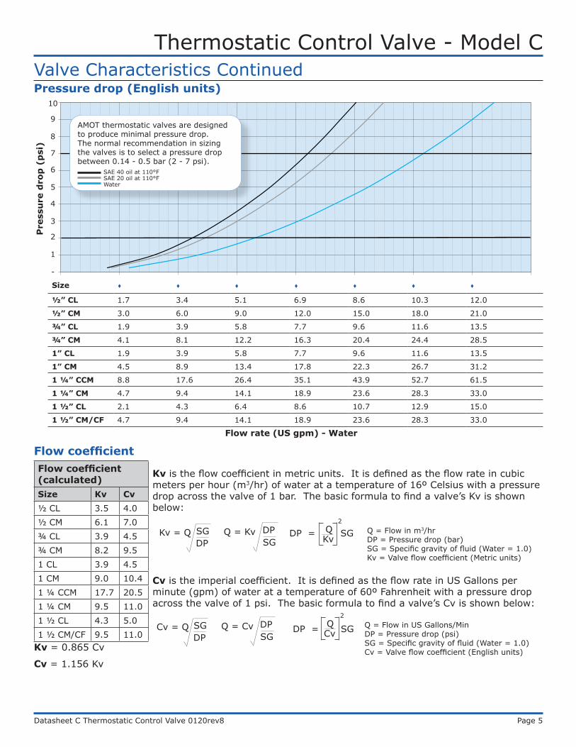
Valve Characteristics Continued
Flow coefficientFlow coefficient (calculated)Size Kv Cv½ CL 3.5 4.0½ CM 6.1 7.0¾ CL 3.9 4.5¾ CM 8.2 9.51 CL 3.9 4.51 CM 9.0 10.41 ¼ CCM 17.7 20.51 ¼ CM 9.5 11.01 ½ CL 4.3 5.01 ½ CM/CF 9.5 11.0
Kv is the flow coefficient in metric units. It is defined as the flow rate in cubic meters per hour (m3/hr) of water at a temperature of 16º Celsius with a pressure drop across the valve of 1 bar. The basic formula to find a valve’s Kv is shown below:
Kv = 0.865 Cv
Cv = 1.156 Kv
Cv is the imperial coefficient. It is defined as the flow rate in US Gallons per minute (gpm) of water at a temperature of 60º Fahrenheit with a pressure drop across the valve of 1 psi. The basic formula to find a valve’s Cv is shown below:
DPSGKv = Q
SGDPQ = Kv
KvDP = SG Q2
Q = Flow in m3/hrDP = Pressure drop (bar)SG = Specific gravity of fluid (Water = 1.0)Kv = Valve flow coefficient (Metric units)
DPSGCv = Q
SGDPQ = Cv
CvDP = SG Q2
Q = Flow in US Gallons/MinDP = Pressure drop (psi)SG = Specific gravity of fluid (Water = 1.0)Cv = Valve flow coefficient (English units)
Pressure drop (English units)
Flow rate (US gpm) - Water
Pre
ssu
re d
rop
(p
si)
10
9
8
7
6
5
4
3
2
1
-
AMOT thermostatic valves are designed to produce minimal pressure drop. The normal recommendation in sizing the valves is to select a pressure drop between 0.14 - 0.5 bar (2 - 7 psi).
WaterSAE 20 oil at 110°FSAE 40 oil at 110°F
Thermostatic Control Valve - Model C
Datasheet C Thermostatic Control Valve 0120rev8 Page 6
0.5
0.6
0.7
0.8
0.9
1
1 10 100 1000
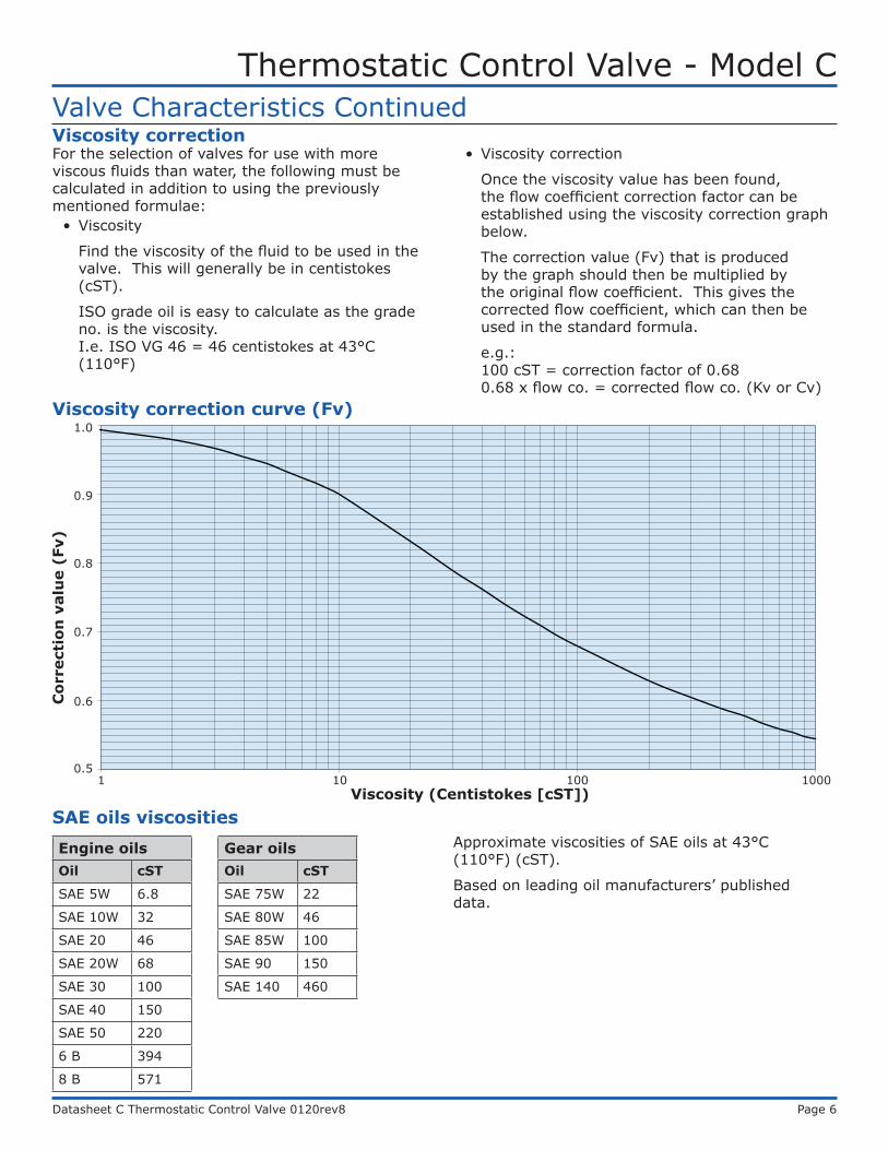
Valve Characteristics ContinuedViscosity correctionFor the selection of valves for use with more viscous fluids than water, the following must be calculated in addition to using the previously mentioned formulae:
• Viscosity
Find the viscosity of the fluid to be used in the valve. This will generally be in centistokes (cST).
ISO grade oil is easy to calculate as the grade no. is the viscosity. I.e. ISO VG 46 = 46 centistokes at 43°C (110°F)
• Viscosity correction
Once the viscosity value has been found, the flow coefficient correction factor can be established using the viscosity correction graph below.
The correction value (Fv) that is produced by the graph should then be multiplied by the original flow coefficient. This gives the corrected flow coefficient, which can then be used in the standard formula.
e.g.: 100 cST = correction factor of 0.68 0.68 x flow co. = corrected flow co. (Kv or Cv)
Viscosity correction curve (Fv)
SAE oils viscositiesEngine oilsOil cST
SAE 5W 6.8
SAE 10W 32
SAE 20 46
SAE 20W 68
SAE 30 100
SAE 40 150
SAE 50 220
6 B 394
8 B 571
Gear oilsOil cST
SAE 75W 22
SAE 80W 46
SAE 85W 100
SAE 90 150
SAE 140 460
Approximate viscosities of SAE oils at 43°C (110°F) (cST).
Based on leading oil manufacturers’ published data.
Cor
rect
ion
val
ue
(Fv)
1.0
0.9
0.8
0.7
0.6
0.51 10 100 1000
Viscosity (Centistokes [cST])
Thermostatic Control Valve - Model C
Datasheet C Thermostatic Control Valve 0120rev8 Page 7
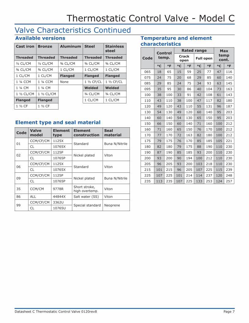
Temperature and element characteristics
CodeControl temp.
Rated range Max temp cont.
Crack open Full open
°C °F °C °F °C °F °C °F
065 18 65 15 59 25 77 47 116
075 24 75 20 68 29 85 60 140
085 29 85 24 75 34 93 63 145
095 35 95 30 86 40 104 73 163
100 38 100 33 91 42 108 61 143
110 43 110 38 100 47 117 82 180
120 49 120 43 110 55 131 96 187
130 54 130 49 120 60 140 95 203
140 60 140 54 130 65 150 95 203
150 66 150 60 140 71 160 100 212
160 71 160 65 150 76 170 100 212
170 77 170 72 163 82 180 100 212
175 79 175 76 170 85 185 105 221
180 82 180 79 175 88 190 110 230
190 87 190 85 185 93 200 110 230
200 93 200 90 194 100 212 110 230
205 96 205 93 200 103 218 110 230
215 101 215 96 205 107 225 115 239
225 107 225 101 214 114 237 120 248
235 113 235 107 225 133 253 124 257
Code Valve model
Element type
Element construction
Seal material
01CCM/CF/CM 1125X
Standard Buna N/NitrileCL 10765X
02CCM/CF/CM 1125P
Nickel plated VitonCL 10765P
06CCM/CF/CM 1125X
Standard VitonCL 10765X
09CCM/CF/CM 1125P
Nickel plated Buna N/NitrileCL 10765P
35 CCM/CM 9778R Short stroke, high overtemp. Viton
86 ALL 44844X Salt water (SS) Viton
99CCM/CF/CM 3362U
Special standard NeopreneCL 10765U
Element type and seal material
Valve Characteristics Continued
Cast iron Bronze Aluminum Steel Stainless steel
Threaded Threaded Threaded Threaded Threaded
½ CL/CM ½ CL/CM ¾ CL/CM ¾ CL/CM ¾ CL/CM
¾ CL/CM ¾ CL/CM 1 CL/CM 1 CL/CM 1 CL/CM
1 CL/CM 1 CL/CM Flanged Flanged Flanged
1 ¼ CCM 1 ¼ CCM None 1 ½ CF/CL 1 ½ CF/CL
1 ¼ CM 1 ¼ CM Welded Welded
1 ½ CL/CM 1 ½ CL/CM ¾ CL/CM ¾ CL/CM
Flanged Flanged 1 CL/CM 1 CL/CM
1 ½ CF 1 ½ CF
Available versions
Thermostatic Control Valve - Model C
Datasheet C Thermostatic Control Valve 0120rev8 Page 8
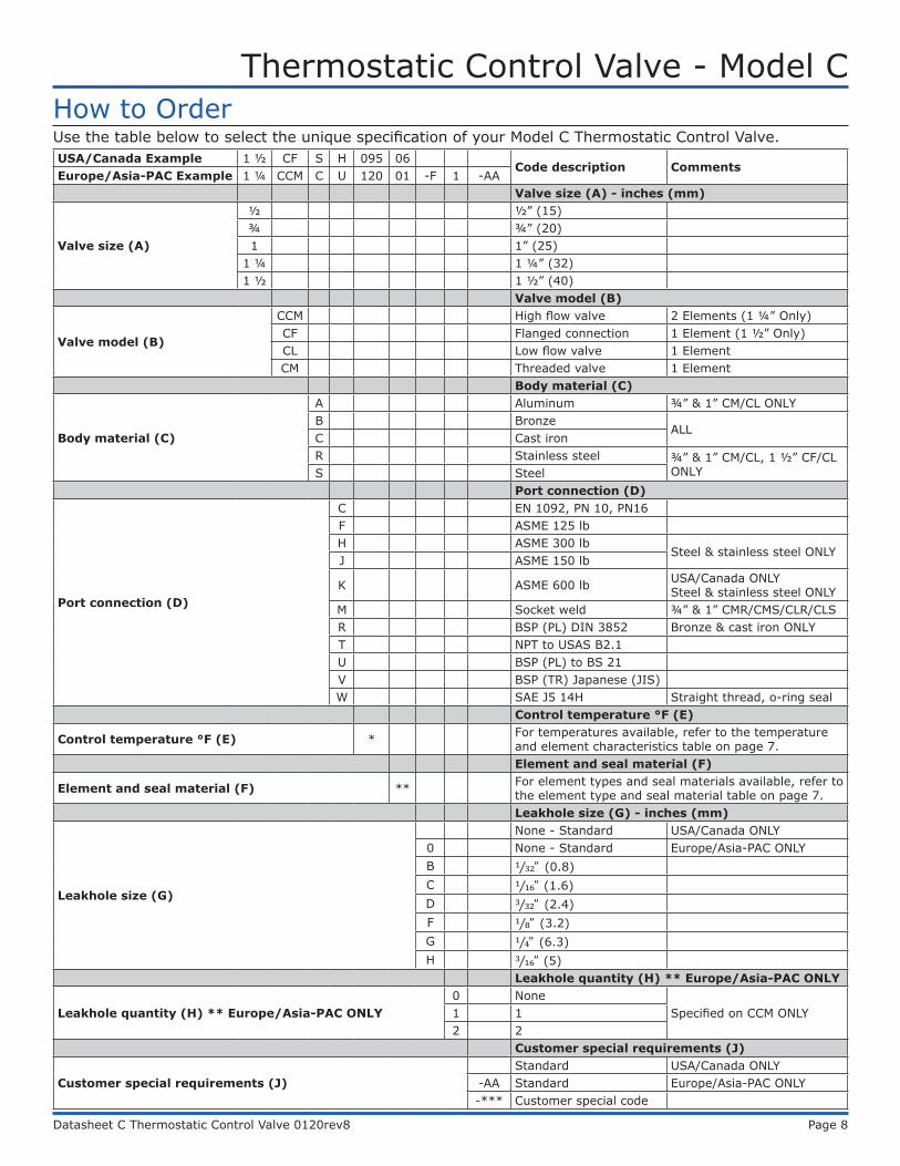
How to OrderUSA/Canada Example 1 ½ CF S H 095 06
Code description CommentsEurope/Asia-PAC Example 1 ¼ CCM C U 120 01 -F 1 -AA
Valve size (A) - inches (mm)
Valve size (A)
½ ½” (15)¾ ¾” (20)1 1” (25)
1 ¼ 1 ¼” (32)1 ½ 1 ½” (40)
Valve model (B)
Valve model (B)
CCM High flow valve 2 Elements (1 ¼” Only)CF Flanged connection 1 Element (1 ½” Only)CL Low flow valve 1 ElementCM Threaded valve 1 Element
Body material (C)
Body material (C)
A Aluminum ¾” & 1” CM/CL ONLYB Bronze
ALLC Cast ironR Stainless steel ¾” & 1” CM/CL, 1 ½” CF/CL
ONLYS SteelPort connection (D)
Port connection (D)
C EN 1092, PN 10, PN16F ASME 125 lbH ASME 300 lb
Steel & stainless steel ONLYJ ASME 150 lb
K ASME 600 lb USA/Canada ONLY Steel & stainless steel ONLY
M Socket weld ¾” & 1” CMR/CMS/CLR/CLSR BSP (PL) DIN 3852 Bronze & cast iron ONLYT NPT to USAS B2.1U BSP (PL) to BS 21V BSP (TR) Japanese (JIS)W SAE J5 14H Straight thread, o-ring seal
Control temperature °F (E)
Control temperature °F (E) * For temperatures available, refer to the temperature and element characteristics table on page 7.Element and seal material (F)
Element and seal material (F) ** For element types and seal materials available, refer to the element type and seal material table on page 7.Leakhole size (G) - inches (mm)
Leakhole size (G)
None - Standard USA/Canada ONLY0 None - Standard Europe/Asia-PAC ONLYB 1⁄32” (0.8)C 1⁄16” (1.6)D 3⁄32” (2.4)F 1⁄8” (3.2)G 1⁄4” (6.3)H 3⁄16” (5)
Leakhole quantity (H) ** Europe/Asia-PAC ONLY
Leakhole quantity (H) ** Europe/Asia-PAC ONLY0 None
Specified on CCM ONLY1 12 2
Customer special requirements (J)
Customer special requirements (J)Standard USA/Canada ONLY
-AA Standard Europe/Asia-PAC ONLY-*** Customer special code
Use the table below to select the unique specification of your Model C Thermostatic Control Valve.
Thermostatic Control Valve - Model C
Datasheet C Thermostatic Control Valve 0120rev8 Page 9
Specification
Weights
MaterialValve size and model
½ CL/CM ¾ CL/CM 1 CL/CM
1 ¼ CM 1 ½ CL/CM 1 ¼ CCM 1 ½ CFCF 1 ½ CFRJ
1 ½ CFSJ1 ½ CFRH 1 ½ CFSH
1 ½ CFRK 1 ½ CFSK
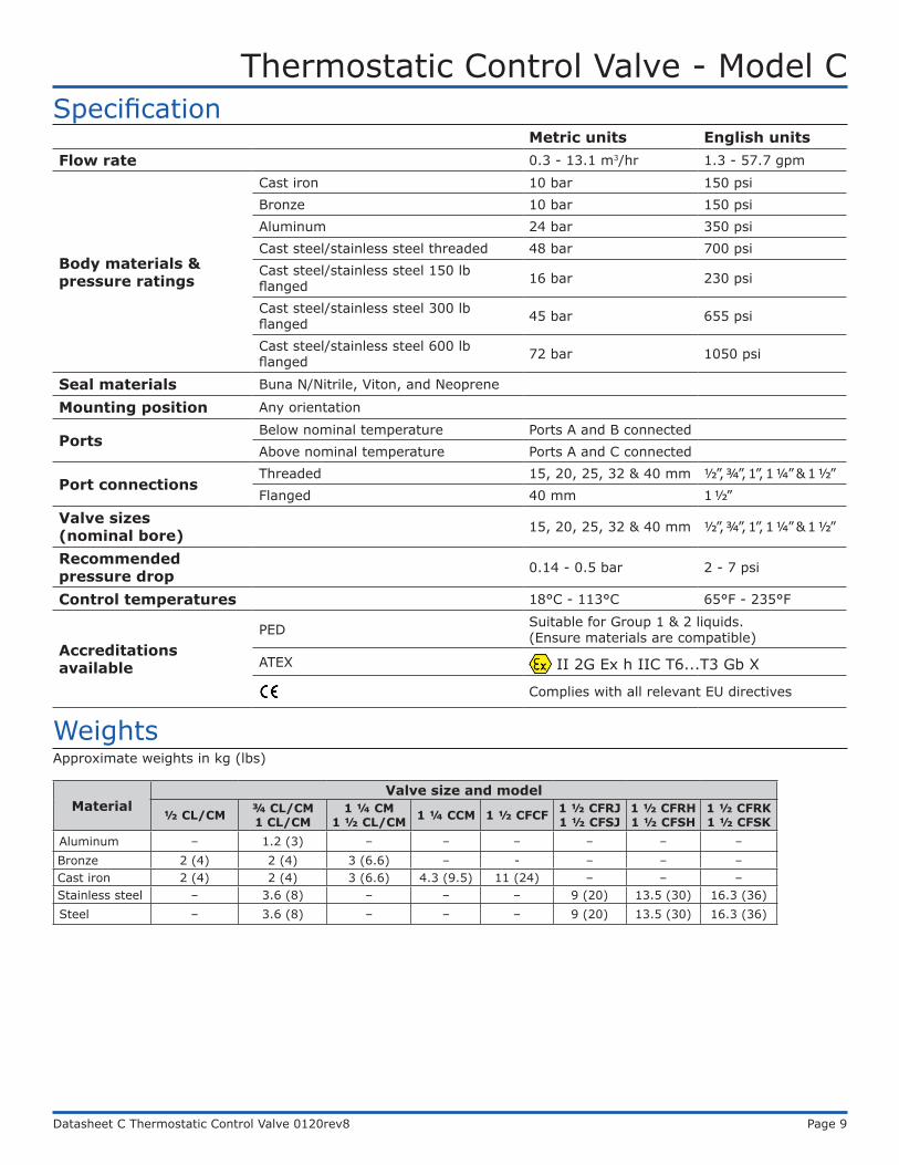
Aluminum – 1.2 (3) – – – – – –Bronze 2 (4) 2 (4) 3 (6.6) – - – – –Cast iron 2 (4) 2 (4) 3 (6.6) 4.3 (9.5) 11 (24) – – –Stainless steel – 3.6 (8) – – – 9 (20) 13.5 (30) 16.3 (36)Steel – 3.6 (8) – – – 9 (20) 13.5 (30) 16.3 (36)
Approximate weights in kg (lbs)
Metric units English unitsFlow rate 0.3 - 13.1 m3/hr 1.3 - 57.7 gpm
Body materials & pressure ratings
Cast iron 10 bar 150 psiBronze 10 bar 150 psiAluminum 24 bar 350 psiCast steel/stainless steel threaded 48 bar 700 psiCast steel/stainless steel 150 lb flanged 16 bar 230 psi
Cast steel/stainless steel 300 lb flanged 45 bar 655 psi
Cast steel/stainless steel 600 lb flanged 72 bar 1050 psi
Seal materials Buna N/Nitrile, Viton, and Neoprene
Mounting position Any orientation
PortsBelow nominal temperature Ports A and B connectedAbove nominal temperature Ports A and C connected
Port connectionsThreaded 15, 20, 25, 32 & 40 mm ½”, ¾”, 1”, 1 ¼” & 1 ½”Flanged 40 mm 1 ½”
Valve sizes (nominal bore) 15, 20, 25, 32 & 40 mm ½”, ¾”, 1”, 1 ¼” & 1 ½”
Recommended pressure drop 0.14 - 0.5 bar 2 - 7 psi
Control temperatures 18°C - 113°C 65°F - 235°F
Accreditations available
PED Suitable for Group 1 & 2 liquids. (Ensure materials are compatible)
ATEX II 2G Ex h IIC T6...T3 Gb X
Complies with all relevant EU directives
Thermostatic Control Valve - Model C
Datasheet C Thermostatic Control Valve 0120rev8 Page 10
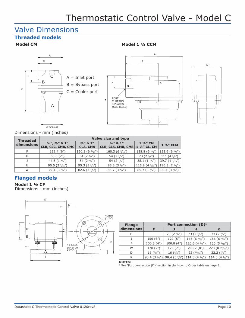
Valve Dimensions
D
W
40mm(11/2”)
A
J
4 HOLESDIA D onK PCD
H
F
B C
H
A
B
C
U
W SQUARE
J
F
Model CM
Model 1 ½ CF
A
C A = Inlet port
B = Bypass port
C = Cooler port
A
BC
B
Model 1 ¼ CCMThreaded models
Flanged models
PORT THREADS 3 PLACES (SEE TABLE)
Flange dimensions
Port connection (D)1
F J H KH - 73 (2 7⁄8”) 73 (2 7⁄8”) 73 (2 7⁄8”)J 150 (6”) 127 (5”) 156 (6 7⁄50”) 156 (6 7⁄50”)F 100.8 (4”) 100.8 (4”) 120.6 (4 3⁄4”) 130 (5 6⁄50”)W 178 (7”) 178 (7”) 203.2 (8”) 223 (8 39⁄50”)D 16 (5⁄8”) 16 (5⁄8”) 22 (31⁄36”) 22.2 (7⁄8”)K 98.4 (3 7⁄8”) 98.4 (3 7⁄8”) 114.3 (4 1⁄2”) 114.3 (4 1⁄2”)
Dimensions - mm (inches)
Dimensions - mm (inches)
Threaded dimensions
Valve size and type½”, ¾” & 1”
CLB, CLC, CMB, CMC¾” & 1” CLA, CMA
¾” & 1” CLR, CLS, CMR, CMS
1 ¼” CM 1 ½” CL, CM 1 ¼” CCM
F 152.4 (6”) 160.3 (6 5⁄16”) 160.3 (6 5⁄16”) 158.8 (6 1⁄4”) 155.6 (6 1⁄8”) H 50.8 (2”) 54 (2 1⁄8”) 54 (2 1⁄8”) 73 (2 7⁄8”) 111 (4 3⁄8”)J 44.5 (1 3⁄4”) 54 (2 1⁄8”) 54 (2 1⁄8”) 38.1 (1 1⁄2”) 39.7 (1 5⁄16”)U 90.5 (3 9⁄16”) 95.3 (3 3⁄4”) 95.3 (3 3⁄4”) 115.9 (4 9⁄16”) 190.5 (7 1⁄2”) W 79.4 (3 1⁄8”) 82.6 (3 1⁄4”) 85.7 (3 3⁄8”) 85.7 (3 3⁄8”) 98.4 (3 7⁄8”)
NOTES: 1 See ‘Port connection (D)’ section in the How to Order table on page 8.
Thermostatic Control Valve - Model C
Datasheet C Thermostatic Control Valve 0120rev8 Page 11
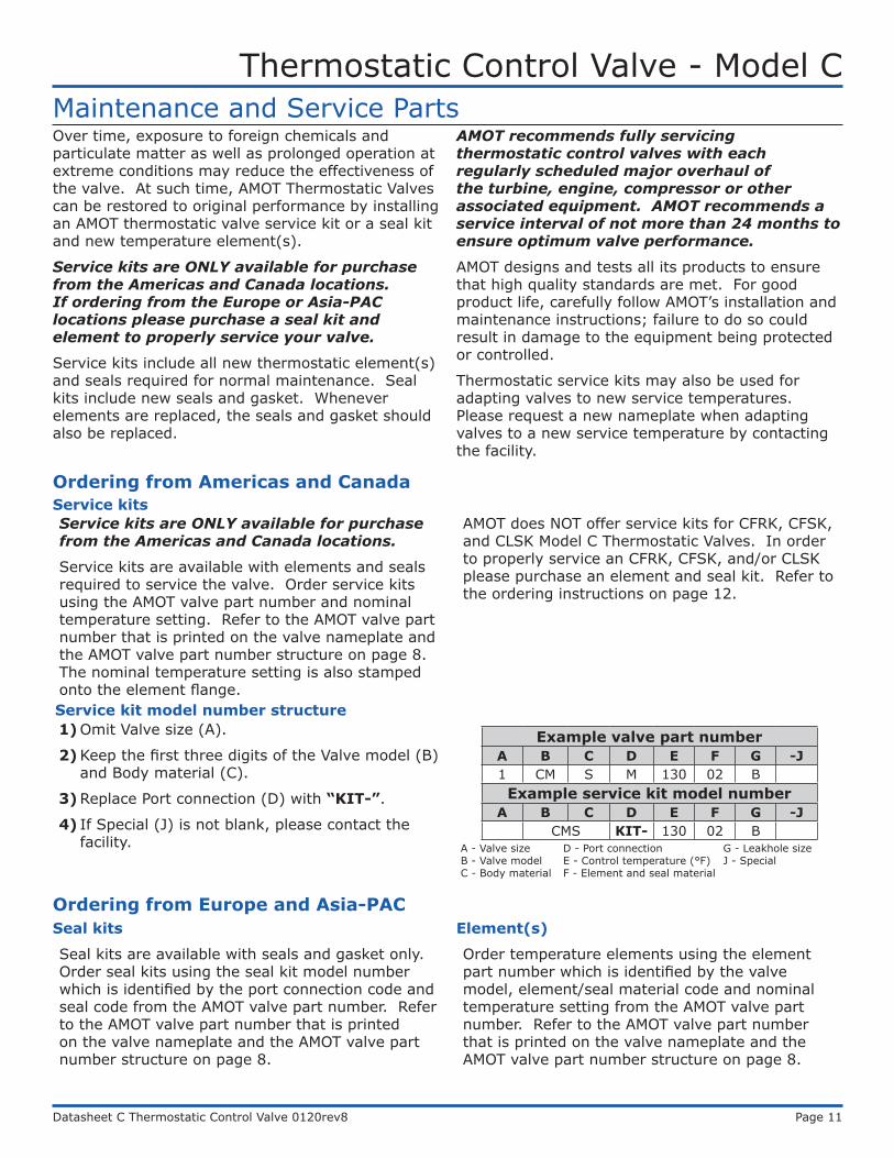
Maintenance and Service PartsOver time, exposure to foreign chemicals and particulate matter as well as prolonged operation at extreme conditions may reduce the effectiveness of the valve. At such time, AMOT Thermostatic Valves can be restored to original performance by installing an AMOT thermostatic valve service kit or a seal kit and new temperature element(s).
Service kits are ONLY available for purchase from the Americas and Canada locations. If ordering from the Europe or Asia-PAC locations please purchase a seal kit and element to properly service your valve.
Service kits include all new thermostatic element(s) and seals required for normal maintenance. Seal kits include new seals and gasket. Whenever elements are replaced, the seals and gasket should also be replaced.
AMOT recommends fully servicing thermostatic control valves with each regularly scheduled major overhaul of the turbine, engine, compressor or other associated equipment. AMOT recommends a service interval of not more than 24 months to ensure optimum valve performance.
AMOT designs and tests all its products to ensure that high quality standards are met. For good product life, carefully follow AMOT’s installation and maintenance instructions; failure to do so could result in damage to the equipment being protected or controlled.
Thermostatic service kits may also be used for adapting valves to new service temperatures. Please request a new nameplate when adapting valves to a new service temperature by contacting the facility.
Ordering from Americas and Canada
Service kits are ONLY available for purchase from the Americas and Canada locations.
Service kits are available with elements and seals required to service the valve. Order service kits using the AMOT valve part number and nominal temperature setting. Refer to the AMOT valve part number that is printed on the valve nameplate and the AMOT valve part number structure on page 8. The nominal temperature setting is also stamped onto the element flange.
AMOT does NOT offer service kits for CFRK, CFSK, and CLSK Model C Thermostatic Valves. In order to properly service an CFRK, CFSK, and/or CLSK please purchase an element and seal kit. Refer to the ordering instructions on page 12.
Service kit model number structure
Example valve part numberA B C D E F G -J1 CM S M 130 02 BExample service kit model number
A B C D E F G -JCMS KIT- 130 02 B
1) Omit Valve size (A).
2) Keep the first three digits of the Valve model (B) and Body material (C).
3) Replace Port connection (D) with “KIT-”.
4) If Special (J) is not blank, please contact the facility. A - Valve size D - Port connection G - Leakhole size
B - Valve model E - Control temperature (°F) J - SpecialC - Body material F - Element and seal material
Ordering from Europe and Asia-PACSeal kits
Seal kits are available with seals and gasket only. Order seal kits using the seal kit model number which is identified by the port connection code and seal code from the AMOT valve part number. Refer to the AMOT valve part number that is printed on the valve nameplate and the AMOT valve part number structure on page 8.
Element(s)
Order temperature elements using the element part number which is identified by the valve model, element/seal material code and nominal temperature setting from the AMOT valve part number. Refer to the AMOT valve part number that is printed on the valve nameplate and the AMOT valve part number structure on page 8.
Service kits
Thermostatic Control Valve - Model C
Datasheet C Thermostatic Control Valve 0120rev8 Page 12
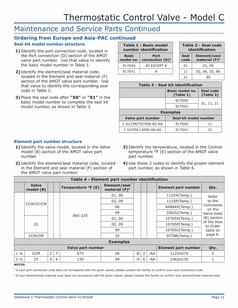
Ordering from Europe and Asia-PAC continuedSeal kit model number structure
1) Identify the port connection code, located in the Port connection (D) section of the AMOT valve part number. Use that value to identify the basic model number in Table 1.
2) Identify the element/seal material code, located in the Element and seal material (F) section of the AMOT valve part number. Use that value to identify the corresponding seal code in Table 2.
3) Place the seal code after “X0” or “X1” in the basic model number to complete the seal kit model number, as shown in Table 3.
Maintenance and Service Parts Continued
Table 3 - Seal kit identificationBasic model no.
(Table 1)Seal code (Table 2)
9170X001, 11, 21
9170X1
ExamplesValve part number Seal kit model number
1 ¼CCMCT07506-B2-AA 9170X0 11
1 ½CFSK13099-00-AA 9170X1 21
Table 1 - Basic model number identificationBasic
model no.Port
connection (D)2
9170X0 All EXCEPT K
9170X1 K
Table 2 - Seal code identification
Seal code
Element/seal material (F)3
01 01, 09
11 02, 06, 35, 86
21 99
Element part number structure1) Identify the valve model, located in the Valve
model (B) section of the AMOT valve part number.
2) Identify the element/seal material code, located in the Element and seal material (F) section of the AMOT valve part number.
3) Identify the temperature, located in the Control temperature °F (E) section of the AMOT valve part number.
4) Use those 3 codes to identify the proper element part number, as shown in Table 4.
Table 4 - Element part number identificationValve
model (B) Temperature °F (E) Element/seal material (F)3 Element part number Qty.
CCM/CF/CM
065-235
01, 06 1125X(Temp.) Refer to the
Comments on the
Valve body (B) section of the How to Order table on page 8.
02, 09 1125P(Temp.)86 44844X(Temp.)99 3362U(Temp.)
CL01, 06 10765X(Temp.)02, 09 10765P(Temp.)
99 10765U(Temp.)CCM/CM 35 9778R(Temp.)
ExamplesValve part number Element part number Qty.
1 ¼ CCM C T 075 06 -B 2 -AA 1125X075 21 ½ CF S K 130 99 -0 0 -AA 3362U130 1
NOTES:2 If your port connection code does not correspond with the given values, please contact the facility to confirm your port connection code.3 If your element/seal material code does not correspond with the given values, please contact the facility to confirm your element/seal material code.
Thermostatic Control Valve - Model C
Datasheet C Thermostatic Control Valve 0120rev8 Page 13
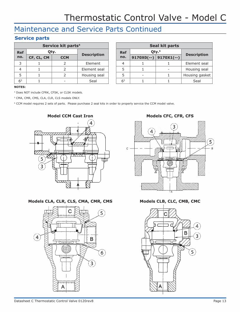
Maintenance and Service Parts ContinuedService parts
NOTES:4 Does NOT include CFRK, CFSK, or CLSK models.5 CMA, CMR, CMS, CLA, CLR, CLS models ONLY.6 CCM model requires 2 sets of parts. Please purchase 2 seal kits in order to properly service the CCM model valve.
Service kit parts4
Ref no.
Qty.Description
CF, CL, CM CCM3 1 2 Element4 1 2 Element seal5 1 2 Housing seal65 1 - Seal
Seal kit partsRef no.
Qty.6
Description9170X0(--) 9170X1(--)
4 1 1 Element seal5 1 - Housing seal5 - 1 Housing gasket65 1 1 Seal
Models CLA, CLR, CLS, CMA, CMR, CMS Models CLB, CLC, CMB, CMC
Models CFC, CFR, CFSModel CCM Cast Iron
Thermostatic Control Valve - Model C
Datasheet C Thermostatic Control Valve 0120rev8 Page 14
Contact
Americas Europe, Middle East and Africa
AMOT USA8824 Fallbrook Dr.Houston, TX 77064USA
Tel: +1 (281) 940 1800Fax: +1 (713) 559 9419Email: [email protected]
AMOT UKWestern WayBury St. EdmundsSuffolk, IP33 3SZEngland
Tel: +44 1284 715739Fax: +44 1284 760256Email: [email protected]
AMOT GermanyRondenbarg 2522525 HamburgGermany
Tel: +49 40 8537 1298Fax: +49 40 8537 1331Email: [email protected] Pacific
AMOT ShanghaiBd. 7A, No. 568, Longpan Rd., Malu JiadingShanghai 201801China
Tel: +86 21 5910 4052Fax: +86 21 5237 8560Email: [email protected]
www.amot.com