the solar-b euv imaging spectrometer: an overview of eis j. l. culhane mullard space science...
Post on 21-Dec-2015
216 views
TRANSCRIPT
The Solar-B EUV Imaging Spectrometer:
an Overview of EIS
J. L. Culhane
Mullard Space Science LaboratoryUniversity College London
AIA HMI Team Meeting , Monterey 13-17 Feb., 2006
EIS Instrument Overview
2
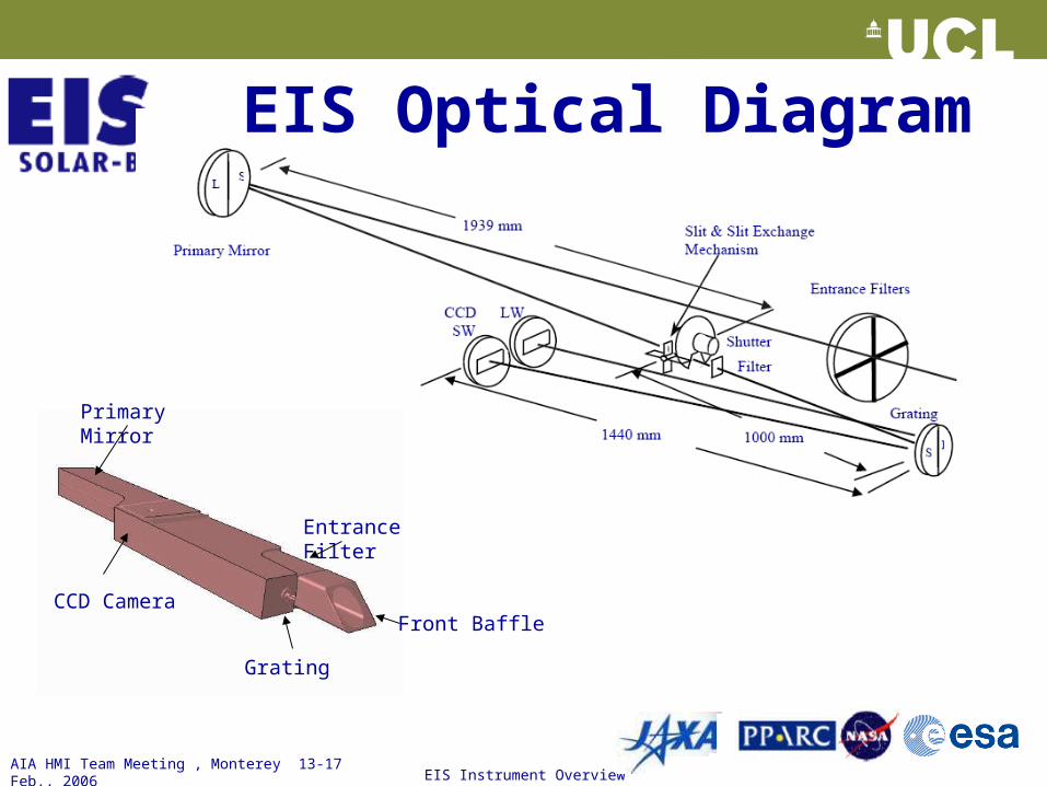
EIS Optical Diagram
Grating
Front Baffle
Entrance Filter
Primary Mirror
CCD Camera
AIA HMI Team Meeting , Monterey 13-17 Feb., 2006
EIS Instrument Overview
3
• Each element measured independently at Brookhaven• Complete instrument calibrated end-to-end at RAL• Instrument contamination budget maintained by keeping at
positive dry Nitrogen pressure• Continuous QCM monitoring pre and post launch• Temperature insensitive lines in QS measured throughout
mission• Two GSFC EUNIS rocket flights during mission• Philosophy based on SOHO CDS approach.
EIS Calibration
AIA HMI Team Meeting , Monterey 13-17 Feb., 2006
EIS Instrument Overview
4
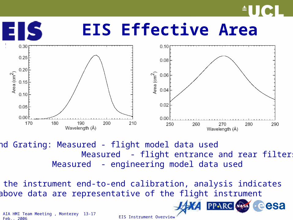
EIS Effective Area
Primary and Grating: Measured - flight model data usedFilters: Measured - flight entrance and rear filters CCD QE: Measured - engineering model data used
Following the instrument end-to-end calibration, analysis indicates that the above data are representative of the flight instrument
AIA HMI Team Meeting , Monterey 13-17 Feb., 2006
EIS Instrument Overview
5
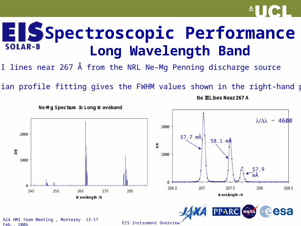
Spectroscopic PerformanceLong Wavelength Band
• Ne III lines near 267 Å from the NRL Ne–Mg Penning discharge source
• Gaussian profile fitting gives the FWHM values shown in the right-hand panel
57.7 mÅ58.1 mÅ
57.9 mÅ
~ 4600
AIA HMI Team Meeting , Monterey 13-17 Feb., 2006
EIS Instrument Overview
6
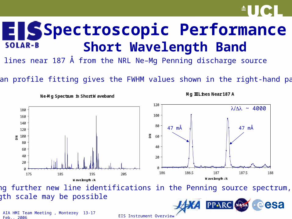
Spectroscopic PerformanceShort Wavelength Band
• Mg III lines near 187 Å from the NRL Ne–Mg Penning discharge source
• Gaussian profile fitting gives the FWHM values shown in the right-hand panel
47 mÅ 47 mÅ
~ 4000
• Following further new line identifications in the Penning source spectrum, an absolute wavelength scale may be possible
AIA HMI Team Meeting , Monterey 13-17 Feb., 2006
EIS Instrument Overview
7
END OF TALK
AIA HMI Team Meeting , Monterey 13-17 Feb., 2006
EIS Instrument Overview
8
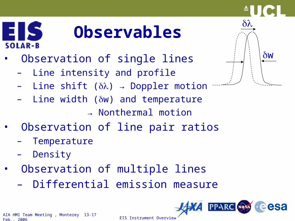
Observables
• Observation of single lines– Line intensity and profile– Line shift () → Doppler motion– Line width (w) and temperature
→ Nonthermal motion
• Observation of line pair ratios– Temperature– Density
• Observation of multiple lines– Differential emission measure
w
AIA HMI Team Meeting , Monterey 13-17 Feb., 2006
EIS Instrument Overview
9
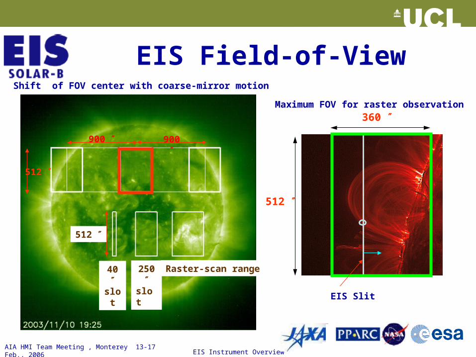
EIS Field-of-View
360
512
EIS Slit
Maximum FOV for raster observation
512
900 900
Raster-scan range
Shift of FOV center with coarse-mirror motion
250 slot
40 slot
512
AIA HMI Team Meeting , Monterey 13-17 Feb., 2006
EIS Instrument Overview
10
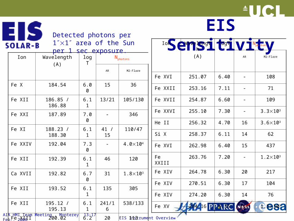
EIS Sensitivity
Ion Wavelength
(A)
logT Nphotons
AR M2-Flare
Fe X 184.54 6.00 15 36
Fe XII 186.85 / 186.88 6.11 13/21 105/130
Fe XXI 187.89 7.00 - 346
Fe XI 188.23 / 188.30 6.11 41 / 15 110/47
Fe XXIV 192.04 7.30 - 4.0104
Fe XII 192.39 6.11 46 120
Ca XVII 192.82 6.70 31 1.8103
Fe XII 193.52 6.11 135 305
Fe XII 195.12 / 195.13 6.11 241/16 538/133
Fe XIII 200.02 6.20 20 113
Fe XIII 202.04 6.20 35 82
Fe XIII 203.80 / 203.83 6.20 7/20 38/114
Detected photons per 11 area of the Sun per 1 sec exposure. Ion Wavelength
(A)
logT Nphotons
AR M2-Flare
Fe XVI 251.07 6.40 - 108
Fe XXII 253.16 7.11 - 71
Fe XVII 254.87 6.60 - 109
Fe XXVI 255.10 7.30 - 3.3103
He II 256.32 4.70 16 3.6103
Si X 258.37 6.11 14 62
Fe XVI 262.98 6.40 15 437
Fe XXIII 263.76 7.20 - 1.2103
Fe XIV 264.78 6.30 20 217
Fe XIV 270.51 6.30 17 104
Fe XIV 274.20 6.30 14 76
Fe XV 284.16 6.35 111 1.5103
AIA HMI Team Meeting , Monterey 13-17 Feb., 2006
EIS Instrument Overview
11
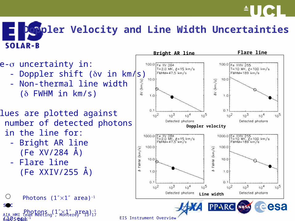
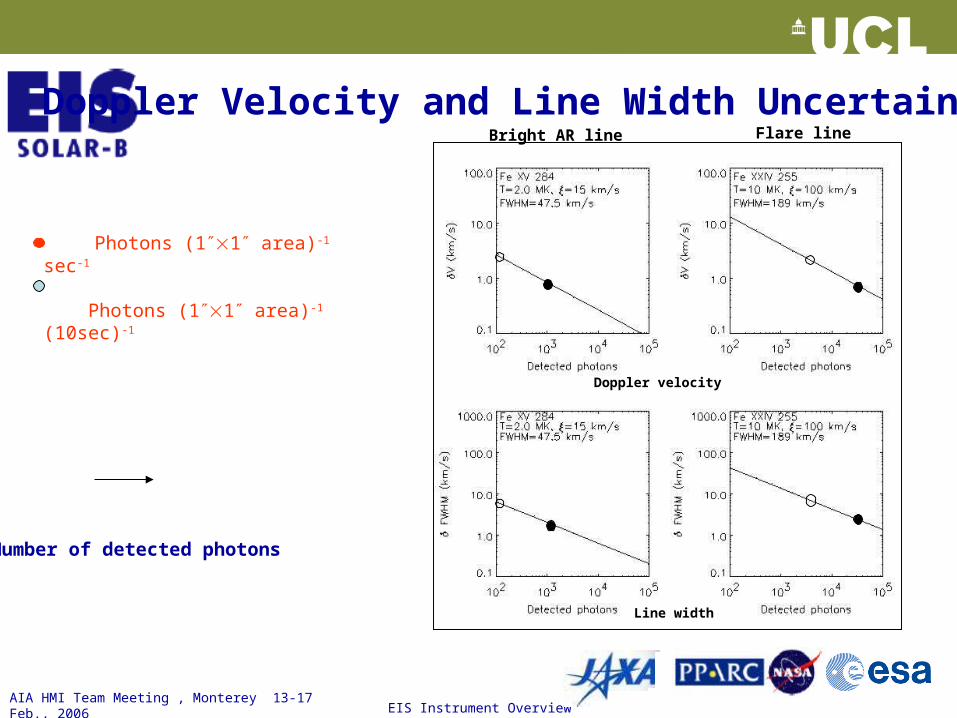
Doppler Velocity and Line Width Uncertainties
Doppler velocity
Line width
Bright AR line Flare line
Photons (11 area)-1 sec Photons (11 area)-1 (10sec)-1
One- uncertainty in: - Doppler shift (v in km/s) - Non-thermal line width ( FWHM in km/s)
Values are plotted against number of detected photons in the line for: - Bright AR line (Fe XV/284 Å) - Flare line (Fe XXIV/255 Å)
AIA HMI Team Meeting , Monterey 13-17 Feb., 2006
EIS Instrument Overview
12
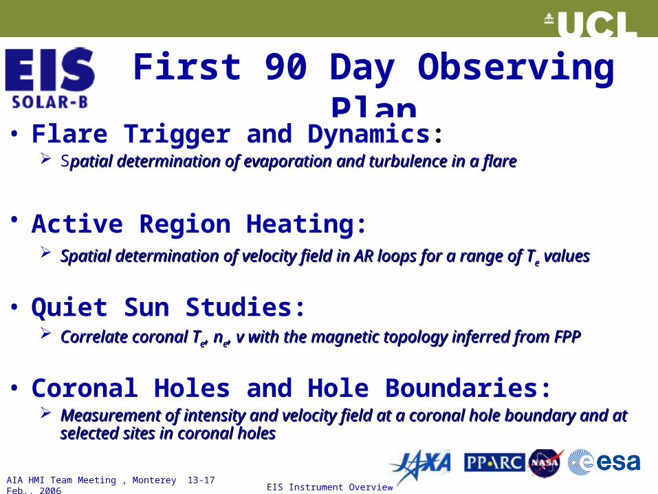
First 90 Day Observing Plan
• Flare Trigger and Dynamics: Spatial determination of evaporation and turbulence in a flarepatial determination of evaporation and turbulence in a flare
• Active Region Heating: Spatial determination of velocity field in AR loops for a range of TSpatial determination of velocity field in AR loops for a range of Tee values values
• Quiet Sun Studies: Correlate coronal TCorrelate coronal Tee, n, nee, v with the magnetic topology inferred from FPP, v with the magnetic topology inferred from FPP
• Coronal Holes and Hole Boundaries: Measurement of intensity and velocity field at a coronal hole boundary and at Measurement of intensity and velocity field at a coronal hole boundary and at
selected sites in coronal holesselected sites in coronal holes
AIA HMI Team Meeting , Monterey 13-17 Feb., 2006
EIS Instrument Overview
13
SUMMARY
• Following SOHO CDS, the EIS instrument will provide the next steps in EUV spectral imaging of the corona: – x 10 enhancement in Aeff from use of multilayers and CCDs– x 5 enhancement in spectral resolution– x 3 enhancement in spatial resolution– Like CDS; absolute calibration performed to ± 20%
• EIS will:– Address a broad range of coronal science topics – Enable major goals of Solar-B mission by relating coronal
response to magnetic flux emergence and material flows
AIA HMI Team Meeting , Monterey 13-17 Feb., 2006
EIS Instrument Overview
14
• Large Effective Area in two EUV bands: 170-210 Å and 250-290 Å– Multi-layer Mirror (15 cm dia ) and Grating; both with optimized Mo/Si Coatings– CCD camera; Two 2048 x 1024 high QE back illuminated CCDs
• Spatial resolution: 1 arc sec pixels/2 arc sec resolution
• Line spectroscopy with ~ 25 km/s per pixel sampling
• Field of View : – Raster: 6 arc min×8.5 arc min; – FOV centre moveable E – W by ± 15 arc min
• Wide temperature coverage: log T = 4.7, 5.4, 6.0 - 7.3 K
• Simultaneous observation of up to 25 lines/spectral windows
EIS - Instrument Features
AIA HMI Team Meeting , Monterey 13-17 Feb., 2006
EIS Instrument Overview
15
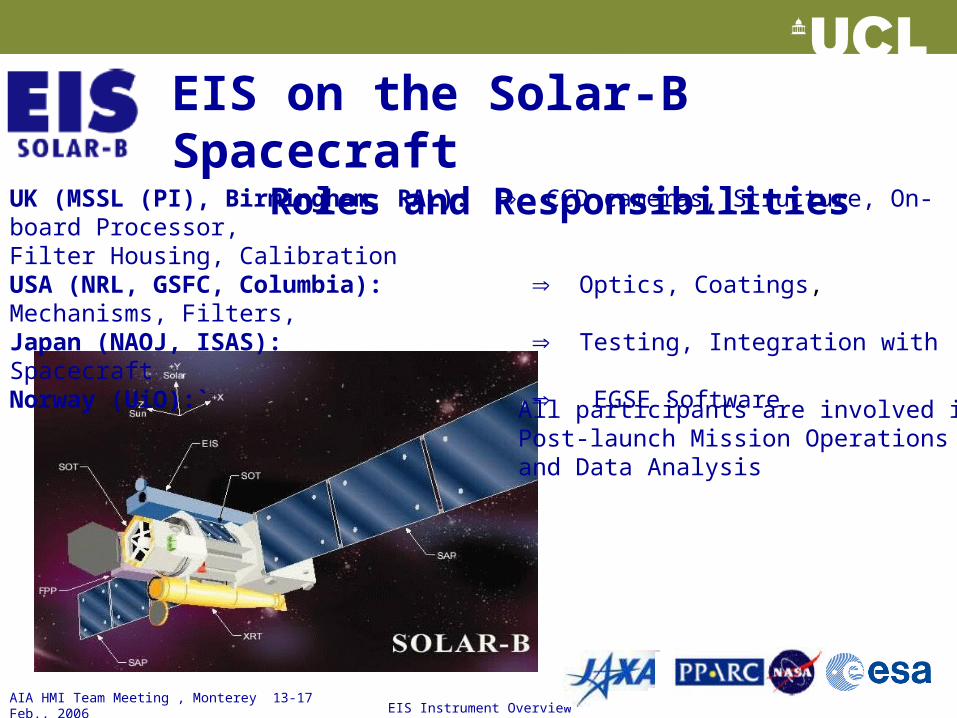
EIS on the Solar-B SpacecraftRoles and Responsibilities
UK (MSSL (PI), Birmingham, RAL): CCD cameras, Structure, On-board Processor, Filter Housing, Calibration
USA (NRL, GSFC, Columbia): Optics, Coatings, Mechanisms, Filters,Japan (NAOJ, ISAS): Testing, Integration with SpacecraftNorway (UiO):` EGSE Software
All participants are involved inPost-launch Mission Operationsand Data Analysis
AIA HMI Team Meeting , Monterey 13-17 Feb., 2006
EIS Instrument Overview
16
Processed Science Data Products
• Intensity Maps (TIntensity Maps (Tee, n, nee):):
– images of region being rastered from the zeroth moments of
strongest spectral lines
• Doppler Shift Maps (Bulk Velocity):Doppler Shift Maps (Bulk Velocity): – images of region being rastered from first moments of the
strongest spectral lines
• Line Width Maps (Non-thermal Velocity):Line Width Maps (Non-thermal Velocity): – images of region being rastered from second moments of the
strongest spectral lines
AIA HMI Team Meeting , Monterey 13-17 Feb., 2006
EIS Instrument Overview
17
Doppler velocity
Line width
Bright AR line Flare line
Photons (11 area)-1 sec-1
Photons (11 area)-1 (10sec)-1
Number of detected photons
Doppler Velocity and Line Width Uncertainties
AIA HMI Team Meeting , Monterey 13-17 Feb., 2006
EIS Instrument Overview
18
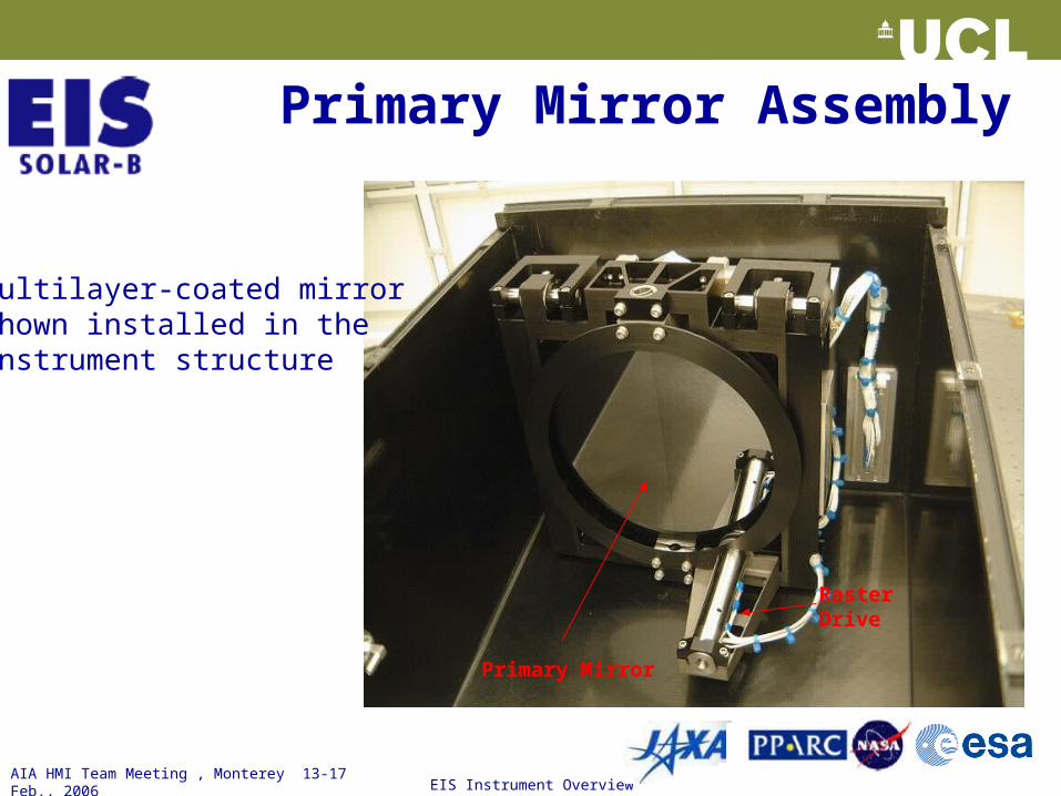
Primary Mirror
Raster Drive
Primary Mirror Assembly
• Multilayer-coated mirror shown installed in the instrument structure
AIA HMI Team Meeting , Monterey 13-17 Feb., 2006
EIS Instrument Overview
19
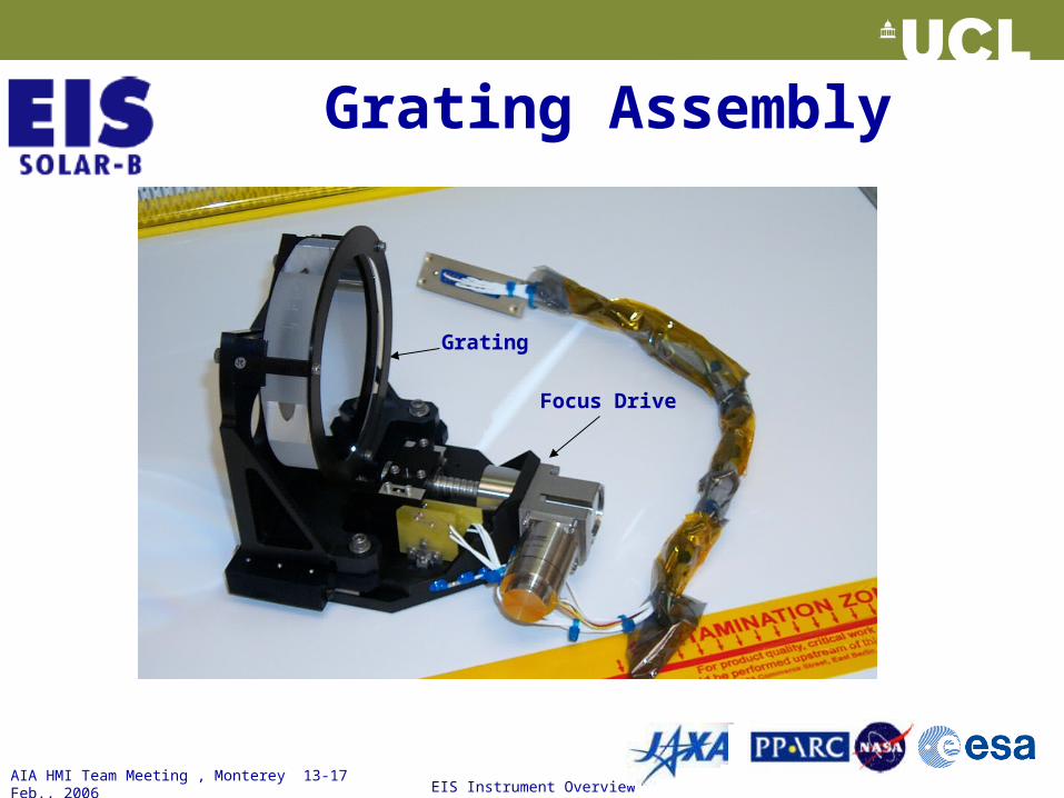
Grating Assembly
Grating
Focus Drive
AIA HMI Team Meeting , Monterey 13-17 Feb., 2006
EIS Instrument Overview
20
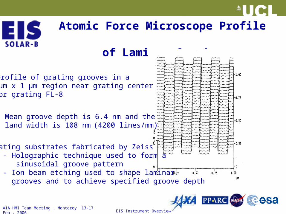
Atomic Force Microscope Profile of Laminar Grating
.
• Mean groove depth is 6.4 nm and the land width is 108 nm (4200 lines/mm)
• AFM profile of grating grooves in a 1 μm x 1 μm region near grating center for grating FL-8
• Grating substrates fabricated by Zeiss - Holographic technique used to form a sinusoidal groove pattern - Ion beam etching used to shape laminar grooves and to achieve specified groove depth
AIA HMI Team Meeting , Monterey 13-17 Feb., 2006
EIS Instrument Overview
21
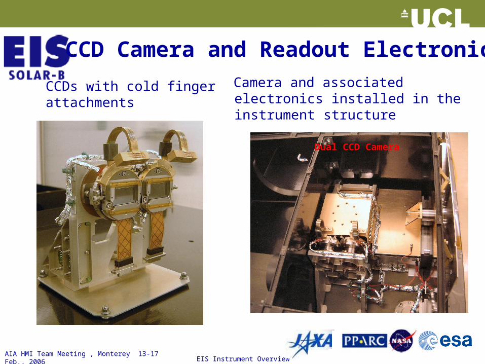
Dual CCD Camera
CCD Camera and Readout Electronics
Camera and associated electronics installed in the instrument structure
CCDs with cold finger attachments
AIA HMI Team Meeting , Monterey 13-17 Feb., 2006
EIS Instrument Overview
22
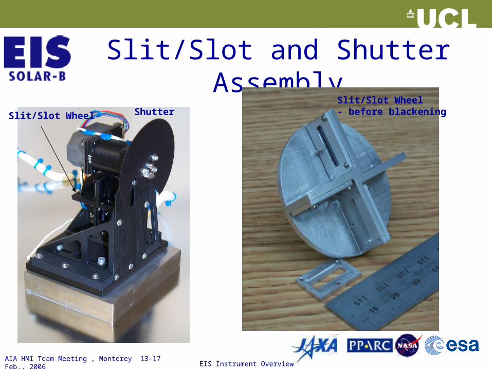
Slit/Slot and Shutter Assembly
Slit/Slot Wheel ShutterSlit/Slot Wheel- before blackening
AIA HMI Team Meeting , Monterey 13-17 Feb., 2006
EIS Instrument Overview
23
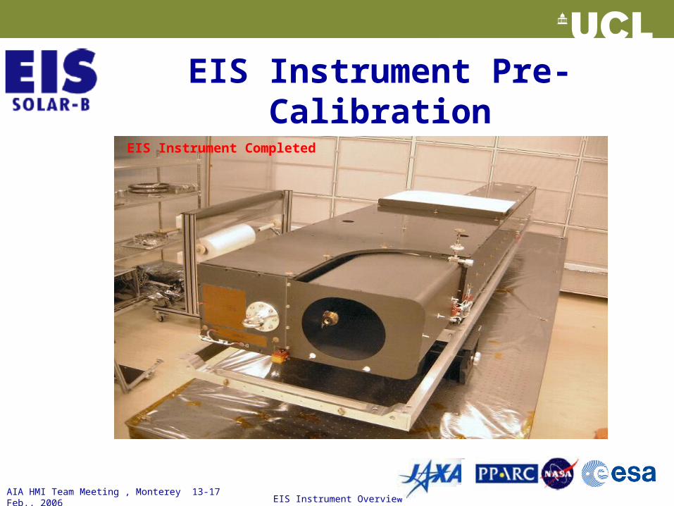
EIS Instrument Pre-Calibration
EIS Instrument Completed