the mars surveyor '01 rover and robotic arm
TRANSCRIPT

The Mars Surveyor '01 Rover and Robotic Arm†
Robert G. Bonitz, Tam T. Nguyen, Won S. KimJet Propulsion Laboratory
California Institute of Technology4800 Oak Grove Drive
Pasadena, CA 91109-8099818-354-4628
† 0-7803-5846-5/00/$10.00 © 2000 IEEE
Abstract - The Mars Surveyor 2001 Lander will carry withit both a Robotic Arm and Rover to support various scienceand technology experiments. The Marie Curie Rover, thetwin sister to Sojourner Truth, is expected to explore thesurface of Mars in early 2002. Scientific investigations todetermine the elemental composition of surface rocks andsoil using the Alpha Proton X-Ray Spectrometer (APXS)will be conducted along with several technologyexperiments including the Mars Experiment onElectrostatic Charging (MEEC) and the Wheel AbrasionExperiment (WAE). The Rover will follow uplinkedoperational sequences each day, but will be capable ofautonomous reactions to the unpredictable features of theMartian environment.
The Mars Surveyor 2001 Robotic Arm will perform roverdeployment, and support various positioning, digging, andsample acquiring functions for MECA (MarsEnvironmental Compatibility Assessment) and MossbauerSpectrometer experiments. The Robotic Arm will alsocollect its own sensor data for engineering data analysis.The Robotic Arm Camera (RAC) mounted on the forearmof the Robotic Arm will capture various images with a widerange of focal length adjustment during scientificexperiments and rover deployment
1. INTRODUCTION
The Mars 2001 Surveyor Lander is the next mission in theMars Surveyor Program whose primary objective is tofurther our understanding of the biological potential andpossible biological history of Mars, and to search forindicators of past and/or present life. The Lander (Figure 1)is scheduled to land on the equatorial region (3N to 12S) ofMars on Jan. 27, 2002. It is a platform for scienceinstruments and technology experiments designed toprovide key insights to decision regarding successful andcost-effective human missions to Mars. Two keyinstruments are the Robotic Arm and the Marie CurieRover.
The primary purpose of the Robotic Arm is to support theother science instruments by digging trenches in theMartian soil, acquiring soil samples, positioning arm-
mounted science instruments near or on appropriate targets,and deploying the Marie Curie Rover to the surface. It willalso be used to conduct soil mechanics experiments toinvestigate the physical properties of the surface andsubsurface materials in the workspace. Details of theRobotic Arm system and operations are described in section2.
Figure 1 Mars Surveyor 2001 Lander
After the Robotic Arm deploys the Marie Curie rover, thesister of the Mars Pathfinder Sojourner rover, onto theMartian surface, the rover will begin traversing the surfacein the vicinity of the Lander. The rover visiting locationswill be designated by a human operator using engineeringdata collected during previous traversals and end-of-sol(Martian day) stereo images captured by the Lander stereocameras [6]. During the traversals the rover willautonomously avoid rock, drop-off, and slope hazards. Itwill change its course to avoid these hazards and will t urnback toward its goals whenever the hazards are no longer inits way. The rover uses "dead reckoning" counting wheelturns and on-board rate sensors to estimate position.Although the rover telemetry will record its responses tohuman driver commands in detail, the vehicle's actualpositions will not be known until examination of theLander stereo images at the end of the sol. The rover will

stop at several sites of interest for various scientific andengineering experiments.
2. ROBOTIC ARM
The Mars Surveyor 2001 Robotic Arm (Figure 2) is a low-mass 4-degree-of-freedom manipulator with a back-hoedesign [9] inherited from the Mars Surveyor '98 RoboticArm. The end effector (Figure 2) consists of a scoop fordigging and soil sample acquisition, secondary blades forscraping, an electrometer for measuring triboelectric chargeand atmospheric ionization, and a crowfoot for deployingthe Rover from the Lander to the surface. Control of theArm is achieved by a combination of software executing onthe Lander computer and firmware resident in the RoboticArm electronics. The Robotic Arm is an essentialinstrument in achieving the scientific goals of the MarsSurveyor 2001 mission by providing support to the otherMars Surveyor 2001 science instruments as well asconducting Arm-specific soil mechanics experiments.
Figure 2 Robotic Arm with Rover Model
Robotic Arm as a support instrument
Support to the MECA - One of the primary mission goals isto analyze soil samples in the MECA Wet Chemistry Lab.The Robotic Arm will support this goal by acquiring bothsurface and subsurface soil samples in its scoop from thearea in the vicinity of the Lander and dumping the soilsamples into the MECA wet chemistry cells andmicroscope port. Subsurface soil samples will be acquiredat varying depths from within trenches excavated by theArm, potentially to a depth of 50cm depending on the soilconditions. The Arm is capable of reaching deeper than50cm below the surface, but operational constraints areexpected to limit practical digging depth. The Arm willdump soil samples on the MECA material patch plates forimaging by the Robotic Arm Camera to measure propertiessuch as soil particle wear, hardness, and adhesion. TheArm will also position the MECA electrometer formeasuring triboelectric charge during digging andatmospheric ionization.
Support to the Robotic Arm Camera - A key element of theMars Surveyor 2001 instrument suite is the Robotic ArmCamera (RAC) mounted on the forearm just behind thewrist. Soon after landing the Robotic Arm will position theRAC to take images of the Lander foot pads, providinguseful data in determining surface properties at thetouchdown site. Throughout the mission the Arm willperiodically position the RAC to take images of the surface,trench floor and end walls, and dumped soil piles. Duringsoil sample acquisition, the scoop will be positioned for theRAC to take close-up images of the soil samples in thescoop prior to delivery to the MECA. There is a divot in thescoop blade to contain small soil samples for very closeimaging by the RAC at a distance of 11mm. The Arm willalso position the RAC for imaging of the patch platelocated on the MECA, nearby rocks, and any other objectsof scientific interest within its workspace.
Support to the Mossbauer Spectrometer - The MossbauerSpectrometer is located on the Robotic Arm forearmbetween the elbow and RAC and is used to determine thecomposition and abundance of iron-bearing minerals. TheRobotic Arm will position the Mossbauer on its calibrationand magnetic targets located on the Lander deck as well ason soil targets within the reach and kinematic constraints ofthe Arm.
Support to the Marie Curie Rover - In the historical 1997Pathfinder Mission, a ramp pathway was used to drive theSojourner Truth Rover from the Lander deck to the Martiansurface. In the Mars Surveyor 2001 mission, the RoboticArm will be used instead to deploy the Marie Curie Roveron the Martian surface (Figure 3). In this new approach, a3-D terrain map generated by the Pancam Stereo Camerasystem will be used to determine the Rover deployment site.Two Rover deployment zones are defined. The primarydeployment zone is the area which is reachable by theRobot Arm and can be viewed by the Pancam. Thesecondary deployment zone is the area which is reachableby the Robot Arm but cannot be viewed by the Pancam. Ifthe Robotic Arm is forced to deploy the Rover in thesecondary zone, the non-stereo Robot Arm Camera (RAC)mounted on the Robot Arm forearm will be used.
In picking up the Rover, a crowfoot mechanism mountedon the Robot Arm wrist, together with a ball and wiremounted on the top surface of the Rover, will be used. Thisdesign allows +/-7 mm Robot Arm positioning error. Inorder to place the Rover on the Martian surface withoutbumping into the delicate Rover solar panel surface withthe crowfoot, careful studies are necessary since Robot Armpositioning, 3-D terrain map generation, and finding astable positioning point for a given non-trivial terrain allhave limited accuracy. In the visual approach, the Roverwill be moved down 3 cm (TBD) at a time, until thecrowfoot is disengaged from the ball. Other potentialapproaches that could reduce the total number of days forRover deployment are motor current sensing, short-motor-circuit, and open-motor-circuit approaches. These different

approaches will be carefully investigated includingthermal-vac tests, examining temperature dependencies.
Figure 3 Robotic Arm Deploying Rover
Robotic Arm as a Science Instrument
During the surface operations of the Mars Surveyor 2001payload, the Robotic Arm will also be used along with theother Mars Surveyor 2001 instruments to investigate thephysical properties of the surface and subsurface materialsin the workspace. The primary surface investigation by theRobotic Arm will be the direct measurements of themechanical properties using motor currents to estimateArm forces. Additional information will be obtained byjudicious planning of Arm operations, such as purposefulplacement of excavated soil to observe the angle of reposeand the degradation of the pile due to wind erosion. TheRobotic Arm workspace activities will be tracked andmapped, and all pertinent Arm calibration and operationsdata will be archived for future investigations.
Direct measurements by the MECA will provide additionalinformation useful for understanding the physicalproperties and chemical composition of the surface andsubsurface materials. Much of the information about thesoil will come from the RAC. The ability of the RAC toprovide close-up imaging of material on the tip of the scoopblade at 23 micron resolution is an example of how the datagathered by another instrument is highly dependent oncooperative operation with the Robotic Arm - in this case todeliver an appropriate sample to the RAC near focusviewing zone.
The majority of the physical properties experiments will beplanned well i n advance of landing. This is becauseprevious in situ missions have left behind a strong historyof materials properties investigations. In particular, theViking Lander mission investigations [4, 7] representappropriate approaches, which can easily be adapted for useby the Mars Surveyor 2001 payload. Additional informationprovided by the unique capabilities of the Mars Surveyor
2001 payload will provide new insights in areas previouslynot possible.
Robotic Arm Description
Hardware -The Mars Surveyor 2001 Robotic Arm is a 4-degree-of-freedom manipulator with a back-hoe designproviding motion about shoulder yaw (azimuth) andshoulder, elbow, and wrist pitch. The Arm links are madeof a low-mass graphite-epoxy composite. The end effectorconsists of the following tools: a scoop for digging and soilsample acquisition, secondary blades for scraping, anelectrometer for measuring triboelectric charge andatmospheric ionization, and a crowfoot for deploying theRover.
The joint actuators consist of DC motors with 2-stage speedreduction consisting of a planetary gearhead and harmonicdrive (except the wrist, which has a bevel gear at the outputof the planetary gear). The actuators are capable ofproducing 26, 91, 53, and 10 Newton-meters of torque atthe joint output during normal operation for joints 1through 4, respectively. Peak limits are approximately 50%higher. The amount of force that the Arm can exert at theend effector is configuration dependent, but is typicallyaround 80 N. Braking is achieved by actively shorting themotor leads to slow the motor until magnetic detentscapture the rotor. Position sensing is accomplished via non-quadrature optical encoders at the motor shaft andpotentiometers at the joint output. Each joint is equippedwith a heater (1W for the shoulder and elbow joints and4W for the wrist joint) and temperature sensor to assurethat the motor operation is conducted at or above minimumtemperature (208 K). See Table 1 for a summary of theRobotic Arm characteristics.
The RA Electronics (RAE) consists of two PC boards whichprovides power conditioning; motor and heater drivecircuitry; joint encoder counting; A/D conversion ofpotentiometer voltages, temperature sensor voltages, motorcurrents, and total heater current. It also provides interfaceto the Lander Command and Data Handling (C&DH)computer over a 9600 baud serial li nk. Firmware runningon the RAE microprocessor provides for low-level motorcommand execution to move the joints to the specifiedpositions, heater command execution, A/D calibration, andsensor monitoring. Digital data is updated at 2 msintervals; analog data is updated at 20 ms intervals.
Software -The RA flight software resides on the LanderCommand and Data Handling computer and provides thefollowing functions:
• Initialization (load parameter table and state files);• Expansion of high-level task commands;• Generation of Arm movement trajectories;• Control of Arm motion and joint heaters;
• Setting parameters (e.g., motor current limits) in theRAE.
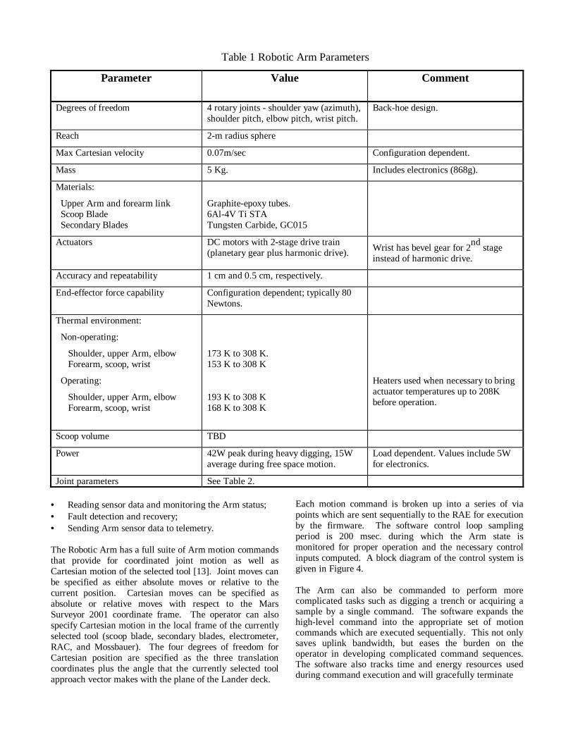
Table 1 Robotic Arm Parameters
Parameter Value Comment
Degrees of freedom 4 rotary joints - shoulder yaw (azimuth),shoulder pitch, elbow pitch, wrist pitch.
Back-hoe design.
Reach 2-m radius sphere
Max Cartesian velocity 0.07m/sec Configuration dependent.
Mass 5 Kg. Includes electronics (868g).
Materials:
Upper Arm and forearm link Scoop Blade Secondary Blades
Graphite-epoxy tubes.6Al-4V Ti STATungsten Carbide, GC015
Actuators DC motors with 2-stage drive train(planetary gear plus harmonic drive). Wrist has bevel gear for 2
nd stage
instead of harmonic drive.
Accuracy and repeatability 1 cm and 0.5 cm, respectively.
End-effector force capability Configuration dependent; typically 80Newtons.
Thermal environment:
Non-operating:
Shoulder, upper Arm, elbow Forearm, scoop, wrist
Operating:
Shoulder, upper Arm, elbow Forearm, scoop, wrist
173 K to 308 K.153 K to 308 K
193 K to 308 K168 K to 308 K
Heaters used when necessary to bringactuator temperatures up to 208Kbefore operation.
Scoop volume TBD
Power 42W peak during heavy digging, 15Waverage during free space motion.
Load dependent. Values include 5Wfor electronics.
Joint parameters See Table 2.
• Reading sensor data and monitoring the Arm status;• Fault detection and recovery;• Sending Arm sensor data to telemetry.
The Robotic Arm has a full suite of Arm motion commandsthat provide for coordinated joint motion as well asCartesian motion of the selected tool [13]. Joint moves canbe specified as either absolute moves or relative to thecurrent position. Cartesian moves can be specified asabsolute or relative moves with respect to the MarsSurveyor 2001 coordinate frame. The operator can alsospecify Cartesian motion in the local frame of the currentlyselected tool (scoop blade, secondary blades, electrometer,RAC, and Mossbauer). The four degrees of freedom forCartesian position are specified as the three translationcoordinates plus the angle that the currently selected toolapproach vector makes with the plane of the Lander deck.
Each motion command is broken up into a series of viapoints which are sent sequentially to the RAE for executionby the firmware. The software control loop samplingperiod is 200 msec. during which the Arm state ismonitored for proper operation and the necessary controlinputs computed. A block diagram of the control system isgiven in Figure 4.
The Arm can also be commanded to perform morecomplicated tasks such as digging a trench or acquiring asample by a single command. The software expands thehigh-level command into the appropriate set of motioncommands which are executed sequentially. This not onlysaves uplink bandwidth, but eases the burden on theoperator in developing complicated command sequences.The software also tracks time and energy resources usedduring command execution and will gracefully terminate
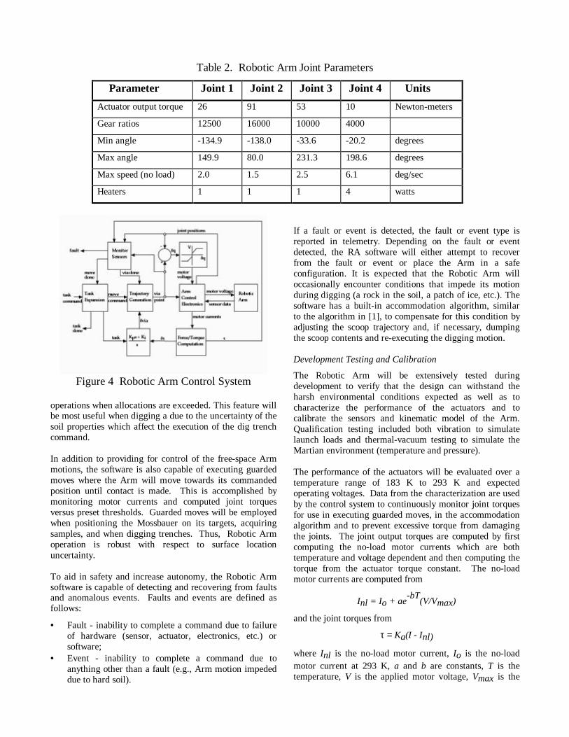
Table 2. Robotic Arm Joint Parameters
Parameter Joint 1 Joint 2 Joint 3 Joint 4 Units
Actuator output torque 26 91 53 10 Newton-meters
Gear ratios 12500 16000 10000 4000
Min angle -134.9 -138.0 -33.6 -20.2 degrees
Max angle 149.9 80.0 231.3 198.6 degrees
Max speed (no load) 2.0 1.5 2.5 6.1 deg/sec
Heaters 1 1 1 4 watts
Figure 4 Robotic Arm Control System
operations when allocations are exceeded. This feature willbe most useful when digging a due to the uncertainty of thesoil properties which affect the execution of the dig trenchcommand.
In addition to providing for control of the free-space Armmotions, the software is also capable of executing guardedmoves where the Arm will move towards its commandedposition until contact is made. This is accomplished bymonitoring motor currents and computed joint torquesversus preset thresholds. Guarded moves will be employedwhen positioning the Mossbauer on its targets, acquiringsamples, and when digging trenches. Thus, Robotic Armoperation is robust with respect to surface locationuncertainty.
To aid in safety and increase autonomy, the Robotic Armsoftware is capable of detecting and recovering from faultsand anomalous events. Faults and events are defined asfollows:
• Fault - inability to complete a command due to failureof hardware (sensor, actuator, electronics, etc.) orsoftware;
• Event - inability to complete a command due toanything other than a fault (e.g., Arm motion impededdue to hard soil).
If a fault or event is detected, the fault or event type isreported in telemetry. Depending on the fault or eventdetected, the RA software will either attempt to recoverfrom the fault or event or place the Arm in a safeconfiguration. It is expected that the Robotic Arm willoccasionally encounter conditions that impede its motionduring digging (a rock in the soil, a patch of ice, etc.). Thesoftware has a built-in accommodation algorithm, similarto the algorithm in [1], to compensate for this condition byadjusting the scoop trajectory and, if necessary, dumpingthe scoop contents and re-executing the digging motion.
Development Testing and Calibration
The Robotic Arm will be extensively tested duringdevelopment to verify that the design can withstand theharsh environmental conditions expected as well as tocharacterize the performance of the actuators and tocalibrate the sensors and kinematic model of the Arm.Qualification testing included both vibration to simulatelaunch loads and thermal-vacuum testing to simulate theMartian environment (temperature and pressure).
The performance of the actuators will be evaluated over atemperature range of 183 K to 293 K and expectedoperating voltages. Data from the characterization are usedby the control system to continuously monitor joint torquesfor use in executing guarded moves, in the accommodationalgorithm and to prevent excessive torque from damagingthe joints. The joint output torques are computed by firstcomputing the no-load motor currents which are bothtemperature and voltage dependent and then computing thetorque from the actuator torque constant. The no-loadmotor currents are computed from
Inl = Io + ae-bT
(V/Vmax)
and the joint torques from
τ = Ka(I - Inl)
where Inl is the no-load motor current, Io is the no-loadmotor current at 293 K, a and b are constants, T is thetemperature, V is the applied motor voltage, Vmax is the

maximum operating voltage, τ is the torque, I is the motorcurrent, and Ka is the actuator torque constant. Theconstants a, b, and Io are determined from the test data byusing a least-squares fit. During the landed mission, astandard set of free-space moves will be periodicallyexecuted to monitor actuator performance. In addition, thejoint heaters will be operated to characterize the thermalproperties of the joints in the Martian environment.
Calibration of the Arm position sensors and kinematicmodel will be done moving the Arm through a series ofposes throughout the workspace and measuring the locationof the end effector using a system of highly accuratetheodolites. The sensor and kinematic model parameterswill t hen be determined by solving a constrainedminimization problem which minimizes the mean errorover the measured poses. The kinematic model parametersare based on the method of Denavit and Hartenberg [2].
During digging and soil-mechanics experiments, estimatesof forces exerted by the end-effector tools are importantdata for use in determining soil properties. These estimatescan be made from the sensed motor currents, but will besomewhat crude due to unmodeled Arm dynamics and thelimited degrees of freedom of the Arm. During digging andsoil mechanics experiments, reaction from the soil canexert forces on the end effector which cannot be detected atthe Arm joints via the sensed motor currents due to thelimited degrees of freedom and the fact that all of themotors are not on at all times during Arm motion. End-effector forces can be estimated from
Fe = JT#τ
where Fe is the force vector exerted by the end effector,
JT#
is the pseudoinverse of the manipulator Jacobian [10]transpose with the rows associated with the unactuatedjoints removed, and τ is the vector of joint torques for the
actuated joints. End-effector forces in the null space of JT
will not appear in the joint torques. The manipulatorJacobian is dependent on Arm configuration and, thus, thetransformation to end-effector forces and the null spacechanges as the joint angles change.
Experimental Investigations
Data acquired as part of the physical properties experimentswill come from many sources. A majority of the RAoperations will be in support of the primary missionobjectives including: digging, dumping, acquiring samples.Although these activities will not be performed specificallyto provide materials properties data, by tailoring theoperational sequences carefully it will be possible toleverage this data with that from other instruments to gainadditional insight. For example, by maintaining a constantdump location for a few hours of operation while digging atrench, a rather sizable conical pile can be obtained. Inorder for this pile to be useful for observing changes over
time, it should be in an isolated area, which necessitatesmoving the dump location for future digging to anotherarea. This means extra effort in managing the availableworkspace as a resource, as well as the additional wear onthe actuators for the additional movement, but thesupplementary data necessitates the effort.
In addition to the data gained during regular Armoperations, specific materials properties experiments will beperformed (see Table 3). Because of the criticality of theefficient operation of the Arm to support the rest of thescience objectives (particularly acquiring samples for theMECA) , dedicated materials properties experiments willbe done based on available resources. However, even underadverse conditions it should be possible to perform asubstantial number of dedicated experiments. Thefollowing is a partial li st of some of the physical propertiesexperiments that will be conducted:
a) Scoop blade insertion to determine soil penetrationresistance.
b) Scraping with the scoop blade and the secondary blades.The cutting ability of the different cutting tools willyield information on the cohesion of the soil. Close-upimaging of wear on the scoop blade will provide grainstrength data. If the opportunity is presented, rockswithin the workspace will be abraded using the tools onthe scoop.
c) Intentionally causing the trench to cave in. By under-cutting the wall of the trench or by using the under sideof the scoop to apply pressure at the surface next to theedge of the wall it will be possible to cause a trench wallto cave in under controlled conditions, yielding bearingstrength data.
d) Chopping soil samples. The ability of the Arm torepeatedly chop a sample in preparation for MECAdelivery will provide cohesion data
e) Shaking the end effector. Because of the flexibility andlength of the Arm it is possible to create repeatableagitations to shake loose particles, allowing for insightinto particle adhesion.
f) Excavated soil piles. Long term data will be gatheredby monitoring the evolution of purposefully placedconical excavated soil piles.
The primary operations tool for commanding the Mars ’01Robot Arm will be the Web Interface for Telescience(WITS) system. WITS provides target designation frompanorama image data, generates command subsequencesvia programmed macros, simulates arm motion, checks forcollisions, computes resources (energy, time, data), andoutputs a complete command sequence file for uplink to theLander.
Data Products
The Robotic Arm subsystem generates two kinds oftelemetry - engineering and science. Engineering telemetryconsists of current Arm state data which is downlinked atthe completion of each Robotic Arm command. Science

Table 3. Soil Properties Experiments
Property Task
Adhesion Imaging of scoop and patch plate.
Angle of internal friction Surface bearing tests using bottom of scoop, imaging footpads.
Angle of repose Imaging of natural slopes, trench walls, tailing piles.
Bearing Strength and Cohesion Imaging of footpads and trench wall.
Bulk Density Imaging of footpads.
Chemical Compositions MECA analysis.
Grain size distribution RAC imaging and MECA sorting on screen before and aftervibration
Heterogenity RAC imaging, Arm forces while digging.
Penetration resistance Scoop blade insertion.
telemetry consists of detailed sensor data collected every200 milliseconds during command execution. Robotic Armscience telemetry is used for reconstruction of the diggingprocess, soil-mechanics experiments and for troubleshooting.
The following engineering data is reported to the telemetrysystem at the completion of each Robotic Arm command(except where noted):
• Command op code;• Joint position from encoders (radians);• Joint position from potentiometers (radians);• Joint temperatures (degrees Celsius);• Sum of heater currents (amps, reported upon change);• Energy consumed (watt-hours);• Voltage references (volts);• Health status (reported upon fault or event)
While the Arm is moving, raw Arm sensor data iscollected every 200 milliseconds and stored for subsequentdownlink in telemetry. All analog data is converted to 12-bit digital format. The following raw digitized data iscollected:
• Joint angle encoder count;• Joint angle potentiometer voltage;• Joint temperatures;• Motor currents;• Motor voltages;• Status word (motor, brakes, and heater state
information)• Sum of heater currents;• Time.
The Robotic Arm science telemetry will be the most usefulfor scientific analysis of soil properties during digging andsoil-mechanics experiments. The motor currents along
with the reconstructed Arm trajectories will yieldinformation regarding the degree of difficulty of digging inthe various soils encountered and of executing the Armmotions during the various soil-mechanics experiments. Inaddition to the data listed above, detailed history of theArm state and control variables for the last one minute ofoperation is downlinked whenever a fault or event occurs.This will permit reconstruction of the exact sequence ofevents leading to the anomaly.
The following data will be archived in the Planetary DataSystem (http:pds.jpl.nasa.gov) for use by the sciencecommunity:
• Position data for the RAC;• Joint positions, temperatures and motor currents for
reconstruction of Arm trajectories and joint torques;• Calibration report;• Experimenter’s notebook.
3. ROVER
The Marie Curie rover (Figures 5 & 6) is a six-wheeledvehicle 68 cm long, 48 cm wide, and 28 cm high (with 17cm ground clearance). The body is built on the rocker-bogie chassis, which, by use of passive pivot arms, allowsthe vehicle to maintain an almost constant weightdistribution on each wheel on very irregular terrain. As aresult, the rover is able to traverse obstacles about 1.5times as big as the wheels, since the rear wheels are able tomaintain traction even while pushing the front wheels intovertical steps hard enough to get li fting traction. Thisconsists of linkages, six motorized wheels, and fourmotorized-steering mechanisms. The four corneredsteering mechanisms allow the rover to turn in place. Thevehicle's maximum speed is about 0.7 cm/sec. Since thedesign of the Marie Curie is very similar to that of theSojourner, more details of the design and implementationcan be found in [5], [11], and [12]. If the rover ball andwire cannot disengage from the Arm crowfoot during the

rover deployment, a pin puller mechanism is mounted atthe center of the rover solar panel, and it can be releasedby an operator command.
Figure 5 The Marie Curie Rover
Figure 6 The Rover Assembly
Electronics
The rover is controlled by an Intel-8085 CPU operating at2MHz (100KIPS). The on-board electronics are customdesigned in order to meet the flight requirements and to fitinto a small Warm Electronics Box (WEB). The on-boardmemory, addressable in 16 Kbyte pages, includes 16 Kbyterad-hard PROM, 176 Kbyte EEPROM, 64 Kbyte rad-hardRAM and 512 Kbyte RAM. The navigation sensorsconsist of a rate gyro, 3 accelerometers for sensing the X,Y, and Z axis motion, and 6 wheel encoders for odometry.Articulation sensors include differential and left and rightbogey potentiometers. Wheel steering and APXS (Alpha-Proton X-Ray Spectrometer) positions are monitored by 5potentiometers. All motor currents and the temperaturesof vital components are also monitored.
The two front black and white CCD cameras (768 x 484pixels) provide hazard detection and science/operationimaging. The rear color CCD camera is used for scienceimaging and APXS target verification. A suite of five
infrared laser stripe projectors, coupled with the front CCDcameras, provide the proximity sensing and hazarddetection capability for the vehicle. This system operatesby locating the image of the laser stripes on a few selectedscan lines of the camera images. Deviations of the detectedlocations from the nominal flat-terrain values indicate thatthe terrain is uneven. An array of elevation values iscreated from the stripe-camera intercepts. Proximityhazards are detected when elevation differences betweenadjacent points in the array exceed a threshold, or when thedifference between the highest and lowest point in the arrayexceeds a threshold. Other hazards include excessive rollor pitch, or excessive articulation of the chassis, or contactwith bump sensors on the front or rear of the vehicle.
A bi-directional UHF radio modem (9600 bits/second)allows the vehicle to transmit telemetry and to receivecommands from Earth via the Lander. The vehicle ispowered by a 15-watt gas solar panel backed up in case offailure by a non-rechargeable Lithium battery. This batteryis also used for nighttime APXS operations.
Rover Navigation
The rover is operated on the basis of a fixed localcoordinate frame with origin at the center of the Landerbase and the X and Y axes pointed to Martian North andEast (right-hand rule), respectively (Martian North isdefined by the Lander sun finder). The vehicle's X,Ypositions are calculated (at ~2 Hz rate) by integrating itsodometer (average of the six wheel encoder counts) withthe heading changes produced by the rate gyro. Due to thelow processor speed and lack of floating point arithmetic,millimeter (mm) and Binary Angle Measurement (BAM)are used as distance and turn angle units respectively (1Deg = 182 BAM or 360 Degs = 65,536 BAM). Whilemoving, the vehicle monitors its inclination, articulation,contact sensing, motor and power currents, andtemperatures to be sure they did not exceed limit conditionsbased on risk level settings. Being too close and headingtoward Lander conditions are also monitored. The roverperiodically sends a heartbeat signal to the Lander at onevehicle-length intervals. In the absence of thiscommunication signal, the vehicle is autonomously backedup half of its length and a communication retry takes place.The rover motion is commanded by one of the followingcommands: Turn, Move, Go to Waypoint, Find Rock , andPosition APXS.
The Turn command in general causes the vehicle to changeits heading in place. The four steered wheels are adjustedinto their appropriate positions, then the vehicle wheels areturned until the desired heading, indicated by integratingthe rate gyro, is met. The rover completes a turn when thegyro heading is in within +/- 1.5 degrees of the desiredheading. In case the gyro is disabled, the odometry is usedto calculate the heading changes; if both the gyro andodometer are disabled, timing is used in the calculation.The Turn To command causes the vehicle to turn to a

specific heading, while the Turn By command causes thevehicle to turn to a relative heading. The Turn Atcommand causes the vehicle to turn so as to point to aspecific X,Y position.
The Move command enables the vehicle to move for aspecified distance, using only odometry and no hazardavoidance. This "blind move" is useful when the terrain isclearly seen by the operator (in images from the Lander)and the move is a short one. The Set Steering Positionparameter of the Move command determines the arc radiusof the move. The rover completes a move once the averagesix- wheel encoder count exceeds the desired encodercount. Parts of the distance errors are due to the wheelslippage, and they depend on the terrain the vehicletraverses.
The Go to Waypoint command causes the vehicle totraverse to a specified X,Y location. The vehicle drivesforward a distance of one wheel radius and stops for laserproximity scanning. A terrain height map is constructedinternally from the information provided by the lasers andCCD imagers. If an obstacle is detected on the left, thevehicle will t urn right, and visa versa. A flag is set whichindicates the direction of the turn, and the vehicle willcontinue turning by increments until a hazard-free zone atleast as wide as the vehicle is detected by the laser scanningsystem. If the clear zone is wider than the vehicle turningcircle, then the rover drives straight ahead far enough tobring the obstacle alongside. Then the rover begins an arctoward the goal point, clears all memory of the hazardavoidance maneuver, and continues. If the clear zone isnarrower than the vehicle- turning circle (but wider thanthe vehicle) then a "thread-the-needle" maneuver isattempted. This maneuver centers the rover on theperpendicular bisector between the two hazards, and movesstraight ahead along that line until a zone that is bigenough to turn around is detected. Once such a zone isdetected, all memory of the maneuver is deleted and therover begins an arc toward the goal. If an obstacle isencountered prior to detection of a free turning circle, thenthe rover backs straight out to the point where the thread-the-needle maneuver began, and the rover continues to turnuntil another hazard-free zone is detected. Arcs toward thegoal are calculated to three values: if the rover is alreadypointed toward the goal (within a small deadband) then therover goes straight, if the rover heading is outside thatdeadband but less than about 1 radian, then a large-radiusturn (about 2 meters) is begun which turns toward the goal,and if the heading is more than 1 radian from the goaldirection, then a short radius turn (about 1 meter) is begunwhich turns toward the goal. Note that a turn in placemaneuver is not used here, since that would cause the roverto become trapped in "box canyons" whereas the presentalgorithm does not.
The Find Rock command is very similar to the Go toWaypoint command, except that after a hazard is detectedat approximately the X,Y position of the waypoint, then the
rover centers its heading between the edges of the rockusing proximity sensing. If the destination coordinates arereached without any rocks found along the way, a spiralsearch is performed until the rock is found.
In both Go to Waypoint and Rock Finding commands, therover reaches its destination when dX * dY < 100 mm2; dXand dY are distances from the vehicle to its target positionin X and Y respectively. In case the rover can not get to itsdestination due to an obstacle at the destination, the roverdeclares a successful command completion when it comeswithin 500 mm2 of the target destination. The vehiclemonitors the progress of the Go to Waypoint and Find Rockcommands and enforces a time limit (which is a parameterof the command).
The Position APXS command enables the vehicle to movebackward until the APXS sensor head contacts the rock thathas been found or until the maximum allowable distancehas been reached without contact or time-out.
For every uplink command, the vehicle sends either anacknowledge message or the telemetry collected duringexecution of the commands, including any error messages.Navigation telemetry in general contains the time tag, thecommand sequence number, the current X,Y and headingvalues, steering positions, inclination and articulationvalues, motor currents, temperatures, and contact andencoder information. In addition, the Go to Waypoint andFind Rock telemetry data also include the obstacle heightmap provided by the proximity and hazard avoidancemechanism for every 6.5 cm of traverse.
The health checks telemetry provides a snapshot of thecurrent status of the vehicle. In addition to almost all of thenavigation information, the power supply current andvoltage status, individual wheel odometer readings,communication error counts, device fail counts, min/maxaccelerometer values, motor current values, and averagemotor currents of the last traversal are reported here. Otherrover telemetry data is designed to report data from science,engineering experiments and rover housekeeping utilities.
The rover also has the ability to adjust its positionknowledge based on the assessment of the Lander using theLander Based Autonomous Localization (LBAL) algorithm.For every heartbeat which the rover sends to the Landerduring Go to Waypoint or Find Rock command execution,the Lander’s response will be based on whether the LBALfunction is active or not. If the Lander’s LBAL function isnot active, the rover will continue on with its navigationtask. Otherwise, the Lander will request the rover to waitfor the Lander to send to the rover the updated positioninformation. The Lander uses the rover positioninformation from the heartbeat message to capture a stereopair of images with its cameras pointing toward the generalarea where the rover has stopped. The Lander’s on-boardLBAL algorithm will estimate the current rover positionbased on these images, and will send this new rover

position information to the rover for updating. At any timein between commands, the operator can also request therover to update its position by sending a LBAL requestcommand to the rover. Subsequently, the rover will performa heartbeat session to get its new position from the Lander.
The Rover Control Station
Human operators using the Rover Control Workstation(RCW) indirectly control the rover. The RCW'scustomized graphical user interface software provides toolsfor the operator to generate commands with parameterchecking capabilities and to designate waypoints in a 3-Dimage display. A command sequence which comprisesmultiple commands is built based on requests from thescientists, vehicle engineering telemetry, and the end-of-solstereo images captured by the Lander cameras. The rover3-D icon shown on the RCW display allows the operator toassess traverse ability by placing the icon over a 3-DMartian terrain image set at any position and orientation.The rover’s current position and heading are also acquiredby matching the icon with the rover’s physical position inthe stereo images. This capability allows the operator to re-initialize the vehicle’s true position and orientation at thebeginning of a sol. In Go to Waypoint designation, theoperator specifies the rover destinations by placing therover 3-D cursor at each waypoint, then clicking the mouseto identify these destinations. The RCW records thesewaypoints and generates the Go to Waypoint commandsautomatically. Other commands are generated fromoperator-specified parameter values, and the commandsequence file is created. The accuracy of the designationdepends on the distance between the stereo cameras, imageresolution, and human designation ability. The overallaccuracy of the designation was estimated at about 2 to 3percent for cross and down ranges and for heading.
The Science Instruments
There will be three science instruments mounted on-boardthe rover: The Alpha Proton X-ray Spectrometer (APXS),the Mars Experiment on Electrostatic Charging (MEEC),and the Wheel Abrasion Experiment (WAE) instruments.
The APXS instrument [8] is designed to obtain thechemical composition of Martian rocks and soil. The APXSuses three kinds of interactions of the alpha particles froma radioactive source with matter: Rutherford backscattering(alpha mode), nuclear reactions of alpha with some lightelements (proton mode), and generation of characteristic x-ray in the sample through ionization by alpha particles (x-ray mode). Three energy spectra obtained from theseinteractions are recorded in three different channels. In thealpha mode, the APXS can measure all chemical elements,which are heavier than helium. Sensitivity is excellent forlight elements such as C, H and O. In the x-ray mode, itmeasures all elements which are heavier than Na. Theinstrument includes a sensor head and an electronic box.The sensor head is mounted to the APXS DeploymentMechanism (ADM). Through a command from the
operator, the ADM enables the APXS sensor head to beplaced closer to but not contacting the experimental rock orsoil. The APXS electronic unit serves as an interfacebetween the APXS sensor head and the rover on-boardcomputer system. The electronic unit receives commandsfrom the rover computer and sends appropriate signals tothe sensor head. The electronic unit also accumulatesAPXS sensor head data before sending back to the rovercomputer. The PIs of this instrument are from the Max-Planck-Institute fur Chemie, Mainz, Germany and from theEnrico Fermi Institute, University of Chicago, Chicago.
The Material Experiment on Electrostatic Charging(MEEC) experiments consists of two components: theWheel Abrasion Experiment (WAE) and the measurementof the charges during a rover traversal by means of thepotential the rover attains during the movement.
The first MEEC component, the WAE instrument [3],Figure 7, is designed to measure how much adhesive andabrasive the Martian dust would be on strips of pure metalattached to one of the rover wheels. Fifteen thin filmsamples (five each of three different metals) which areattached to the wheel periphery reflect sunlight to aphotovoltaic sensor. The wheel rotation enables thepresentation of the different sample surfaces to the sensor.The resulting signals are recorded using the rover computerand are interpreted in terms of dust adhesion and abrasivewear.
Figure 7 Reflective wheel (left) for WAE instrument
The second MEEC component consists of a groundreference watchplate mounted at the front left corner of therover solar panel, and an electronic board for collectingdata. A 100-microCurie Americium 241 dot resides on thewatchplate and will be used to ionize some of the Martianatmosphere to "ground" itself to Mars. The potential theMarie Curie rover attains during a traversal (or overnightor Martian wind) with respect to the "ground" referencewill be measured by the electronic board residing inside theWEB. The potential difference between this dot and theRover chassis will be measured in terms of nanoAmpcurrent, which flows when the two are connected. Thiscurrent will be time integrated to acquire a value ofelectrical charge. This value will then be used together with

the measured rover capacitance to estimate the roverelectrical potential relative to the charge cloud. Thecollected data will be converted to a digital format fortransmission back to earth for study. The PIs of the MEECare from the NASA Glen Research Center, Cleveland,Ohio.
4. CONCLUSION
The Mars Surveyor 2001 Robotic Arm is an essentialelement in carrying out the Mars Surveyor 2001 scienceexperiments. In support of the other instruments, it willdig trenches in the Martian soil, deliver soil samples to theMECA, and position the Mossbauer and the RAC. TheRobotic Arm will also conduct Arm-specific scienceexperiments to collect data relating to soil properties suchas periodic imaging of dumped soil piles, surface scrapingand soil chopping experiments, compaction tests, insertionof the scoop blade into the soil, scoop shake tests andtrench cave-in tests. Key data elements include joint motorcurrents and trajectories which will be used to estimate end-effector forces during Arm operations. Data from theRobotic Arm support operations and science experimentswhen combined with data from the other instruments willyield important information on Martian soil properties,providing valuable insight into the history of Mars.
Although the Marie Curie rover is almost identical to theSojourner rover, which landed on Mars in 1997, manyimprovements have been made to prepare for the upcomingmission. The rover mechanical and electronics hardwarehave been refined. The rover’s gyro and accelerometerperformances have been improved significantly in terms ofaccuracy and reliability. The rover software has beenmodified to cope with the new requirements in the areas ofcommunication, landing and deployment profile, LBAL,pin puller and MEEC instrument. Some time in January of2002, the Marie Curie rover will visit a whole new area onMars in the vicinity of the Lander’s landing site. The roverhas the abilities of traversing to designated sites, ofexamining soil and rocks using its on-board scienceinstruments, and of capturing images of interest sites atclose range or from distance. These sites could be far awayfrom the contaminants, which may have been caused by theLander propulsion system at the landing site. The collectivedata from the rover will be analyzed and these will bring usup-to-date knowledge at another part of the Martian surfacewhich we have never visited before.
ACKNOWLEDGEMENT
The research described in this paper was carried out by theJet Propulsion Laboratory, California Institute ofTechnology, under a contract with the NationalAeronautics and Space Administration.
References
[1] Bonitz, R.G. and Hsia, T.C., “Robust Internal Force-tracking Impedance Control for Coordinated Multi-ArmManipulation - Theory and Experiments”, Proceedings ofthe 6th International Symposium of Robotics andManufacturing, 2nd World Automation Congress, May 1996
[2] Denavit, J. and Hartenberg, R.S., “A KinematicNotations for Lower Pair Mechanisms,” J. AppliedMechan1ics, Vol. 22, pp. 215-221, 1955
[3] Ferguson, D. C., Kolecki, J. C., Siebert, M. W., Wilt, D.M., Matijevic, J. R., “Evidence for Martian electrostaticcharging and abrasive wheel wear from the WheelAbrasion Experiment”, Journal of Geophysical Research,Vol 104. No. E4, pages 8747-8789, April, 25, 1999.
[4] Holmberger, N.A., Faust, R.P. and Holt, H.M., “Viking‘75 Spacecraft Design and Test, Summary Volume 1”,NASA Reference Publication 1027, pp. 174-180, 1980
[5] Matijevic, J. R., "Mars Pathfinder Microrover -Implementing a Low Cost Planetary Mission Experiment",Proceedings of the Second IAA International Conferenceon Low Cost Planetary , John Hopkins University, AppliedPhysics Laboratory, Laurel, Maryland, April 1996.
[6] Mishkin, A. H., J. Morrison, T. Nguyen, H. Stone,B.Cooper, B. Wilcox, "Experiences with Operations andAutonomy of the Mars Pathfinder Microrover",Proceedings of the 1998 IEEE Aerospace Conference,March 21-28, Snowmass at Aspen, Colorado.
[7] Moore, H.J., Hutton, R.E., Clow, G.D. and Spitzer G.E.,“Physical Properties of the Surface Materials at the VikingLanding Sites on Mars”, U.S. Geological SurveyProfessional Paper 1389, 1987
[8] Rider, R., Economu, T., Wanke, H., Turkevich, A.,Crisp, J., Buckner, J., Dreibus, G., McSween Jr., H. Y.,“The Chemical Composition of Martian Soil and RocksReturned by the Mobile Alpha Proton X-Ray Spectrometer:Preliminary Results from the X-Ray Mode”, Science,December 1997, Vol. 278 – page 1771-1774.
[9] P. S. Schenker, D. L. Blaney, D. K. Brown, Y. Bar-Cohen, S-S. Lih, R. A. Lindemann, E. D. Paljug, J. T.Slostad, G. K. Tharp, C. E. Tucker, C. J. Voorhees, and C.Weisbin, Jet Propulsion Lab.; E. T. Baumgartner, Mich.Tech. Univ.; R. B. Singer, R. Reid, Univ. of Arizona,"Mars Lander robotics and machine vision capabilities forin situ planetary science," in Intelligent Robots andComputer Vision XIV, SPIE Proc. 2588, Philadelphia, PA,October, 1995.
[10] Spong, M.W. and Vidyasagar, M., “Robot Dynamicsand Control”, John Wiley and Sons, pp. 111-119, 1989
[11] Stone, H. W., "Mars Pathfinder Microrover: A Low-Cost, Low-Power Spacecraft", Proceedings of the 1996AIAA Forum on Advanced Developments in SpaceRobotics, Madison, WI, August 1996.

[12] Stone, H. W., "Design and Control of theMESUR/Pathfinder Microrover", Proceedings of theInternational Conference on Advanced Robotics, Tokyo,Japan, November 1993.
[13] Taylor, R., “Planning and Execution of Straight-lineManipulator Trajectories”, IBM Journal of Research andDevelopment, Vol. 23, No. 4, pp. 424-436, 1979
Robert Bonitz is currently with theTelerobotics Research and Applications Group at the JetPropulsion Laboratory where he recently designed anddeveloped the control algorithms and software for the MarsVolatiles and Climate Surveyor Robotic Arm inherited for useby the Mars 2001 Lander Robotic Arm. Previously, he hasconducted research in control algorithms for multiple-manipulator robotic systems, robust internal force-basedimpedance controllers, frameworks for general forcedecomposition, optimal force control algorithms, andcalibration methods for multi-arm robotic systems. He hasworked for a variety of industrial companies includingRaytheon, TRW, Source 2 International, and GTE. He has aPhD in Electrical Engineering from the University ofCalifornia, Davis.
Won S. Kim received the Ph.D. degree inelectrical engineering and computer sciences from theUniversity of California, Berkeley, in 1986. He has been withthe Jet Propulsion Laboratory, Pasadena, CA, since 1988. Hereceived Franklin V. Taylor Award in 1988 IEEE Conferenceon System, Man, and Cybernetics, and published more than50 journal and conference papers in the telerobotics area.
Tam Nguyen is a software engineer forthe Robotic Vehicles Group at the Jet PropulsionLaboratory, Pasadena, California. Currently, he is thesoftware lead for the Microrover of the 2001 MarsSurveyor Project. Prior to this, he was a Microrover'ssoftware team member and a Microrover Downlink DataAnalysis team member of the Mars Pathfinder Project.Since 1988, he had developed software and integratedhardware in the areas of motion control, and navigationfor several planetary rover research programs. Prior tothese programs, he was a software team member of theTelerobotics Research Project, and of the RoboticsTechnology Test Vehicle Research Project. He was a keysoftware engineer for the Three Axis Acoustic LevitatorProject, a physics experiment flown on-board the Shuttle.Nguyen holds a BS in Physics and Chemistry and aMSEE from CSU Long Beach, California.