2010 oregon state university mars rover design...
TRANSCRIPT

2010 Mars Rover Design Report Oregon State University Edited by Florian Kapsenberg
Team Lead: Jonathan Doltar
Lead Mechanical Engineer: Florian Kapsenberg
Lead Robotic Arm Engineer: Joe Hortnagl
Lead Electrical Engineer: Tyler Slone
Lead Software Engineer: Taj Morton
Lead Scientist: Shannon Cahill-Weisser
1
Table of Contents
Review of 2009 Mars Rover ....................................................... 2
The 2010 Mars Rover ................................................................ 3
Team Organization and Management ........................................ 4
Rover Mechanics ....................................................................... 5 Wheels ......................................................................................... 5 Chassis .......................................................................................... 6 Steering Information .................................................................... 7 Actuators ...................................................................................... 7 The Frame .................................................................................... 7 Bogie Hinges ................................................................................ 8 Chassis Stress Analysis ................................................................. 9 Robotic Arm ............................................................................... 10 Arm Stress Analysis .................................................................... 11 Manufacturing the 2010 Mars Rover ........................................ 11 Camera placement ..................................................................... 13
Rover Electronics ..................................................................... 13 Power Systems & Electronics ..................................................... 14 Radio Frequency Communications ............................................. 16 Navigation .................................................................................. 17 PCB Backplane ........................................................................... 17 Camera & Video Systems ........................................................... 17 Motors & Motor Control Systems .............................................. 19 Servo Control .............................................................................. 20 Linear Actuator Control .............................................................. 21
Rover Software ....................................................................... 21 USB Communication .................................................................. 22 Embedded Linux Controller ........................................................ 22 Rover Software Design ............................................................... 22 Data Communication Protocol ................................................... 22 Control Interface Design ............................................................ 23 Task Assistance .......................................................................... 23 Rover Control ............................................................................. 24
Science .................................................................................... 25 Site Selection Parameters .......................................................... 25 Returned Sample Analysis .......................................................... 26 Data Presentation and Documentation ..................................... 27 Science References ..................................................................... 27
Conclusion .............................................................................. 28
Thanks to our sponsors ........................................................... 29
2
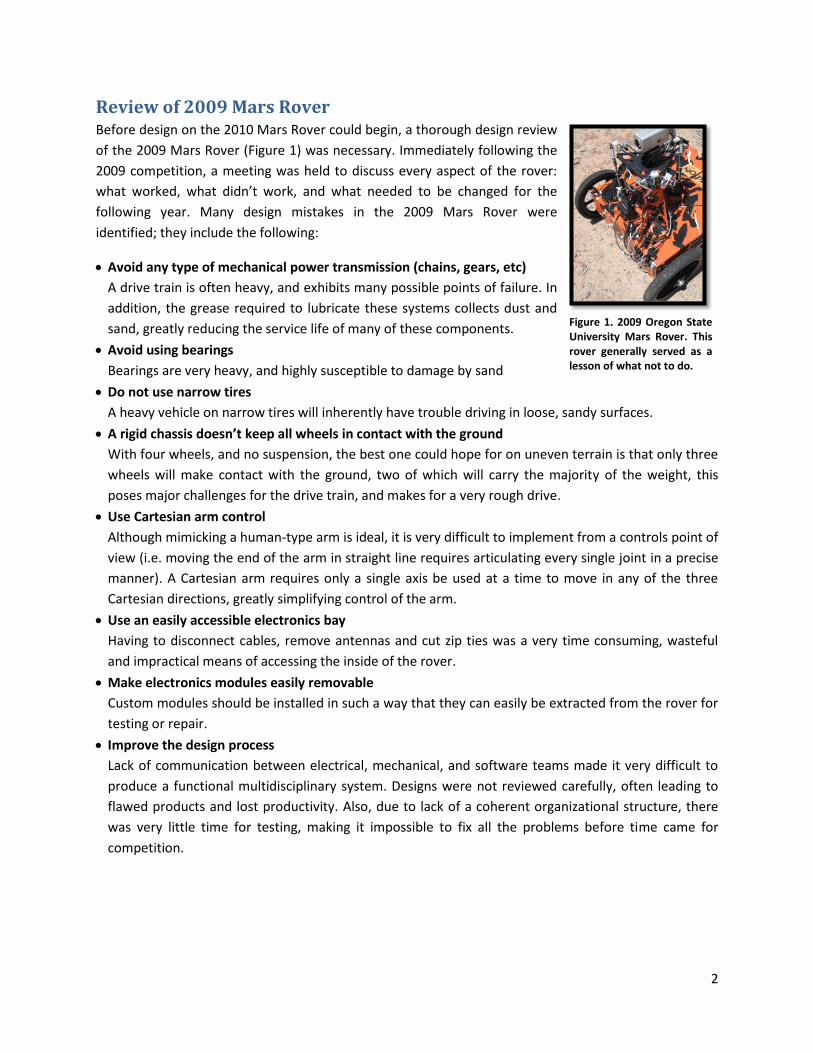
Review of 2009 Mars Rover Before design on the 2010 Mars Rover could begin, a thorough design review
of the 2009 Mars Rover (Figure 1) was necessary. Immediately following the
2009 competition, a meeting was held to discuss every aspect of the rover:
what worked, what didn’t work, and what needed to be changed for the
following year. Many design mistakes in the 2009 Mars Rover were
identified; they include the following:
Avoid any type of mechanical power transmission (chains, gears, etc)
A drive train is often heavy, and exhibits many possible points of failure. In
addition, the grease required to lubricate these systems collects dust and
sand, greatly reducing the service life of many of these components.
Avoid using bearings
Bearings are very heavy, and highly susceptible to damage by sand
Do not use narrow tires
A heavy vehicle on narrow tires will inherently have trouble driving in loose, sandy surfaces.
A rigid chassis doesn’t keep all wheels in contact with the ground
With four wheels, and no suspension, the best one could hope for on uneven terrain is that only three
wheels will make contact with the ground, two of which will carry the majority of the weight, this
poses major challenges for the drive train, and makes for a very rough drive.
Use Cartesian arm control
Although mimicking a human-type arm is ideal, it is very difficult to implement from a controls point of
view (i.e. moving the end of the arm in straight line requires articulating every single joint in a precise
manner). A Cartesian arm requires only a single axis be used at a time to move in any of the three
Cartesian directions, greatly simplifying control of the arm.
Use an easily accessible electronics bay
Having to disconnect cables, remove antennas and cut zip ties was a very time consuming, wasteful
and impractical means of accessing the inside of the rover.
Make electronics modules easily removable
Custom modules should be installed in such a way that they can easily be extracted from the rover for
testing or repair.
Improve the design process
Lack of communication between electrical, mechanical, and software teams made it very difficult to
produce a functional multidisciplinary system. Designs were not reviewed carefully, often leading to
flawed products and lost productivity. Also, due to lack of a coherent organizational structure, there
was very little time for testing, making it impossible to fix all the problems before time came for
competition.
Figure 1. 2009 Oregon State University Mars Rover. This rover generally served as a lesson of what not to do.
3
The 2010 Mars Rover The lessons learned from the 2009 Mars Rover served as a design guideline for the 2010 Mars Rover.
Before going into detail about the rover’s systems, a brief overview will demonstrate how these lessons
helped define the design of the 2010 Mars Rover. The prominent design features of the 2010 Mars
Rover are the following:
Six wheels with balloon tires
Placing the rover on six balloon tires distributes the weight over a very large area, making it easy to
drive in sand and improves the skid-steer performance. In addition, the close spacing greatly reduces
the risk of becoming high-centered between wheels.
Direct drive
Each wheel has a dedicated motor to which it is directly mounted, eliminating the need for additional
shafts, sprockets, chains and bearings, reducing overall weight and complexity. Additionally, placing
the motors inside the wheels locates some of the heaviest components very close to the ground,
lowering the center of gravity, thereby improving the rover's ability to navigate steep terrain without
the risk of toppling over.
Flexible chassis with high ground clearance
This reduces the chance of becoming high-centered on obstacles, and insures all six wheels stay on the
ground, greatly improving all-terrain performance. The type of chassis employed does not require any
springs, bearings, or shock absorbers, greatly reducing complexity and improving reliability.
Non-skid-steer turning ability
By being able turn in place without skidding greatly increases the rover’s all-terrain capability as it no
longer requires smooth or loose surfaces to turn on; it is capable of turning over large, complex
obstacles.
Ergonomic electronics bay
If the electronics require troubleshooting or repair, the entire electronics bay can be removed from
the chassis with a few wing nuts. This allows the electrical and mechanical teams to simultaneously
work on their systems in separate locations. For example, machining work can be performed on the
chassis while the electronics bay is in the lab for installation or testing of electrical systems. The
electronics bay can be accessed by popping two latches and removing the cover. This saved a lot of
time during testing, and allowed for full functionality of the rover while the systems inside could be
tested. Additionally, each of the custom designed electronics modules were mounted in the rover via
a back plane. If a module required testing or fixing, it could simply be pulled out of its slot without the
need of tools or the removal of wires. Modules could also be re-installed without the possibility of
installing it incorrectly.
Adjustable height camera mast
The use of a tripod allows the camera to quickly be located anywhere over the rover, providing any
point of view desirable.
Protecting the electronics form the elements
Since much of our testing takes place in Oregon, it is necessary that that rover can withstand the
occasional precipitation. This was done by employing high quality weather-resistant connectors, a
sealed electronics bay, and minimizing the number of exposed connections by sealing them with heat

4
shrink. Also, it must be kept in mind that the rover is to drive in unpredictable environments. Dangling
wires are highly susceptible to being pulled out when driving in the outdoors. Eliminating dangling
wires greatly improves the reliability of the rover by preventing cables and wires from becoming
caught in motors, hinges, gears, and external objects such as branches, rocks, etc. Dangling wires were
avoided by combining wires into a wiring harness, wrapped in braided sleeving or spiral loom.
Furthermore, wherever possible, the wiring harness was placed inside of the hollow frame of the
chassis. Embedding the wiring harness ensured that nothing could physically affect the electrical
wiring.
Team Organization and Management Based on the organizational problems encountered during the design of the 2009 Mars Rover, a
complete overhaul of how the team was managed took place. The overall success of the 2010 Mars
Rover team is due to greatly improved organization and communication, a high level of excitement
towards the end goal, and a strict, yet reasonable timeline to get there.
In order to keep everyone up to date with the current state
of the project, a wiki was used (Figure 2). A wiki is a webpage
that is easily edited by all team members. Every design
category had its own page to which anyone could contribute.
Documentation was very important; the wiki facilitated the
documentation of the project throughout the design process,
and kept the group up to date with the most recent design
changes.
Weekly meetings were held to discuss any blocking issues, to
collaborate, and to review the progress of various system
designs. The team would look to ahead to uncover problems
that could potentially arise as a result of decisions made in
the present. A projector was used to display either the wiki
page relevant to the conversation, or the current state of the
CAD model. The projector was very helpful as it allowed team
members to see what the rover would look like before it was
built. Such a visual representation of the complete design
allowed team members to understand the project on a
higher level and see how their design ideas would fit into the
bigger picture.
Planning was essential to the success of the team; a timeline
was carefully constructed such that each deadline was
reasonable and attainable. To keep on schedule, many public
events were scheduled to showcase the design. Leading up to
each event, time was spent building in the newest upgrades
Figure 2. 2009 Mars Rover Team design website. The main page is split into meaningful design categories, each with its own page.
5
so that the rover could be featured at the event in a functional state. These public events kept the team
focused and on track by creating several intermediate deadlines as opposed to one big one at the end.
In order to control the budget, it was made so that only one person was in charge of finances; this
person managed the budget and made all of the purchases. In order for a part to be purchased, it had to
be placed in our bill of materials (a GoogleDocs spreadsheet that anybody in the team could edit) and be
reviewed by the team. Having the bill of materials publicly editable made keeping track of finances very
easy and allowed the whole process to be very transparent. This purchasing protocol kept the bill of
materials well documented and organized without much effort.
When large tasks are broken up into a series of smaller tasks, it is very easy to stay on track without
needing to backtrack. A well thought-out schedule with realistic deadlines allowed us to design and
build a machine that satisfied all of the competition requirements very efficiently without any major
setbacks.
Rover Mechanics The mechanics of the 2010 Mars Rover were designed from scratch as there was nothing worth carrying
over from the 2009 design. This was very important as it forced the design of something radically
different. The primary concern in designing the mechanical systems was reliability and commonality of
fasteners. Only three types of fasteners are used: 1/4-20 socket head screws for heavy duty applications,
#4-40 socket head screws for light duty applications, and #10-32 socket head screws for all other
applications. Socket head screws were chosen because they are easy to install. The use of common
fasteners greatly simplified assembly and made it much easier to keep spares. Additionally, the entire
rover can be assembled with only four different sizes of hex drivers.
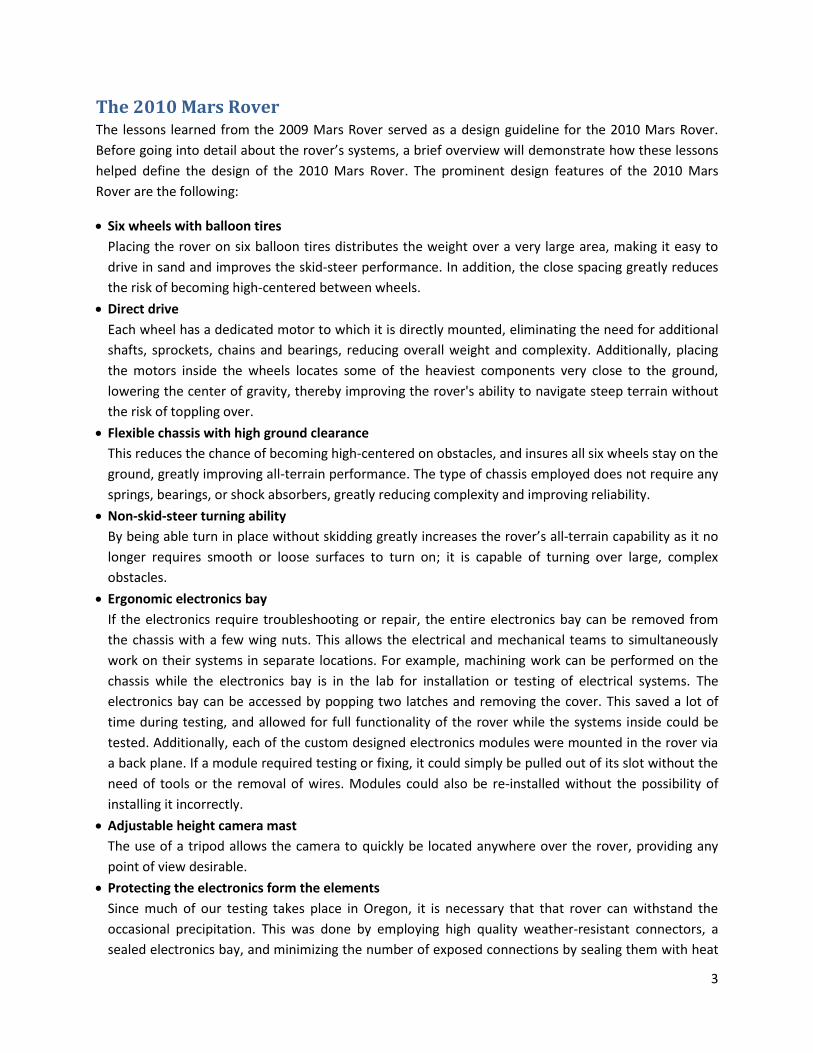
Wheels From the 2009 Rover it was learned that thin wheels, a heavy
chassis, and loose dirt make for poor skid-steering performance. The
wheels would dig themselves into the loose soil rather quickly
(Figure 3), which then required more torque than the drive train
could handle, resulting in skipping chains, and ultimately causing the
chain to fail.
The decision was made to spread the weight out over a larger area,
resulting in the choice of balloon tires (donated by WheelEEZ, Inc)
which exert little pressure on the ground and make skid-steering
very easy. The rim design of the WheelEEZ wheels is very convenient
for wheel assembly, making tire changes a quick and effortless
procedure.
Initially the motor did not fit into the rim, so some modification of
the rim was necessary to allow the motor to fit inside the wheel. The inner plastic cylinder of the rim
was machined away entirely, leaving only the inner rib structure. The motor interfaces with the wheel
Figure 3. 2009 Mars Rover's wheels easily sink into loose soil

6
by means of a 4-piece hub (Figure 4). This assembly fits inside one of the plastic rim halves which is then
mated to the other half of the rim with the tire in between. The whole assembly is held together by
means of a hub cap, with two screws that thread into the hub. When tightened, these screws pull the
two rim halves together while securing the hub inside the wheel.
In order to gain more traction on loose surfaces, the tires were upgraded with a polyurethane tread. The
strips that make up the tread were cut from stock sheets of polyurethane with a standard sheet-metal
break press, and bonded to the polyurethane tire using a cyanoacrylate adhesive (Krazy Glue).
Chassis
The chassis (Figure 5) was designed to keep all
six wheels on the ground over any terrain
without the use of heavy springs or shock
absorbers. The center frame has three pivot
points on it, two on either side of the front and
one on the back. Each of these pivot points has
a hinged set of two wheels attached to it, called
a "bogie". This insures that when driving over
uneven terrain, the center pivot of any given
bogie maintains the average deflection of the
wheel pair, keeping all wheels on the ground,
providing an overall smoother ride. The real
advantage to this design is that it eliminates the
need for any sort of heavy spring or shock
absorber suspension, allowing for a simpler and more light-weight design (less things to break). This
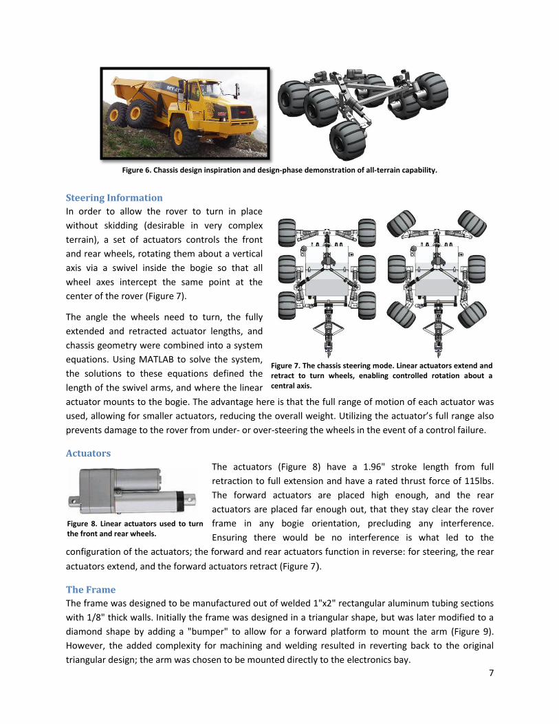
concept is not unique in itself, it can be seen on off-highway articulated trucks (Figure 6).
In the 2010 Mars Rover chassis design, the rear bogie is similar in function to the front of the truck. In
effect, the chassis is flipped 180 degrees. This was done to insure the front of the rover would
experience a smoother ride than the back, as this is where the arm will be mounted. This orientation
also eliminates the raised "tail" from the camera's forward field of view. A preview of the chassis' ability
to conform to terrain was generated during the design phase to provide insight into the all-terrain
performance of the chassis (Figure 6).
Figure 4. Wheel design and drive motor interface optimized for weight and quick tire changing. Balloon tires reduce ground pressure, enabling the rover to navigate loose soil without digging in. Tread was added to incease traction.
Figure 5. The chassis design, featuring a bogie-type suspension to passively conform to complex terrain, direct motor drive to each wheel, and linear actuator steering control.
7
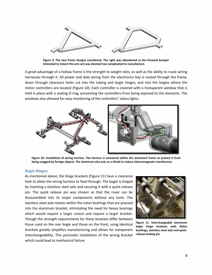
Steering Information
In order to allow the rover to turn in place
without skidding (desirable in very complex
terrain), a set of actuators controls the front
and rear wheels, rotating them about a vertical
axis via a swivel inside the bogie so that all
wheel axes intercept the same point at the
center of the rover (Figure 7).
The angle the wheels need to turn, the fully
extended and retracted actuator lengths, and
chassis geometry were combined into a system
equations. Using MATLAB to solve the system,
the solutions to these equations defined the
length of the swivel arms, and where the linear
actuator mounts to the bogie. The advantage here is that the full range of motion of each actuator was
used, allowing for smaller actuators, reducing the overall weight. Utilizing the actuator’s full range also
prevents damage to the rover from under- or over-steering the wheels in the event of a control failure.
Actuators
The actuators (Figure 8) have a 1.96" stroke length from full
retraction to full extension and have a rated thrust force of 115lbs.
The forward actuators are placed high enough, and the rear
actuators are placed far enough out, that they stay clear the rover
frame in any bogie orientation, precluding any interference.
Ensuring there would be no interference is what led to the
configuration of the actuators; the forward and rear actuators function in reverse: for steering, the rear
actuators extend, and the forward actuators retract (Figure 7).
The Frame
The frame was designed to be manufactured out of welded 1"x2" rectangular aluminum tubing sections
with 1/8" thick walls. Initially the frame was designed in a triangular shape, but was later modified to a
diamond shape by adding a "bumper" to allow for a forward platform to mount the arm (Figure 9).
However, the added complexity for machining and welding resulted in reverting back to the original
triangular design; the arm was chosen to be mounted directly to the electronics bay.
Figure 6. Chassis design inspiration and design-phase demonstration of all-terrain capability.
Figure 8. Linear actuators used to turn the front and rear wheels.
Figure 7. The chassis steering mode. Linear actuators extend and retract to turn wheels, enabling controlled rotation about a central axis.
8
A great advantage of a hollow frame is the strength to weight ratio, as well as the ability to route wiring
harnesses through it. All power and data wiring from the electronics bay is routed through the frame,
down through clearance holes cut into the tubing and bogie hinges, and into the bogies where the
motor controllers are located (Figure 10). Each controller is covered with a transparent window that is
held in place with a sealing O-ring, preventing the controllers from being exposed to the elements. The
windows also allowed for easy monitoring of the controllers’ status lights.
Bogie Hinges
As mentioned above, the hinge brackets (Figure 11) have a clearance
hole to allow the wiring harness to feed through. The bogie is hinged
by inserting a stainless steel axle and securing it with a quick-release
pin. The quick release pin was chosen so that the rover can be
disassembled into its major components without any tools. The
stainless steel axle rotates within the nylon bushings that are pressed
into the aluminum bracket, eliminating the need for heavy bearings
which would require a larger cutout and require a larger bracket.
Though the strength requirements for these brackets differ between
those used on the rear bogie and those on the front, using identical
brackets greatly simplifies manufacturing and allows for component
interchangeability. This precludes installation of the wrong bracket
which could lead to mechanical failure.
Figure 10. Installation of wiring harness. The harness is contained within the aluminum frame to protect it from being snagged by foreign objects. The aluminum also acts as a shield to reduce electromagnetic interference.
Figure 9. The two frame designs considered. The right was abandoned as the forward bumper (intended to mount the arm on) was deemed too complicated to manufacture.
Figure 11. Interchangeable aluminum bogie hinge brackets with Nylon bushings, stainless steel axle and quick-release locking pin

9
Chassis Stress Analysis
The bogie hinges are structurally critical parts as they are subjected
to significant loads when driving the rover into unexpected
obstacles. These loads are most severe on the rear hinge; if the
rover were to back into an obstacle with just one wheel, it will put a
significant load on the rear bogie hinge. When performing the stress
analysis, a worst-case scenario load of 110lbs (weight of rover) is
applied at the wheel in the direction of travel to determine if the
hinge is strong enough to absorb such an impact (Figure 12).
Assuming that the boundary conditions closely simulate the true
conditions, the stress in the hinge appears low enough (less than
125 MPa) to avoid a failure under this load (Figure 13). The base of
the frame was set as fixed and virtual screws were modeled to
clamp the bottom wall of the rectangular tube to the threaded
holes in the hinge. Non-intersect conditions are defined at all part
interfaces to account for contact stresses.
The first image in Figure 13 shows the surface stresses. Metal fatigue can occur at half of the yield stress
of a material provided tens of thousands of stress cycles occur in the same region. On this plot, a hot
spot appears in the weld joint under the "tail" of the frame. The second image shows that this is likely
the only area that will be prone to fatigue failures as all other volumes are subject to stresses below the
fatigue threshold. Since this is a worst-case scenario (and therefore rare), the risk of a fatigue failure is
very low.
If a critical stress concentration were identified however, one way to avoid such a hot spot is to modify
the surface to be co-planar with the iso-stress surfaces. In short, rounded corners are less likely to form
cracks. To reduce the likelihood of a fatigue failure in the above-described scenario, the location where
the analysis predicts a stress concentration was filed round to force it to spread out over a larger area.
This is a very effective and common technique to reduce stress concentrations.
Figure 13. Finite Element Analysis results for rear bogie hinge assembly. The location of maximum stress is expected to be on the inside weld; the magnitude is expected to be near the yield strength of 6061-T6 aluminum. This justifies heat treating the chassis to strengthen the annealed zones near the weld back to T6 temper.
Figure 12. Worst-case scenario load for rear bogie hinge assembly.

10
Robotic Arm
The arm is designed to be easily installed and
removed by a single person. To achieve this, it is
mounted to the rover using two slotted-pin hard
points (Figure 14). The arm was designed to work in a
square workspace of the dimensions outlined in the
competition rules. To reach every point in this
workspace, a Cartesian control system was used to
position the arm. The three major degrees of freedom
(left-right, up-down, forward-back) that control the
spatial position of the end-effector are driven by lead
screws and sleds. Turning a lead screw moves the arm
along a particular axis. The Z- and Y-axes of the arm
(up-down and left-right respectively) use the lead
screw directly to induce linear motion. The X-axis
(forward-back) on the other hand, uses an indirect
cam and slider to drive a scissor-arm extender. This results in a more compact configuration when the X-
axis is in the retracted position. On the end of the X-axis, two additional degrees of freedom where
added to control the orientation of the end-effector. Combined, these two joints are also called the
wrist. The wrist consists of a pitch and roll axis that allows the end-effector to be placed in the optimal
orientation for gripping or excavating.
For the two tasks in which the robotic arm is used, two separate and detachable end-effectors were
designed (Figure 15). The end-effectors attach to the wrist with a slot and pin connection. The end-
effector for the equipment servicing task consists of a gripper driven by a servo with an additional
adaptor for grasping the plug, flipping switches, and pushing buttons. A vibrator motor was mounted to
this end-effector to allow the arm to easily insert the plug into its receptacle; the vibrator motor greatly
reduced the pushing force required for this task, reducing the load on the arm. For the sample return
task, a duel bucket scoop was used with a detachable bag to store the collected samples in. The scoop
also features a high resolution point-and-shoot camera, used to take high-resolution pictures of the soil
sample before excavating it.
Figure 15. Two types of detachable end effectors: a gripper with vibrating motor to overcome the force required to insert the plug, and a double bucket scoop with sample bag, allowing operator to excavate large soil samples in multiple passes.
Figure 14. The removable robotic arm, featuring three linear axes and two axis end-effector.

11
The wiring harness for the arm is
routed directly from the electronics
bay to the microcontroller board
mounted above the Y-axis sled
(Figure 16). The main wiring harness
contains the power, data, and video
cables. From the microcontroller
board, the wiring harness splits into
three sub-harnesses. The first
follows up the Z-axis tower, the
second is routed along the Y-axis,
and the third travels out to the end-
effector. Each of the three linear
axis drive motors had its own motor
controller located with the motor
(Figure 36 in the Rover Electronics
section). The end-effector wiring
harness was routed through the
wrist roll axis to avoid pinching as
the end-effector turns. Each of the
different end-effector functions has its own plug, to allow for quick exchanging of end-effectors. To help
avoid over heating from the sun and to protect from the elements, each circuit board on the arm is
covered by an infrared reflecting Mylar sheath.
Arm Stress Analysis
The components that were scrutinized the most were the Y-axis guide rods and the X-axis cam. The two
guide rods that make up the structural support of the Y-axis were analyzed using simple beam theory to
calculate their deflection and stress. By themselves the two guide
rods preformed well with negligible deflection from the static weight
of the arm alone, but due to the large moment created when the X-
axis is extended, a secondary support bar was added. The X-axis cam
on the other hand was a point of high stress concentration. This
linkage is a point of pure bending as it has to supply the torque to
extend the X-axis of the arm. This was a concerning attribute, thus a
finite element analysis was performed to locate any potentially over-
stressed areas (Figure 17). Using a high grade 2014-T6 aluminum the
part would be well under-stressed.
Manufacturing the 2010 Mars Rover
Since the majority of the frame is welded, the manufacturing process for the chassis was quite involved.
Each frame section was cut to length and machined to the correct dimensions, then mounted in a jig
that allowed for quick and precise welding. For ease of machining and assembly, the entire fixture was
made of 1.25" thick high density particle board and assembled with glue. To save material, all fixture
Figure 17. Finite Element analysis of the X-axis cam. Based on this analysis, the chosen material for the cam was high strength 2014-T6 Aluminum
Figure 16. Overview of arm wiring harness. The arm's microcontroller was located at the base of the arm to reduce the number of cables needed to hook up to the electronics bay; only power and USB and two 75Ω BNC video connectors are used to interface with the rover.

12
components were cut from a single sheet of particle board using a CNC router (Figure 18, first image).
After being cut from the sheet, the rectangular pieces were glued into the base plate (second image)
and the rest of the cutouts were machined (third image). Machining after gluing the pieces in keeps any
misalignments accrued during gluing from affecting the final geometry of the fixture. The CNC router is
programmed to cut the slot features to the exact shape of the frame + 0.001" on either side for a fit
loose enough to slide the parts in. The horizontal pieces were then carefully glued into the slots to
provide a clamping surface to hold the aluminum frame pieces during welding. Once glued, the frame
pieces were inserted and welded (fourth image). A special fixture piece (visible on the right-hand corner
of the stock sheet) was made to weld the two tail pieces at the correct angle before being welded to the
rest of the frame as was specially requested by the welder.
Once welded, the 6061-T6 aluminum loses its heat treatment properties within an inch or so of any
welds and becomes much weaker. The entire chassis was put through a heat treatment process to bring
the tubing and welds back to a T6 temper. Only after this was completed, were the holes machined in
the frame as not to be affected by any warping during welding or heat treatment. A similar process was
followed to weld the individual parts of the bogies together.
In order to manage construction of the chassis, part numbers were assigned to each of the designed
parts in a way that would indicate which sub-assembly they belong in. This system allows for a coherent
block diagram with hierarchical structure
that makes it easy to see which parts belong
to a particular assembly (Figure 19). During
the manufacturing process, a part or
assembly was outlined in either a green
border (indicating the part was complete) or
a hatched yellow and black border
(indicating the part was not yet finished).
Parts that were not yet started were left
without an outline. By updating the borders
on the diagram (located on the team
website) daily, the team could track the
manufacturing progress. New parts could be
started by downloading the drawing file
(sorted by part number and located on the
same page) and beginning machining.
Figure 18. High density fiber board welding fixture for chassis frame. All pieces were CNC cut from a stock sheet of 1.25" thick sheet and glued together before CNC machining the slots used to hold the frame during welding.
Figure 19. Part number hierarchy with manufacturing status. This chart shows the assembly structure of the rover. It was updated regularly on the team design website during the manufacturing phase of the project to allow team members to track the production of the mechanical components on a day-to-day basis.
13
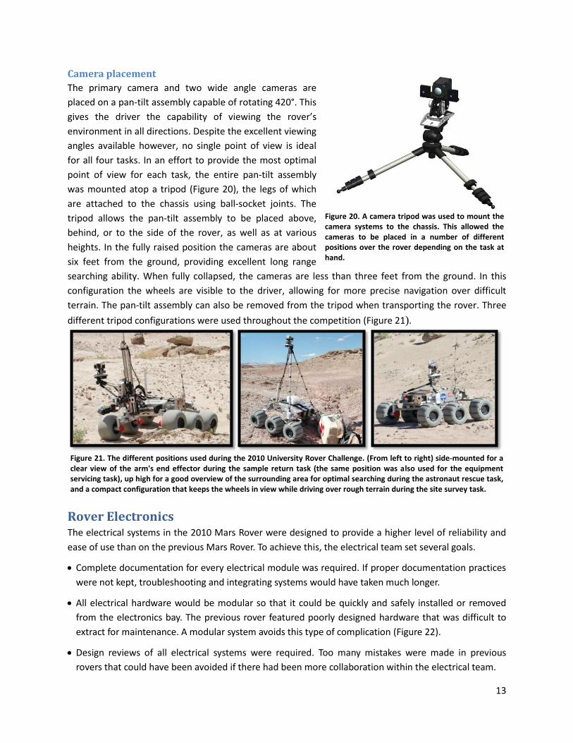
Camera placement
The primary camera and two wide angle cameras are
placed on a pan-tilt assembly capable of rotating 420°. This
gives the driver the capability of viewing the rover’s
environment in all directions. Despite the excellent viewing
angles available however, no single point of view is ideal
for all four tasks. In an effort to provide the most optimal
point of view for each task, the entire pan-tilt assembly
was mounted atop a tripod (Figure 20), the legs of which
are attached to the chassis using ball-socket joints. The
tripod allows the pan-tilt assembly to be placed above,
behind, or to the side of the rover, as well as at various
heights. In the fully raised position the cameras are about
six feet from the ground, providing excellent long range
searching ability. When fully collapsed, the cameras are less than three feet from the ground. In this
configuration the wheels are visible to the driver, allowing for more precise navigation over difficult
terrain. The pan-tilt assembly can also be removed from the tripod when transporting the rover. Three
different tripod configurations were used throughout the competition (Figure 21).
Rover Electronics The electrical systems in the 2010 Mars Rover were designed to provide a higher level of reliability and
ease of use than on the previous Mars Rover. To achieve this, the electrical team set several goals.
Complete documentation for every electrical module was required. If proper documentation practices
were not kept, troubleshooting and integrating systems would have taken much longer.
All electrical hardware would be modular so that it could be quickly and safely installed or removed
from the electronics bay. The previous rover featured poorly designed hardware that was difficult to
extract for maintenance. A modular system avoids this type of complication (Figure 22).
Design reviews of all electrical systems were required. Too many mistakes were made in previous
rovers that could have been avoided if there had been more collaboration within the electrical team.
Figure 21. The different positions used during the 2010 University Rover Challenge. (From left to right) side-mounted for a clear view of the arm's end effector during the sample return task (the same position was also used for the equipment servicing task), up high for a good overview of the surrounding area for optimal searching during the astronaut rescue task, and a compact configuration that keeps the wheels in view while driving over rough terrain during the site survey task.
Figure 20. A camera tripod was used to mount the camera systems to the chassis. This allowed the cameras to be placed in a number of different positions over the rover depending on the task at hand.
14
Excellent workmanship was required for all modules that would be installed in the 2010 Mars Rover. If
poorly built modules were implemented, they would likely fail and possibly destroy other electrical
systems.
The mechanical design would complement the electrical design. The spatial and thermal requirements
of all electrical systems were discussed with the mechanical design team. Doing this greatly improved
the functionality of the rover in areas where the two overlap.
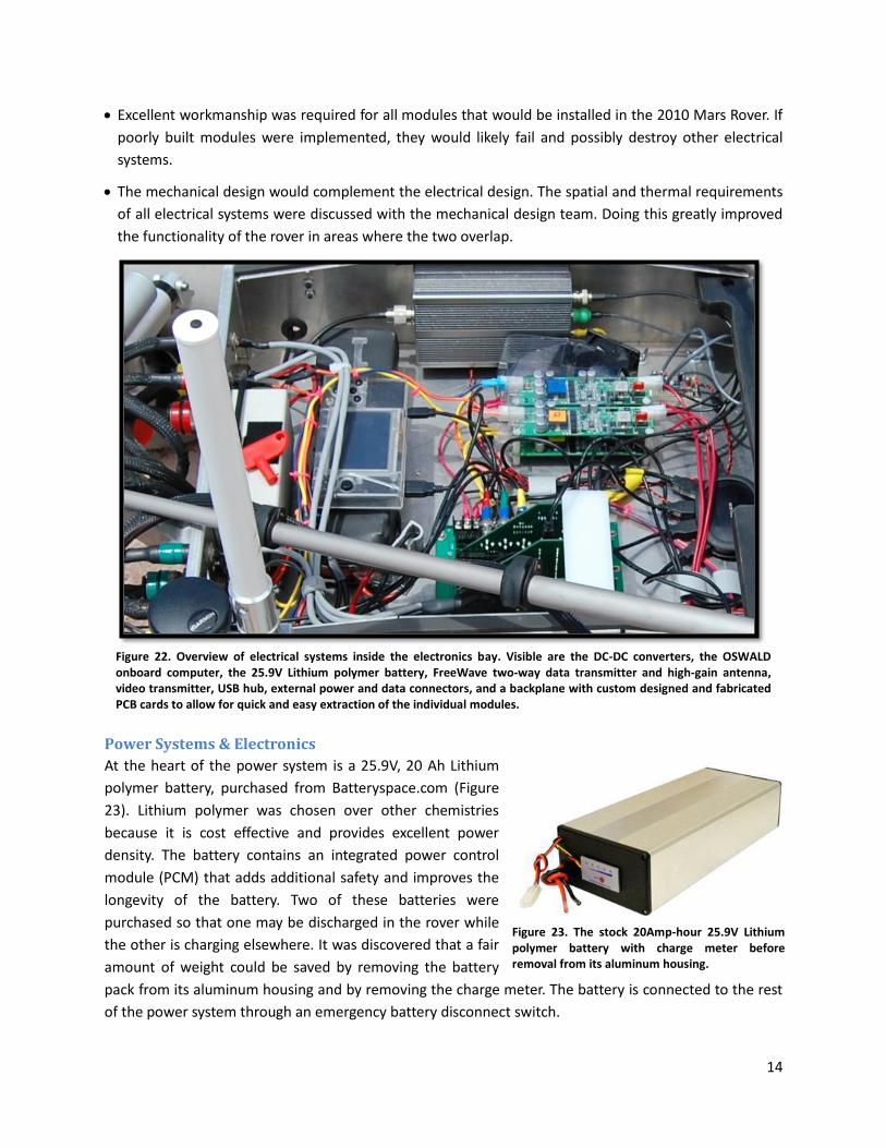
Power Systems & Electronics
At the heart of the power system is a 25.9V, 20 Ah Lithium
polymer battery, purchased from Batteryspace.com (Figure
23). Lithium polymer was chosen over other chemistries
because it is cost effective and provides excellent power
density. The battery contains an integrated power control
module (PCM) that adds additional safety and improves the
longevity of the battery. Two of these batteries were
purchased so that one may be discharged in the rover while
the other is charging elsewhere. It was discovered that a fair
amount of weight could be saved by removing the battery
pack from its aluminum housing and by removing the charge meter. The battery is connected to the rest
of the power system through an emergency battery disconnect switch.
Figure 22. Overview of electrical systems inside the electronics bay. Visible are the DC-DC converters, the OSWALD onboard computer, the 25.9V Lithium polymer battery, FreeWave two-way data transmitter and high-gain antenna, video transmitter, USB hub, external power and data connectors, and a backplane with custom designed and fabricated PCB cards to allow for quick and easy extraction of the individual modules.
Figure 23. The stock 20Amp-hour 25.9V Lithium polymer battery with charge meter before removal from its aluminum housing.
15
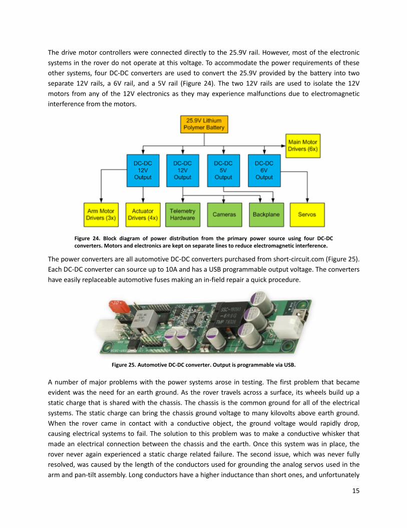
The drive motor controllers were connected directly to the 25.9V rail. However, most of the electronic
systems in the rover do not operate at this voltage. To accommodate the power requirements of these
other systems, four DC-DC converters are used to convert the 25.9V provided by the battery into two
separate 12V rails, a 6V rail, and a 5V rail (Figure 24). The two 12V rails are used to isolate the 12V
motors from any of the 12V electronics as they may experience malfunctions due to electromagnetic
interference from the motors.
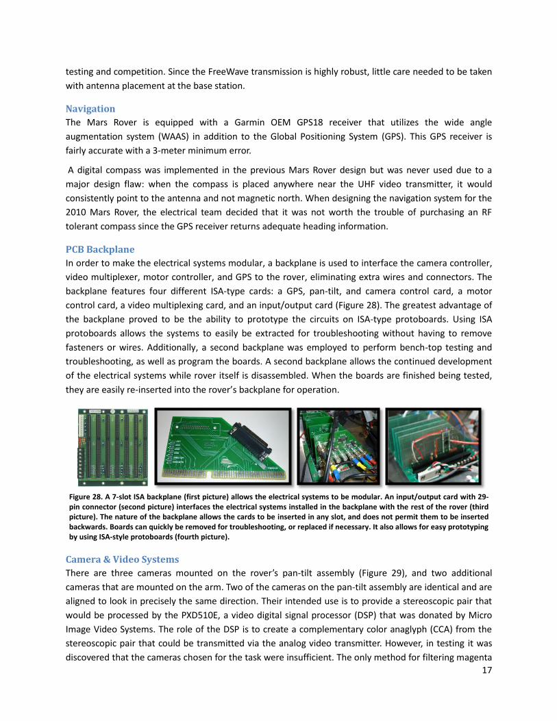
The power converters are all automotive DC-DC converters purchased from short-circuit.com (Figure 25).
Each DC-DC converter can source up to 10A and has a USB programmable output voltage. The converters
have easily replaceable automotive fuses making an in-field repair a quick procedure.
A number of major problems with the power systems arose in testing. The first problem that became
evident was the need for an earth ground. As the rover travels across a surface, its wheels build up a
static charge that is shared with the chassis. The chassis is the common ground for all of the electrical
systems. The static charge can bring the chassis ground voltage to many kilovolts above earth ground.
When the rover came in contact with a conductive object, the ground voltage would rapidly drop,
causing electrical systems to fail. The solution to this problem was to make a conductive whisker that
made an electrical connection between the chassis and the earth. Once this system was in place, the
rover never again experienced a static charge related failure. The second issue, which was never fully
resolved, was caused by the length of the conductors used for grounding the analog servos used in the
arm and pan-tilt assembly. Long conductors have a higher inductance than short ones, and unfortunately
Figure 25. Automotive DC-DC converter. Output is programmable via USB.
Figure 24. Block diagram of power distribution from the primary power source using four DC-DC converters. Motors and electronics are kept on separate lines to reduce electromagnetic interference.

16
they are necessary for delivering power to systems in remote areas of the rover such as the pan-tilt
assembly, and the arm servos. The analog servos are very sensitive to the noise produced by long ground
conductors; they twitch noticeably when the drive motors are operated at full power.
Radio Frequency Communications
Data and video are transmitted on separate
channels. Data is transmitted digitally over 2.4GHz
and video is transmitted as analog NTSC over
900MHz.
Analog video was chosen because of how simple
analog transmission is. No extra video encoding
hardware is necessary. Despite the simplicity, there
were still downfalls to this approach. Because of
this simplicity, the quality of the video signal is
largely dependent on line of sight between the
transmitting and receiving antennas. Subsequently,
a high antenna mast was employed to avoid
smaller obstacles including rocks and hills from
obstructing the line of sight; this explains why the
team erected a 25-foot-tall antenna mast at the
competition sites (Figure 27). To further increase signal strength, high gain antennas are used on the
rover and at the base station. The Mars Rover is equipped with a 900MHz, 5W video transmitter
connected to a 900MHz 9dBi collinear antenna mounted just above the top of the electronics bay (Figure
26). The collinear antenna has an omnidirectional response pattern that is ideal for transmitting reliably
from a moving platform.
The base station is equipped with a 900MHz video receiver
connected to a 900MHz, 12dBi Yagi antenna that is mounted
to the antenna mast with an antenna rotation system.
Rotating the Yagi antenna is essential because of its highly
directional response pattern. The RF transmission line from
the Yagi to the receiver is 100 feet long, so a very low loss
cable was necessary to maintain signal strength. The
receiver is connected to the Yagi with LMR400 coaxial cable.
Another issue with transmitting analog video over a single
channel is that it is not possible to transmit multiple video
signals simultaneously without multiplexing them and
subsequently reducing their frame rates by at least half.
Data is transmitted via two identical FreeWave wireless serial bridges. Each FreeWave is connected to a
2.4GHz, 5.5dBi collinear antenna. These data transceivers are capable of long range communication in
adverse conditions such as uneven terrain, allowing for stable control communications throughout
Figure 27. Erected base station antenna mast with 12dBi directional Yagi antenna on rotatable mount for receiving the analog video feed. Fully erected, the mast stands 25ft tall.
Figure 26. Placement of 900MHz and 2.4GHz collinear antennas for video and data transmission.
17
testing and competition. Since the FreeWave transmission is highly robust, little care needed to be taken
with antenna placement at the base station.
Navigation
The Mars Rover is equipped with a Garmin OEM GPS18 receiver that utilizes the wide angle
augmentation system (WAAS) in addition to the Global Positioning System (GPS). This GPS receiver is
fairly accurate with a 3-meter minimum error.
A digital compass was implemented in the previous Mars Rover design but was never used due to a
major design flaw: when the compass is placed anywhere near the UHF video transmitter, it would
consistently point to the antenna and not magnetic north. When designing the navigation system for the
2010 Mars Rover, the electrical team decided that it was not worth the trouble of purchasing an RF
tolerant compass since the GPS receiver returns adequate heading information.
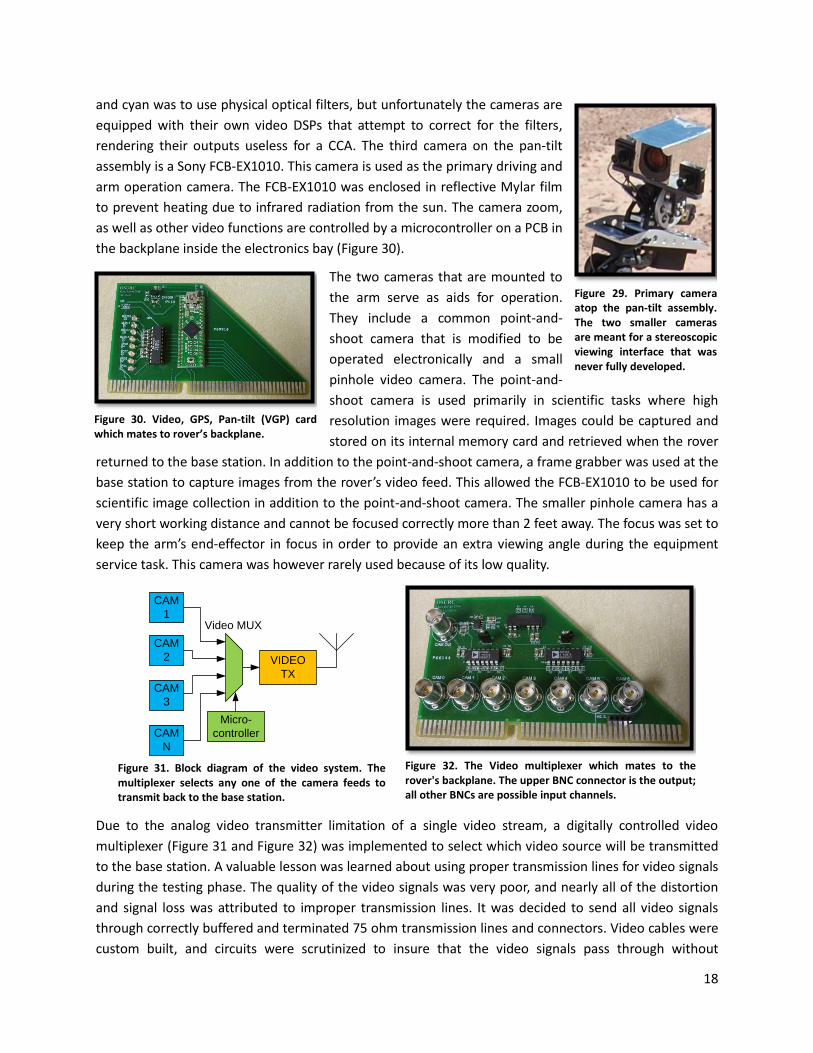
PCB Backplane
In order to make the electrical systems modular, a backplane is used to interface the camera controller,
video multiplexer, motor controller, and GPS to the rover, eliminating extra wires and connectors. The
backplane features four different ISA-type cards: a GPS, pan-tilt, and camera control card, a motor
control card, a video multiplexing card, and an input/output card (Figure 28). The greatest advantage of
the backplane proved to be the ability to prototype the circuits on ISA-type protoboards. Using ISA
protoboards allows the systems to easily be extracted for troubleshooting without having to remove
fasteners or wires. Additionally, a second backplane was employed to perform bench-top testing and
troubleshooting, as well as program the boards. A second backplane allows the continued development
of the electrical systems while rover itself is disassembled. When the boards are finished being tested,
they are easily re-inserted into the rover’s backplane for operation.
Camera & Video Systems
There are three cameras mounted on the rover’s pan-tilt assembly (Figure 29), and two additional
cameras that are mounted on the arm. Two of the cameras on the pan-tilt assembly are identical and are
aligned to look in precisely the same direction. Their intended use is to provide a stereoscopic pair that
would be processed by the PXD510E, a video digital signal processor (DSP) that was donated by Micro
Image Video Systems. The role of the DSP is to create a complementary color anaglyph (CCA) from the
stereoscopic pair that could be transmitted via the analog video transmitter. However, in testing it was
discovered that the cameras chosen for the task were insufficient. The only method for filtering magenta
Figure 28. A 7-slot ISA backplane (first picture) allows the electrical systems to be modular. An input/output card with 29-pin connector (second picture) interfaces the electrical systems installed in the backplane with the rest of the rover (third picture). The nature of the backplane allows the cards to be inserted in any slot, and does not permit them to be inserted backwards. Boards can quickly be removed for troubleshooting, or replaced if necessary. It also allows for easy prototyping by using ISA-style protoboards (fourth picture).
18
and cyan was to use physical optical filters, but unfortunately the cameras are
equipped with their own video DSPs that attempt to correct for the filters,
rendering their outputs useless for a CCA. The third camera on the pan-tilt
assembly is a Sony FCB-EX1010. This camera is used as the primary driving and
arm operation camera. The FCB-EX1010 was enclosed in reflective Mylar film
to prevent heating due to infrared radiation from the sun. The camera zoom,
as well as other video functions are controlled by a microcontroller on a PCB in
the backplane inside the electronics bay (Figure 30).
The two cameras that are mounted to
the arm serve as aids for operation.
They include a common point-and-
shoot camera that is modified to be
operated electronically and a small
pinhole video camera. The point-and-
shoot camera is used primarily in scientific tasks where high
resolution images were required. Images could be captured and
stored on its internal memory card and retrieved when the rover
returned to the base station. In addition to the point-and-shoot camera, a frame grabber was used at the
base station to capture images from the rover’s video feed. This allowed the FCB-EX1010 to be used for
scientific image collection in addition to the point-and-shoot camera. The smaller pinhole camera has a
very short working distance and cannot be focused correctly more than 2 feet away. The focus was set to
keep the arm’s end-effector in focus in order to provide an extra viewing angle during the equipment
service task. This camera was however rarely used because of its low quality.
Due to the analog video transmitter limitation of a single video stream, a digitally controlled video
multiplexer (Figure 31 and Figure 32) was implemented to select which video source will be transmitted
to the base station. A valuable lesson was learned about using proper transmission lines for video signals
during the testing phase. The quality of the video signals was very poor, and nearly all of the distortion
and signal loss was attributed to improper transmission lines. It was decided to send all video signals
through correctly buffered and terminated 75 ohm transmission lines and connectors. Video cables were
custom built, and circuits were scrutinized to insure that the video signals pass through without
Figure 32. The Video multiplexer which mates to the rover's backplane. The upper BNC connector is the output; all other BNCs are possible input channels.
VIDEO
TX
Micro-
controller
CAM
1
CAM
2
CAM
3
CAM
N
Video MUX
Figure 31. Block diagram of the video system. The multiplexer selects any one of the camera feeds to transmit back to the base station.
Figure 29. Primary camera atop the pan-tilt assembly. The two smaller cameras are meant for a stereoscopic viewing interface that was never fully developed.
Figure 30. Video, GPS, Pan-tilt (VGP) card which mates to rover’s backplane.
19
interference or loss. Because of the careful design of the video transmissions lines, the quality of the
video is excellent, and no video-related issues were encountered during the competition.
Motors & Motor Control Systems
The rover has six main drive motors, four motors that drive
the steering actuators, three motors that operate the arm’s
three axes, three servos in the arm’s wrist and two servos in
the pan-tilt assembly. Each motor system is different and
requires different control systems and hardware. Motor
control is handled by the motor control card, another
microcontroller on a PCB in the backplane (Figure 33).
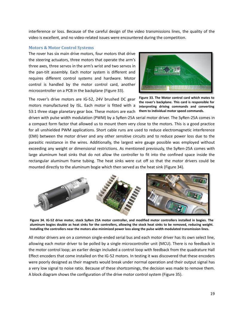
The rover’s drive motors are IG-52, 24V brushed DC gear
motors manufactured by ISL. Each motor is fitted with a
53:1 three stage planetary gear box. These motors are each
driven with pulse width modulation (PWM) by a SyRen-25A serial motor driver. The SyRen-25A comes in
a compact form factor that allowed us to mount them very close to the motors. This is a good practice
for all unshielded PWM applications. Short cable runs are used to reduce electromagnetic interference
(EMI) between the motor driver and any other sensitive circuits and to reduce power loss due to the
parasitic resistance in the wires. Additionally, the largest wire gauge possible was employed without
exceeding any weight or dimensional restrictions. As mentioned previously, the SyRen-25A comes with
large aluminum heat sinks that do not allow the controller to fit into the confined space inside the
rectangular aluminum frame tubing. The heat sinks were cut off so that the motor drivers could be
mounted directly to the aluminum bogie which then served as the heat sink (Figure 34).
All motor drivers are on a common single-ended serial bus and each motor driver has its own select line,
allowing each motor driver to be polled by a single microcontroller unit (MCU). There is no feedback in
the motor control loop; an earlier design included a control loop with feedback from the quadrature Hall
Effect encoders that come installed on the IG-52 motors. In testing it was discovered that these encoders
were poorly designed as their magnets would break under normal operation and their output signal has
a very low signal to noise ratio. Because of these shortcomings, the decision was made to remove them.
A block diagram shows the configuration of the drive motor control system (Figure 35).
Figure 34. IG-52 drive motor, stock SyRen 25A motor controller, and modified motor controllers installed in bogies. The aluminum bogies double as heat sinks for the controllers, allowing the stock heat sinks to be removed, reducing weight. Installing the controllers near the motors also minimized power loss along the pulse width modulated transmission lines.
Figure 33. The Motor control card which mates to the rover's backplane. This card is responsible for interpreting driving commands and converting them to individual motor speed commands.

20
The arm has three 12V brushed DC motors that are controlled by a custom developed motor driver. The
motor controller is designed to provide PWM based speed and direction control for small DC motors. A
microcontroller on the arm is responsible for generating the PWM signals to control all three motor
controllers. The arm microcontroller receives feedback for sled position from limit switches that are
located at the ends of each rail. These limit switches prevent the arm from moving the sled past the
hard-stop limit, avoiding any damage.
Servo Control
The pan-tilt assembly used to position the tripod-mounted cameras is
driven by two 6V analog servos. The servos are controlled by two PWM
signals generated by the VGP card (Figure 30). Unfortunately the analog
servos were not very precise, making pan-tilt control difficult when the
primary camera’s zoom was set to maximum. The arm was equipped with
three 6V analog servos. There are two servos used in the wrist and a third
operates the end-effector. These servos are controlled with PWM
generated by a microcontroller as well. During the 2010 competition it
became apparent that analog servos can be unreliable in harsh conditions
when the arm’s wrist roll servo ceased to function the day before the equipment servicing task. Without
a replacement available, the original control circuit was removed and replaced with an extra 12V motor
driver that was brought as a backup for an actuator or arm motor (Figure 36). A control loop was written
for the arm’s onboard microcontroller, restoring full functionality to the arm in time for the equipment
servicing task.
Figure 35. Block diagram of the rover's drive system. A single microcontroller sets the speed of each drive motor in the rover
Figure 36. Custom multipurpose motor controller. This controller is used in the arm as well as the linear actuators.

21
Linear Actuator Control
The four steering actuators each contain a 12V brushed DC motor and limit switches. In order to greatly
simplify the control of the actuators, the steering system is designed to only operate in two
configurations. Both configurations are achieved by moving the actuators to their fully retracted or
extended positions, intermediate position control was therefore not required. In the stock configuration,
the integrated limit switches are designed to disconnect the actuator motors when they reach their
mechanical limits. However, after a few cycles, the actuators began to malfunction intermittently, and
would resume normal operation after a few solid taps on the housing. These malfunctions were deemed
unacceptable; a solution to this problem was required.
After some investigation, the malfunctioning behavior was attributed to a poorly designed limit switch
circuit. The intended operation of the circuit is for the motor current to pass through the switches. The
switch is to be opened when the motor moves the actuator near its physical limit, disconnecting the
motor before the actuator damages itself. This switch is connected in parallel with a diode that, once the
switch is opened, will allow current to pass only in the direction, allowing the motor only to move the
actuator away from its mechanical limit. The flaw in the design is twofold. First, when the circuit is
opened, the rotational momentum of the motor continues to extend or retract the actuator, the amount
depending on the mechanical load applied. This load dependence makes the stroke length of the
actuator highly unreliable. Second, the limit switches disconnect the motor as current is passing through
the motor’s coil, reverse biasing the diode, causing a large voltage to generate across the switch
contacts. When the voltage is sufficient, an arc is formed and the switch contacts become corroded. If
the switch is then closed again, the corrosion prevents conduction between the contacts. The actuator
will behave normally until the opposite limit switch is engaged preventing current from passing in either
direction.
To solve this problem the actuators were modified such that the current to
the motors was no longer passed through the limit switches and diodes.
Instead, the limit switches were used as sensors and connected to a
modified version of the custom 12V motor that was installed inside the
actuator housing (Figure 37). The driver implemented combinational logic
to control the direction signal. The limit switched would tell the motor
driver when to cut power from the motor. Additionally, when the limit
switch was pressed, the driver would short the motor, preventing its
rotational momentum from extending or retracting the actuator any
further after shutoff. After this modification, the actuators behaved reliably
both electrically and mechanically and never malfunctioned again.
Rover Software All the rover’s software was written in C or C++ and runs on Linux. Standardizing on a compiler (GCC)
and an operating system simplified the design, helped eliminate incompatibilities, and allowed all the
software to run and be tested on a single computer. This configuration also allows code to be shared
easily between separate modules, such as the communication system for the rover and base station.
Figure 37. Custom-built motor controller mounted inside the linear actuator. The actuator’s limit switches act as sensors for the controller to turn off the actuator motor.

22
USB Communication
Each module of the rover communicated with a USB interface which connected to a 4 port hub. Using
USB allowed for quick firmware development, since each module could be tested independently on a
laptop computer, instead of waiting for the entire electrical and communication system to be built. The
firmware was developed using the LUFA (Light USB for AVR) library. LUFA is an easy-to-use, clean, simple
framework for building USB HID devices for AVR AT90USB and ATMEGA xxU microcontrollers.
Embedded Linux Controller
The rover is controlled with a small computer running Linux with an ARM-8 processor. The computer
used is an OSWALD (Oregon State Wireless Active Learning
Device), developed at OSU for use in undergraduate computer
science classes (Figure 38). It provides an LCD touch screen,
several USB ports, and independent power. Using a Linux
computer allows the rover software to be developed and
tested on a laptop, allowing for faster development.
Additionally, in the event of a hardware failure, the OSWALD
can be quickly replaced with any laptop computer running
Linux. The screen also provides feedback for what, if any,
commands are received by the rover.
Rover Software Design
The rover software uses a modular design, with a process manager. The process manager receives
command packets sent over the FreeWave radio, decodes them, and passes the messages off to the
separate modules. Each module is responsible for controlling a separate piece of hardware on the rover.
The modules used on the 2010 rover were:
Motor Control
Video/GPS/Pan-Tilt (VGP)
Arm Control
Wireless/Communication Module
Each module runs in a separate thread, and communicates with an associated USB HID device. The
process manager is responsible for system startup and passing messages between modules.
Data Communication Protocol
Data communication between the base station and rover is achieved through a simple packet-based
protocol. Each packet contains information on the source, the length, the target module, and finally,
binary data. The wireless module decodes the incoming packet, determines what the target module is,
and passes the message on to the process manager for delivery to the target module.
Because the serial communication provided by the FreeWave is stream-based (like TCP), many packets
may arrive at once. The received data is read into a buffer, and the wireless communication module
parses the buffer into packets. Each packet has a start and end byte (with byte stuffing) to ensure that
corrupted data dropped in transmission does not cause the entire system to fail (due to an invalid length
in the header, for example).
Figure 38. The Oregon State Wireless Active Learning Device (OSWALD). This small, light-weight device is the onboard computer.

23
Control Interface Design
The rover control interface in the base station runs on a Linux computer. It was written in C++, using the
Qt Toolkit. The data communication and message passing portions of the rover code are integrated into
and shared with the control interface. In order for the interface to be useful, it must provide the drive
team with meaningful information, and present it in a clean layout (Figure 39); a cluttered interface will
not be helpful for the drive team, as they will be unable to find necessary information quickly. The driver
interface has five major functions:
Displaying System Status (basic debugging information indicating if the different rover modules were
running, communicating with the hardware, etc)
Displaying GPS Coordinates and location on a satellite map, along with the path driven.
Selecting which cameras are available to the “change camera” function on the joystick
Assisting with the task
Sending commands to control rover hardware
Task Assistance
The interface provides several tools to assist with the competition tasks. For several tasks, it is useful to
place markers on the map at various locations. This marker-plotting ability was employed during the
astronaut search, the site and survey, and sample return tasks to mark locations of interest on the
satellite image. For the sample return task, the interface has the ability to record notes and save the
photos taken at a location on the map. The information recorded in the notes can be automatically
exported as a LaTeX documentation.
During the site survey task, the interface was used to assist in triangulation of markers. Two different
methods of generating the vectors needed for successful triangulation were employed during the task
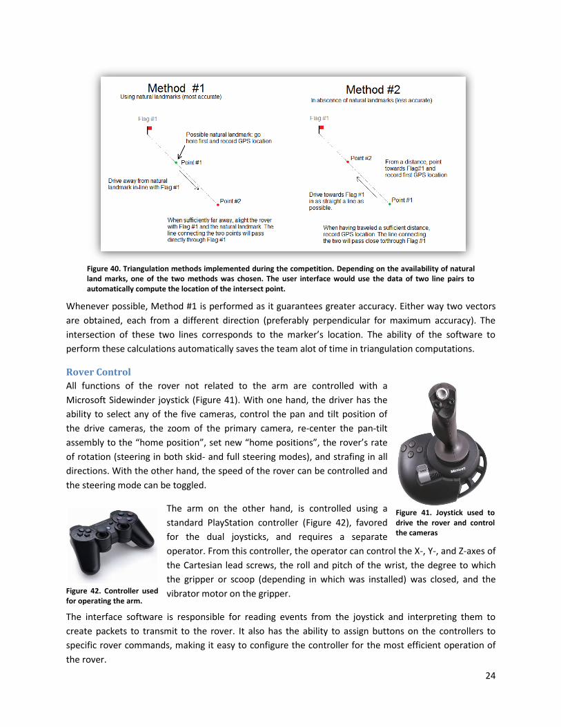
depending on the local topography and presence of distinctively identifiable features (Figure 40).
Figure 39. The driver interface. The interface includes navigational logs, ability to plot waypoints on a satellite photo, real-time GPS position information, camera check boxes to select which cameras can be cycled through, and a number of rover system status notifications.
24
Whenever possible, Method #1 is performed as it guarantees greater accuracy. Either way two vectors
are obtained, each from a different direction (preferably perpendicular for maximum accuracy). The
intersection of these two lines corresponds to the marker’s location. The ability of the software to
perform these calculations automatically saves the team alot of time in triangulation computations.
Rover Control
All functions of the rover not related to the arm are controlled with a
Microsoft Sidewinder joystick (Figure 41). With one hand, the driver has the
ability to select any of the five cameras, control the pan and tilt position of
the drive cameras, the zoom of the primary camera, re-center the pan-tilt
assembly to the “home position”, set new “home positions”, the rover’s rate
of rotation (steering in both skid- and full steering modes), and strafing in all
directions. With the other hand, the speed of the rover can be controlled and
the steering mode can be toggled.
The arm on the other hand, is controlled using a
standard PlayStation controller (Figure 42), favored
for the dual joysticks, and requires a separate
operator. From this controller, the operator can control the X-, Y-, and Z-axes of
the Cartesian lead screws, the roll and pitch of the wrist, the degree to which
the gripper or scoop (depending in which was installed) was closed, and the
vibrator motor on the gripper.
The interface software is responsible for reading events from the joystick and interpreting them to
create packets to transmit to the rover. It also has the ability to assign buttons on the controllers to
specific rover commands, making it easy to configure the controller for the most efficient operation of
the rover.
Figure 40. Triangulation methods implemented during the competition. Depending on the availability of natural land marks, one of the two methods was chosen. The user interface would use the data of two line pairs to automatically compute the location of the intersect point.
Figure 42. Controller used for operating the arm.
Figure 41. Joystick used to drive the rover and control the cameras

25
Science The primary background research for developing the science platform centered on established methods
in earth science, but ranged from remote sensing studies to studies of bench-top chemical analysis. In
order to locate and analyze a site with the potential to support extremophilic life, the team researched
the nature of various desert microbes and fungi, the process of biological crust formation, and methods
used to study desert soils both in the field and from remote surveyors.
The final platform draws heavily on the methods that Dr. Karnieli and his team used to find the spectral
profiles of cyanobacterial soils of the Sede Hallamish dune field along the border between Israel and
Egypt (Karnieli, 1999). Karnieli’s team used a portable reflectance spectrometer to study a variety of
samples in their dry state (one day after wetting with distilled water, and one week after wetting with
distilled water). Spectral reflectance plots contained many notable features, such as a local minimum
reflectance at roughly 670 nm (as is common of chlorophyll containing samples), lower overall
reflectance with increasing species richness in comparison to sand samples, and shifts in the onset of
the sharp slope increase near 700 nm. The study also showed a higher reflectance in the blue region
compared to sand for samples containing phycobilin pigments found in cyanobacteria.
The analysis of the returned sample was based on the methodology in this study. In order to select a site
for study, however, more detailed knowledge of crust communities and soil types was necessary. The
chief source sited for established methods and correlations in desert soil science was the U.S.
Department of the Interior Bureau of Land Management’s technical reference, Biological Soil Crusts:
Ecology and Management (donated by Oregon State University Crop and Soil Science professor, Dr. Jay
Stratton Noller).
Site Selection Parameters
The field results were obtained in a two part
procedure: assessment of macroscopic features
displayed on camera feed, and spectroscopic
analysis of the returned sample. Photos taken
from the correlative guidelines laid out in the
Department of the Interior technical reference
manual served as guidelines for site selection
(Figure 43). In coordination with these guidelines,
the team looked for sites that exhibited clear
microtopographical features and erosion
patterns, particularly the pinnacled surfaces
common to biological crusts in cool desert
regions such as the Colorado Plateau. These
features signify the soil’s ability to retain
moisture. Soil stability was noted in terms of the
quality of the rock cover, with stable or supportive soils containing partially submerged stones and few
loose surface pebbles (Figure 44). The color and texture of the soil were also examined as possible
Figure 43. Examples of criteria used to determine which soil features were deemed worth investigating.

26
indicators of the ability of the soil to absorb light and maintain the structural support necessary for
colonization by microbes and fungi.
Returned Sample Analysis
The returned sample was analyzed with a Vernier Scientific ALTA II Reflectance Spectrometer (Figure 45)
and compared to a negative control collected shortly before the task from an area of high disturbance.
Spectra were taken of samples dry and shortly after wetting with reverse-osmosis water, allowing for
the possibility of detecting spectral changes following the activation of dormant cyanobacteria. This
procedure simulated that used in Karnieli’s study and many others.
In order to learn how to optimize use of the instrument, the reflectance spectrometer was used to test
many objects and soil samples from various Corvallis locations before competition.
The ALTA II is an easily portable tool often used in educational settings. The
spectrometer contains a sample cell with a ring of eleven monochromatic
LEDs and a central light sensor. When the instrument is turned on, the
voltage on the display is recorded as the dark voltage, or baseline voltage.
Each LED is then activated separately by holding down the corresponding
button. Percent reflectance is then calculated from the comparative
differences between the sample and standard voltages obtained and the dark
voltage.
Sample voltage - Dark Voltage% Reflectance = × 100
Full Reflectance Standard Voltage - Dark Voltage
A photography 18% grey card was used as the calibration standard per the recommendation of the
manufacturer, and standard voltages were divided by 0.18 to project the voltage at full reflectance.
Samples were analyzed on black sample sheets to reduce backscattering, similar to the configuration of
the spectrometer used in the Karnieli study. The removable sheets were lined with plastic on the reverse
side to prevent leakage when the samples were wet. The spectrometer was operated under a fixed light
Figure 44. High resolution pictures returned by the rover from two of the sites investigated during competition. The first shows a number of partially submerged rocks, the second shows many loose rocks and lighter colors.
Figure 45. Reflectance spec-trometer used to investigate the presence of cyanobac-teria in the soil.

27
source to reduce inconsistency in readings due to changes in background lighting. The final results were
calculated from the average of three data points collected for each wavelength. Spectra were assessed
for local minima in the chlorophyll region, overall reflectance in relation to the baseline sample, and
graph behavior in the blue region.
Data Presentation and Documentation
The data was analyzed using a Microsoft Excel spreadsheet formatted with the formula for the
calculation of percent reflectance from the input of the calibration and sample voltages. The value of the
dark voltage was noted to be consistent within one volt over the instrument’s history of use and was
thus input as a constant. Plots were arranged to automatically update as the user input values,
streamlining data analysis time to meet the task requirements. The final presentation was given as a
slideshow (Figure 46).
Science References
1. Belnap, Jayne, Rosentreter, Roger, Leonard, Steve, Kaltenecker, Julie Hilty, Williams, John, and Eldridge, David. (2001). Biological Soil Crusts: Ecology and Management. Denver, Colorado: U.S. Department of the Interior Bureau of Land Management Printed Materials Distribution Center.
2. Karnieli, Arnon, Kidron, Giora J., Glaesser, Cornelia, and Ben-Dor, Eyal. (1999). “Spectral Characteristics of Cyanobacteria Soil Crust in Semiarid Environments”. Remote Sensing Environment, 69:67-65.
Figure 46. Example of a presentation slide for the sample return event. Comparison of spectra obtained from the task site to those obtained by Karnieli et al.

28
Conclusion The success of the 2010 Oregon State University Mars Rover is primarily due to keeping to a strict, but
realistic schedule and allotting time for testing, fixing, and improving operational reliability. A
multidisciplinary project such as this requires a lot of communication and discussion between the
various disciplines as each affects the other. Without proper communication, the various systems would
never have been so well integrated.
The schedule set forth by the team required the rover’s chassis to be built by the beginning of January
2010 and prototypes of the electrical systems and software to be completed by the end of the following
March. This provided a functional (but unproven) rover in time for a team trip in which the rover was
put through its paces in the outdoors (Figure 47, first picture). This left an additional three months for
testing and implementation of fixes and upgrades. The team managed to stay on this schedule very well,
largely due to the numerous public appearances scheduled, each of which required a presentable Mars
Rover in a driving state. However, a driving rover alone is not sufficient for the competition; it must be
reliable, and the drivers must know all of the rover’s capabilities and limitations so that it could be
operated at its limits efficiently without failing. Three months of testing and practice before the
competition was absolutely crucial to accomplishing this.
Simplicity is a crucial factor in creating a reliable design. A complex solution to a problem often has the
tendency to create more problems than it solves. A lot of care was taken to find elegant solutions to
problems (such as placing the motor controllers inside the bogies as described earlier in Motors & Motor
Control Systems on page 19). High quality electrical connections are also important, as improper wiring
and low quality connectors proved to be the most frequent cause of electrical failure. Addressing these
items greatly improved the rover’s operational reliability.
A great deal was learned in the process of designing and building the 2010 Mars Rover. The
interdisciplinary design experience each team member now has is very hard to come by, and will prove
invaluable to future engineering endeavors.
Figure 47. A successful design requires thorough planning in reliability, simplicity, user-friendliness, and ample time for testing and practice. Good team communication and a strict but realistic schedule made this possible.

29
Thanks to our sponsors
Impact 3D
Met-Tek Heat Treatment
Tim Noland Commercial Welding