the effect of wheel loading on a railway bridge: a case ... · the effect of wheel loading on a...
TRANSCRIPT

The Effect of Wheel Loading on a Railway Bridge: A Case Study on Minnamurra
Railway Bridge
PresentedDr. Olivia Mirza
Dr. MD Kamrul Hassan, Emile Assaf, Thy Pham and Guy StanshallWestern Sydney University

Overview of Presentation
FiniteElementModel
Conclusions
IntroductionResults
AndDiscussion

Introduction Finite Element Model Results and Discussion Conclusions
✓New South Wales, Australia alone has nearly 5000 bridges with 17%being older than 50 years old.
✓Over the last century, the transportation industry has increased theload for bridge structures which has caused a significant impact to thedesign life.
✓Not only loading, many studies have been conducted showing thatpoor detailing, imperfections, weld defects and holes can significantlyreduce the design life of the structure.
✓Australia’s maturing locomotives and railways concerns with faster andheavier loads will have negative effects to the railway infrastructure.
✓This will accelerate the deterioration of the railway system and increasethe chance of cracking from the sleepers and/or damage to the rail andfastening system failure.
Background

The aim of this project is to investigate the effect of wheel loading on the interaction between sleepers and railhead in the rail component system
for Minnamurra Bridge in Kiama NSW.
Minnamurra Bridge Section
Aims
Introduction Finite Element Model Results and Discussion Conclusions

Detail of Minnamurra Bridge
Railway LineConcrete Pier
ConcreteTransoms
Railway Line
Top view of box girder Section view of box girder with railway lineIntroduction Finite Element Model Results and Discussion Conclusions
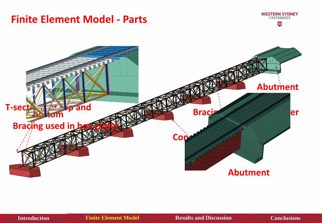
Finite Element Model - Parts
Concrete pier
Bracing used in box girder
Abutment
T-sections at top and bottom
Introduction Finite Element Model Results and Discussion Conclusions
Abutment
Bracing used in box girder
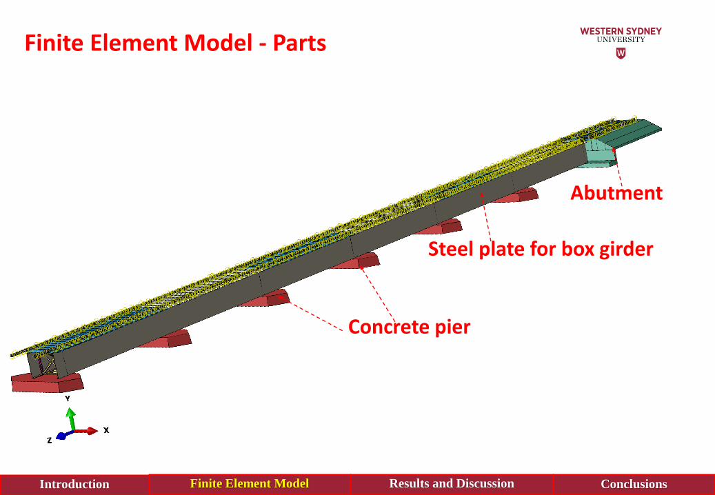
Concrete pier
Steel plate for box girder
Abutment
Introduction Finite Element Model Results and Discussion Conclusions
Finite Element Model - Parts

Finite Element Model – Contact and Interaction
Surface to Surface Contact
Introduction Finite Element Model Results and Discussion Conclusions
Sleepers and Steel Rail
Sleepers used tie contact
Sleepers used hard contact
Tie Constraints

Finite Element Model – Loading Condition
Introduction Finite Element Model Results and Discussion Conclusions
Railway traffic axle loads of 300LA (AS5100.2 Cl 8.2)

Finite Element Model – Loading Condition
Introduction Finite Element Model Results and Discussion Conclusions
Location of load cases considered for the FE analysis of Minnamurra Railway Bridge
Head of the Train = 360kN4 Wheel loading – Train Carriages

Finite Element Model – Boundary Condition
Introduction Finite Element Model Results and Discussion Conclusions
Minnamurra Railway Bridge

Finite Element Model – Material Properties
Introduction Finite Element Model Results and Discussion Conclusions
Str
ess
(N/m
m )
ys ps us
us
2
ys
Strain
Stress-Strain Relationship for Different Material Loh, et,.al (2003)
Material Rail Steel Steel Plates/Angles
E
(MPa)60, 000 200, 000
v 0.3 0.3
fy or fc’
(MPa)320 320
fu
(MPa)410 410

Finite Element Model – Material Properties
Introduction Finite Element Model Results and Discussion Conclusions
Concrete:
• Compressive strength, f’c = 40MPa
• Young’s Modulus of Concrete, Ec = 30, 000MPa
• Poisson ratio = 0.35
• Behaviour of concrete in compression is assumed to be linear up to 40% of the compressive strength (f’c)
Stre
ss, σ
(M
Pa)
Strain, ε
Stress-strain relationship of concrete, (Carreira & Chu 1985)

Behaviour of Railway Track
Introduction Finite Element Model Results and Discussion Conclusions
0
50
100
150
200
250
300
350
0 2 4 6 8 10
Stre
ss (
MP
a)
Time (STEP)
ABCDEFGH
0
50
100
150
200
250
300
350
0 2 4 6 8 10
Stre
ss (
MP
a)
Time (STEP)
B
C
D
E
F
G
050
100150200250300350
0 2 4 6 8 10
Stre
ss (
MP
a)
Time (STEP)
BCDEF
0
50
100
150
200
250
300
350
0 2 4 6 8 10
Stre
ss (
MP
a)
Time (STEP)
BCDEFG
First wheel of each load cases Second wheel of each load cases
Third wheel of each load cases Fourth wheel of each load cases
320
5010

Behaviour of Railway Track
Introduction Finite Element Model Results and Discussion Conclusions
Maximum stress
Stress distribution at Load Case A

Horizontal Sleeper Movement
Introduction Finite Element Model Results and Discussion Conclusions
Displacement Versus Time
0
0.1
0.2
0.3
0.4
0.5
0.6
0 2 4 6 8 10
Dis
pla
cem
en
t (m
m)
Time (STEP)
FIXED SLEEPERPINNED SLEEPER
0
2
4
6
8
10
12
14
16
0 2 4 6 8 10
Stre
ss (
MP
a)
Time (STEP)
FIXED SLEEPERPINNED SLEEPER
Stress Versus Time
Fixed Sleepers Pinned Sleepers

Rail and Sleeper Behaviour at Box Girder and Abutment
Introduction Finite Element Model Results and Discussion Conclusions
Location between Abutment and Box Girder
Box girder
Rail
Sleeper

Rail and Sleeper Behaviour at Box Girder and Abutment
Introduction Finite Element Model Results and Discussion Conclusions
Displacement distributions of rail and sleeper at the location of girder and abutment
(a) Rail at girder (b) Rail at abutment
(c) Sleeper at girder (d) Sleeper at abutment

From the project herein, it can be conclude that:
➢This project effectively studied the effects of wheel loading on theexisting railway components of the Minnamurra Railway Bridge, usingfinite element software ABAQUS where included the current wheel loadsaccording to the Australia Standard.
➢The critical component of the railway bridge was determined to be therail of the bridge as it experiences high levels of stress. The stress on therail is close to the yielding limit of the rail material.
Conclusions
Introduction Finite Element Model Results and Discussion Conclusions

➢The results showed a maximum stress of 320 MPa at the point of thewheel rail contact at each load location of the train and carriages.
➢The maximum vertical displacement across the railway bridge was 3mm.
➢It was found that the rail will no longer be adequate to supportincreasing loads of future trains.
Conclusions
Introduction Finite Element Model Results and Discussion Conclusions

➢Steel Rail require upgraded from 60kg to 68kg. This will ensure that therail can withstand faster and heavier locomotive and also to safeguardpassengers and assets into the future.
➢Improvement of the cross sectional shape of the rail head isrecommended where the width of the rail heads base, will reduce thelikeliness of buckling.
➢Due to the age of the Minnamurra Bridge, wear on the steel rail hasoccurred caused the rails undergo deformation that may cause wheelsslip off. Therefore, regular maintenance is recommended to maintain fullintegrity of the rail.
Recommendations
Introduction Finite Element Model Results and Discussion Conclusions

The authors would like to acknowledge the technicalsupport provided by Transport for New South Wales and
Western Sydney University for providing a conducive environment for this project

QU
ES
TI
ON
S