the creation of design modules for use in engineering
TRANSCRIPT
1Corresponding author 1 Copyright © 2012 by ASME
Proceedings of the ASME 2012 International Design Engineering Technical Conferences &
Computers and Information in Engineering Conference
IDETC/CIE 2012
August 12-15, 2012, Chicago, IL, USA
DETC2012-71181
THE CREATION OF DESIGN MODULES FOR USE IN ENGINEERING DESIGN EDUCATION
Garrett Foster Graduate Research Assistant
North Carolina State University Raleigh, North Carolina, USA
Micah Holland Graduate Research Assistant
North Carolina State University Raleigh, North Carolina, USA
Scott Ferguson1
Assistant Professor North Carolina State University Raleigh, North Carolina, USA
William Deluca Associate Professor
North Carolina State University Raleigh, North Carolina, USA
ABSTRACT Industry demands that graduating engineers possess the
ability to solve complex problems requiring multidisciplinary
approaches and systems-level thinking. Unfortunately, current
curricula often focus on analytical approaches to problem
solving. Further, adding courses focused solely on engineering
design is often unachievable due to the large amount of
material covered in today's undergraduate engineering
curricula. Combined, these prevent a comprehensive focus on
engineering design education from being realized. To
overcome these time and resource constraints, this paper
proposes the use of computational modules within current
courses. The investigators hypothesize that the modules would
eliminate the repetitive analysis barrier in design problems,
thus allowing for design-related experiences to be included
earlier in the curricula as opposed to postponing it to a
capstone experience. Four major hurdles that hinder successful
integration of modules in current engineering courses are:
a) engaging students such that they will want to use the
modules; b) ensuring the modules are easy to use; c) reducing
the complexity of deploying the modules into the classroom;
and d) providing educational value. To address these issues,
this paper treats the design of the modules as a product design
problem. This paper presents the redesign process followed to
improve two different design modules planned for
implementation in the engineering curriculum at North
Carolina State University. Additionally, this research indicates
that using a formal redesign process enhances a module’s
ability to overcome the hurdles listed above.
1. INTRODUCTION Recent events have demonstrated that our nation continues
to struggle to develop complex engineered systems. A prime
example is Boeing’s new 787 aircraft, which was delivered
more than three years late due to design and production
challenges [1] with a program cost exceeding $32 billion [2].
It is anticipated that such systems will only continue to become
more prevalent as the same technological advancements that
drive societal improvements lead to tightly coupled engineered
systems that exhibit complex component interactions [3]. This
has created a new generation of engineering challenges in the
areas of energy, environmental management, food and water,
housing, health, and transportation [4]. One approach to
combat the complexity in these systems is to divide the
problem into smaller segments such that more resources,
human or computational, can be used to work on the problem
in parallel. However, this leads to a new problem of how to
handle the interactions between the different segments [5,6].
Delegating this task to a single person is a poor strategy, as a
typical complex engineered system is too complicated and
possesses too much information [7]. Instead, utilizing a diverse
team of engineers that are skilled in multidisciplinary
approaches and systems-level thinking is a better strategy.
One way to develop this ability to solve complex,
multidisciplinary problems is to teach a variety of problem
solving techniques within the undergraduate curriculum [7,8].
These initial problem solving skills serve as the foundation for
learning how to develop complex engineered systems [9].
Dutson et al. [10] state that capabilities related to system
2 Copyright © 2012 by ASME
design, integration, and synthesis are what industry now
requires of graduating engineers. This view is enforced by a
National Science Board report [3], which claims "companies
want engineers with passion, some systems thinking, an ability
to innovate, an ability to work in multicultural environments,
an ability to understand the business context of engineering,
interdisciplinary skills, communication skills, leadership skills,
an ability to adapt to changing conditions, and an eagerness for
lifelong learning." Recent graduates are also discovering that
technical skills can more quickly become obsolete as markets
become more international. To maximize the competitiveness
of US engineering students, the National Science Board [3]
identifies that the context of engineering education must adapt
to ensure that students more directly meet today's industrial
needs.
Research in engineering education has shown that
improving a student's ability to solve complex,
multidisciplinary problems is accomplished by creating a
design thread, or design spine [11], where at least one design
course is featured each semester [12]. A Phase I report
designed to promote systematic innovation in engineering
education published by the American Society for Engineering
Education [13] states "...it is equally important that students
have design-related experiences early in their academic careers
and not wait for the senior design capstone experience to do
'real engineering'." This conclusion was reached after it was
shown that a one-way transition from theory-based courses to
an unstructured design project was not a particularly effective
way for students to learn. Instead, there should be a
"continuing back-and-forth" between theoretical principles and
design applications as students gain experience [14–16].
Unfortunately, adding courses focused on engineering
design education is often unachievable due to the large amount
of material covered in today's undergraduate engineering
curricula. Instead, this research begins to explore whether the
process of design can be integrated into the existing curricula
through the use of discipline specific computational design
software, which this paper refers to as “modules”.
Computational modules have the ability to overcome the time
and resource constraints that often make it difficult to
systematically evaluate and narrow down candidate solutions
in a classroom setting. From preliminary interviews with
faculty and students, and insights gained from literature, this
paper identifies four major hurdles that hinder successful
integration of modules in current engineering courses. These
hurdles are shown in List 1.
List 1. Implementation Hurdles
Engaging students such that they will want to use the
modules
Ensuring the modules are easy to use
Reducing the complexity of deploying the modules
Providing educational value
If these modules were a commercial product, it would be
fairly typical for them to go through a product design process
to improve their value to the customer. Therefore, the
objective of this paper is to extend the product design process
to the creation of computational modules used for engineering
education.
This section discussed the motivation for using a product
design process on two different modules for use in
undergraduate engineering curriculum at North Carolina State
University. In the next section, background material is
introduced. Section 3 discusses the process of redesigning the
two different Modules. Lessons learned from the redesign
process are presented in Section 4. Finally, closing remarks
conclude the paper in Section 5, along with a discussion of
future research.
2. RELATED WORK This research is focused on developing educational
engineering design software for undergraduate students. A
brief overview of both the use of computational tools in
engineering education and engineering design software is
discussed below.
2.1 Computational Tools in Engineering Education The use of computational tools has increased significantly
in engineering education over the last several decades. Today's
engineering student is expected to be proficient in different
computer languages, use generic software (spreadsheets, word
processors, presentation software) and, by their senior year, to
have gained experience in discipline-specific tools. While
computational competency, proficiency, and fluency are in
themselves building blocks of a future engineer's success,
computational tools also play a particularly important role in
engineering design, and the lack of adequate computational
tools produces a barrier to design in engineering education
primarily due to a "repetition barrier".
To address the need for computational tools in
engineering education, researchers have begun to explore
cyber-infrastructures that foster education and learning [17]. In
a design education context, Mund et al. [18] argue that the
incorporation of computational and design tools in modern
engineering courses is inevitable if we are to properly prepare
students for engineering practice. Computer-Aided Drafting
and Design (CADD) software and advanced analysis packages
allow students to analyze problems more quickly, and in a
greater level of detail, than using hand calculations. However,
a constant challenge is ensuring that students will adopt
software options made available to them. Philpot [19]
hypothesized, when developing MDSolids, that students will
adopt educational software if it helps them better understand
specific homework problems or immediate course concerns.
Software can then be designed to simulate highly specified
situations that represent learning objectives predefined by the
teacher [10]. However, such rigidity can hamper adoption and
dissemination. If flexibility is increased, software can solve
problems of specific interest to the student [18]. Such software
capabilities can foster problem solving skills that are not
inherent to traditional lectures or homework assignments [19].
By performing traditionally time-consuming analyses quickly,
design software allows students to focus on the more creative
aspects of design. Furthermore, the ability to solve complex
3 Copyright © 2012 by ASME
problems allows students to better appreciate the
multidisciplinary aspect of many engineering problems [18]
and realize the power of the analytical tools and concepts
earlier in the semester. Other benefits of using software to
improve design education include the ability for students to
arrive at the correct solution, fostering 'what-if' analyses,
ensuring solution repetition, and facilitating problem
visualization.
A review of engineering education research papers in the
Journal of Engineering Education and the International Journal
of Mechanical Engineering Education involving engineering
software yielded limited results. In papers that were found,
many improvements and implementations occurred at the
upper-end of the engineering curriculum [19–21]. Often,
discipline-specific software introduced at this stage of the
curriculum doubles as the software packages commonly used
in industry. Introducing software tools at the freshman and
sophomore levels can also be more challenging than later in
the curriculum. Research has shown that the impact of
computer software on the teaching of fundamental concepts in
mechanics of materials courses, for example, has been less
than successful [19]. Further, most software tools are rarely
multidisciplinary in nature.
2.2 Engineering Design Software To address the multidisciplinary and iterative nature of
engineering design problems, research within the engineering
design community has produced software tools with potential
applications in engineering education. These computational
tools overcome the time and effort limitations of repetition in
hand-performed calculations and drawings, called the
"repetition barrier", as well as other barriers associated with
collecting information and learning from experience. Design
repositories (DR), for example, have seen increased usage in
engineering design research and are a means of exchanging
general knowledge about a design [22] while constructing a
knowledge base to represent, archive, and search product
design information [23]. The knowledge‐centric basis of a DR
allows for the retrieval of design data that goes beyond charts
and tables, including the ability to search for components that
satisfy required functions, access to ideas of previous users,
visual representations of system behavior, and automated
concept generation [24–28]. In educational settings, DR
research has shown that students are motivated by the use of
repositories [29] and that students can spend more time on
cognitive tasks rather than spatial layout tasks [23]. One major
application of DRs in the classroom has been to facilitate
product dissection efforts [30], providing a common place for
groups to exchange knowledge and capture information for
future re‐use that would have otherwise been lost.
Noting that the design of large scale systems is commonly
conducted in a distributed design environment, research by
Gurnani and Lewis [31] developed a computer-based
infrastructure to facilitate communication and the passage of
information using Really Simple Syndication (RSS) feeds. The
intent of this work was to reduce the possibility of errors due
to inadequate information communication and handling among
the distributed subsystems. They proposed that errors could be
caused by "loss of design information emails, corruption of
attachments that include product data, duplication of files at
multiple locations, and different software being used to
complete the same design task." This work, however, has yet
to be fielded in an educational environment.
As an illustrative case study, the Applied Research
Laboratory Trade Space Visualizer (ATSV) supports
performance space exploration in conceptual design [32–34].
Software tools for multidimensional visualization are typically
designed to facilitate visual steering, often referred to as
“Design by Shopping” [35]. ATSV is designed to handle large
datasets from complex systems and allows a user to apply
constraints and preferences in a real-time environment. In
doing so, designers can simulate a large number of alternatives
and visualize them while forming preferences to aid the
selection of the best design. While "expert" users can leverage
the full ATSV toolset, recent research suggests that novice
users use multi-dimensional data visualization tools
ineffectively [36]. In fact, experimental testing showed the
quality of the design for novice users did not significantly
improve over random design/performance space sampling. The
inability for novice users to effectively use ATSV in a design
setting was attributed to users using only a subset of the tools
available - those they were comfortable with after limited
training [36]. In the implementation of DRs, research
demonstrated that user interfaces must be designed to
accommodate the student, students must be properly trained on
the software, and students must believe that use of the tool will
be worthwhile to their education experience [30]. Additionally,
traditional tutorial-based software promotes familiarity at the
expense of overall applicability. Worksheets and analysis
packages still require an initial investment in learning the
software, while outputting information in the form of tables
can be hard for students to visualize. This issue is significant,
as Mund et al. [18] propose that academic environments tend
to place a greater emphasis on the scientific aspects of the
model while commonly underestimating the difficulties
associated with developing accommodating user interfaces.
Even when using standard software packages, barriers can
exist in the classroom. In addition to the repetition barrier,
which is arguably the most significant barrier to design in early
engineering education, Ahlstrom and Christie [37] reported
that a majority of time was spent trying to teach students to use
and understand Matlab for the first time rather than
understanding and analyzing the problem - the original aim of
the exercise. Understanding how to use the software is only
possible after students understand the theory behind the
application. Therefore, adequately teaching theory before
introducing software applications is another barrier that
educators must overcome. Mund et al. [18] note that in "the
ideal case, a time lag of six to eight weeks (of teaching
analysis fundamentals) was observed to be necessary before
the software was introduced."
Finally, Feisel and Rosa [38] state that simulations can
lose value if they are too rigid, the models driving them are too
unrealistic, or if the simulated results do not match expected
real-world behavior. To overcome these barriers, Philpot [19]
suggests that software should be: a) easy to use, b) versatile in
4 Copyright © 2012 by ASME
the types of problems that can be solved, c) strongly visual,
and d) informative as to how or why calculations are used.
This section presented background on engineering design
software and the use of computational software in engineering
education. This paper will treat the design of two modules as a
product design problem. The process of developing,
implementing, and testing the modules is discussed in the next
section.
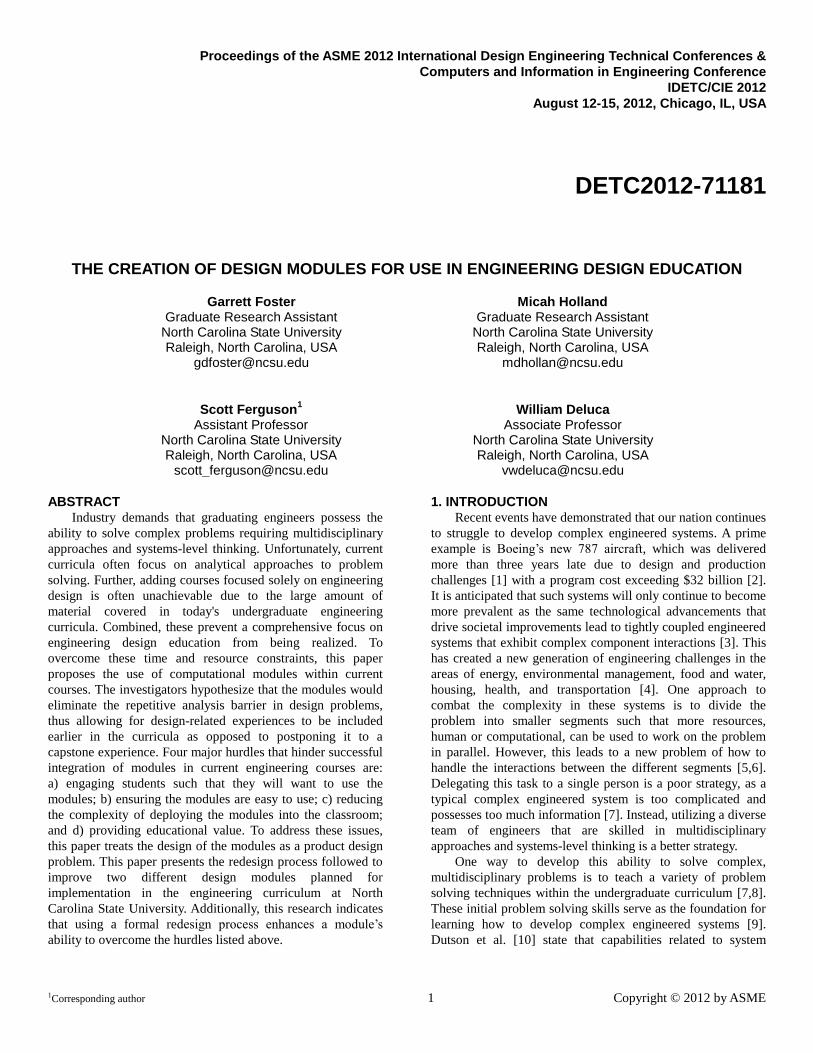
3. Product Design Process This section is broken into the four main activities
performed during the redesign of two modules. The two
modules used in this study were an airfoil design module and a
water rocket propulsion system design module. A general
flowchart of the process followed can be seen in Figure 1.
Subsection 3.1 discusses the process of acquiring
customer needs as well as insights from the activity. The
second subsection covers the thought process used to translate
the customer needs into engineering requirements and the
justification for introducing objectives into the process.
Subsection 3.3 discusses highlights from the concept
generation process in addition to describing some of the more
interesting ideas chosen for the final concepts. The final
subsection discusses the criteria chosen and the methodology
used to evaluate the prototypes against it. Together these
subsections encompass the early portion of the design phase
described in many popular design textbooks [39–41].
Figure 1. Product Design Process
3.1 Stakeholder Needs and Preference Identification The goal of this activity is to gain an understanding of
stakeholder needs or preferences. For this research, the term
‘stakeholder’ referred to both students and faculty, as they
were expected to have different perspectives and uses for the
product. To elicit their needs and preferences, one-on-one
interviews were performed with four engineering faculty and
six undergraduate engineering students ranging from
sophomore to senior level. Interviews were started by
explaining the motivation for incorporating modules into the
curricula. Initially interviewees were asked open ended
questions such as:
What are your perceptions of software use in the
classroom?
Can you walk me through the process of how you
used the software?
What might an assignment using software look like?
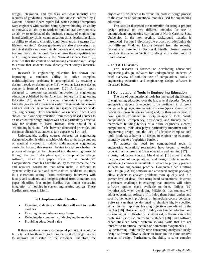
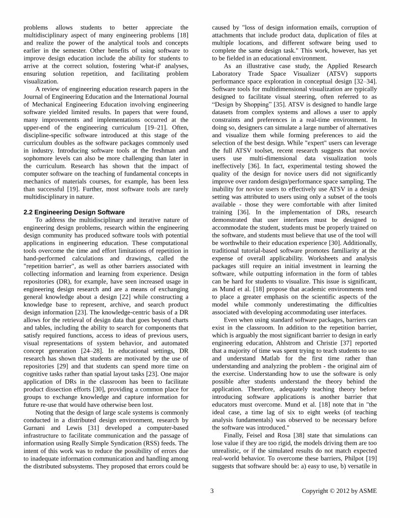
The second part of the interview consisted of allowing the
interviewees to interact with a first version of the modules
(Figures 2-3) while being asked what they liked, disliked, or
would have changed. A notebook was kept during the
interview process to quickly capture as much of the
information as possible. The following are some of the more
interesting observations that were recorded (Lists 2-4). For
organizational purposes, stakeholder needs and preferences are
broken down into three different areas: expected observations,
unexpected observations, and expected but unobserved
observations.
Figure 2. Original Airfoil Module
Figure 3. Original Propulsion Module
5 Copyright © 2012 by ASME
List 2. Expected and Observed Stakeholder
Preferences/Needs
Within the student group, there was apprehension
towards new software.
Within the student group, graphical user interfaces
were seen as “easier” than command line or text
editing.
Within the student group, there was a tendency to
click buttons at random.
Within the student group, there was a need to have
some initial guidance.
Within the student group, there was a need to limit
the number of pop-ups or distractions.
Within the faculty group, preference was given
towards using the modules outside of class.
Within both groups, there was a need to provide
adequate documentation.
Since this list consists of expected observations there were
not any major insights gained. However, it was interesting to
find that documentation or guidance came up in almost every
interview.
List 3. Unexpected and Observed Stakeholder
Preferences/Needs
Within the student group, there was a desire to have
multiple ways to input design information.
Within the student group, there was the desire to see
the old design information.
Within the student group, there was a need to
highlight the changes that happened.
Within the faculty group, there was a desire for
general purpose modules as opposed to problem
specific modules.
Within the faculty group, there was a desire for the
software to be usable without a graphical user
interface.
Within both groups, there was a desire for a
customizable or “universal” interface.
Within both groups, there was a desire to automate
part of the exploration process.
This list was full of surprises and opportunities to improve
the modules. The largest find was the preference for
customization within the interfaces. Interestingly this
preference was first discovered inadvertently when the
graphical editor of one of the modules was opened by mistake.
Further inspection of the list yields few items that likely should
have been expected, such as general purpose modules and the
ability to see previously evaluated design information.
List 4. Expected and Unobserved Stakeholder
Preferences/Needs
The module does not return incorrect data.
The module does not break or crash.
The level of fidelity within the module is satisfactory.
The module provides you with guidance to reach an
optimum.
Assessment occurs during or after module use.
The time required to calculate results is minimal.
No requirement to purchase additional software.
Within this final list, the majority of the preferences/needs
were likely not stated due to assumptions made by the
interviewee. For instance, it is not normal for software to
purposely return incorrect data. However, it was surprising that
not having to purchase additional software wasn’t mentioned.
A likely explanation of this non-observation is that engineering
students at North Carolina State University are able to freely
download most engineering software, such as Matlab [42], and
therefore are not concerned with the price of “free” software. It
is important to note that there was some mention of limiting
the hassle of downloading extra software.
3.2 Requirement Creation & Prioritization This subsection discusses: 1) the thought process used
during the creation of a requirements list from the stakeholder
preferences/needs identified in the previous subsection, and 2)
the inclusion of objectives into the process. A requirements list
is used to help guide the evaluation of the generated concepts
generated in Subsection 3.3. An initial requirements list for the
modules is shown in List 5.
List 5. Requirements
Allows user input
Displays design information
Displays performance information
Has documentation
Information returned is correct
Does not crash
Module calculates results in less than 15 seconds
Student is able to get first result in less than 5 minutes
Faculty can use the module in more than 1
assignment
Functional outside of classroom (does not require
specialized software)
Testing the initial requirements list on the original version
of both modules led to the discovery that alone, the
requirements provided very low fidelity in differentiating
which modules could best overcome the four hurdles in List 1.
Instead the requirements acted more as necessary conditions.
To overcome this limitation, objectives were created to
supplement the existing requirements. The supplemental
objectives list is shown in List 6. To better illustrate how the
usage of objectives improves the concept evaluation process
6 Copyright © 2012 by ASME
consider the following example. There are two modules being
considered, module A which has text input and module B
which has both text and slider input. Using only the
requirements, both modules would be considered equivalent
when evaluated versus the “allows user input” requirement.
However, when evaluated under the “maximize number of
ways to interact” objective, module B is superior. Further,
including arbitrary values in the requirements does little to
increase their utility. Again, consider module A and module B
from before. If the requirement was changed to “allows user at
least 2 ways to interact”, module B would be considered to
pass, while module A would fail. However, if module C was
introduced with three input types, it would also pass and be
considered equivalent to module B. However from an
objective standpoint module C would be superior to both
modules A & B.
List 6. Supplemental Objectives
Tier 1
o Minimize time to notice effect of input
o Minimize number of tries to get results
Tier 2
o Minimize time to give guidance
o Minimize time to get started
o Maximize amount of information quickly
available
o Maximize number of ways to interact
Tier 3
o Minimize number of user input errors
o Minimize number of unused parameters that are
visible
o Maximize number of parameter combinations
that can be visualized
o Maximize quantity of useful visual information
o Minimize number of unlabeled items
o Minimize time to get solution
o Maximize size of useful visual information
o Minimize number of clicks
Tier 4
o Minimize time to re-design/embodiment (the
step after the software)
o Maximize design space searched
o Minimize size of overlap of visual information
To further improve the ability of the objective list to direct
concept selection, the list was prioritized. The ability of each
objective to overcome the four hurdles was the basis of the
prioritization. For instance, will minimizing the overlap of
visual information increase engagement? Further, will it
increase the ease of use? In total four tiers were created. The
top tier was viewed as objectives that impacted all four
hurdles. The bottom tier contained objectives that only
impacted a single hurdle. Once the list was prioritized, only
the top two tiers of objectives were prioritized. This was to
decrease the redesign time so that the interviewees would still
be engaged in the project during the assessment phase.
3.3 Concept Generation & Selection This subsection describes the concept generation and
selection process. It also highlights some of the more
interesting feature ideas that were included in the prototype
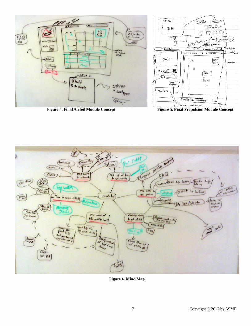
modules. During the brainstorming phase, a mind map was
created using the top two tiers of objectives from Subsection
3.2 as the main branches. The authors found many sources of
innovation from this specific form of brainstorming. This can
be attributed to the ease of representing certain ideas
associated with software design with text as opposed to
drawing them.
Using the ideas generated during the brainstorming phase
a series of concepts were created and evaluated based on their
ability to meet the requirements (List 5), satisfy the top two
tiers of objectives (List 6), and be easily implemented.
Motivation for ease of implementation is reducing the redesign
time such that participant engagement remains high. The
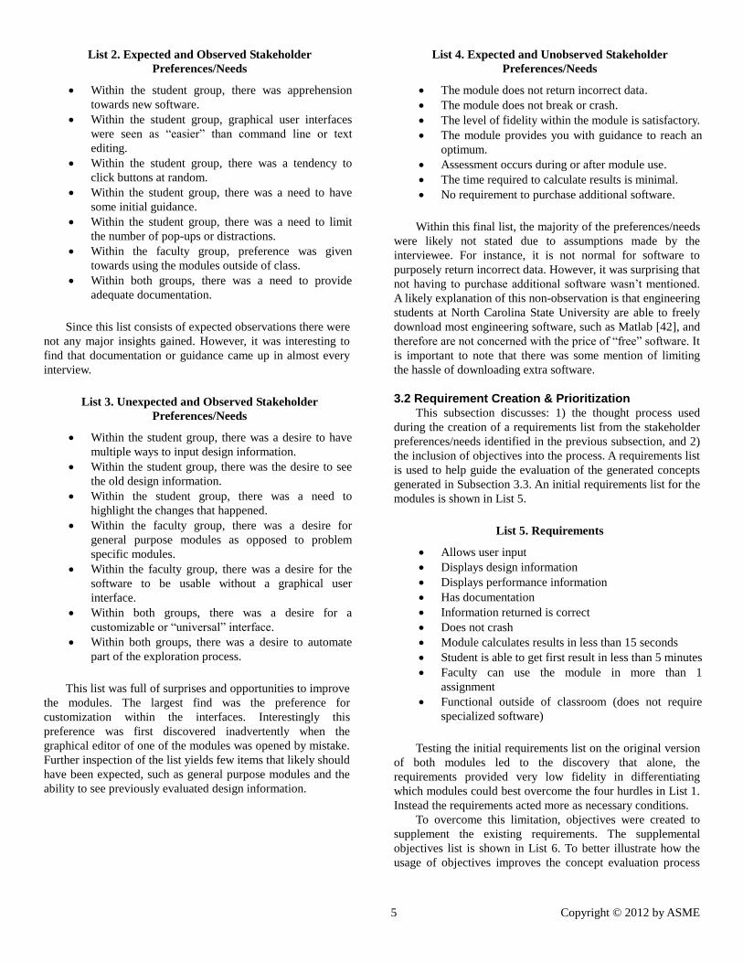
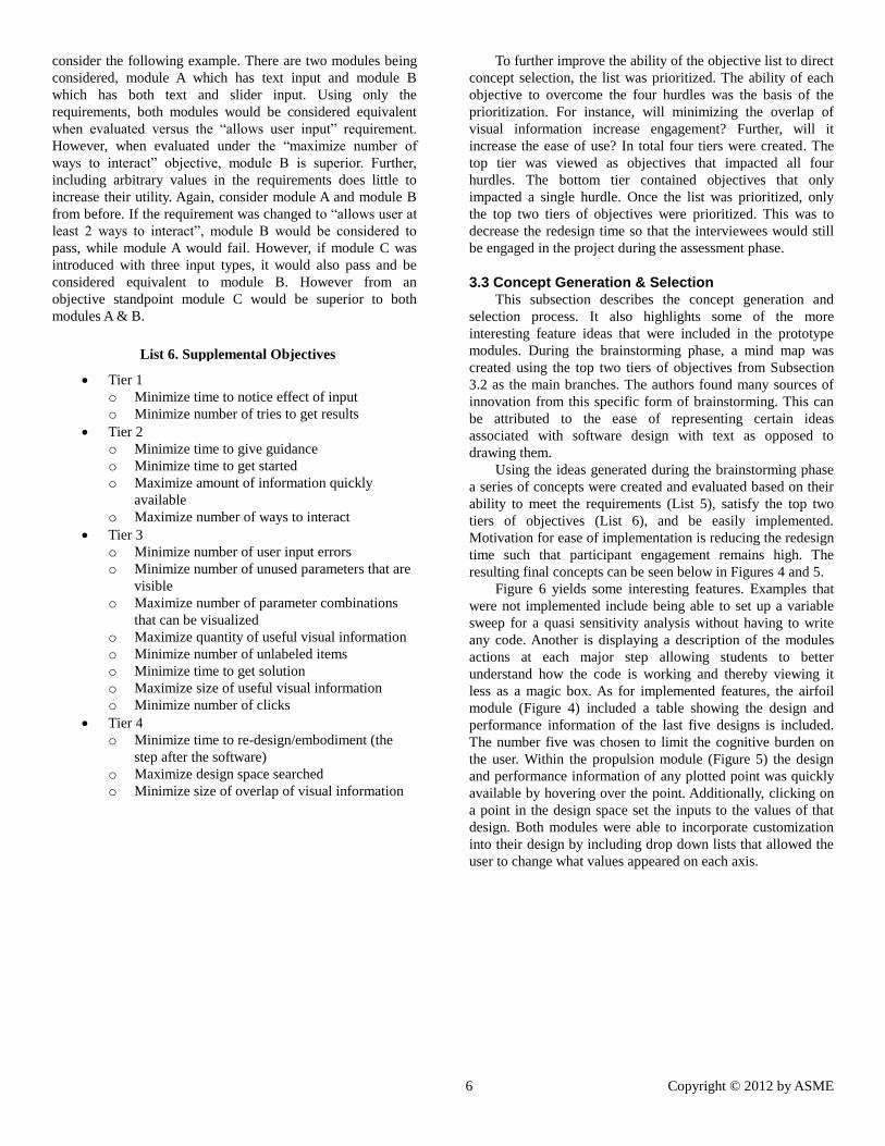
resulting final concepts can be seen below in Figures 4 and 5.
Figure 6 yields some interesting features. Examples that
were not implemented include being able to set up a variable
sweep for a quasi sensitivity analysis without having to write
any code. Another is displaying a description of the modules
actions at each major step allowing students to better
understand how the code is working and thereby viewing it
less as a magic box. As for implemented features, the airfoil
module (Figure 4) included a table showing the design and
performance information of the last five designs is included.
The number five was chosen to limit the cognitive burden on
the user. Within the propulsion module (Figure 5) the design
and performance information of any plotted point was quickly
available by hovering over the point. Additionally, clicking on
a point in the design space set the inputs to the values of that
design. Both modules were able to incorporate customization
into their design by including drop down lists that allowed the
user to change what values appeared on each axis.
7 Copyright © 2012 by ASME
Figure 4. Final Airfoil Module Concept Figure 5. Final Propulsion Module Concept
Figure 6. Mind Map
8 Copyright © 2012 by ASME
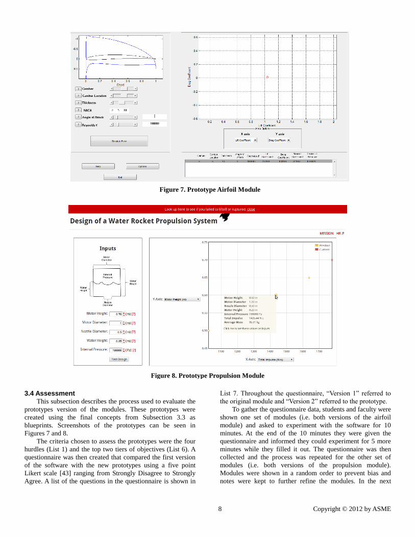
Figure 7. Prototype Airfoil Module
Figure 8. Prototype Propulsion Module
3.4 Assessment This subsection describes the process used to evaluate the
prototypes version of the modules. These prototypes were
created using the final concepts from Subsection 3.3 as
blueprints. Screenshots of the prototypes can be seen in
Figures 7 and 8.
The criteria chosen to assess the prototypes were the four
hurdles (List 1) and the top two tiers of objectives (List 6). A
questionnaire was then created that compared the first version
of the software with the new prototypes using a five point
Likert scale [43] ranging from Strongly Disagree to Strongly
Agree. A list of the questions in the questionnaire is shown in
List 7. Throughout the questionnaire, “Version 1” referred to
the original module and “Version 2” referred to the prototype.
To gather the questionnaire data, students and faculty were
shown one set of modules (i.e. both versions of the airfoil
module) and asked to experiment with the software for 10
minutes. At the end of the 10 minutes they were given the
questionnaire and informed they could experiment for 5 more
minutes while they filled it out. The questionnaire was then
collected and the process was repeated for the other set of
modules (i.e. both versions of the propulsion module).
Modules were shown in a random order to prevent bias and
notes were kept to further refine the modules. In the next
9 Copyright © 2012 by ASME
section the results from these surveys as well as other lessons
learned will be presented and discussed.
List 7. Sample Questionnaire
1. Version 2 is more engaging than Version 1.
2. Version 2 is easier to use than Version 1.
3. Classroom deployment is easier with Version 2 than
Version 1.
4. Version 2 increases the understanding of the material
more than Version 1.
5. Reactions are observed quicker in Version 2 than
Version 1.
6. Version 2 requires fewer attempts to gets results than
Version 1.
7. Guidance is received quicker with Version 2 than
Version 1.
8. The time to get started is shorter with Version 2 than
Version 1.
9. Version 2 has more information quickly available
than Version 1.
10. There are more ways to interact with Version 2 than
Version 1.
4. LESSONS LEARNED
In this section the results from two questionnaires, one for
the airfoil module and one for the propulsion module, are
discussed. Again, the respondents were asked a series of ten
comparative questions (List 7) with responses ranging from 1
(strongly disagree) to 5 (strongly agree). The 12 respondents
included students and faculty. The students ranged from
sophomore level to graduate level and all were pursuing
engineering degrees. The results of the ten questions are
provided and discussed in the three subsections below.
4.1 Hurdle Analysis
In Section 1, four hurdles were identified (List 1) that
hindered the successful integration of modules into existing
engineering courses. In this subsection, the ability of the
redesign process to address these four hurdles is discussed.
Figures 9-12 show an overview of the responses to questions
1-4 from the questionnaires (List 7) that specifically address
these hurdles. Table 1 shows the confidence intervals
corresponding to the same group of data. A quick inspection of
the figures indicates that both modules showed improvement
from the redesign process. Also, the airfoil module showed
greater improvement than the propulsion module. However, it
is important to note that these results do not to say that the
airfoil module is better equipped to overcome the four hurdles
than the propulsion module.
Looking at the confidence intervals in Table 1, we see that
the product design process was able to improve the abilities of
both modules to overcome all four hurdles. This finding is
very encouraging, especially since improvements were seen
across all criteria for two independent modules.
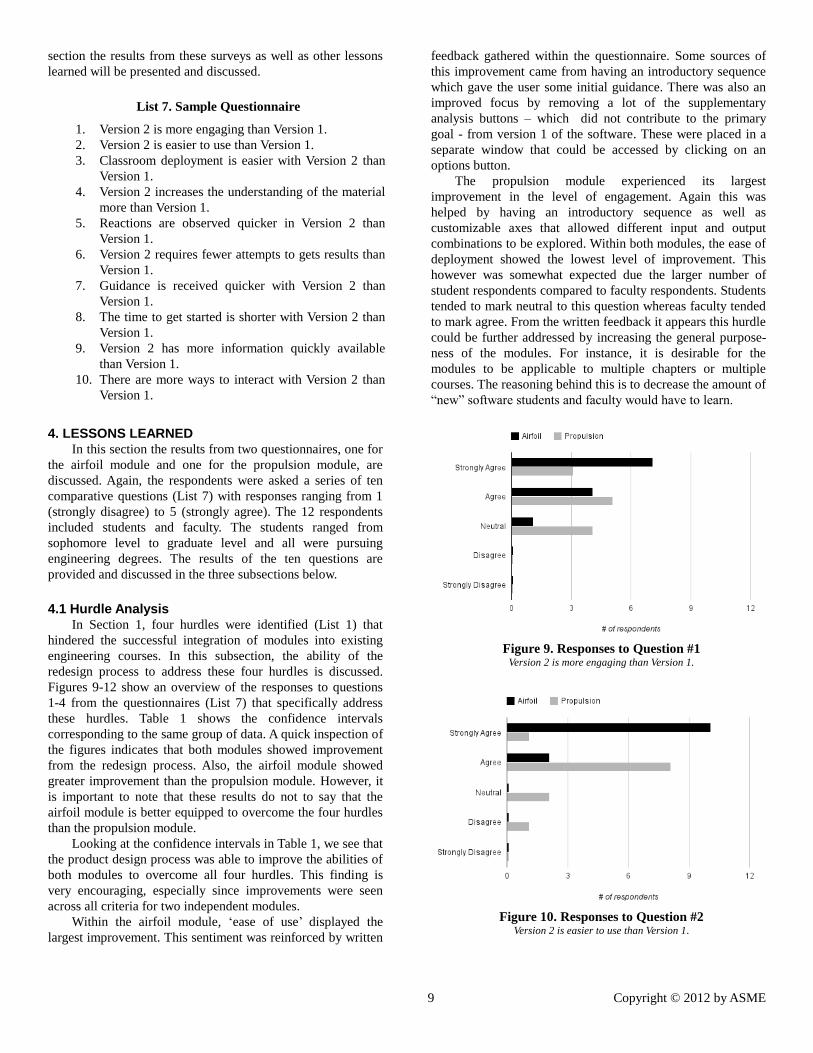
Within the airfoil module, ‘ease of use’ displayed the
largest improvement. This sentiment was reinforced by written
feedback gathered within the questionnaire. Some sources of
this improvement came from having an introductory sequence
which gave the user some initial guidance. There was also an
improved focus by removing a lot of the supplementary
analysis buttons – which did not contribute to the primary
goal - from version 1 of the software. These were placed in a
separate window that could be accessed by clicking on an
options button.
The propulsion module experienced its largest
improvement in the level of engagement. Again this was
helped by having an introductory sequence as well as
customizable axes that allowed different input and output
combinations to be explored. Within both modules, the ease of
deployment showed the lowest level of improvement. This
however was somewhat expected due the larger number of
student respondents compared to faculty respondents. Students
tended to mark neutral to this question whereas faculty tended
to mark agree. From the written feedback it appears this hurdle
could be further addressed by increasing the general purpose-
ness of the modules. For instance, it is desirable for the
modules to be applicable to multiple chapters or multiple
courses. The reasoning behind this is to decrease the amount of
“new” software students and faculty would have to learn.
Figure 9. Responses to Question #1 Version 2 is more engaging than Version 1.
Figure 10. Responses to Question #2 Version 2 is easier to use than Version 1.
10 Copyright © 2012 by ASME
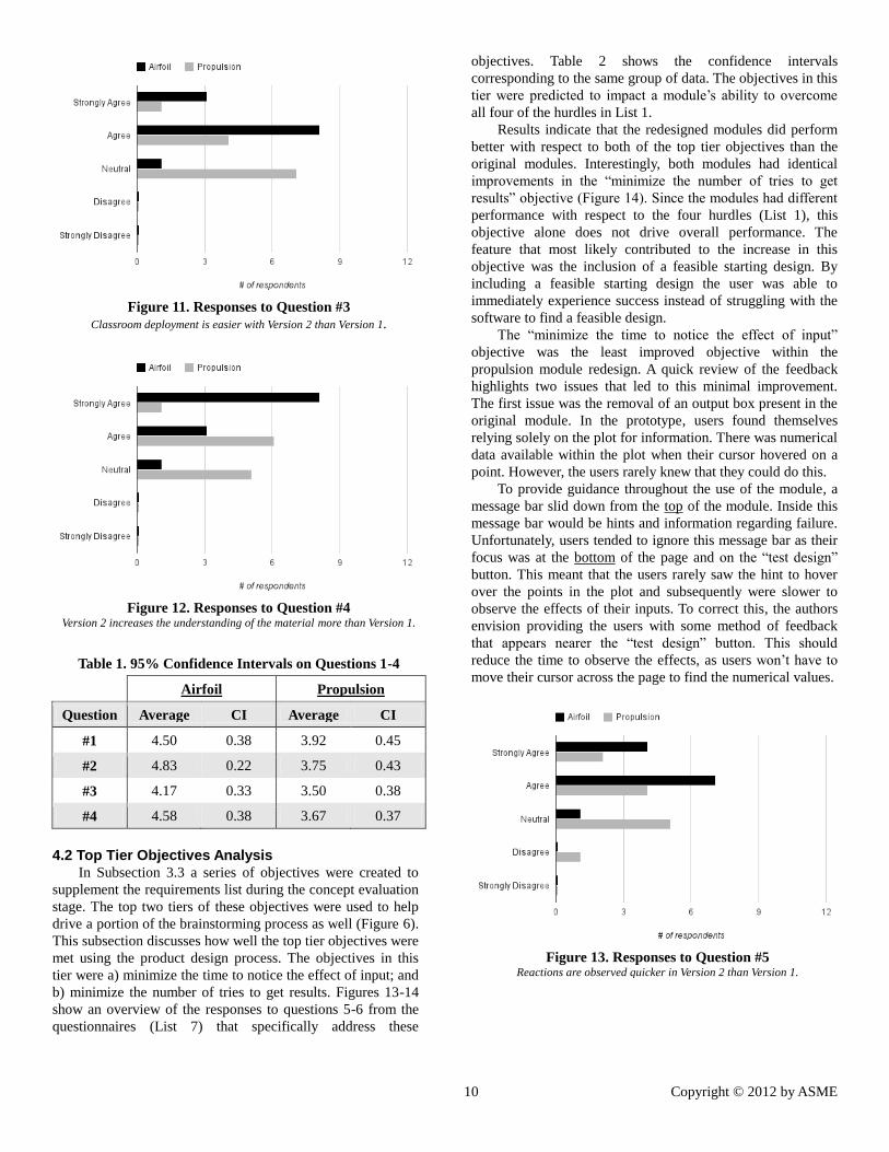
Figure 11. Responses to Question #3
Classroom deployment is easier with Version 2 than Version 1.
Figure 12. Responses to Question #4 Version 2 increases the understanding of the material more than Version 1.
Table 1. 95% Confidence Intervals on Questions 1-4
Airfoil Propulsion
Question Average CI Average CI
#1 4.50 0.38 3.92 0.45
#2 4.83 0.22 3.75 0.43
#3 4.17 0.33 3.50 0.38
#4 4.58 0.38 3.67 0.37
4.2 Top Tier Objectives Analysis In Subsection 3.3 a series of objectives were created to
supplement the requirements list during the concept evaluation
stage. The top two tiers of these objectives were used to help
drive a portion of the brainstorming process as well (Figure 6).
This subsection discusses how well the top tier objectives were
met using the product design process. The objectives in this
tier were a) minimize the time to notice the effect of input; and
b) minimize the number of tries to get results. Figures 13-14
show an overview of the responses to questions 5-6 from the
questionnaires (List 7) that specifically address these
objectives. Table 2 shows the confidence intervals
corresponding to the same group of data. The objectives in this
tier were predicted to impact a module’s ability to overcome
all four of the hurdles in List 1.
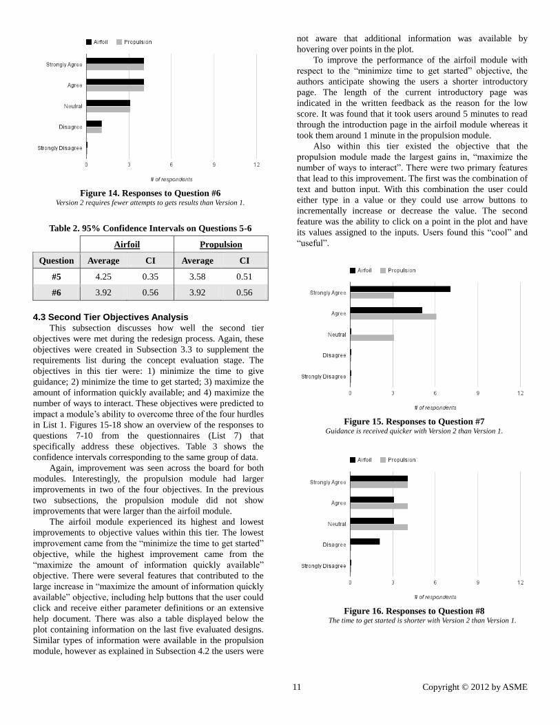
Results indicate that the redesigned modules did perform
better with respect to both of the top tier objectives than the
original modules. Interestingly, both modules had identical
improvements in the “minimize the number of tries to get
results” objective (Figure 14). Since the modules had different
performance with respect to the four hurdles (List 1), this
objective alone does not drive overall performance. The
feature that most likely contributed to the increase in this
objective was the inclusion of a feasible starting design. By
including a feasible starting design the user was able to
immediately experience success instead of struggling with the
software to find a feasible design.
The “minimize the time to notice the effect of input”
objective was the least improved objective within the
propulsion module redesign. A quick review of the feedback
highlights two issues that led to this minimal improvement.
The first issue was the removal of an output box present in the
original module. In the prototype, users found themselves
relying solely on the plot for information. There was numerical
data available within the plot when their cursor hovered on a
point. However, the users rarely knew that they could do this.
To provide guidance throughout the use of the module, a
message bar slid down from the top of the module. Inside this
message bar would be hints and information regarding failure.
Unfortunately, users tended to ignore this message bar as their
focus was at the bottom of the page and on the “test design”
button. This meant that the users rarely saw the hint to hover
over the points in the plot and subsequently were slower to
observe the effects of their inputs. To correct this, the authors
envision providing the users with some method of feedback
that appears nearer the “test design” button. This should
reduce the time to observe the effects, as users won’t have to
move their cursor across the page to find the numerical values.
Figure 13. Responses to Question #5 Reactions are observed quicker in Version 2 than Version 1.
11 Copyright © 2012 by ASME
Figure 14. Responses to Question #6 Version 2 requires fewer attempts to gets results than Version 1.
Table 2. 95% Confidence Intervals on Questions 5-6
Airfoil Propulsion
Question Average CI Average CI
#5 4.25 0.35 3.58 0.51
#6 3.92 0.56 3.92 0.56
4.3 Second Tier Objectives Analysis This subsection discusses how well the second tier
objectives were met during the redesign process. Again, these
objectives were created in Subsection 3.3 to supplement the
requirements list during the concept evaluation stage. The
objectives in this tier were: 1) minimize the time to give
guidance; 2) minimize the time to get started; 3) maximize the
amount of information quickly available; and 4) maximize the
number of ways to interact. These objectives were predicted to
impact a module’s ability to overcome three of the four hurdles
in List 1. Figures 15-18 show an overview of the responses to
questions 7-10 from the questionnaires (List 7) that
specifically address these objectives. Table 3 shows the
confidence intervals corresponding to the same group of data.
Again, improvement was seen across the board for both
modules. Interestingly, the propulsion module had larger
improvements in two of the four objectives. In the previous
two subsections, the propulsion module did not show
improvements that were larger than the airfoil module.
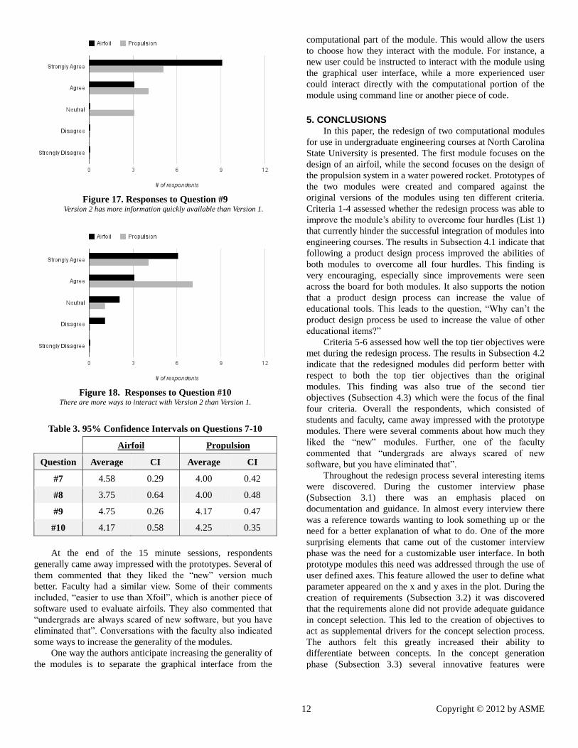
The airfoil module experienced its highest and lowest
improvements to objective values within this tier. The lowest
improvement came from the “minimize the time to get started”
objective, while the highest improvement came from the
“maximize the amount of information quickly available”
objective. There were several features that contributed to the
large increase in “maximize the amount of information quickly
available” objective, including help buttons that the user could
click and receive either parameter definitions or an extensive
help document. There was also a table displayed below the
plot containing information on the last five evaluated designs.
Similar types of information were available in the propulsion
module, however as explained in Subsection 4.2 the users were
not aware that additional information was available by
hovering over points in the plot.
To improve the performance of the airfoil module with
respect to the “minimize time to get started” objective, the
authors anticipate showing the users a shorter introductory
page. The length of the current introductory page was
indicated in the written feedback as the reason for the low
score. It was found that it took users around 5 minutes to read
through the introduction page in the airfoil module whereas it
took them around 1 minute in the propulsion module.
Also within this tier existed the objective that the
propulsion module made the largest gains in, “maximize the
number of ways to interact”. There were two primary features
that lead to this improvement. The first was the combination of
text and button input. With this combination the user could
either type in a value or they could use arrow buttons to
incrementally increase or decrease the value. The second
feature was the ability to click on a point in the plot and have
its values assigned to the inputs. Users found this “cool” and
“useful”.
Figure 15. Responses to Question #7 Guidance is received quicker with Version 2 than Version 1.
Figure 16. Responses to Question #8 The time to get started is shorter with Version 2 than Version 1.
12 Copyright © 2012 by ASME
Figure 17. Responses to Question #9 Version 2 has more information quickly available than Version 1.
Figure 18. Responses to Question #10 There are more ways to interact with Version 2 than Version 1.
Table 3. 95% Confidence Intervals on Questions 7-10
Airfoil Propulsion
Question Average CI Average CI
#7 4.58 0.29 4.00 0.42
#8 3.75 0.64 4.00 0.48
#9 4.75 0.26 4.17 0.47
#10 4.17 0.58 4.25 0.35
At the end of the 15 minute sessions, respondents
generally came away impressed with the prototypes. Several of
them commented that they liked the “new” version much
better. Faculty had a similar view. Some of their comments
included, “easier to use than Xfoil”, which is another piece of
software used to evaluate airfoils. They also commented that
“undergrads are always scared of new software, but you have
eliminated that”. Conversations with the faculty also indicated
some ways to increase the generality of the modules.
One way the authors anticipate increasing the generality of
the modules is to separate the graphical interface from the
computational part of the module. This would allow the users
to choose how they interact with the module. For instance, a
new user could be instructed to interact with the module using
the graphical user interface, while a more experienced user
could interact directly with the computational portion of the
module using command line or another piece of code.
5. CONCLUSIONS
In this paper, the redesign of two computational modules
for use in undergraduate engineering courses at North Carolina
State University is presented. The first module focuses on the
design of an airfoil, while the second focuses on the design of
the propulsion system in a water powered rocket. Prototypes of
the two modules were created and compared against the
original versions of the modules using ten different criteria.
Criteria 1-4 assessed whether the redesign process was able to
improve the module’s ability to overcome four hurdles (List 1)
that currently hinder the successful integration of modules into
engineering courses. The results in Subsection 4.1 indicate that
following a product design process improved the abilities of
both modules to overcome all four hurdles. This finding is
very encouraging, especially since improvements were seen
across the board for both modules. It also supports the notion
that a product design process can increase the value of
educational tools. This leads to the question, “Why can’t the
product design process be used to increase the value of other
educational items?”
Criteria 5-6 assessed how well the top tier objectives were
met during the redesign process. The results in Subsection 4.2
indicate that the redesigned modules did perform better with
respect to both the top tier objectives than the original
modules. This finding was also true of the second tier
objectives (Subsection 4.3) which were the focus of the final
four criteria. Overall the respondents, which consisted of
students and faculty, came away impressed with the prototype
modules. There were several comments about how much they
liked the “new” modules. Further, one of the faculty
commented that “undergrads are always scared of new
software, but you have eliminated that”.
Throughout the redesign process several interesting items
were discovered. During the customer interview phase
(Subsection 3.1) there was an emphasis placed on
documentation and guidance. In almost every interview there
was a reference towards wanting to look something up or the
need for a better explanation of what to do. One of the more
surprising elements that came out of the customer interview
phase was the need for a customizable user interface. In both
prototype modules this need was addressed through the use of
user defined axes. This feature allowed the user to define what
parameter appeared on the x and y axes in the plot. During the
creation of requirements (Subsection 3.2) it was discovered
that the requirements alone did not provide adequate guidance
in concept selection. This led to the creation of objectives to
act as supplemental drivers for the concept selection process.
The authors felt this greatly increased their ability to
differentiate between concepts. In the concept generation
phase (Subsection 3.3) several innovative features were
13 Copyright © 2012 by ASME
identified to address many of the customer needs. One of the
more interesting features was the ability for users to hover over
points in the plot and see the information (design and
performance) associated with it. Additionally, the users could
click on a point in the plot and have their inputs changed to
match the selected point. This allowed users to quickly return
back to a “good” design for further exploration.
As with most product design, there is a need to iterate as
new issues and solutions are discovered. This product design
experience was no different. Within the airfoil module the
authors anticipate changes to the introductory phase of the
module. Feedback from the respondents indicated that it took a
“long” time to read through the introduction page. The time
needed to read this page was observed to be roughly 5
minutes. The authors anticipate focusing the content on this
page to reduce the time needed. Within the propulsion module
it was found that the user focused on the bottom of the page
where the “test design” button was. This meant that many of
the users did not notice the information being displayed at the
top of the page. To remedy this issue the authors anticipate
bringing the critical information closer to the “test design”
button.
The final area of change anticipated for these modules is
the separation of the graphical user interface from the
computational portion of the module. This change is needed
for two reasons. The first reason is that the faculty have
repeatedly expressed the need to have modules that are more
general purpose. It is presumed that a separate computational
portion of the code would allow for a specific module to be
used in more than one chapter or course either by utilizing
different functionalities at different times, possibly with
different graphical user interfaces. The goal of this is to reduce
the time needed for both students and faculty to gain a level of
comfort with the software. The second reason for the
separation is to allow the modules to be integrated into other
software. This is especially important for the next phase of this
research which will look at student interactions in
multidisciplinary design environments.
This next phase of this research possesses similar
motivation to this paper; that motivation being industry needs
more engineers that are capable of working on
multidisciplinary design problems. As mentioned in the
introduction, multidisciplinary design problems possess too
much information and complexity for a single person to be
able to handle all the interactions that occur. However,
students cannot effectively learn about multidisciplinary design
until they have a foundation in traditional engineering design,
hence the need for designing the modules in this paper. The
authors anticipate that there are different ways to display
design and performance information to students such that they
will be encouraged to explore the design space as well as
converge to an optimal design faster.
ACKNOWLEDGMENTS We gratefully acknowledge support from the National
Science Foundation through NSF Grant No. EEC-1037677,
and from NC State University. Any opinions, findings, and
conclusions presented in this paper are those of the authors and
do not necessarily reflect the views of the National Science
Foundation.
REFERENCES [1] 2011, “Boeing Sees 787 as Jet Lineup’s ‘Backbone’
With Delay Ending,” BusinessWeek: Homepage.
[2] “Boeing celebrates 787 delivery as program’s costs top
$32 billion,” The Seattle Times.
[3] National Science Board, 2007, “Moving Forward to
Improve Engineering Education,” Washington, D.C.,
NSB-07-122.
[4] National Academy of Engineering, 2010, “Grand
Challenges of Engineering.”
[5] Becz S., Pinto A., Zeidner L. E., Banaszuk A., Khire R.,
and Reeve H. M., 2010, “Design System for Managing
Complexity in Aerospace Systems,” 13th
AIAA/ISSMO
Multidisciplinary Analysis and Optimization
Conference, Fort Worth, TX, AIAA-2010-9223.
[6] Deshmukh A., and Collopy P., 2010, “Fundamental
Research into the Design of Large-Scale Complex
Systems,” 13th
AIAA/ISSMO Multidisciplinary Analysis
and Optimization Conference, Fort Worth, TX, AIAA-
2010-9320.
[7] Agte J., De Weck O., Sobieszczanski-Sobieski J.,
Arendsen P., Morris A., and Spieck M., 2010, “MDO:
Assessment and Direction for Advancement—an
Opinion of One International Group,” Structural and
Multidisciplinary Optimization, 40(1), pp. 17–33.
[8] Martins J. R. R. A., 2010, “The Future of
Multidisciplinary Design Optimization (MDO):
Advancing the Design of Complex Engineered
Systems,” NSF Workshop Report, September 16, 2010/
[9] Mason W. H., Gürdal Z., and Haftka R. T., 1995,
“Experience in Multidisciplinary Design Education,”
ASEE Annual Conference, Anaheim, CA.
[10] Dutson A. J., Todd R. H., Magleby S. P., and Sorensen
C. D., 1997, “A Review of Literature on Teaching
Engineering Design through Project-oriented Capstone
Courses,” Journal of Engineering Education, 86, pp.
17–28.
[11] Sheppard K., and Gallois B., 1999, “The Design Spine:
Revision of the Engineering Curriculum to Include a
Design Experience Each Semester,” American Society
for Engineering Education Annual Conference
Proceedings.
[12] Hadim H. A., and Esche S. K., 2002, “Enhancing the
Engineering Curriculum through Project-based
Learning,” Frontiers in Education, 32nd Annual, pp.
F3F–1 – F3F–6 vol.2, 10.1109/FIE.2002.1158200.
[13] Jamieson L., and Lohmann J., 2009, “Creating a Culture
for Scholarly and Systematic Innovation in Engineering
Education: Ensuring US engineering has the right
people with the right talent for a global society,”
American Society of Engineering Educators (ASEE).
[14] Culver R. S., and others, 1990, “Gaining Professional
Expertise through Design Activities.,” Engineering
Education, 80(5), pp. 533–36.
14 Copyright © 2012 by ASME
[15] Koen B. V., 1994, “Toward a Strategy for Teaching
Engineering Design,” Journal of Engineering
Education, 83(3), pp. 193–201.
[16] Radcliffe D. F., and Lee T. Y., 1989, “Design Methods
used by Undergraduate Engineering Students,” Design
Studies, 10(4), pp. 199–207.
[17] Ainsworth S., Honey M., Johnson W. L., Koedinger K.
R., Muramatsu B., Pea R. D., Recker M., Weimar S.,
and others, 2005, “Cyberinfrastructure for Education
and Learning for the Future: a vision and research
agenda,” Computing Research Association report.
[18] Mund F. C., Kalfas A. I., and Abhari R. S., 2002,
“Integration of Software Tools into a Multidisciplinary
Undergraduate Student Design Project,” Proceedings of
the 2002 American Society for Engineering Education
Annual Conference & Exposition.
[19] Philpot T. A., 2000, “MDSolids: Software to Bridge the
Gap between Lectures and Homework in Mechanics of
Materials,” International Journal of Engineering
Education, 16(5), pp. 401–407.
[20] Kosasih P., and Tieu A., 2007, “Incorporating the
Development of a Graphical User Interface in Courses
Teaching Numerical Methods for Engineers,”
International Journal of Mechanical Engineering
Education, 35(1), pp. 46–55.
[21] Marghitu D. B., and Raju P., 2009, “Mechanism analysis
with Mathematica,” International Journal of
Mechanical Engineering Education, 37(2), pp. 130–
143.
[22] Szykman S., Sriram R. D., Bochenek C., and Racz J.,
1998, “The NIST Design Repository Project,” Advances
in Soft Computing-Engineering Design and
Manufacturing, pp. 5–19.
[23] Stroble J. K., Stone R. B., and Watkins S. E., 2009,
“Assessing How Digital Design Tools Affect Learning
of Engineering Design Concepts,” 2009 ASME
IDETC/CIE, Design Education Conference, San Diego,
CA, DETC2009/DEC-86708.
[24] Kurtoglu T., Campbell M. I., and Linsey J. S., 2009,
“An Experimental Study on the Effects of a
Computational Design Tool on Concept Generation,”
Design Studies, 30(6), pp. 676–703.
[25] Graphsynth, 2010, “Software for Generative Grammars
and Creative Search.”, http://graphsynth.com.
[26] Swantner A., and Campbell M. I., 2009, “Automated
Synthesis and Optimization of Gear Train Topologies,”
2009 ASME IDETC/CIE, Design Automation
Conference, San Diego, CA, DETC2009-86780.
[27] FunctionCAD, 2010, “Repository Entry Application –
Design Engineering Lab.”
[28] Regli W. C., Anthony L., Cicirello V., John J., Qin X.,
Shapirshteyn Y., and Zaychik V., 2006, The Engineering
Design Repositories Project.
[29] English K. W., Hulme K. F., and Lewis K. E., 2008,
“Engaging High School Women in Engineering Design
Using Cyberinfrastructure,” 2008 ASME IDETC/CIE,
Brooklyn, NY, DETC2008-49896.
[30] Devendorf M., Lewis K., Simpson T. W., Stone R. B.,
and Regli W. C., 2007, “Evaluating the use of
cyberinfrastructure in the classroom to enhance product
dissection,” 2007 ASME IDETC/CIE, Las Vegas, NV,
DETC2007-35549.
[31] Gurnani A. P., and Lewis K., 2007, “The Use of Really
Simple Syndication (RSS) Feeds for Improved
Information Communication in Decentralized Decision
Systems,” 2007 ASME IDETC/CIE, Las Vegas, NV,
DETC2007-35530.
[32] Stump G., Yukish M., Martin J. D., and Simpson T.,
2004, “The ARL Trade Space Visualizer - An
engineering decision-making tool,” 10th AIAA/ISSMO
Multidisciplinary Analysis and Optimization
Conference, Albany, NY, AIAA-2004-4568.
[33] Simpson T. W., Spencer D. B., Yukish M. A., and Stump
G., 2008, “Visual Steering Commands and Test
Problems to Support Research in Trade space
Exploration,” 12th AIAA/ISSMO Multidisciplinary
Analysis and Optimization Conference, Victoria, BC,
AIAA-2008-6085.
[34] Zhang X. L., Simpson T. W., Frecker M., and Lesieutre
G., 2009, “Supporting Trade Space Exploration of
Multi-Dimensional Data with Interactive Multi-Scale
Nested Clustering and Aggregation,” 2009 ASME
IDETC/CIE, San Diego, CA., DETC2009-87045.
[35] Balling R., 1999, “Design by shopping: A new
paradigm?” Proceedings of the Third World Congress of
Structural and Multidisciplinary Optimization
(WCSMO-3), pp. 295–297.
[36] Wolf D., Simpson T. W., and Zhang X., 2009, “A
Preliminary Study of Novice and Expert Users’
Decision-making Procedures during Visual Trade Space
Exploration,” ASME Design Engineering Technical
Conferences—Design Automation Conference, ASME,
San Diego, CA, DETC2009/DAC-87294.
[37] Ahlström J., and Christie M., 2005, “Using a Matlab
Exercise to Improve the Teaching and Learning of Heat
Conduction during Welding,” International Journal of
Engineering Education, 21(5), pp. 769–777.
[38] Feisel L. D., and Rosa A. J., 2005, “The Role of the
Laboratory in Undergraduate Engineering Education,”
Journal of Engineering Education, 94(1), pp. 121–130.
[39] Otto K., and Wood K., 2000, Product Design:
Techniques in Reverse Engineering and New Product
Development, Prentice Hall.
[40] Pahl G., Beitz W., Schulz H.-J., and Jarecki U., 2007,
Engineering Design: A Systematic Approach, Springer.
[41] Ulrich K. T., and Eppinger S. D., 2006, Product Design
and Development, McGraw-Hill.
[42] “MATLAB - The Language of Technical Computing.”
[43] Likert R., 1932, “A Technique for the Measurement of
Attitudes,” Archives of psychology.