the cavity magnetron: not just a british inventioned-thelen.org/earlymagnetron-r-.pdfieee antennas...
TRANSCRIPT

244 IEEE Antennas and Propagation Magazine, Vol. 55, No. 5, October 2013
Historical Corner
Giuseppe PelosiUniversity of FlorenceVia di Santa Marta, 3I-50139 Florence, ItalyTel: 055-4796-759;Fax: 055-4796-767E-mail: giuseppe.pelosi@unifi .it, [email protected]
The Cavity Magnetron: Not Just a British Invention
Yves Blanchard1, Gaspare Galati2, and Piet van Genderen3
1Consulting engineer and historian, retired from Thales (France)E-mail: [email protected]
2Electronic Engineering DepartmentTor Vergata University
Via del Politecnico, 1, 00133 Rome, ItalyE-mail: [email protected]
3 Microwave Sensing, Signals & Systems Delft University of Technology
Building 36, Mekelweg 4, 2628 CD Delft, The NetherlandsE-mail: [email protected]
Abstract
It is a common belief by many people that the resonant-cavity magnetron was invented in February 1940 by Randall and Boot from Birmingham University. In reality, this is not the full story. Rather, it is a point of view mostly advocated by the winners of the Second World War, who gained a great benefi t from this microwave power tube (thanks to a two-orders-of-magnitude increase of power) in the Battle of the Atlantic, in night bombing until the fi nal collapse of the German Reich, and in many other operations. This paper discusses the contributions by other nations, mainly France, but also Germany, Japan, The Netherlands, the Czech Republic, the USSR, and even more, to the cavity magnetron and to its roots.
1. The Cavity Magnetron and Its Practical Signifi cance as a
Major Innovation in 1940-1945
The industrial development of the cavity magnetron, and the subsequent development of high-power airborne and
surface microwave radar, appear as a typical case of “major innovation,” i.e., according to the defi nition often used by technology historians, an invention that leads to practical – and profi table – use serving some recognized need of our society. It has been treated in many books (see, for instance, [1-5]) and in many papers. The most vivid description was probably in [1], a book written by the Welsh physicist, Edward G. Bowen (1911-1991), a prime actor in the develop ment of microwave and airborne radar. Just looking at the titles of these books, it is evident that in many cases the “British (or American) pride” of the winners of the Second World War, as well as the trend to exalt history, seems to pre vail over objectiveness and completeness. Some notable exceptions are from Canadian, Italian, and French authors, as in [6-8]. They are among the very few sources mentioning the decision of the British Air Ministry to inform – under military secrecy – the dominion governments of the most industrialized Commonwealth nations (Canada, Australia, South Africa) of the developments in the fi eld of radar, pushing ahead the development of radar in those nations (see, for instance, the last chapter of [9]).
Like radar itself, the cavity magnetron was “a simultane-ous invention” [7] in different nations. However, it is gener ally recognized that Birmingham University implemented the fi rst high-power version of this microwave device that was easily reproducible and suited for mass production.
Prof. Marcus (Mark) L. E. Oliphant (1901-2000), an Australian physicist, came to Birmingham University in 1937, where he worked on high-power radar under contracts with the British Admiralty. As a matter of fact, in 1938-1940, there were strong requirements to improve the angular resolution of both the airborne radars and the surface radars (metric-wave airborne radars – which were in operation before the micro-wave magnetron was invented – could only detect targets at a distance less than the height above the terrain of the own air-craft, due to the unavoidable refl ections from land or sea). A basic requirement was a power of at least 1 kW at the optimal wavelength, which was evaluated to be approximately 10 cm. It is well known that at Birmingham University, the cavity magnetron was improved by John T. Randall [10] and Henry A. H. Boot, two researchers of Oliphant’s group (see Fig ure 1). On February 21, 1940, their experimental device, sealed by wax and permanently connected to a vacuum pump, and oscillating at a wavelength of 9.8 cm, produced the very signifi cant power of 400 W, two orders of magnitude above the levels previously available at that wavelength. The work at Birmingham proceeded quickly, arriving in a few weeks at power levels of the order of kilowatts (later, in September 1940, Randall and Boot developed a 14-cavity magnetron operating at 5 cm, and another magnetron with six cavities operating at 3 cm; in May, 1941, they succeeded in producing 1 MW at 10 cm: a three-
orders-of-magnitude improvement with respect to their fi rst prototype!).
Of course, the early devices by Randall and Boot were laboratory prototypes, not suited for fi eld operation. In April, 1940, the Admiralty signed a contract with the General Elec-tric Company Ltd. (GEC) at Wembley to produce an opera-tional device. First of all, this device was to operate with nei-ther vacuum pumps nor an external generator of the magnetic fi eld. The water-cooled device No. 1 (the following devices were air-cooled) oscillated for the fi rst time on June 29, gen-erating 500 W at 9.8 cm. By mid-August, a bulky prototype of a radar with a 10 cm magnetron and two small paraboloids as transmitting and receiving antennas detected the fi rst micro-wave echoes of an aircraft [3, 11]. Eric C. Stanley Megaw (1908-1956), team leader of the GEC laboratories, modifi ed some important elements of the Birmingham design, including the coating of the cathode with oxides. Soon, in September, the power reached 100 kW at 10 cm wavelength. The fi rst airborne trials were done with a twin-engine Blenheim in March, 1941, and the operational use soon followed.
In mid-1940, with the German troops in Paris and the French armistice (June 14), it was clear to the British that the industrial power of Germany and occupied nations was going to outperform that of the United Kingdom. The UK would risk quickly losing the (more and more technological) war. The authoritative professor and scientifi c advisor to the British government, Sir Henry T. Tizard (1885-1959), Chairman of the Aeronautical Research Committee since 1933, suggested disclosing the scientifi c and technical information to the Unites States government, so that their enormous potential for development and manufacturing could be put to effective use. On August 9, W. Churchill approved the project, paving the way for the “British Technical and Scientifi c Mission to the
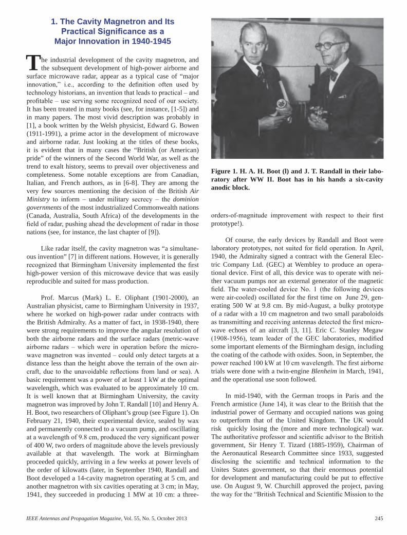
Figure 1. H. A. H. Boot (l) and J. T. Randall in their labo-ratory after WW II. Boot has in his hands a six-cavity anodic block.
AP_Mag_Oct_2013_Final.indd 244 12/15/2013 3:55:13 PM
IEEE Antennas and Propagation Magazine, Vol. 55, No. 5, October 2013 245
Historical Corner
Giuseppe PelosiUniversity of FlorenceVia di Santa Marta, 3I-50139 Florence, ItalyTel: 055-4796-759;Fax: 055-4796-767E-mail: giuseppe.pelosi@unifi .it, [email protected]
The Cavity Magnetron: Not Just a British Invention
Yves Blanchard1, Gaspare Galati2, and Piet van Genderen3
1Consulting engineer and historian, retired from Thales (France)E-mail: [email protected]
2Electronic Engineering DepartmentTor Vergata University
Via del Politecnico, 1, 00133 Rome, ItalyE-mail: [email protected]
3 Microwave Sensing, Signals & Systems Delft University of Technology
Building 36, Mekelweg 4, 2628 CD Delft, The NetherlandsE-mail: [email protected]
Abstract
It is a common belief by many people that the resonant-cavity magnetron was invented in February 1940 by Randall and Boot from Birmingham University. In reality, this is not the full story. Rather, it is a point of view mostly advocated by the winners of the Second World War, who gained a great benefi t from this microwave power tube (thanks to a two-orders-of-magnitude increase of power) in the Battle of the Atlantic, in night bombing until the fi nal collapse of the German Reich, and in many other operations. This paper discusses the contributions by other nations, mainly France, but also Germany, Japan, The Netherlands, the Czech Republic, the USSR, and even more, to the cavity magnetron and to its roots.
1. The Cavity Magnetron and Its Practical Signifi cance as a
Major Innovation in 1940-1945
The industrial development of the cavity magnetron, and the subsequent development of high-power airborne and
surface microwave radar, appear as a typical case of “major innovation,” i.e., according to the defi nition often used by technology historians, an invention that leads to practical – and profi table – use serving some recognized need of our society. It has been treated in many books (see, for instance, [1-5]) and in many papers. The most vivid description was probably in [1], a book written by the Welsh physicist, Edward G. Bowen (1911-1991), a prime actor in the develop ment of microwave and airborne radar. Just looking at the titles of these books, it is evident that in many cases the “British (or American) pride” of the winners of the Second World War, as well as the trend to exalt history, seems to pre vail over objectiveness and completeness. Some notable exceptions are from Canadian, Italian, and French authors, as in [6-8]. They are among the very few sources mentioning the decision of the British Air Ministry to inform – under military secrecy – the dominion governments of the most industrialized Commonwealth nations (Canada, Australia, South Africa) of the developments in the fi eld of radar, pushing ahead the development of radar in those nations (see, for instance, the last chapter of [9]).
Like radar itself, the cavity magnetron was “a simultane-ous invention” [7] in different nations. However, it is gener ally recognized that Birmingham University implemented the fi rst high-power version of this microwave device that was easily reproducible and suited for mass production.
Prof. Marcus (Mark) L. E. Oliphant (1901-2000), an Australian physicist, came to Birmingham University in 1937, where he worked on high-power radar under contracts with the British Admiralty. As a matter of fact, in 1938-1940, there were strong requirements to improve the angular resolution of both the airborne radars and the surface radars (metric-wave airborne radars – which were in operation before the micro-wave magnetron was invented – could only detect targets at a distance less than the height above the terrain of the own air-craft, due to the unavoidable refl ections from land or sea). A basic requirement was a power of at least 1 kW at the optimal wavelength, which was evaluated to be approximately 10 cm. It is well known that at Birmingham University, the cavity magnetron was improved by John T. Randall [10] and Henry A. H. Boot, two researchers of Oliphant’s group (see Fig ure 1). On February 21, 1940, their experimental device, sealed by wax and permanently connected to a vacuum pump, and oscillating at a wavelength of 9.8 cm, produced the very signifi cant power of 400 W, two orders of magnitude above the levels previously available at that wavelength. The work at Birmingham proceeded quickly, arriving in a few weeks at power levels of the order of kilowatts (later, in September 1940, Randall and Boot developed a 14-cavity magnetron operating at 5 cm, and another magnetron with six cavities operating at 3 cm; in May, 1941, they succeeded in producing 1 MW at 10 cm: a three-
orders-of-magnitude improvement with respect to their fi rst prototype!).
Of course, the early devices by Randall and Boot were laboratory prototypes, not suited for fi eld operation. In April, 1940, the Admiralty signed a contract with the General Elec-tric Company Ltd. (GEC) at Wembley to produce an opera-tional device. First of all, this device was to operate with nei-ther vacuum pumps nor an external generator of the magnetic fi eld. The water-cooled device No. 1 (the following devices were air-cooled) oscillated for the fi rst time on June 29, gen-erating 500 W at 9.8 cm. By mid-August, a bulky prototype of a radar with a 10 cm magnetron and two small paraboloids as transmitting and receiving antennas detected the fi rst micro-wave echoes of an aircraft [3, 11]. Eric C. Stanley Megaw (1908-1956), team leader of the GEC laboratories, modifi ed some important elements of the Birmingham design, including the coating of the cathode with oxides. Soon, in September, the power reached 100 kW at 10 cm wavelength. The fi rst airborne trials were done with a twin-engine Blenheim in March, 1941, and the operational use soon followed.
In mid-1940, with the German troops in Paris and the French armistice (June 14), it was clear to the British that the industrial power of Germany and occupied nations was going to outperform that of the United Kingdom. The UK would risk quickly losing the (more and more technological) war. The authoritative professor and scientifi c advisor to the British government, Sir Henry T. Tizard (1885-1959), Chairman of the Aeronautical Research Committee since 1933, suggested disclosing the scientifi c and technical information to the Unites States government, so that their enormous potential for development and manufacturing could be put to effective use. On August 9, W. Churchill approved the project, paving the way for the “British Technical and Scientifi c Mission to the
Figure 1. H. A. H. Boot (l) and J. T. Randall in their labo-ratory after WW II. Boot has in his hands a six-cavity anodic block.
AP_Mag_Oct_2013_Final.indd 245 12/15/2013 3:55:13 PM
246 IEEE Antennas and Propagation Magazine, Vol. 55, No. 5, October 2013
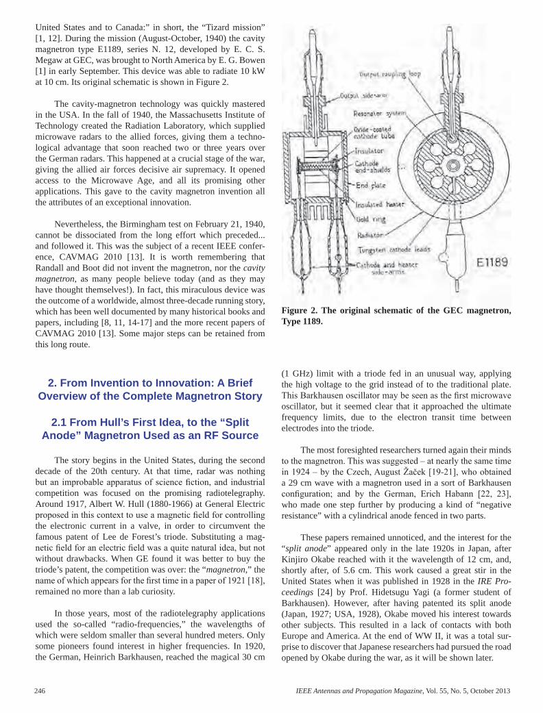
United States and to Canada:” in short, the “Tizard mission” [1, 12]. During the mission (August-October, 1940) the cavity magnetron type E1189, series N. 12, developed by E. C. S. Megaw at GEC, was brought to North America by E. G. Bowen [1] in early September. This device was able to radiate 10 kW at 10 cm. Its original schematic is shown in Figure 2.
The cavity-magnetron technology was quickly mastered in the USA. In the fall of 1940, the Massachusetts Institute of Technology created the Radiation Laboratory, which supplied microwave radars to the allied forces, giving them a techno-logical advantage that soon reached two or three years over the German radars. This happened at a crucial stage of the war, giving the allied air forces decisive air supremacy. It opened access to the Microwave Age, and all its promising other applications. This gave to the cavity magnetron inven tion all the attributes of an exceptional innovation.
Nevertheless, the Birmingham test on February 21, 1940, cannot be dissociated from the long effort which preceded... and followed it. This was the subject of a recent IEEE confer-ence, CAVMAG 2010 [13]. It is worth remembering that Randall and Boot did not invent the magnetron, nor the cavity magnetron, as many people believe today (and as they may have thought themselves!). In fact, this miraculous device was the outcome of a worldwide, almost three-decade running story, which has been well documented by many historical books and papers, including [8, 11, 14-17] and the more recent papers of CAVMAG 2010 [13]. Some major steps can be retained from this long route.
2. From Invention to Innovation: A Brief Overview of the Complete Magnetron Story
2.1 From Hull’s First Idea, to the “Split Anode” Magnetron Used as an RF Source
The story begins in the United States, during the second decade of the 20th century. At that time, radar was nothing but an improbable apparatus of science fi ction, and industrial competition was focused on the promising radiotelegraphy. Around 1917, Albert W. Hull (1880-1966) at General Electric proposed in this context to use a magnetic fi eld for controlling the electronic current in a valve, in order to circumvent the famous patent of Lee de Forest’s triode. Substituting a mag-netic fi eld for an electric fi eld was a quite natural idea, but not without drawbacks. When GE found it was better to buy the triode’s patent, the competition was over: the “magnetron,” the name of which appears for the fi rst time in a paper of 1921 [18], remained no more than a lab curiosity.
In those years, most of the radiotelegraphy applications used the so-called “radio-frequencies,” the wavelengths of which were seldom smaller than several hundred meters. Only some pioneers found interest in higher frequencies. In 1920, the German, Heinrich Barkhausen, reached the magical 30 cm
(1 GHz) limit with a triode fed in an unusual way, applying the high voltage to the grid instead of to the traditional plate. This Barkhausen oscillator may be seen as the fi rst microwave oscillator, but it seemed clear that it approached the ultimate frequency limits, due to the electron transit time between electrodes into the triode.
The most foresighted researchers turned again their minds to the magnetron. This was suggested – at nearly the same time in 1924 – by the Czech, August Žaček [19-21], who obtained a 29 cm wave with a magnetron used in a sort of Barkhausen confi guration; and by the German, Erich Habann [22, 23], who made one step further by producing a kind of “negative resistance” with a cylindrical anode fenced in two parts.
These papers remained unnoticed, and the interest for the “split anode” appeared only in the late 1920s in Japan, after Kinjiro Okabe reached with it the wavelength of 12 cm, and, shortly after, of 5.6 cm. This work caused a great stir in the United States when it was published in 1928 in the IRE Proceedings [24] by Prof. Hidetsugu Yagi (a former student of Barkhausen). However, after having patented its split anode (Japan, 1927; USA, 1928), Okabe moved his interest towards other subjects. This resulted in a lack of contacts with both Europe and America. At the end of WW II, it was a total sur-prise to discover that Japanese researchers had pursued the road opened by Okabe during the war, as it will be shown later.
Figure 2. The original schematic of the GEC magnetron, Type 1189.
2.2 The Multi-Segment Anode, and the European Studies During the 1930s
After Japan, the scene turns back again to Europe, to three eminent scientists working in industrial laboratories: Maurice Ponte (1902-1983), Figure 3, at SFR-CSF, France; Klaas Posthumus (1902-1990), Figure 4, at Philips National Lab, Netherlands; and Eric C. S. Megaw (1908-1956), Fig ure 5, at GEC, UK. They signifi cantly improved the perform ance of the “split anode” by multiplying the number of fences to get a “multisegment anode.”
Maurice Ponte, a young physicist recruited in 1930 by the French company SFR-CSF [8] to manage its Research Lab, early focused his interest on decimeter waves. He adopted Okabe’s principles, with two aims: to clarify the oscillating-mode theory, and to put the magnetron out of the laboratory for fi eld applications:
...at the time Japanese magnetrons remained with-out any practical result, they needed intensive magnetic fi elds, impractical outside a laboratory. And magnetron theory was still very fragmentary. I started the quest with a theoretical and experimen-tal study of those magnetrons which appeared the simplest to me, i.e. designed with two semi-cylin-drical anodes surrounding a cathode fi lament....
From his fi rst trials, he got 40 W at 100 MHz ( 3λ = m) with a split-anode diameter of 20 mm, and later on he went to 375 MHz ( 80λ = cm) with a 5 mm anode diameter. In 1934, he became appointed head of the SFR valve factory, and after having published a complete theoretical analysis of these results [25], he tasked his colleague, Henri Gutton, to go on with the exploration of the anode segmentation.
Klaas Posthumus at Philips (NL) set up in 1933 a split-anode magnetron that delivered about 10 W at 30 cm, and in 1934/5 he successfully developed a four-segment magnetron. However, he is mainly known for his theoretical research. In March 1935, he published in The Wireless Engineer a new theory on the magnetron oscillating mode, which he called “rotating electron cloud theory” [26]. It showed how the mag-netic-fi eld intensity giving the best effi ciency could be reduced by the multiplicity of segments. This fact is recog nized to have paved the way for the multi-segment develop ments, and later for the multi-cavity design.
E. C. S. Megaw at GEC (UK) began to study radio propa-gation at wavelengths below 60 cm nearly at the same time as M. Ponte, and Megaw developed magnetrons for use in his experiments. During this period, he fi led six patents on multi-segment anode magnetrons. However, in 1932 he failed in an attempt to make a 12-segment anode work. He became mainly a recognized theoretician, who established his reputa tion through high-level exchanges with other European scien tists, at a time when sharing of knowledge was the common scientifi c rule. As an example, he made his mark in 1934 in a public debate with K. Posthumus on the magnetron’s oscillat ing modes. This debate,
Figure 4. K. Posthumus (Philips, NL).
Figure 3. M. Ponte (CSF, Fr).
Figure 5. E. C. S. Megaw (GEC, GB).
AP_Mag_Oct_2013_Final.indd 246 12/15/2013 3:55:14 PM

IEEE Antennas and Propagation Magazine, Vol. 55, No. 5, October 2013 247
United States and to Canada:” in short, the “Tizard mission” [1, 12]. During the mission (August-October, 1940) the cavity magnetron type E1189, series N. 12, developed by E. C. S. Megaw at GEC, was brought to North America by E. G. Bowen [1] in early September. This device was able to radiate 10 kW at 10 cm. Its original schematic is shown in Figure 2.
The cavity-magnetron technology was quickly mastered in the USA. In the fall of 1940, the Massachusetts Institute of Technology created the Radiation Laboratory, which supplied microwave radars to the allied forces, giving them a techno-logical advantage that soon reached two or three years over the German radars. This happened at a crucial stage of the war, giving the allied air forces decisive air supremacy. It opened access to the Microwave Age, and all its promising other applications. This gave to the cavity magnetron inven tion all the attributes of an exceptional innovation.
Nevertheless, the Birmingham test on February 21, 1940, cannot be dissociated from the long effort which preceded... and followed it. This was the subject of a recent IEEE confer-ence, CAVMAG 2010 [13]. It is worth remembering that Randall and Boot did not invent the magnetron, nor the cavity magnetron, as many people believe today (and as they may have thought themselves!). In fact, this miraculous device was the outcome of a worldwide, almost three-decade running story, which has been well documented by many historical books and papers, including [8, 11, 14-17] and the more recent papers of CAVMAG 2010 [13]. Some major steps can be retained from this long route.
2. From Invention to Innovation: A Brief Overview of the Complete Magnetron Story
2.1 From Hull’s First Idea, to the “Split Anode” Magnetron Used as an RF Source
The story begins in the United States, during the second decade of the 20th century. At that time, radar was nothing but an improbable apparatus of science fi ction, and industrial competition was focused on the promising radiotelegraphy. Around 1917, Albert W. Hull (1880-1966) at General Electric proposed in this context to use a magnetic fi eld for controlling the electronic current in a valve, in order to circumvent the famous patent of Lee de Forest’s triode. Substituting a mag-netic fi eld for an electric fi eld was a quite natural idea, but not without drawbacks. When GE found it was better to buy the triode’s patent, the competition was over: the “magnetron,” the name of which appears for the fi rst time in a paper of 1921 [18], remained no more than a lab curiosity.
In those years, most of the radiotelegraphy applications used the so-called “radio-frequencies,” the wavelengths of which were seldom smaller than several hundred meters. Only some pioneers found interest in higher frequencies. In 1920, the German, Heinrich Barkhausen, reached the magical 30 cm
(1 GHz) limit with a triode fed in an unusual way, applying the high voltage to the grid instead of to the traditional plate. This Barkhausen oscillator may be seen as the fi rst microwave oscillator, but it seemed clear that it approached the ultimate frequency limits, due to the electron transit time between electrodes into the triode.
The most foresighted researchers turned again their minds to the magnetron. This was suggested – at nearly the same time in 1924 – by the Czech, August Žaček [19-21], who obtained a 29 cm wave with a magnetron used in a sort of Barkhausen confi guration; and by the German, Erich Habann [22, 23], who made one step further by producing a kind of “negative resistance” with a cylindrical anode fenced in two parts.
These papers remained unnoticed, and the interest for the “split anode” appeared only in the late 1920s in Japan, after Kinjiro Okabe reached with it the wavelength of 12 cm, and, shortly after, of 5.6 cm. This work caused a great stir in the United States when it was published in 1928 in the IRE Proceedings [24] by Prof. Hidetsugu Yagi (a former student of Barkhausen). However, after having patented its split anode (Japan, 1927; USA, 1928), Okabe moved his interest towards other subjects. This resulted in a lack of contacts with both Europe and America. At the end of WW II, it was a total sur-prise to discover that Japanese researchers had pursued the road opened by Okabe during the war, as it will be shown later.
Figure 2. The original schematic of the GEC magnetron, Type 1189.
2.2 The Multi-Segment Anode, and the European Studies During the 1930s
After Japan, the scene turns back again to Europe, to three eminent scientists working in industrial laboratories: Maurice Ponte (1902-1983), Figure 3, at SFR-CSF, France; Klaas Posthumus (1902-1990), Figure 4, at Philips National Lab, Netherlands; and Eric C. S. Megaw (1908-1956), Fig ure 5, at GEC, UK. They signifi cantly improved the perform ance of the “split anode” by multiplying the number of fences to get a “multisegment anode.”
Maurice Ponte, a young physicist recruited in 1930 by the French company SFR-CSF [8] to manage its Research Lab, early focused his interest on decimeter waves. He adopted Okabe’s principles, with two aims: to clarify the oscillating-mode theory, and to put the magnetron out of the laboratory for fi eld applications:
...at the time Japanese magnetrons remained with-out any practical result, they needed intensive magnetic fi elds, impractical outside a laboratory. And magnetron theory was still very fragmentary. I started the quest with a theoretical and experimen-tal study of those magnetrons which appeared the simplest to me, i.e. designed with two semi-cylin-drical anodes surrounding a cathode fi lament....
From his fi rst trials, he got 40 W at 100 MHz ( 3λ = m) with a split-anode diameter of 20 mm, and later on he went to 375 MHz ( 80λ = cm) with a 5 mm anode diameter. In 1934, he became appointed head of the SFR valve factory, and after having published a complete theoretical analysis of these results [25], he tasked his colleague, Henri Gutton, to go on with the exploration of the anode segmentation.
Klaas Posthumus at Philips (NL) set up in 1933 a split-anode magnetron that delivered about 10 W at 30 cm, and in 1934/5 he successfully developed a four-segment magnetron. However, he is mainly known for his theoretical research. In March 1935, he published in The Wireless Engineer a new theory on the magnetron oscillating mode, which he called “rotating electron cloud theory” [26]. It showed how the mag-netic-fi eld intensity giving the best effi ciency could be reduced by the multiplicity of segments. This fact is recog nized to have paved the way for the multi-segment develop ments, and later for the multi-cavity design.
E. C. S. Megaw at GEC (UK) began to study radio propa-gation at wavelengths below 60 cm nearly at the same time as M. Ponte, and Megaw developed magnetrons for use in his experiments. During this period, he fi led six patents on multi-segment anode magnetrons. However, in 1932 he failed in an attempt to make a 12-segment anode work. He became mainly a recognized theoretician, who established his reputa tion through high-level exchanges with other European scien tists, at a time when sharing of knowledge was the common scientifi c rule. As an example, he made his mark in 1934 in a public debate with K. Posthumus on the magnetron’s oscillat ing modes. This debate,
Figure 4. K. Posthumus (Philips, NL).
Figure 3. M. Ponte (CSF, Fr).
Figure 5. E. C. S. Megaw (GEC, GB).
AP_Mag_Oct_2013_Final.indd 247 12/15/2013 3:55:14 PM

248 IEEE Antennas and Propagation Magazine, Vol. 55, No. 5, October 2013
published in Nature [27], was con cluded by his agreement with Posthumus’s “rotating fi eld the ory,” which shed new light on the ensuing research.
He also developed contacts with Ponte and his team at CSF, more and more closely spaced over the years, marked by regular visits from one laboratory to the other. The question discussed dealt again with the multi-segment anode: did it work under a new oscillating mode, and was the number of segments limited? The most common opinion (also shared by Posthumus) was that beyond four segments, the tube’s effi ciency quickly fell. The results shown by Gutton had a major impact on Megaw’s understanding of the oscillating mecha nisms, and according to Brittain [15], they “were later credited with having exerted a ‘profound effect’ on British thinking about the cavity magnetron.”
These activities, supported by industrial laboratories, give evidence to the interest that radio companies maintained for the magnetron during the 1930s. A statistical analysis of the patents fi led in that period [28] confi rms it, showing that about 2000 magnetron patents were fi led by the major compa nies between 1920 and 1945. They came mainly from Euro pean countries (for a total amount of 861 patents), but the US industry was not so far off, with 727 patents. Many newcom ers appeared in the fi eld, such as E. Linder and J. H. Fremlin, followed (in order of productivity) by A. Haeff, C. Hansell, and A. Samuel. Special mention must be made of G. R. Kilgore, who was probably at that time the most important American theorist. In Europe, in addition to the trio previously mentioned, the most-prolifi c inventor was the German, H. E. Holmann (1899-1960), an independent engineer consultant at Telefunken, later with the fi rm GEMA, where he contributed to the design of the famous ship-borne radar Seetakt [29].
Henri Gutton (1905-1984), who succeeded M. Ponte in 1934, has attached his name to the more-extended study that was made on the segmented anode. Over the ensuing fi ve years, he repeated extensive and systematic experiments on more and more complex anode geometries, with six to eight een segments of various shapes (see Figure 6). They typically delivered around 10 W on wavelengths varying from 20 cm to 6 cm. Two patents were fi led, on April 17, 1937, and Decem ber 10, 1937, and a conclusive paper was published in 1938 [30].
In 1938, he made his choice for an anode with eight seg ments, imbricated and fi xed four by four on two opposite metallic discs, according to an architecture named “squirrel cage.” As soon as the fi rst trials began, he observed oscilla tions at some 1.8 GHz, obtained with signifi cantly reduced voltage and magnetic fi eld.
In Figure 6, the “No. 8 tube” is shown, issued from these trials, with a detail of the 2 4× interlaced segments, cooled by the small fl anges that can be seen along each segment, and the valve inserted in its permanent magnet. Marketed under the designation “M16,” this valve gave 10 W at 16λ = cm, with a 15% effi ciency, under 765 V for the anode voltage and 430 gauss for the magnetic fi eld. Figure 6. Gutton’s magnetron (M-16 No. 8).
2.3 First Attempts at Application in Early Radars
Most of the work related to the magnetron applications was aimed at directive radio-link applications. However, some early attempts to use them as RF sources for radar can be found as early as 1933, when Rudolf Kühnhold in Germany used a Posthumus 40W/48 cm magnetron in his fi rst trials for naval radar (which led later to the famous Freya [7, 8, 29]). In the same year in the US, William D. Hershberger, an engineer at the Signal Corps Laboratories, built a continuous-wave detection device using a 9 cm RCA magnetron, which he tested in August 1934 on ships entering the New York Bay. In 1936 in Holland, C. H. Staal also used a Philips 10 W/30 cm magnetron for detection trials ordered by the Royal Nether lands Navy [31]. None of these attempts was succeeded by further developments. However, they were indeed on the way to heralding a major innovation coming up.
The most practical application in France was Gutton’s project for a “naval obstacle detector,” in fact a very early decimetric radar. He submitted his idea to M. Ponte in April 1934, and he patented this equipment on July 20, 1937 [8]. It is worth noting these dates in relation to the famous Watson-Watt memorandum (February 12, 1935). The idea looks like a revival of the Hülsmeyer’s Telemobiloskop, of which Gutton had never heard, as usual at that time. Unlike this prior event, his project found an immediate opportunity for exploitation: in January 1935, the owners of the liner “Normandie,” at that time to be completed, requested that the ship be equipped with the new system. It was mounted onboard very quickly, to have its fi rst trials at sea from mid-1935 [32].
2.4 The Cathode Question
As higher powers were reached, a second point became a major subject discussed between Gutton and Megaw: how to adapt the shape and the structure of the cathode in a multi-segment architecture? Nearly all magnetrons used as a cathode a pure tungsten fi lament, centered on the anode’s axis, and directly heated by the ohmic effect. This fi tted well with small tube diameters. However, with the larger diameters of the multi-segment anodes, the result was that the effi ciency reduced as the inter-electrode space enlarged. As Megaw explained later, there was therefore a strong relationship between the two points they were discussing [33]:
...the restriction of established practice to small cathodes was related to the general conclusion that the use of more than 4 segments was of little prac tical value; together (these two assumptions) formed a kind of vicious circle which prevented the combination of many segments with large cath odes.
The matter advanced in 1937 when Megaw used a thoriated-tungsten cathode with some success in his E-880, shaped into a
spiral to increase its diameter, and he advised Gutton to test it in the M16. This gave nearly 50 W in early 1939, still not enough for the needs of new radar applications. Gutton decided then to insert a cylindrical cathode in his tube, coated with oxide, and indirectly heated by a separate fi lament. This technique, which was used in classical triodes, proved imme diately successful for various reasons: easier cooling, higher resistance to early burning, and better effi ciency due to the inter-electrode space reduction. However, the main reason was found later by Megaw: under the condition of so-called “back bombardment,” the oxide-coated cathode was best able to pro duce electron retroemission, enhancing the general effi ciency of the tube.
A new oxide fi tted to M16, giving a peak power of up to 300 W, was shown to Megaw on his last visit in June 1939, and it was decided to provide him with a second sample to be tested at Wembley. This promised exchange was delayed by the outbreak of war, and in the meantime, Gutton still improved his record: in late 1939, a new eight-segment anode and oxide-coated cathode M16 delivered a peak-power record of 1 kW at 16 cm.
The last step of the story is quite dramatic. In April 1940, the war situation had become very critical in France. Under this increasing threat, a few days before the German army broke through the front line and rushed to Paris, Dr. Ponte himself crossed the Channel with the admission of the French government, bringing to Wembley two samples of the prom-ised new M16 [8]. It was immediately tested by Megaw, and it provided a performance that became decisive in the follow-up.
2.5 Cavities Versus Segments: The Final Step for a Defi nitive Solution
One can wonder if the success of the multi-segment anode could have been an obstacle that delayed the last and essential evolution towards the cavity anode. In fact, it is now well established that the cavity principle did not appear by miracle on one day of September 1940, in a secret laboratory of the Birmingham University! Conversely, it resulted from a lot of other trials, probably inspired by the cavity klystron of Hansen [34], which cannot be detailed here, but only illus-trated by some fi gures that clearly show the existence of the cavity-anode idea since 1934. They were extracted as exam ples from patents fi led by Arthur Samuel (Bell laboratories, USA, 1934) [35], Hans Eric Hollmann (Telefunken, Germany, 1935) [36], Wilhelm Engberg (Telefunken Germany, 1938), [8, 37], and N. F. Alekseev and D. D. Malairov (USSR, 1937) [38] (see Figure 7).
Special attention must be paid to the Russian work con ducted in 1936-37 at the University of Leningrad by N. F. Alekseev and D. D. Malairov. With four cavities, their experimental device gave 300 W at 9 cm. However, it was unable to go further without burning the cathode, a question they had not solved.
AP_Mag_Oct_2013_Final.indd 248 12/15/2013 3:55:14 PM
IEEE Antennas and Propagation Magazine, Vol. 55, No. 5, October 2013 249
published in Nature [27], was con cluded by his agreement with Posthumus’s “rotating fi eld the ory,” which shed new light on the ensuing research.
He also developed contacts with Ponte and his team at CSF, more and more closely spaced over the years, marked by regular visits from one laboratory to the other. The question discussed dealt again with the multi-segment anode: did it work under a new oscillating mode, and was the number of segments limited? The most common opinion (also shared by Posthumus) was that beyond four segments, the tube’s effi ciency quickly fell. The results shown by Gutton had a major impact on Megaw’s understanding of the oscillating mecha nisms, and according to Brittain [15], they “were later credited with having exerted a ‘profound effect’ on British thinking about the cavity magnetron.”
These activities, supported by industrial laboratories, give evidence to the interest that radio companies maintained for the magnetron during the 1930s. A statistical analysis of the patents fi led in that period [28] confi rms it, showing that about 2000 magnetron patents were fi led by the major compa nies between 1920 and 1945. They came mainly from Euro pean countries (for a total amount of 861 patents), but the US industry was not so far off, with 727 patents. Many newcom ers appeared in the fi eld, such as E. Linder and J. H. Fremlin, followed (in order of productivity) by A. Haeff, C. Hansell, and A. Samuel. Special mention must be made of G. R. Kilgore, who was probably at that time the most important American theorist. In Europe, in addition to the trio previously mentioned, the most-prolifi c inventor was the German, H. E. Holmann (1899-1960), an independent engineer consultant at Telefunken, later with the fi rm GEMA, where he contributed to the design of the famous ship-borne radar Seetakt [29].
Henri Gutton (1905-1984), who succeeded M. Ponte in 1934, has attached his name to the more-extended study that was made on the segmented anode. Over the ensuing fi ve years, he repeated extensive and systematic experiments on more and more complex anode geometries, with six to eight een segments of various shapes (see Figure 6). They typically delivered around 10 W on wavelengths varying from 20 cm to 6 cm. Two patents were fi led, on April 17, 1937, and Decem ber 10, 1937, and a conclusive paper was published in 1938 [30].
In 1938, he made his choice for an anode with eight seg ments, imbricated and fi xed four by four on two opposite metallic discs, according to an architecture named “squirrel cage.” As soon as the fi rst trials began, he observed oscilla tions at some 1.8 GHz, obtained with signifi cantly reduced voltage and magnetic fi eld.
In Figure 6, the “No. 8 tube” is shown, issued from these trials, with a detail of the 2 4× interlaced segments, cooled by the small fl anges that can be seen along each segment, and the valve inserted in its permanent magnet. Marketed under the designation “M16,” this valve gave 10 W at 16λ = cm, with a 15% effi ciency, under 765 V for the anode voltage and 430 gauss for the magnetic fi eld. Figure 6. Gutton’s magnetron (M-16 No. 8).
2.3 First Attempts at Application in Early Radars
Most of the work related to the magnetron applications was aimed at directive radio-link applications. However, some early attempts to use them as RF sources for radar can be found as early as 1933, when Rudolf Kühnhold in Germany used a Posthumus 40W/48 cm magnetron in his fi rst trials for naval radar (which led later to the famous Freya [7, 8, 29]). In the same year in the US, William D. Hershberger, an engineer at the Signal Corps Laboratories, built a continuous-wave detection device using a 9 cm RCA magnetron, which he tested in August 1934 on ships entering the New York Bay. In 1936 in Holland, C. H. Staal also used a Philips 10 W/30 cm magnetron for detection trials ordered by the Royal Nether lands Navy [31]. None of these attempts was succeeded by further developments. However, they were indeed on the way to heralding a major innovation coming up.
The most practical application in France was Gutton’s project for a “naval obstacle detector,” in fact a very early decimetric radar. He submitted his idea to M. Ponte in April 1934, and he patented this equipment on July 20, 1937 [8]. It is worth noting these dates in relation to the famous Watson-Watt memorandum (February 12, 1935). The idea looks like a revival of the Hülsmeyer’s Telemobiloskop, of which Gutton had never heard, as usual at that time. Unlike this prior event, his project found an immediate opportunity for exploitation: in January 1935, the owners of the liner “Normandie,” at that time to be completed, requested that the ship be equipped with the new system. It was mounted onboard very quickly, to have its fi rst trials at sea from mid-1935 [32].
2.4 The Cathode Question
As higher powers were reached, a second point became a major subject discussed between Gutton and Megaw: how to adapt the shape and the structure of the cathode in a multi-segment architecture? Nearly all magnetrons used as a cathode a pure tungsten fi lament, centered on the anode’s axis, and directly heated by the ohmic effect. This fi tted well with small tube diameters. However, with the larger diameters of the multi-segment anodes, the result was that the effi ciency reduced as the inter-electrode space enlarged. As Megaw explained later, there was therefore a strong relationship between the two points they were discussing [33]:
...the restriction of established practice to small cathodes was related to the general conclusion that the use of more than 4 segments was of little prac tical value; together (these two assumptions) formed a kind of vicious circle which prevented the combination of many segments with large cath odes.
The matter advanced in 1937 when Megaw used a thoriated-tungsten cathode with some success in his E-880, shaped into a
spiral to increase its diameter, and he advised Gutton to test it in the M16. This gave nearly 50 W in early 1939, still not enough for the needs of new radar applications. Gutton decided then to insert a cylindrical cathode in his tube, coated with oxide, and indirectly heated by a separate fi lament. This technique, which was used in classical triodes, proved imme diately successful for various reasons: easier cooling, higher resistance to early burning, and better effi ciency due to the inter-electrode space reduction. However, the main reason was found later by Megaw: under the condition of so-called “back bombardment,” the oxide-coated cathode was best able to pro duce electron retroemission, enhancing the general effi ciency of the tube.
A new oxide fi tted to M16, giving a peak power of up to 300 W, was shown to Megaw on his last visit in June 1939, and it was decided to provide him with a second sample to be tested at Wembley. This promised exchange was delayed by the outbreak of war, and in the meantime, Gutton still improved his record: in late 1939, a new eight-segment anode and oxide-coated cathode M16 delivered a peak-power record of 1 kW at 16 cm.
The last step of the story is quite dramatic. In April 1940, the war situation had become very critical in France. Under this increasing threat, a few days before the German army broke through the front line and rushed to Paris, Dr. Ponte himself crossed the Channel with the admission of the French government, bringing to Wembley two samples of the prom-ised new M16 [8]. It was immediately tested by Megaw, and it provided a performance that became decisive in the follow-up.
2.5 Cavities Versus Segments: The Final Step for a Defi nitive Solution
One can wonder if the success of the multi-segment anode could have been an obstacle that delayed the last and essential evolution towards the cavity anode. In fact, it is now well established that the cavity principle did not appear by miracle on one day of September 1940, in a secret laboratory of the Birmingham University! Conversely, it resulted from a lot of other trials, probably inspired by the cavity klystron of Hansen [34], which cannot be detailed here, but only illus-trated by some fi gures that clearly show the existence of the cavity-anode idea since 1934. They were extracted as exam ples from patents fi led by Arthur Samuel (Bell laboratories, USA, 1934) [35], Hans Eric Hollmann (Telefunken, Germany, 1935) [36], Wilhelm Engberg (Telefunken Germany, 1938), [8, 37], and N. F. Alekseev and D. D. Malairov (USSR, 1937) [38] (see Figure 7).
Special attention must be paid to the Russian work con ducted in 1936-37 at the University of Leningrad by N. F. Alekseev and D. D. Malairov. With four cavities, their experimental device gave 300 W at 9 cm. However, it was unable to go further without burning the cathode, a question they had not solved.
AP_Mag_Oct_2013_Final.indd 249 12/15/2013 3:55:14 PM
250 IEEE Antennas and Propagation Magazine, Vol. 55, No. 5, October 2013
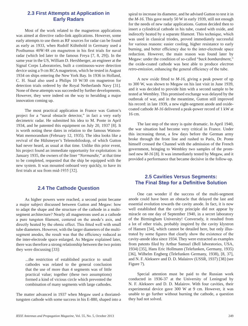
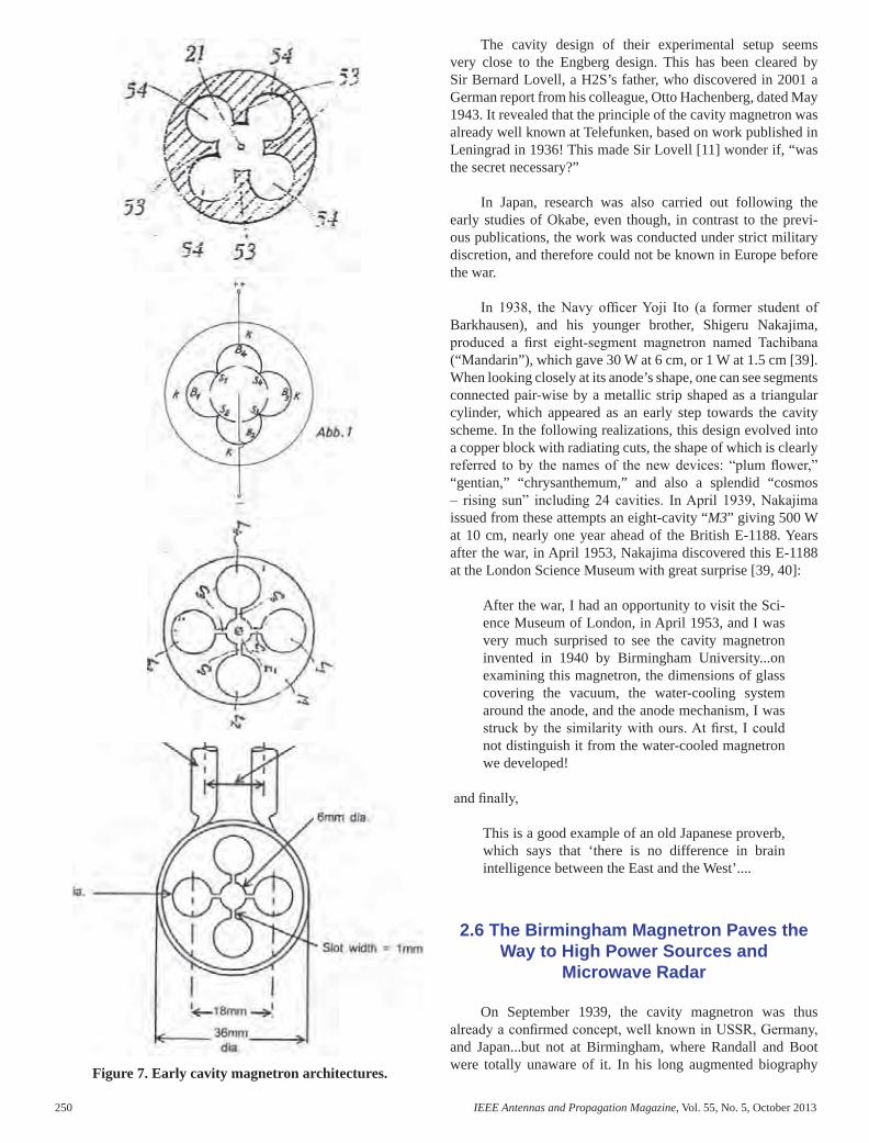
Figure 7. Early cavity magnetron architectures.
The cavity design of their experimental setup seems very close to the Engberg design. This has been cleared by Sir Bernard Lovell, a H2S’s father, who discovered in 2001 a German report from his colleague, Otto Hachenberg, dated May 1943. It revealed that the principle of the cavity magne tron was already well known at Telefunken, based on work published in Leningrad in 1936! This made Sir Lovell [11] wonder if, “was the secret necessary?”
In Japan, research was also carried out following the early studies of Okabe, even though, in contrast to the previ-ous publications, the work was conducted under strict military discretion, and therefore could not be known in Europe before the war.
In 1938, the Navy offi cer Yoji Ito (a former student of Barkhausen), and his younger brother, Shigeru Nakajima, pro duced a fi rst eight-segment magnetron named Tachibana (“Mandarin”), which gave 30 W at 6 cm, or 1 W at 1.5 cm [39]. When looking closely at its anode’s shape, one can see segments connected pair-wise by a metallic strip shaped as a triangular cylinder, which appeared as an early step towards the cavity scheme. In the following realizations, this design evolved into a copper block with radiating cuts, the shape of which is clearly referred to by the names of the new devices: “plum fl ower,” “gentian,” “chrysanthemum,” and also a splendid “cosmos – rising sun” including 24 cavities. In April 1939, Nakajima issued from these attempts an eight-cavity “M3” giving 500 W at 10 cm, nearly one year ahead of the British E-1188. Years after the war, in April 1953, Nakajima discovered this E-1188 at the London Science Museum with great surprise [39, 40]:
After the war, I had an opportunity to visit the Sci-ence Museum of London, in April 1953, and I was very much surprised to see the cavity magnetron invented in 1940 by Birmingham University...on examining this magnetron, the dimensions of glass covering the vacuum, the water-cooling system around the anode, and the anode mechanism, I was struck by the similarity with ours. At fi rst, I could not distinguish it from the water-cooled magnetron we developed!
and fi nally,
This is a good example of an old Japanese proverb, which says that ‘there is no difference in brain intelligence between the East and the West’....
2.6 The Birmingham Magnetron Paves the Way to High Power Sources and
Microwave Radar
On September 1939, the cavity magnetron was thus already a confi rmed concept, well known in USSR, Germany, and Japan...but not at Birmingham, where Randall and Boot were totally unaware of it. In his long augmented biography
of Randall, M. H. F. Wilkins refutes any polemic about that [10]. Indeed, knowing where they found their inspiration does not really matter: the credit to them is that they aimed at a specifi c objective (as simply expressed by Prof. M. Oliphant, “a microwave source giving one kilowatt on a ten centimeters wavelength”) to satisfy an urgent need (a centimetric airborne radar that would save the Londoners from the daily fright of the Blitz), and that, in a very short time, they gave to this demand a right and very effi cient solution.
The fi rst test of the cavity anode of Randall and Boot proved immediately to be very promising. On February 21, 1940, a six-cavity prototype gave 400 W at 9.9 cm, with an estimated effi ciency between 10% and 15%, nearly half of their specifi ed objective, and close to the previous results obtained by Megaw and Gutton after more than fi ve years of continuous improvements. Absolute secrecy was immediately compelled on their work, and shared with the GEC team, which was asked to develop a true industrial device based on the Birmingham prototype (see Figure 8).
The last step was still to be made. It is worth underlining the decisive part played there by E. C. S. Megaw, as the fi nal architect of a device that had to become a major innovation of the radar story. The role he had played for more than ten years as organizer of scientifi c European exchanges, enforced by his own experience, and combined with a deep knowledge of the military requirements originating from his position in GEC, had put him in the best situation to set up the cornerstone of the magnetron edifi ce. The task was led very quickly to its successful completion. The prototype of Randall and Boot used waxed seals, as facilities to manufacture sealed-off tubes were not available in Birmingham, and it was operated in a continuous-wave mode. After being introduced to the secret in April 1940, Megaw understood and immediately planned an improved six-cavity model with a sealed-off vacuum housing, an electromagnet weighting less than 50 pounds, and a working pulse mode. This E-1188 (Figure 9) was completed on May 16, giving a performance similar to that of the Birmingham model. It was quickly followed by a new E-1189 (serial No. 1: Figure 10), designed on May 25 for use in an AI airborne radar. This combined a compact sealed-off all-metal and air-cooled housing, a reduced axial dimension allowing the use of a minimum air gap for the magnet, and an enlarged thoriated-tungsten spiral cathode. First operated on June 29, it gave an output of 3 kW with a 1000 oersted permanent magnet. How ever, when it was challenged for higher 5 kW to 10 kW power, it still suffered from a reduced lifespan, due to a fast evaporation of the directly heated spiral fi lament.
We know that the question had been solved by H. Gutton with the oxide-coated cathode used for the M16, and revealed at Wembley by Dr. Ponte himself on May 6. As explained later by Megaw, the result was due mainly to the secondary electron back-bombardment, which made the power output almost independent of the heater voltage. During his visit, Ponte was kept away from the cavity secret, but he left to Megaw very
valuable information that arrived just in time to be incorporated into a new device. In the E-1189 (serial No. 2), an oxide-coated cylinder with a 0.45 cm diameter took the place of the spiral fi lament. This turned out to be the deci sive improvement: bringing together the principles of the cav ity anode and the oxide-coated cathode, the E-1189-b tested on June 26 gave a still-increased peak power of 15 kW, with a satisfying lifespan, which exceeded all expectations.
When this E-1189 was disclosed to the US allies in Sep-tember 1940 by the Tizard mission, it is fair to say that Ameri-can experts were stupefi ed by its performance. Immediately integrated in the gigantic war effort of the US industry, the cavity magnetron became the heart of more than 150 new radars of all categories designed between 1941 and 1944. This gave to the allied armies a decisive advantage, which changed the course of WWII.
Figure 8. The RandallBoot fi rst prototype.
Figure 9. Magnetron Type E-1188 (GEC, May 16).
Figure 10. Magnetron E-1189 serial No. 1 (GEC, June 29).
AP_Mag_Oct_2013_Final.indd 250 12/15/2013 3:55:14 PM

IEEE Antennas and Propagation Magazine, Vol. 55, No. 5, October 2013 251
Figure 7. Early cavity magnetron architectures.
The cavity design of their experimental setup seems very close to the Engberg design. This has been cleared by Sir Bernard Lovell, a H2S’s father, who discovered in 2001 a German report from his colleague, Otto Hachenberg, dated May 1943. It revealed that the principle of the cavity magne tron was already well known at Telefunken, based on work published in Leningrad in 1936! This made Sir Lovell [11] wonder if, “was the secret necessary?”
In Japan, research was also carried out following the early studies of Okabe, even though, in contrast to the previ-ous publications, the work was conducted under strict military discretion, and therefore could not be known in Europe before the war.
In 1938, the Navy offi cer Yoji Ito (a former student of Barkhausen), and his younger brother, Shigeru Nakajima, pro duced a fi rst eight-segment magnetron named Tachibana (“Mandarin”), which gave 30 W at 6 cm, or 1 W at 1.5 cm [39]. When looking closely at its anode’s shape, one can see segments connected pair-wise by a metallic strip shaped as a triangular cylinder, which appeared as an early step towards the cavity scheme. In the following realizations, this design evolved into a copper block with radiating cuts, the shape of which is clearly referred to by the names of the new devices: “plum fl ower,” “gentian,” “chrysanthemum,” and also a splendid “cosmos – rising sun” including 24 cavities. In April 1939, Nakajima issued from these attempts an eight-cavity “M3” giving 500 W at 10 cm, nearly one year ahead of the British E-1188. Years after the war, in April 1953, Nakajima discovered this E-1188 at the London Science Museum with great surprise [39, 40]:
After the war, I had an opportunity to visit the Sci-ence Museum of London, in April 1953, and I was very much surprised to see the cavity magnetron invented in 1940 by Birmingham University...on examining this magnetron, the dimensions of glass covering the vacuum, the water-cooling system around the anode, and the anode mechanism, I was struck by the similarity with ours. At fi rst, I could not distinguish it from the water-cooled magnetron we developed!
and fi nally,
This is a good example of an old Japanese proverb, which says that ‘there is no difference in brain intelligence between the East and the West’....
2.6 The Birmingham Magnetron Paves the Way to High Power Sources and
Microwave Radar
On September 1939, the cavity magnetron was thus already a confi rmed concept, well known in USSR, Germany, and Japan...but not at Birmingham, where Randall and Boot were totally unaware of it. In his long augmented biography
of Randall, M. H. F. Wilkins refutes any polemic about that [10]. Indeed, knowing where they found their inspiration does not really matter: the credit to them is that they aimed at a specifi c objective (as simply expressed by Prof. M. Oliphant, “a microwave source giving one kilowatt on a ten centimeters wavelength”) to satisfy an urgent need (a centimetric airborne radar that would save the Londoners from the daily fright of the Blitz), and that, in a very short time, they gave to this demand a right and very effi cient solution.
The fi rst test of the cavity anode of Randall and Boot proved immediately to be very promising. On February 21, 1940, a six-cavity prototype gave 400 W at 9.9 cm, with an estimated effi ciency between 10% and 15%, nearly half of their specifi ed objective, and close to the previous results obtained by Megaw and Gutton after more than fi ve years of continuous improvements. Absolute secrecy was immediately compelled on their work, and shared with the GEC team, which was asked to develop a true industrial device based on the Birmingham prototype (see Figure 8).
The last step was still to be made. It is worth underlining the decisive part played there by E. C. S. Megaw, as the fi nal architect of a device that had to become a major innovation of the radar story. The role he had played for more than ten years as organizer of scientifi c European exchanges, enforced by his own experience, and combined with a deep knowledge of the military requirements originating from his position in GEC, had put him in the best situation to set up the cornerstone of the magnetron edifi ce. The task was led very quickly to its successful completion. The prototype of Randall and Boot used waxed seals, as facilities to manufacture sealed-off tubes were not available in Birmingham, and it was operated in a continuous-wave mode. After being introduced to the secret in April 1940, Megaw understood and immediately planned an improved six-cavity model with a sealed-off vacuum housing, an electromagnet weighting less than 50 pounds, and a working pulse mode. This E-1188 (Figure 9) was completed on May 16, giving a performance similar to that of the Birmingham model. It was quickly followed by a new E-1189 (serial No. 1: Figure 10), designed on May 25 for use in an AI airborne radar. This combined a compact sealed-off all-metal and air-cooled housing, a reduced axial dimension allowing the use of a minimum air gap for the magnet, and an enlarged thoriated-tungsten spiral cathode. First operated on June 29, it gave an output of 3 kW with a 1000 oersted permanent magnet. How ever, when it was challenged for higher 5 kW to 10 kW power, it still suffered from a reduced lifespan, due to a fast evaporation of the directly heated spiral fi lament.
We know that the question had been solved by H. Gutton with the oxide-coated cathode used for the M16, and revealed at Wembley by Dr. Ponte himself on May 6. As explained later by Megaw, the result was due mainly to the secondary electron back-bombardment, which made the power output almost independent of the heater voltage. During his visit, Ponte was kept away from the cavity secret, but he left to Megaw very
valuable information that arrived just in time to be incorporated into a new device. In the E-1189 (serial No. 2), an oxide-coated cylinder with a 0.45 cm diameter took the place of the spiral fi lament. This turned out to be the deci sive improvement: bringing together the principles of the cav ity anode and the oxide-coated cathode, the E-1189-b tested on June 26 gave a still-increased peak power of 15 kW, with a satisfying lifespan, which exceeded all expectations.
When this E-1189 was disclosed to the US allies in Sep-tember 1940 by the Tizard mission, it is fair to say that Ameri-can experts were stupefi ed by its performance. Immediately integrated in the gigantic war effort of the US industry, the cavity magnetron became the heart of more than 150 new radars of all categories designed between 1941 and 1944. This gave to the allied armies a decisive advantage, which changed the course of WWII.
Figure 8. The RandallBoot fi rst prototype.
Figure 9. Magnetron Type E-1188 (GEC, May 16).
Figure 10. Magnetron E-1189 serial No. 1 (GEC, June 29).
AP_Mag_Oct_2013_Final.indd 251 12/15/2013 3:55:14 PM

252 IEEE Antennas and Propagation Magazine, Vol. 55, No. 5, October 2013
3. Concluding Remarks
Like many other disruptive breakthroughs, the cavity magnetron was the result of a number of related explorations, in technology, in experiment, and in theory. Many other sci-entists, scattered over quite a few countries, made signifi cant advances. However, exchange of ideas and opinions in scien-tifi c forums was getting more and more diffi cult in the build-up for WW II, as well as between Eastern and Western scien tists in the ensuing “Cold War” period. The actual global status of science and technology was known in a rather frag mented way to many engineers and scientists. The military relevance at the time led to teams working on the same type of problem, but in imposed isolation. Although the Birmingham team had brilliant ideas and their share in the development proved decisive, it is fair to say that without the contributions from others, their degree of success and the pace of the pro gress would not have been so great, or maybe it would have been too late for a timely development of microwave high-power radar in World War II.
4. References
1. E. G. Bowen, Radar Days, Briston, UK, Adam Hilger (Institute of Physics Publishing), 1987.
2. L. W. Alvarez, Adventures of a Physicist, New York, Basic Books, 1987.
3. B. Lovell, Echoes of War, Bristol, Adam Hilger, 1991.
4. D. E. Fisher, A Summer Bright and Terrible: Winston Churchill, Lord Dowding, Radar, and the Impossible Triumph of the Battle of Britain, Berkeley, CA, Counterpoint Press, 2005.
5. D. Zimmermann, Top Secret Exchange: the Tizard Mission and the Scientifi c War, Montreal, McGill Queen’s University Press, 1996.
6. P. A. Redhead, “The Invention of the Cavity Magnetron and its Introduction Into Canada and the U.S.A.,” La Physique au Canada, Novembre-Décembre 2001, pp. 321-328, linked as “Complement F” of [7].
7. G. Galati, Cent’anni di radar – Ricerca, sviluppi, persone, eventi [One Hundred Years of Radar – Research, Develop ments, Persons, Events], Rome, Aracne Editrice, 2012 (in Italian).
8. Y. Blanchard, Le radar, 19042004: histoire d’un siècle d’innovations techniques et opérationnelles [The Radar 1904 – 2004: History of One Century of Technical and Operational Innovations], Paris, Ellipses, 2004 (in French).
9. R. C. Watson, Jr., Radar Origins Worldwide, Bloomington, IN, Trafford Publishing, 2009.
10. M. H. F. Wilkins, “John Turton Randall (23 March 1905 – 16 June 1984),” Biographical Memoirs of Fellows of the Royal Society, 33, 1987, pp. 493-535.
11. B. Lovell, “The Cavity Magnetron in World War II: Was the Secrecy Justifi ed?,” Notes and Records of the Royal Soci ety of London, 58, 3, 2004, pp. 283-294.
12. S. Phelps, The Tizard Mission: The Top Secret Operation that Changed the Course of World War II, Yardley, PA, Westholme Publishing, 2010.
13. Proceedings of the International Conference CAVMAG 2010 on 70 years of Cavity Magnetron, Bournemouth Univer sity, U.K., 19-20 April 2010, available online: http://academic.research.microsoft.com/Conference/4631/cavmag-international-conference-on-the-origins-and-evolution-of-the-cavity-magnetron, http://ieeexplore.ieee.org/xpl/mostRecentIssue.jsp?punumber=5557902.
14. R. L. Wathen, “Genesis of a Generator – The Early His tory of the Magnetron,” Journal of the Franklin Institute, 255, 4, 1953, pp. 271-287.
15. J. E. Brittain, “The Magnetron and the Beginnings of the Microwave Age,” Physics Today, 38, 1985, pp. 60-67.
16. H. E. Guerlac, “The Early History of Microwaves,” in Radar in World War II, The History of Modern Physics 1800-1950 series, American Institute of Physics, New York, Tomash Publishers, 1987, Chapter 8, pp. 185-240.
17. E. B. Callick, Meters to Microwaves, British Development of Active Components for Radar Systems, 1937 to 1944, IEE History of Technology series 11, Stevenage, UK, Peter Pelegrinus Ltd., 1990.
18. A. W. Hull, “The Effect of a Uniform Magnetic Field on the Motion of Electrons Between Coaxial Cylinders,” Physical Review, 18, 1, 1921, pp. 31-57 .
19. A. Žáček – “Magnetron Generators,” Slaboproudy obzor [Journal of Czechoslovak Radio Engineers], 1, 1, pp. 6-9 and 1, 2, pp. 22-26, 1936 (in Czech).
20. A. Žáček – “Nová metoda k vytvorení netlumenych oscilací [New Method of Generating Undamped Oscilla tions],” Časopis pro pěstování matematiky a fysiky [Journal for the Cultivation of Mathematics and Physics], 53, 1924, pp. 378-380 (in Czech).
21. L. Mergl – “Magnetron – Its Origin and the Contribution of August Žáček to its Development,” in DVT dejiny ved a techniky [History of Sciences and Technology], XXXI, Prague, Society for the History of Sciences and Technology, 1998.
22. E. Habann, “Eine neue Generatorröhre [A New Generator Tube]” Zeitschrift für Hochfrequenztechnik, 24, 1924, pp. 115-120 and 135-141 (in German).
23. E. Habann, Die neuere Entwicklung der Hochfrequenztelephonie und telegraphie auf Leitungen [Recent Developments of Wired High Frequency Telephony and Telegraphy], Braunschweig, Germany, Vieweg & Sohn, 1929.
24. H. Yagi, “Beam Transmission of Ultra Short Waves,” Proceedings of the IRE, 16, 6, 1928, pp. 715- 740.
[25. M. Ponte, “Sur l’emploi des champs magnétiques pour la production des ondes ultracourtes [On the Usage of Magnetic Fields in Microwave Generation],” in Vingtcinq années de T.S.F. [TwentyFive Years of T.S.F.], Paris, SFR ed. Makowsky, 1935, pp. 183-198. 26. K. Posthumus, “Oscillations in a Split Anode Magnetron,” The Wireless Engineer, 12, 1935, pp. 126-132.
27. K. Postumus and E. C. S. Megaw, “Magnetron Oscilla-tions,” Nature, 135, 3422, 1935, pp. 914-914.
28. M. Leconte, “Statistical Study of Magnetron Patents in the Early Year of Electronics Between 1920 and 1945,” Proceed-ings of CAVMAG 2010, International Conference on the Ori-gins and Evolution of the Cavity Magnetron, Bournemouth, UK, April 19-20, 2010, pp. 11-16.
29. F. Trenkle “Die deutschen Funkmessverfahren bis 1945 [The German Radio Measurement Techniques Until 1945],” Huthing, DE, 1986.30. H. Gutton and S. Berline, “Research on the Magnetrons: S.F.R. Ultra Short Waves Magnetrons,” Bulletin de la Société Française RadioElectrique, 12ème année, 2, 1938, pp. 30-46.
31. F. O. J. Bremer and P. van Genderen (eds.), Radar Developments in the Netherlands, Thales Hengelo, NL, 2004.
32. Elie, Henri Gutton, Hugon, Ponte, “Détection d’obstacles à la navigation sans visibilité [Detection of obstacles in blind navigation],” Bulletin de la Société Française des Electriciens, 5ème série tome IX, 100, 1939, pp. 345-353. 33. E. C. S. Megaw, “The High-Power Pulsed Magnetron: A Review of Early Developments,” Journal of IEE, 93, 5, part III A, 1946, pp. 977-984.
34. W. W. Hansen, High Effi ciency Resonant Circuit, US Pat-ent No. 2,190,712 (applied July 27, 1936; granted February 20, 1940).
35. A. Samuel Electron Discharge Device, US Patent No. US2063342A (applied December 8, 1934; granted December 8, 1936).
36. H. E. Hollmann, Magnetron, US Patent No. US2123728A (applied November 29, 1935; granted July 12, 1938).
37. W. Engberg, “Schlitzanodenmagnetronroehre fuer ultra-kurze Wellen [Slot anode magnetron tube for ultra short waves]” German Patent No. 938 196 (applied November 14, 1938; published in France on July 1, 1943, and in Germany on January 1, 1956).
38. N. F. Alekseev and D. D. Malairov, “Generation of High-Power Oscillations with Magnetron in the Centimetric Band,” Proceedings of the IRE, 32, 3, March 1944, pp. 136-139.
39. S. Nakajima, “The History of Japanese Radar Develop ment to 1945,” Proc. of IEE 85 Seminar on the History of Radar IEE 85, 10-12 June 1985, London, UK, edited by IEE - London, Peter Pelegrinus Ltd., London, 1988, Chapter 18, pp. 243-258.
40. S. Nakajima “Shigeru Nnakajima, An Interview Con ducted by William Aspray (May 26, 1994),” Part of the Japa nese Oral Histories Collection, Center for the History of Elec trical Engineering, IEEE and The State University of New Jersey, 1994.
Introducing the Authors
Yves Blanchard was born in 1942, is a consulting engi-neer. He graduated from ISEN Lille in 1966. He has been a research engineer in sonar and radar for 25 years, fi rst with the French National Centre for Aerospace Studies and Research (ONERA), and later in industry with Thales, where he ended as Technical Director of the Missile Electronic unit of Thales Airborne Systems. He is also a well-known researcher into the history of radar, and has given nearly 40 papers and confer-ences on the subject. He is the author of a general history of radar developments, acknowledged in France as a referring book: Le Radar 19042004, Histoire d’un Siècle d’Innovations Techniques et Opérationnelles [The Radar 1904-2004: History of One Century of Technical and Operational Innovations] (Paris, Ellipses ed., 2004).
AP_Mag_Oct_2013_Final.indd 252 12/15/2013 3:55:14 PM

IEEE Antennas and Propagation Magazine, Vol. 55, No. 5, October 2013 253
3. Concluding Remarks
Like many other disruptive breakthroughs, the cavity magnetron was the result of a number of related explorations, in technology, in experiment, and in theory. Many other sci-entists, scattered over quite a few countries, made signifi cant advances. However, exchange of ideas and opinions in scien-tifi c forums was getting more and more diffi cult in the build-up for WW II, as well as between Eastern and Western scien tists in the ensuing “Cold War” period. The actual global status of science and technology was known in a rather frag mented way to many engineers and scientists. The military relevance at the time led to teams working on the same type of problem, but in imposed isolation. Although the Birmingham team had brilliant ideas and their share in the development proved decisive, it is fair to say that without the contributions from others, their degree of success and the pace of the pro gress would not have been so great, or maybe it would have been too late for a timely development of microwave high-power radar in World War II.
4. References
1. E. G. Bowen, Radar Days, Briston, UK, Adam Hilger (Institute of Physics Publishing), 1987.
2. L. W. Alvarez, Adventures of a Physicist, New York, Basic Books, 1987.
3. B. Lovell, Echoes of War, Bristol, Adam Hilger, 1991.
4. D. E. Fisher, A Summer Bright and Terrible: Winston Churchill, Lord Dowding, Radar, and the Impossible Triumph of the Battle of Britain, Berkeley, CA, Counterpoint Press, 2005.
5. D. Zimmermann, Top Secret Exchange: the Tizard Mission and the Scientifi c War, Montreal, McGill Queen’s University Press, 1996.
6. P. A. Redhead, “The Invention of the Cavity Magnetron and its Introduction Into Canada and the U.S.A.,” La Physique au Canada, Novembre-Décembre 2001, pp. 321-328, linked as “Complement F” of [7].
7. G. Galati, Cent’anni di radar – Ricerca, sviluppi, persone, eventi [One Hundred Years of Radar – Research, Develop ments, Persons, Events], Rome, Aracne Editrice, 2012 (in Italian).
8. Y. Blanchard, Le radar, 19042004: histoire d’un siècle d’innovations techniques et opérationnelles [The Radar 1904 – 2004: History of One Century of Technical and Operational Innovations], Paris, Ellipses, 2004 (in French).
9. R. C. Watson, Jr., Radar Origins Worldwide, Bloomington, IN, Trafford Publishing, 2009.
10. M. H. F. Wilkins, “John Turton Randall (23 March 1905 – 16 June 1984),” Biographical Memoirs of Fellows of the Royal Society, 33, 1987, pp. 493-535.
11. B. Lovell, “The Cavity Magnetron in World War II: Was the Secrecy Justifi ed?,” Notes and Records of the Royal Soci ety of London, 58, 3, 2004, pp. 283-294.
12. S. Phelps, The Tizard Mission: The Top Secret Operation that Changed the Course of World War II, Yardley, PA, Westholme Publishing, 2010.
13. Proceedings of the International Conference CAVMAG 2010 on 70 years of Cavity Magnetron, Bournemouth Univer sity, U.K., 19-20 April 2010, available online: http://academic.research.microsoft.com/Conference/4631/cavmag-international-conference-on-the-origins-and-evolution-of-the-cavity-magnetron, http://ieeexplore.ieee.org/xpl/mostRecentIssue.jsp?punumber=5557902.
14. R. L. Wathen, “Genesis of a Generator – The Early His tory of the Magnetron,” Journal of the Franklin Institute, 255, 4, 1953, pp. 271-287.
15. J. E. Brittain, “The Magnetron and the Beginnings of the Microwave Age,” Physics Today, 38, 1985, pp. 60-67.
16. H. E. Guerlac, “The Early History of Microwaves,” in Radar in World War II, The History of Modern Physics 1800-1950 series, American Institute of Physics, New York, Tomash Publishers, 1987, Chapter 8, pp. 185-240.
17. E. B. Callick, Meters to Microwaves, British Development of Active Components for Radar Systems, 1937 to 1944, IEE History of Technology series 11, Stevenage, UK, Peter Pelegrinus Ltd., 1990.
18. A. W. Hull, “The Effect of a Uniform Magnetic Field on the Motion of Electrons Between Coaxial Cylinders,” Physical Review, 18, 1, 1921, pp. 31-57 .
19. A. Žáček – “Magnetron Generators,” Slaboproudy obzor [Journal of Czechoslovak Radio Engineers], 1, 1, pp. 6-9 and 1, 2, pp. 22-26, 1936 (in Czech).
20. A. Žáček – “Nová metoda k vytvorení netlumenych oscilací [New Method of Generating Undamped Oscilla tions],” Časopis pro pěstování matematiky a fysiky [Journal for the Cultivation of Mathematics and Physics], 53, 1924, pp. 378-380 (in Czech).
21. L. Mergl – “Magnetron – Its Origin and the Contribution of August Žáček to its Development,” in DVT dejiny ved a techniky [History of Sciences and Technology], XXXI, Prague, Society for the History of Sciences and Technology, 1998.
22. E. Habann, “Eine neue Generatorröhre [A New Generator Tube]” Zeitschrift für Hochfrequenztechnik, 24, 1924, pp. 115-120 and 135-141 (in German).
23. E. Habann, Die neuere Entwicklung der Hochfrequenztelephonie und telegraphie auf Leitungen [Recent Developments of Wired High Frequency Telephony and Telegraphy], Braunschweig, Germany, Vieweg & Sohn, 1929.
24. H. Yagi, “Beam Transmission of Ultra Short Waves,” Proceedings of the IRE, 16, 6, 1928, pp. 715- 740.
[25. M. Ponte, “Sur l’emploi des champs magnétiques pour la production des ondes ultracourtes [On the Usage of Magnetic Fields in Microwave Generation],” in Vingtcinq années de T.S.F. [TwentyFive Years of T.S.F.], Paris, SFR ed. Makowsky, 1935, pp. 183-198. 26. K. Posthumus, “Oscillations in a Split Anode Magnetron,” The Wireless Engineer, 12, 1935, pp. 126-132.
27. K. Postumus and E. C. S. Megaw, “Magnetron Oscilla-tions,” Nature, 135, 3422, 1935, pp. 914-914.
28. M. Leconte, “Statistical Study of Magnetron Patents in the Early Year of Electronics Between 1920 and 1945,” Proceed-ings of CAVMAG 2010, International Conference on the Ori-gins and Evolution of the Cavity Magnetron, Bournemouth, UK, April 19-20, 2010, pp. 11-16.
29. F. Trenkle “Die deutschen Funkmessverfahren bis 1945 [The German Radio Measurement Techniques Until 1945],” Huthing, DE, 1986.30. H. Gutton and S. Berline, “Research on the Magnetrons: S.F.R. Ultra Short Waves Magnetrons,” Bulletin de la Société Française RadioElectrique, 12ème année, 2, 1938, pp. 30-46.
31. F. O. J. Bremer and P. van Genderen (eds.), Radar Developments in the Netherlands, Thales Hengelo, NL, 2004.
32. Elie, Henri Gutton, Hugon, Ponte, “Détection d’obstacles à la navigation sans visibilité [Detection of obstacles in blind navigation],” Bulletin de la Société Française des Electriciens, 5ème série tome IX, 100, 1939, pp. 345-353. 33. E. C. S. Megaw, “The High-Power Pulsed Magnetron: A Review of Early Developments,” Journal of IEE, 93, 5, part III A, 1946, pp. 977-984.
34. W. W. Hansen, High Effi ciency Resonant Circuit, US Pat-ent No. 2,190,712 (applied July 27, 1936; granted February 20, 1940).
35. A. Samuel Electron Discharge Device, US Patent No. US2063342A (applied December 8, 1934; granted December 8, 1936).
36. H. E. Hollmann, Magnetron, US Patent No. US2123728A (applied November 29, 1935; granted July 12, 1938).
37. W. Engberg, “Schlitzanodenmagnetronroehre fuer ultra-kurze Wellen [Slot anode magnetron tube for ultra short waves]” German Patent No. 938 196 (applied November 14, 1938; published in France on July 1, 1943, and in Germany on January 1, 1956).
38. N. F. Alekseev and D. D. Malairov, “Generation of High-Power Oscillations with Magnetron in the Centimetric Band,” Proceedings of the IRE, 32, 3, March 1944, pp. 136-139.
39. S. Nakajima, “The History of Japanese Radar Develop ment to 1945,” Proc. of IEE 85 Seminar on the History of Radar IEE 85, 10-12 June 1985, London, UK, edited by IEE - London, Peter Pelegrinus Ltd., London, 1988, Chapter 18, pp. 243-258.
40. S. Nakajima “Shigeru Nnakajima, An Interview Con ducted by William Aspray (May 26, 1994),” Part of the Japa nese Oral Histories Collection, Center for the History of Elec trical Engineering, IEEE and The State University of New Jersey, 1994.
Introducing the Authors
Yves Blanchard was born in 1942, is a consulting engi-neer. He graduated from ISEN Lille in 1966. He has been a research engineer in sonar and radar for 25 years, fi rst with the French National Centre for Aerospace Studies and Research (ONERA), and later in industry with Thales, where he ended as Technical Director of the Missile Electronic unit of Thales Airborne Systems. He is also a well-known researcher into the history of radar, and has given nearly 40 papers and confer-ences on the subject. He is the author of a general history of radar developments, acknowledged in France as a referring book: Le Radar 19042004, Histoire d’un Siècle d’Innovations Techniques et Opérationnelles [The Radar 1904-2004: History of One Century of Technical and Operational Innovations] (Paris, Ellipses ed., 2004).
AP_Mag_Oct_2013_Final.indd 253 12/15/2013 3:55:15 PM

254 IEEE Antennas and Propagation Magazine, Vol. 55, No. 5, October 2013
Gaspare Galati was born in 1946. He has been an active researcher in radar systems since the early 1970s. He started with the company Selenia, where from 1984 to 1986 he headed the System Analysis Group of the Research Depart-ment. Presently, he is a full professor of Radiolocation at the Tor Vergata University of Rome, where he also teaches prob-ability, statistics, and random processes. His main interests are in radar theory and techniques, detection and estimation, navi gation and air traffi c management, and recently, the history of Italian radar. This is treated in his book Cent’anni di Radar – Ricerca, Sviluppi, Persone, Eventi [One Hundred Years Of Radar – Research, Developments, Persons, Events],” (Rome, Aracne Editrice, 2012).
Piet Van Genderen was born in 1947. He graduated from the University of Twente in Enschede in 1971. He worked with the National Aerospace Laboratory in Amster dam until 1979. He then moved to Hollandse Signaalapparaten, now Thales Nederland, where he held sev eral positions in R&D. In 1994, he was also appointed a full professor at the Delft University of Technology. He holds an honorary doctorate of the MTA of Bucharest, Romania. His main research interests are in the design of waveforms and associated algorithms for extracting object features. He is editor of the book Radar Developments in The Netherlands (2004).
AP_Mag_Oct_2013_Final.indd 254 12/15/2013 3:55:15 PM