7. subject details 7.5 microwave engineering · characteristic equation and cut-off frequencies,...
TRANSCRIPT
7. SUBJECT DETAILS
7.5 MICROWAVE ENGINEERING
7.5.1 Objective and Relevance
7.5.2 Scope
7.5.3 Prerequisites
7.5.4 Syllabus
i. JNTU
ii. GATE
iii. IES
7.5.5 Suggested Books
7.5.6 Websites
7.5.7 Experts’ Details
7.5.8 Journals
7.5.9 Findings and Developments
7.5.10 Session Plan
7.5.11 Student Seminar Topics
7.5.12 Question Bank
i. JNTU
ii. GATE
iii. IES
7.5.1 OBJECTIVE AND RELEVANCE
The central theme of this subject concerns with the basic principles and applications of microwave devices
and circuits. As microwaves behave more like rays of light than the ordinary radio waves, this unique
behaviour of microwaves leads to a broad range of applications in modern technology. The diverse
applications of these microwaves are radio astronomy, long distance communication, space navigation,
radar system, medical equipment and missile electronic systems.
As a result of the rapid rate of growth of microwave technology in research and industry, there is need for
electronic engineers to understand and study the theoritical and experimental design and analysis of
microwave devices and circuits.
7.5.2 SCOPE
Microwave Engineering is the study of centimeter and millimeter waves. Division of total frequency is
made by different standards. The tube version microwave amplifiers and oscillators, like klystron,
magnetron, TWT etc., are studied quantitatively and are compared on the basis of power and efficiency.
Low-power solid state microwave devices that can be used for amplification and generation like Gunn
diode, Avalanche diodes etc., are studied in detail. In addition, different components used in microwave
systems like wave guides, tee junctions, directional couplers etc., are studied and their scattering matrices
are derived. Measurement techniques for gain, radiation patterns, SWR are also covered at the end.
7.5.3 PRE-REQUISITES
Knowledge of Electromagnetic theory and transmission line theory
7.5.4.1 SYLLABUS - JNTU
UNIT - I
MICROWAVE TRANSMISSIONLINES [1]
OBJECTIVE This unit provides microwave frequency bands, applications of microwaves and microwave transmission
lines(wave guides),types of wave guides ,analysis of Rectangular wave guides ,propagation of EM waves
in different modes and power handling capabilities of wave guides
SYLLABUS
Introduction, Microwave Spectrum and Bands, Applications of Microwaves. Rectangular Waveguides-
Solution of wave equation in rectangular wave guides, TE/TM mode analysis, Expressions for Fields,
Characteristic Equation and Cut-off frequencies, Filter characteristics, Dominant and degenerate modes,
Sketches of TE and TM mode fields in the cross-section, Mode characteristics-Phase and Group
Velocities, Wavelengths and impedance relations; Related problems.
UNIT - II
MICROWAVE TRANSMISSIONLINES [2]
OBJECTIVE
This unit deals with circular waveguide analysis, mode characteristics .microstrip lines, rectangular and
cylindricaL cavities, modes and resonant frequencies of cavity resonators
SYLLABUS
Rectangular guides: Power transmission and Power losses, Impossibility of TEM mode.
Microstrip Lines [1]--Introduction, Z Relations, Effective Dielectric constant, Losses, Q factor. Cavity
Resonators [1]-Introduction, Rectangular and Cylindrical Cavities, Dominant Modes and Resonant
Frequencies Q factor and Coupling coefficients. Related problems.
UNIT - III
WAVEGUIDE COMPONENTS AND APPLICATIONS-1
OBJECTIVE This unit gives complete idea about wave guide components, hybrid circuits including the devices used for
power division or combiners, their constructional details, properties and their wide range of applications
and also components details used to connect the wave guides.
SYLLABUS
Coupling mechanisms-Probe, Loop, Aperture types, waveguide Discontinuities-Waveguide irises, Tuning
screws and Posts, Matched loads, waveguide attenuators-Resistive Cards, Rotary vane type, waveguide
phase shifters-Dielectric, Rotary Vane types. Waveguide multiport junctions-E plane and H-plane Tees,
Magic Tee, Directional couplers-2 Hole, Bethe hole types. Illustrated problems.
UNIT - IV
WAVEGUIDE COMPONENTS AND APPLICATIONS-1I
OBJECTIVE This unit deals with ferrites used in wave guides, ferrite components, and microwave guide components
analysis in terms of scattering parameters
SYLLABUS
Ferrites[3]- Composition and characteristics, Faraday Rotation; Ferrite Components Gyrator, Isolator,
Circulator, Scattering Matrix [3]-Significance, Formulation and properties, S-matrix Calculations for 2-port
junction, E plane and H plane Tees, Magic Tee, Directional coupler, Circulator and Isolator. Related
problems.
UNIT - V
MICROWAVE TUBES-I [1, 2]
OBJECTIVE
This unit provides the advantage of microwave tubes over conventional tubes, O type tubes, their
constructional details, characteristics and their applications in various fields.
SYLLABUS
Limitations and Losses of conventional tubes at microwave frequencies. Microwave tubes-O type and M
type classifications. O-type tubes: 2 Cavity Klystrons-Structure, Re-entrant cavities, Velocity Modulation
process and Applegate Diagram, Bunching Process and Small signal theory -Expressions for o/p power and
Efficiency. Reflex klystrons-Structure, Applegate Diagram and Principle of working, Mathematical Theory
of Bunching, Power Output, Efficiency, Oscillating modes and output characteristics, effect repeller
voltage on power output, illustrated problems
UNIT - VI
HELIX TWTS [1, 2]
OBJECTIVE
This unit deals with slow wave structures, TWT amplifier analysis, M-type tubes , 8-cavity cylindrical
travelling wave magnetron, principle of operation, mode operation and output characteristics.
SYLLABUS
Helix TWTS [1, 2]
Significance, Types and Characteristics of Slow Wave Structures; Structure of TWT and Amplification
Process (qualitative treatment),Suppression of Oscillations, Nature of the four Propagation Constants, gain
considerations.
M-type Tubes [1,2] Introduction, crossed field effects, Magnetrons-Different Types, 8-Cavity Cylindrical Travelling Wave
Magnetron-Hull Cut-off and Hatree Conditions, Modes of Resonance and Pi-Mode operation, Separation
of Pi-Mode, o/p characteristics.
UNIT - VII
MICROWAVE SOLID STATE DEVICES [1]
OBJECTIVE
This unit will give an explanation in depth about various types of microwave solid state devices which
operate in negative resistance region, their characteristics and applications
SYLLABUS
Introduction, Classification, Applications. TEDs-Introduction, Gunn diode-Principle, RWH Theory,
Characteristics, Basic Modes of Operation, Oscillations Modes, Avalanche Transit time Devices.
UNIT - VIII

MICROWAVE MEASUREMENTS [1]
OBJECTIVE
This unit deals with measurements of various parameters of microwaves and also gives the complete
features of the microwave bench.
SYLLABUS
Description of Microwave Bench-Different Blocks and their Features, Precautions, microwave Power
Measurement-Bolometer Method, Measurement of Attenuation, Frequency, VSWR, Cavity Q, Impedance
measurements.
7.5.4.2 GATE SYLLABUS
UNIT - I Rectangular Wave Guides
UNIT - II
Not Applicable
UNIT - III
Not Applicable
UNIT - IV
Not Applicable
UNIT - V
Not Applicable
UNIT - V
Not Applicable
UNIT - VI
Not Applicable
UNIT - V II
Not Applicable
UNIT - V III
Not Applicable
7.5.4.3 IES SYLLABUS
Microwaves tubes and solid state devices, Microwave generation and amplifiers, wave guides and other
microwave components and circuits, Microstrip circuits, Microwave measurements, Masers, Lasers,
Microwave propagation. Microwave communication systems terrestrial and satellite based.
UNIT - I
Wave guides, Micro Wave propagation
UNIT - II Resonators, Micro strip Circuits
UNIT - III Microwave components and circuits
UNIT - IV Microwave components and circuits
UNIT - V Microwave tubes and generation and amplifiers
UNIT - VI
NOT APPLICABLE
UNIT - VII
Microwaves solid state devices, Masers, Lasers
UNIT - VIII
Microwave measurements, Microwave communication systems terrestrial and satellite based.
7.5.5 SUGGESTED BOOKS
TEXT BOOKS
T1. Microwave Devices and Circuits- Samuel Y. Liao, PHI, 3rd edition, 2003
T2. Microwave Principles, Herbert J. Reich, J.G. Skalnik, P.F. Ordung and H.L. Krauss, CBS Publishers and
Distributors, New Delhi ,2004.
REFERENCE BOOKS
R1. Foundation for Microwave Engineering -R.E. Collin, IEEE Press, John Wiley,2nd Edition ,2002.
R2. Microwave Circuits and Passive Devices-M.L. Sisodiaand G.S. Raghuvanshi,Wiley Eastern Ltd, New Age
International Publishers Ltd,1995
R3 Microwave Engineering Passive Circuits-Peter A.Rizzi, PHI, 1999.
R4. Electronic and Radio engineering -F.E. terman,McGraw-hill,4th Edition, 1955.
R5. Microwave Engineering, A Das and S.K. Das, TMH, 2nd Edition, 2009
7.5.6 WEBSITES
1. www.eecs.tufts.edu
2. www.peeas.ecs.umass.edu/degee/ece_degeee.html
3. www.georgefox.edu/catlog/undergrad/enge.htmlr
4. www.eciu.org/core/smg_hamburg.php
5. www.rfcafe.com
6. www.ecs.umas.edu
7. Www. mwrf.com
8. www.eagleware.com
7.5.7 EXPERTS’ DETAILS
INTERNATIONAL 1. Prof. Madhu S.Gupta
Director of communication systems and signal processing institute
San Diego State University
email:mgupta@word_sdsu.edu
2. Dr. R.F. Schiffmann
149 wests, 88 Street
Newyork , USA-10024 2401
email:[email protected]
NATIONAL
1. Prof. R.C. Jain
JIIT, Uttarpradesh
2. Prof. Dr. Devi Chandha
IIT Delhi
3. Girish P.Saroph
Associate Professor
IIT, Bombay
email: [email protected]
REGIONAL
1. Prof. V M. Pandari Pandey
Dept. of ECE, O.U. Hyd.
email : [email protected]
2. Prof. K.S.Sharma
Dept.of ECE,
SNIST. College.
3. Prof. K.V. Srinivasa Rao,
Dept of ECE,
Aurora Engg. College.
7.5.8 JOURNALS
INTERNATIONAL
1. Microwave Jounral on IEEE
2. Microwave Magazine on IEEE
3. Microwave Theory Techniques on IEEE
4. Solid State circuits Magazine on IEEE
5. Microwave Engineering
6. Planar Microwave Engineering
7. RF and Microwave Engineering
NATIONAL
1. Technical Review on IETE
2. Telecommunication
3. Journal on Communication Technology
4. Journal of Research on IETE
5. Journal of Telecommunication
6. Microwave and antenna Engineering
7. RF and Microwave Engineering professional networks.
7.5.9 FINDINGS AND DEVELOPMENTS
1. Characterization of wave guide with combination of conductor and periodic boundary contours, application
to the analysis of by periodic structures, F.Ferranti, M.Nakhla, G. Antonini, T.Dhanene, L.knockaert &
A.E. Ruehli, IEEE Transactions on MTT, Vol.16, Page No. 419-431, March 2012.
2. Multimode coupling wave theory for helically corrigated wave guide, W.H.K. Ronald, ADR Phelps, IEEE
Transaction of MTT, Vol.60, Page No.1-8, January 2012.
3. A Circular pathc resonator for the measurement of microwave permitivity of Nematic liquid crystal, D.E.
Schaub and D.R. Oliver, IEEE Transactions on MIT, Vol.59, Page No.185-195, July 2011.
4. Comprehensive technique to determine the boradband physically consitent material characteristics of
microstrib lines, Z.Zhou & K.L Meido, IEEE Transactions on MTT Vol.58, Page No.1855-1863, January,
2010.
5. High-efficiency fast RF/Microwave power amplifiers, S. Gao from IEEE Microwave Magazine, Feb 2006,
Vol. 7, No. 1
6. Ku band MMIC phase shifter using a parallel resonator, D. W. Kang, H. D. Lee, Ch. Kim/S.Hang from
IEEE microwave magazine, Jan 2006, Vol. 54, No. 1
7. Novel batler matrix using CPW multilayer technology, Mourad Nedil, Tayeb. from IEEE MTT, Jan 2006,
Vol 54, No.1.
8. Compact wide band branch live hybrids, Y. H. Chan and J. S. Hang from IEEE MTT, Feb 2006, Vol 54,
No.2.
9. Travelling wave microwave fiber-optic link’s, H. H. Hashim and S. Iezekiel from IEEE MTT, Feb 2006
(Part-II) Vol-54, No. 2.
10. Time constant control of microwave integrators using tranmission lines, Ching-Wen Huse, Lin Chuan Tsai
from IEEE MTT, Vol. 54, No. 3, March 06.
11. Improved wide -band schiffman phase shifter, Yang-Xin Guo, Zhen-Yu Zang from IEEE MTT, Vol.54,
No. 3, March 06.
12. Broad band high efficiency circularly polarized active antenna and array for RF-front end applications, Y.
Qln, S. Gao. A. Sambell, IEEE MTT, Vol. 54, NO. 7, July-2006.
13. Micromachined rectangular-coarial TXL, J. R. Reid, E. D. Marsh and R. T. Webster from IEEE, MTT, Vol.
54, No. 7 July-2006.
14. Distortion mechanism in varactor-diode tuned microwave filter A, B.E. Carey, Smith and P. A. Warr from
IEEE, MTT, Vol. 54, No. 9, Sept.-2006.
15. Microwave Circuits Simulation Softwares
i.IE 3D Simulation Software - www.zeland.com
ii.ADS- Ansoft
iii.HF SS Simulation Solutions - www. sonnetsoftware.com
iv.Microstrip Line Simulation - www.microstriper.com
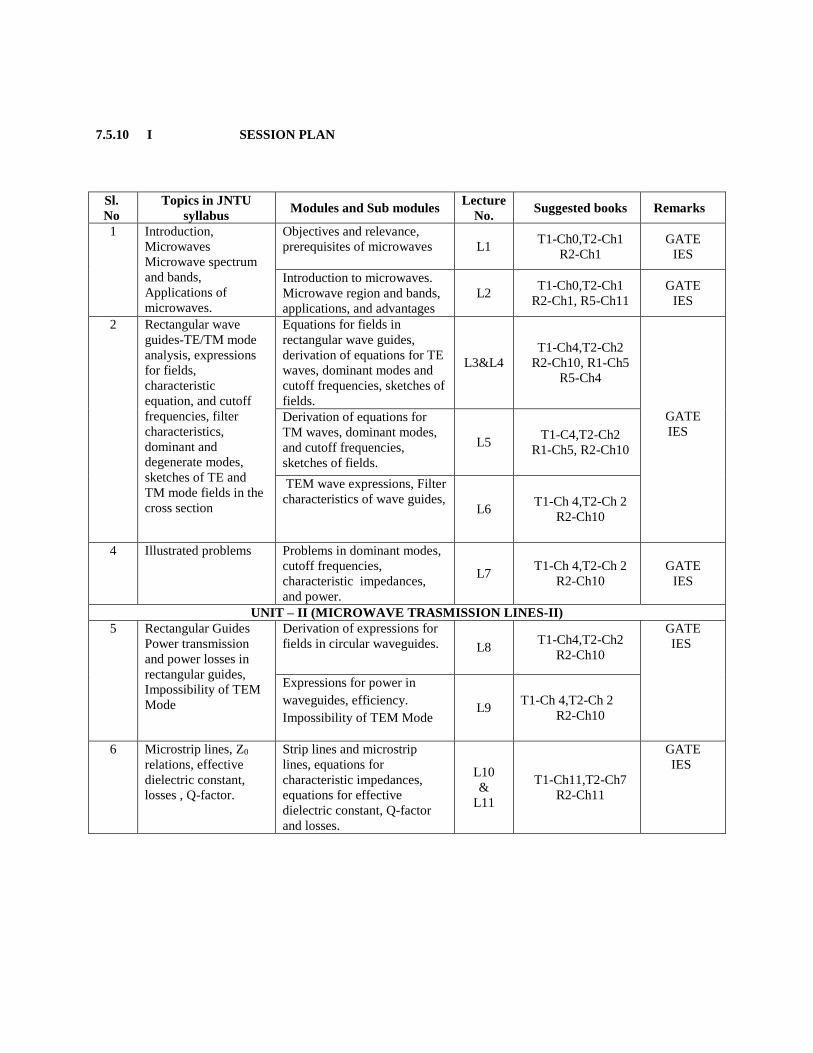
7.5.10 I SESSION PLAN
Sl.
No
Topics in JNTU
syllabus Modules and Sub modules
Lecture
No. Suggested books Remarks
1
Introduction,
Microwaves
Microwave spectrum
and bands,
Applications of
microwaves.
Objectives and relevance,
prerequisites of microwaves L1 T1-Ch0,T2-Ch1
R2-Ch1
GATE
IES
Introduction to microwaves.
Microwave region and bands,
applications, and advantages
L2 T1-Ch0,T2-Ch1
R2-Ch1, R5-Ch11
GATE
IES
2
Rectangular wave
guides-TE/TM mode
analysis, expressions
for fields,
characteristic
equation, and cutoff
frequencies, filter
characteristics,
dominant and
degenerate modes,
sketches of TE and
TM mode fields in the
cross section
Equations for fields in
rectangular wave guides,
derivation of equations for TE
waves, dominant modes and
cutoff frequencies, sketches of
fields.
L3&L4
T1-Ch4,T2-Ch2
R2-Ch10, R1-Ch5
R5-Ch4
GATE
IES Derivation of equations for
TM waves, dominant modes,
and cutoff frequencies,
sketches of fields.
L5 T1-C4,T2-Ch2
R1-Ch5, R2-Ch10
TEM wave expressions, Filter
characteristics of wave guides, L6
T1-Ch 4,T2-Ch 2
R2-Ch10
4 Illustrated problems Problems in dominant modes,
cutoff frequencies,
characteristic impedances,
and power.
L7 T1-Ch 4,T2-Ch 2
R2-Ch10
GATE
IES
UNIT – II (MICROWAVE TRASMISSION LINES-II) 5 Rectangular Guides
Power transmission
and power losses in
rectangular guides,
Impossibility of TEM
Mode
Derivation of expressions for
fields in circular waveguides. L8 T1-Ch4,T2-Ch2
R2-Ch10
GATE
IES
Expressions for power in
waveguides, efficiency.
Impossibility of TEM Mode L9
T1-Ch 4,T2-Ch 2
R2-Ch10
6 Microstrip lines, Z0
relations, effective
dielectric constant,
losses , Q-factor.
Strip lines and microstrip
lines, equations for
characteristic impedances,
equations for effective
dielectric constant, Q-factor
and losses.
L10
&
L11
T1-Ch11,T2-Ch7
R2-Ch11
GATE
IES
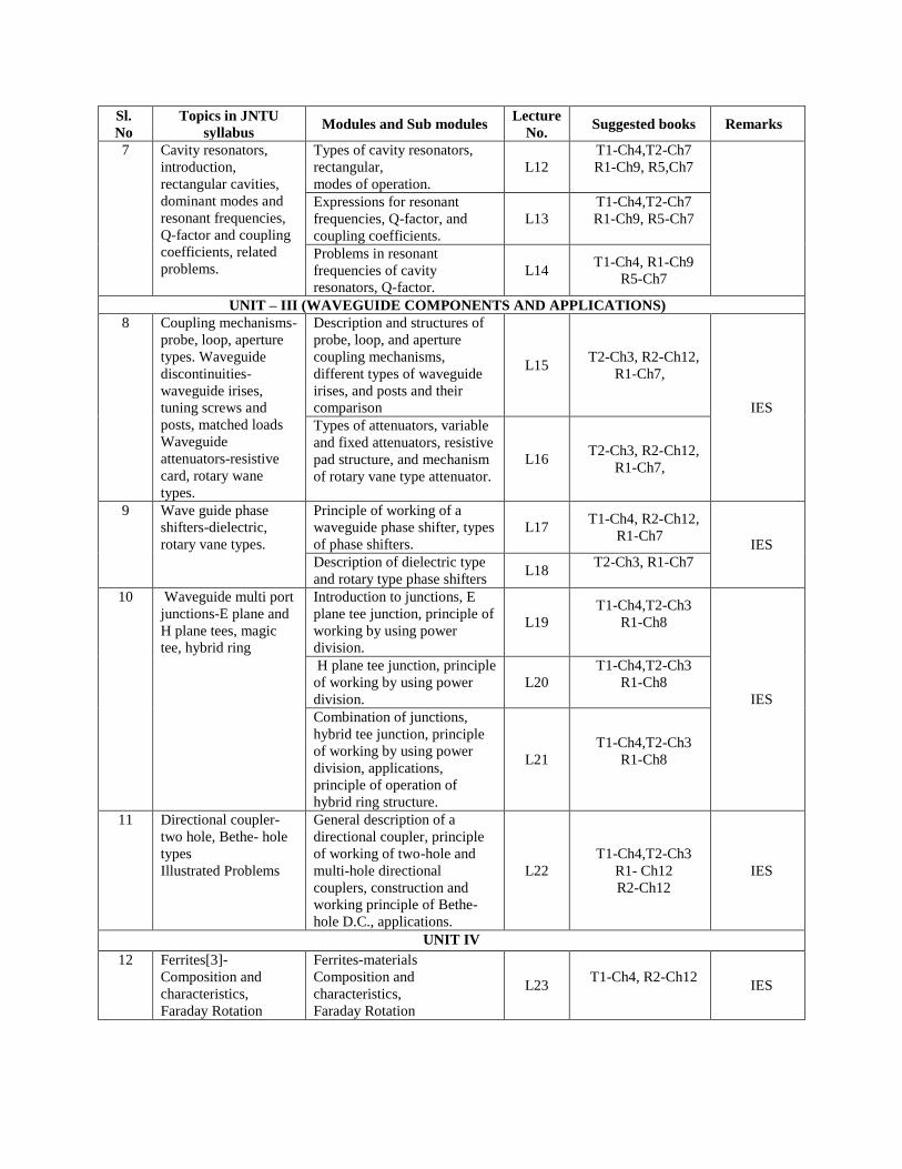
Sl.
No
Topics in JNTU
syllabus Modules and Sub modules
Lecture
No. Suggested books Remarks
7 Cavity resonators,
introduction,
rectangular cavities,
dominant modes and
resonant frequencies,
Q-factor and coupling
coefficients, related
problems.
Types of cavity resonators,
rectangular,
modes of operation.
L12
T1-Ch4,T2-Ch7
R1-Ch9, R5,Ch7
Expressions for resonant
frequencies, Q-factor, and
coupling coefficients.
L13
T1-Ch4,T2-Ch7
R1-Ch9, R5-Ch7
Problems in resonant
frequencies of cavity
resonators, Q-factor.
L14 T1-Ch4, R1-Ch9
R5-Ch7
UNIT – III (WAVEGUIDE COMPONENTS AND APPLICATIONS)
8 Coupling mechanisms-
probe, loop, aperture
types. Waveguide
discontinuities-
waveguide irises,
tuning screws and
posts, matched loads
Waveguide
attenuators-resistive
card, rotary wane
types.
Description and structures of
probe, loop, and aperture
coupling mechanisms,
different types of waveguide
irises, and posts and their
comparison
L15 T2-Ch3, R2-Ch12,
R1-Ch7,
IES
Types of attenuators, variable
and fixed attenuators, resistive
pad structure, and mechanism
of rotary vane type attenuator.
L16 T2-Ch3, R2-Ch12,
R1-Ch7,
9 Wave guide phase
shifters-dielectric,
rotary vane types.
Principle of working of a
waveguide phase shifter, types
of phase shifters.
L17 T1-Ch4, R2-Ch12,
R1-Ch7 IES
Description of dielectric type
and rotary type phase shifters L18
T2-Ch3, R1-Ch7
10 Waveguide multi port
junctions-E plane and
H plane tees, magic
tee, hybrid ring
Introduction to junctions, E
plane tee junction, principle of
working by using power
division.
L19
T1-Ch4,T2-Ch3
R1-Ch8
IES
H plane tee junction, principle
of working by using power
division.
L20
T1-Ch4,T2-Ch3
R1-Ch8
Combination of junctions,
hybrid tee junction, principle
of working by using power
division, applications,
principle of operation of
hybrid ring structure.
L21
T1-Ch4,T2-Ch3
R1-Ch8
11 Directional coupler-
two hole, Bethe- hole
types
Illustrated Problems
General description of a
directional coupler, principle
of working of two-hole and
multi-hole directional
couplers, construction and
working principle of Bethe-
hole D.C., applications.
L22
T1-Ch4,T2-Ch3
R1- Ch12
R2-Ch12
IES
UNIT IV
12 Ferrites[3]-
Composition and
characteristics,
Faraday Rotation
Ferrites-materials
Composition and
characteristics,
Faraday Rotation
L23 T1-Ch4, R2-Ch12
IES
Sl.
No
Topics in JNTU
syllabus Modules and Sub modules
Lecture
No. Suggested books Remarks
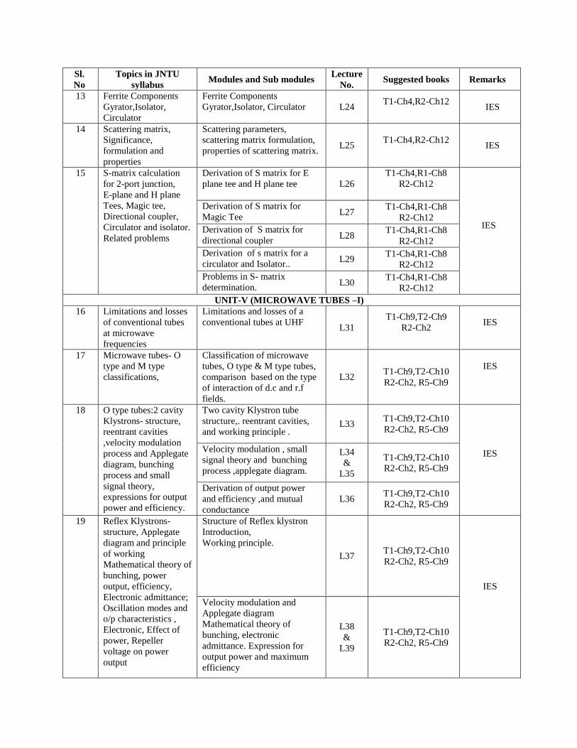
13 Ferrite Components
Gyrator,Isolator,
Circulator
Ferrite Components
Gyrator,Isolator, Circulator L24 T1-Ch4,R2-Ch12
IES
14 Scattering matrix,
Significance,
formulation and
properties
Scattering parameters,
scattering matrix formulation,
properties of scattering matrix. L25
T1-Ch4,R2-Ch12
IES
15 S-matrix calculation
for 2-port junction,
E-plane and H plane
Tees, Magic tee,
Directional coupler,
Circulator and isolator.
Related problems
Derivation of S matrix for E
plane tee and H plane tee L26
T1-Ch4,R1-Ch8
R2-Ch12
IES
Derivation of S matrix for
Magic Tee L27
T1-Ch4,R1-Ch8
R2-Ch12
Derivation of S matrix for
directional coupler L28
T1-Ch4,R1-Ch8
R2-Ch12
Derivation of s matrix for a
circulator and Isolator.. L29
T1-Ch4,R1-Ch8
R2-Ch12
Problems in S- matrix
determination. L30
T1-Ch4,R1-Ch8
R2-Ch12
UNIT-V (MICROWAVE TUBES –I)
16 Limitations and losses
of conventional tubes
at microwave
frequencies
Limitations and losses of a
conventional tubes at UHF L31
T1-Ch9,T2-Ch9
R2-Ch2
IES
17 Microwave tubes- O
type and M type
classifications,
Classification of microwave
tubes, O type & M type tubes,
comparison based on the type
of interaction of d.c and r.f
fields.
L32 T1-Ch9,T2-Ch10
R2-Ch2, R5-Ch9
IES
18 O type tubes:2 cavity
Klystrons- structure,
reentrant cavities
,velocity modulation
process and Applegate
diagram, bunching
process and small
signal theory,
expressions for output
power and efficiency.
Two cavity Klystron tube
structure,. reentrant cavities,
and working principle . L33
T1-Ch9,T2-Ch10
R2-Ch2, R5-Ch9
IES Velocity modulation , small
signal theory and bunching
process ,applegate diagram.
L34
&
L35
T1-Ch9,T2-Ch10
R2-Ch2, R5-Ch9
Derivation of output power
and efficiency ,and mutual
conductance
L36 T1-Ch9,T2-Ch10
R2-Ch2, R5-Ch9
19
Reflex Klystrons-
structure, Applegate
diagram and principle
of working
Mathematical theory of
bunching, power
output, efficiency,
Electronic admittance;
Oscillation modes and
o/p characteristics ,
Electronic, Effect of
power, Repeller
voltage on power
output
Structure of Reflex klystron
Introduction,
Working principle.
L37 T1-Ch9,T2-Ch10
R2-Ch2, R5-Ch9
IES
Velocity modulation and
Applegate diagram
Mathematical theory of
bunching, electronic
admittance. Expression for
output power and maximum
efficiency
L38
&
L39
T1-Ch9,T2-Ch10
R2-Ch2, R5-Ch9
Sl.
No
Topics in JNTU
syllabus Modules and Sub modules
Lecture
No. Suggested books Remarks
UNIT-VI (HELIX TWTS AND M -TYPE TUBES)
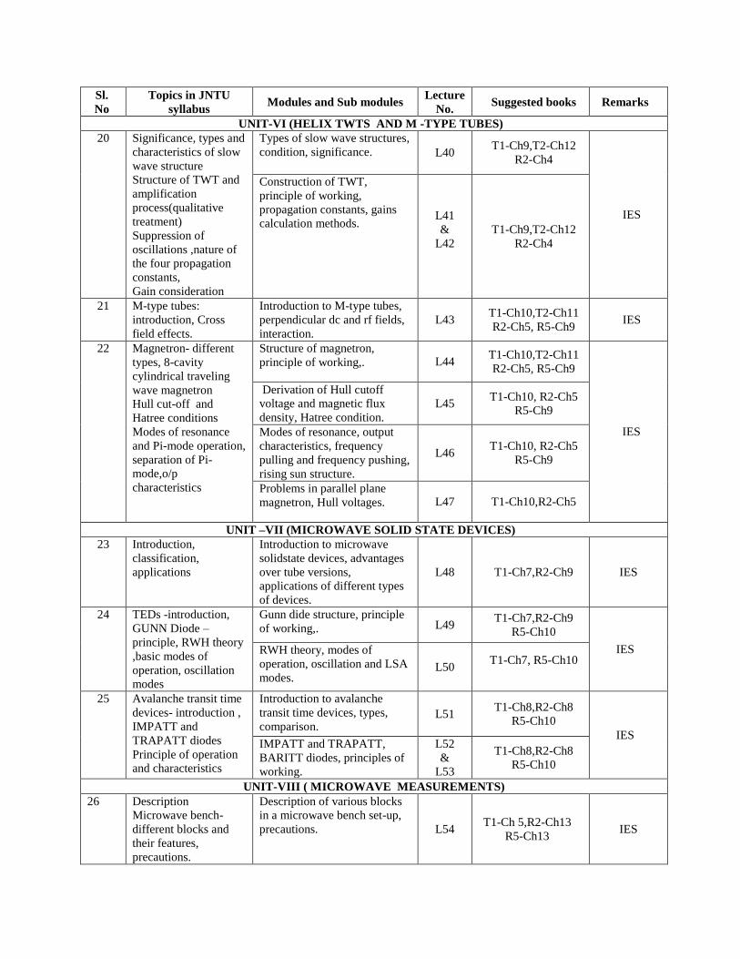
20
Significance, types and
characteristics of slow
wave structure
Structure of TWT and
amplification
process(qualitative
treatment)
Suppression of
oscillations ,nature of
the four propagation
constants,
Gain consideration
Types of slow wave structures,
condition, significance. L40 T1-Ch9,T2-Ch12
R2-Ch4
IES
Construction of TWT,
principle of working,
propagation constants, gains
calculation methods. L41
&
L42
T1-Ch9,T2-Ch12
R2-Ch4
21 M-type tubes:
introduction, Cross
field effects.
Introduction to M-type tubes,
perpendicular dc and rf fields,
interaction.
L43 T1-Ch10,T2-Ch11
R2-Ch5, R5-Ch9 IES
22 Magnetron- different
types, 8-cavity
cylindrical traveling
wave magnetron
Hull cut-off and
Hatree conditions
Modes of resonance
and Pi-mode operation,
separation of Pi-
mode,o/p
characteristics
Structure of magnetron,
principle of working,. L44 T1-Ch10,T2-Ch11
R2-Ch5, R5-Ch9
IES
Derivation of Hull cutoff
voltage and magnetic flux
density, Hatree condition.
L45 T1-Ch10, R2-Ch5
R5-Ch9
Modes of resonance, output
characteristics, frequency
pulling and frequency pushing,
rising sun structure.
L46 T1-Ch10, R2-Ch5
R5-Ch9
Problems in parallel plane
magnetron, Hull voltages. L47 T1-Ch10,R2-Ch5
UNIT –VII (MICROWAVE SOLID STATE DEVICES)
23 Introduction,
classification,
applications
Introduction to microwave
solidstate devices, advantages
over tube versions,
applications of different types
of devices.
L48 T1-Ch7,R2-Ch9 IES
24 TEDs -introduction,
GUNN Diode –
principle, RWH theory
,basic modes of
operation, oscillation
modes
Gunn dide structure, principle
of working,. L49 T1-Ch7,R2-Ch9
R5-Ch10
IES RWH theory, modes of
operation, oscillation and LSA
modes. L50
T1-Ch7, R5-Ch10
25 Avalanche transit time
devices- introduction ,
IMPATT and
TRAPATT diodes
Principle of operation
and characteristics
Introduction to avalanche
transit time devices, types,
comparison. L51
T1-Ch8,R2-Ch8
R5-Ch10
IES IMPATT and TRAPATT,
BARITT diodes, principles of
working.
L52
&
L53
T1-Ch8,R2-Ch8
R5-Ch10
UNIT-VIII ( MICROWAVE MEASUREMENTS)
26 Description
Microwave bench-
different blocks and
their features,
precautions.
Description of various blocks
in a microwave bench set-up,
precautions. L54 T1-Ch 5,R2-Ch13
R5-Ch13 IES
Sl.
No
Topics in JNTU
syllabus Modules and Sub modules
Lecture
No. Suggested books Remarks
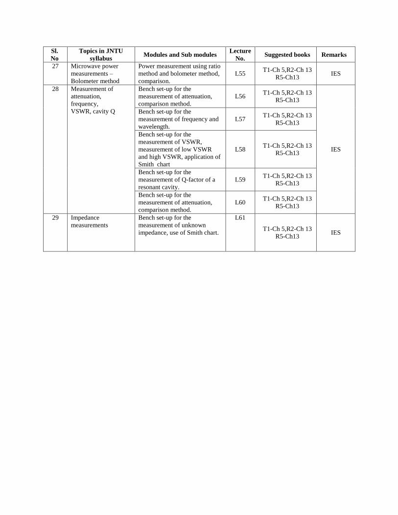
27 Microwave power
measurements –
Bolometer method
Power measurement using ratio
method and bolometer method,
comparison.
L55 T1-Ch 5,R2-Ch 13
R5-Ch13 IES
28 Measurement of
attenuation,
frequency,
VSWR, cavity Q
Bench set-up for the
measurement of attenuation,
comparison method.
L56 T1-Ch 5,R2-Ch 13
R5-Ch13
IES
Bench set-up for the
measurement of frequency and
wavelength.
L57 T1-Ch 5,R2-Ch 13
R5-Ch13
Bench set-up for the
measurement of VSWR,
measurement of low VSWR
and high VSWR, application of
Smith chart
L58 T1-Ch 5,R2-Ch 13
R5-Ch13
Bench set-up for the
measurement of Q-factor of a
resonant cavity.
L59 T1-Ch 5,R2-Ch 13
R5-Ch13
Bench set-up for the
measurement of attenuation,
comparison method.
L60 T1-Ch 5,R2-Ch 13
R5-Ch13
29 Impedance
measurements
Bench set-up for the
measurement of unknown
impedance, use of Smith chart.
L61
T1-Ch 5,R2-Ch 13
R5-Ch13 IES
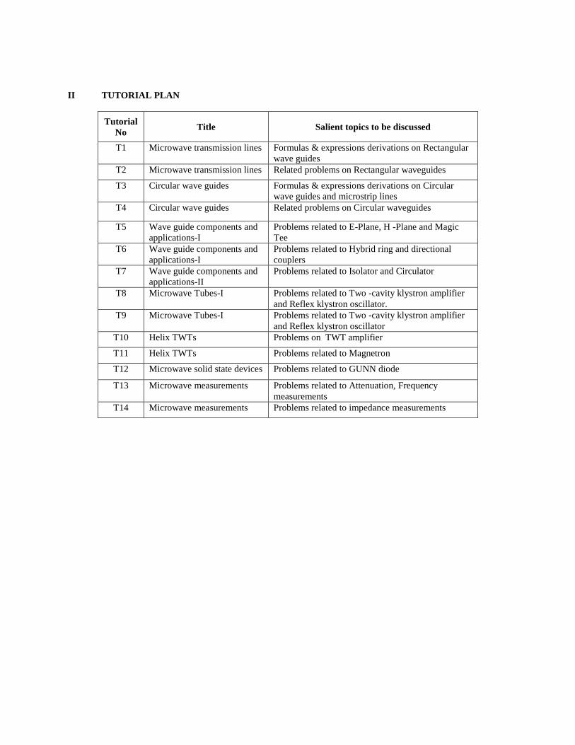
II TUTORIAL PLAN
Tutorial
No Title Salient topics to be discussed
T1 Microwave transmission lines Formulas & expressions derivations on Rectangular
wave guides
T2 Microwave transmission lines Related problems on Rectangular waveguides
T3 Circular wave guides Formulas & expressions derivations on Circular
wave guides and microstrip lines
T4 Circular wave guides Related problems on Circular waveguides
T5 Wave guide components and
applications-I
Problems related to E-Plane, H -Plane and Magic
Tee
T6 Wave guide components and
applications-I
Problems related to Hybrid ring and directional
couplers
T7 Wave guide components and
applications-II
Problems related to Isolator and Circulator
T8 Microwave Tubes-I Problems related to Two -cavity klystron amplifier
and Reflex klystron oscillator.
T9 Microwave Tubes-I Problems related to Two -cavity klystron amplifier
and Reflex klystron oscillator
T10 Helix TWTs Problems on TWT amplifier
T11 Helix TWTs Problems related to Magnetron
T12 Microwave solid state devices Problems related to GUNN diode
T13 Microwave measurements Problems related to Attenuation, Frequency
measurements
T14 Microwave measurements Problems related to impedance measurements
7.5.12. QUESTION BANK
UNIT-I
1. i. Explain the wave impedance of a rectangular waveguide and derive the expression for the wave impedance
of TE and TM modes.
ii. Calculate the cut-off frequency of the following modes in a square waveguide 4 cm × 4 cm TE10, TM11
and TE22. (Nov13)
2. i. Show that TM01 and TM10 modes in a rectangular waveguide do not exist.
ii For a wave guide having cross section 3cm × 2cm, compute the cut-off frequency in the TE01 mode.
Also, calculate the phase velocity and guide wavelength at a frequency equal to 50% above the cut-off
frequency. (Nov/Dec 13)
3. i. Use Maxwell’s equations to show that it is impossible for TEM wave to exit within any single conductor
wave guide.
ii. Explain the significance of mode indices ‘m’ and ‘n’ for fields in the rectangular waveguide.
iii. Design a dielectric fields (εr=4) rectangular waveguide such that the cut-off frequency for the dominant
mode is 14 GHz and the cut-off frequency for the TM11
mod is 30 GHz
(Dec 12)
4. i. Determine the phase and group velocities, guide wavelength and characteristic impedance for a rectangular
guide of 2.5 cm. x 1.0 cm. cross-section, for the TE20 mode at 15 GHz.
ii. Identify the frequency ranges associated with microwave frequencies and hence distinguish between the
different types of standard microwave band designations (Nov 11)
5. Given HZ = Ho Cos (mπx/a).Cos(nπy/b) .exp(-jβZ) A/m., establish the relations for the E field components
of TEmn modes in a rectangular waveguide. Explain the meaning of the different symbols involved. Give its
typical sketch in a rectangular coordinate system, and list out the boundary conditions for the tangential E
components involved. (Nov 11)
7. i. For a rectangular guide of 7.2 cm x 3.4 cm. determine m, n and all the propagation characteristics for the
lowest possible TM mode at 6 GHz (no derivations). Can a TE mode exist for such m and n? If so, what
will be the change in propagation characteristics for such a TE mode?
ii. Determine the changes in of the above modes, if this waveguide is filled with a medium of dielectric
constant 4.0? (Nov 11)
8. i. Starting with the equation for the propagation constant of a mode in a rectangular wave guide, derive the
expression λg = λ0λc
√λ02+λc
2
Where λg is the guide wave length and λc is the cutoff wave length
ii. An air filled rectangular wave guide has the dimensions of 4 and 3cm and is supporting TE10 mode at a
frequency of 9800MHz. Calculate
a. The wave guide impedance
b. The percentage change in the impedance for a 10% increase in the operating frequency. (May 10)
9 i. Derive the wave equation for a TE wave and obtain all the field components in a rectangular wave guide.
ii. Consider a rectangular wave guide of 8 cm x 4 cm. Given critical wave length of TE10 = 16cm, TM11 =
7.16 cm, TM21 = 5.6 cm. What modes are propagated at a free space wave length of λ
a. 5 cm and
b. 10 cm. (May 10,09, 08, 07, Sep 06)
10. i. Derive the wave equation for a TM wave and obtain all the field components in a rectangular wave guide.
ii. A rectangular wave guide with dimension of 3 x 2 cm operates in the TM11 mode at 10 GHz. Determine the
characteristic wave impedance.
11. i. Obtain the field equations of rectangular wave guides in TEmn modes.
ii. An air field rectangular wave guide of dimensions (7x3.5 cm) operates in the dominant TE10 mode.
a. Find the cut off frequency
b. Find the phase velocity of the wave in the guide at the frequency of 3.5 GHz.
c. Determine the guided wave length at the same frequency. (May 10)
12 i. Derive the expressions for cut off frequency, phase constant, group velocity, phase velocity and wave
impedance in a rectangular wave guide.
ii. An rectangular wave guide is filled by dielectric material of 2εr= 9 and has dimensions of 7 × 3.5 cm. It
operates in the dominant TE mode.
a. Determine the cut off frequency.
b. Find the phase velocity in the guide at a frequency of 2 GHz.
c. Find the guided wave length at 2 GHz. (May 09)
13. i. Find expressions for the electric surface current density on the wall of a rectangular wave guide for a TE10
mode.
ii. A rectangular wave guide of cross section 5 cm × 2 cm is used to propagate TM11 mode at 9 GHz.
Determine the cut off wave length and wave impedance. (May 09)
14. i. Mention different microwave regions & band designations.
ii. Discuss the war and peace time applications of microwaves. (May 09, Sep 08)
15. i. Derive the wave equation for a TM wave and obtain all the field components in a rectangular wave guide.
ii. A rectangular wave guide with dimension of 3 × 2 cm operates in the TM11 mode at 10 GHz. Determine
the characteristic wave impedance. (May 09, 08)
16. Show that the TEM, TM01 and TM10 modes in a rectangular wave-guide do not exist. (May 09, 06)
17. i. What is a cavity resonator? Explain the principle of operation of a rectangular cavity resonator?
ii. Explain why single conductor hollow or dielectric filled wave guide cannot support TEM waves.
(May 09, 06)
18. i. Derive the expressions for cutoff frequency, phase constant, group velocity, phase velocity and wave
impedance in rectangular wave guide, for TE modes.
ii. An air filled circular waveguide is to be operated at a frequency of 6 GHz and is to have dimensions such
that fc=0.8f for the dominant mode. Determine
i. The diameter of the guide ii. Guide wave length and iii. Phase velocity in the guide (May 09, Nov 05)
19. i. A rectangular guide of inner dimensions 2.5 cm × 1.2 cm is to propagate energy in TE10 mode. Calculate
the cut off frequency. If the frequency of signal is 1.2 times this cut off frequency, compute the guide wave
length, phase velocity and wave impedance. Derive the relations used.
ii. Prove that for any wave guide. (Sep 08)
20. i. An air field rectangular wave guide has dimensions of a = 6 cm, b = 4 cm. The signal frequency is 3 GHz.
Compute the following for TE10, TE11 modes.
a. Cut off frequency
b. Wave length in the waveguide
c. Phase constant and phase velocity in the wave guide
d. Group velocity and wave impedance in the wave guide.
ii. Discuss the methods of excitations of modes in the rectangular wave guide. (Sep 08)
21. i. Derive the expression for guide wave length of TEmn mode in rectangular wave guide.
ii. What are the advantages of dominant mode propagation? (May 08)
22. i. What are TEM, TE, TM and HE modes? Sketch the field patterns for dominant modes in a rectangular
wave guides.
ii. A rectangular wave guide has a = 4 cm, b = 3 cm as its sectional dimensions. Find all the modes which
will propagate at 500 MHz (May 08)
23. i. Discuss the attenuation in wave guides in detail.
ii. A wave guide operating in TE10 mode has dimensions a = 2.26 cm and b = 1 cm. The measured guide
wave length is 4 cm. Find
a. Cut off frequency of the propagating mode
b. The frequency of operation
c. Maximum frequency of propagation in this mode. (May 08)
24. The field component is given as.
Determine
i. The mode of operation
ii. The cut off frequency
iii. The phase constant
iv. The propagation constant
v. The wave impedance. (May 08, 07, Sep 06)
25. A 6.0 GHz signal is to be propagated in the dominant mode in a rectangular waveguide. If its group
velocity is to be 80% of the free space velocity of light. What must be the breadth of the waveguide?
What impedance will it offer to this signal if it is correctly matched? (May 07, Sep 06)
26. Distinguish between TEM, TE and TM modes of the propagation in rectangular wave guides.
(May 06)
27. If the height of the wave guide is halved, its cut -off wave length will be (IES 03)
28. In a rectangular wave guide with b roader dimension a and narrow dimension b, the
dominant mode of Microwave propagation would be? (IES 03)
29. A metal probe inserted into a rectangular waveguide through the broader wall of the guide
will provide a property across the guide, this property is know n as? (IES 03)
30 An X-band rectangular waveguide filled with a dielectric of 2.6 is operating at 9.5 GHz. Calculate group
and phase velocities. Also calculate the TE and TM wave impedances. (IES 02)
31. An air filled hollow rectangular conducting waveguide has cross-section of 8 x 10 cm. How many TE
modes will this waveguide transmit at frequencies below 5 GHz? How these modes designated and what
are the cut-off frequencies? (IES 2000)
UNIT-II
1 i. Derive the expression for the characteristic impedance of micro strip lines.
ii. Find the first five resonances of an air-filled rectangular cavity with dimensions of a = 5 cm, b = 4 cm and c
= 10 cm (d >a >b). (Nov13)
2. i. Prove by Maxwell’s equations that it is impossible for a TEM wave to be propagated inside a hollow
conducting tube, whether cylindrical or rectangular.
ii. An air filled circular waveguide is to be operated at a frequency of 6 GHz and is to have dimensions such
that fc = 0.8 f for the dominant mode of operation. Determine
(i) Diameter of the guide (ii) the wave length ( λg) and (iii)the phase velocity in the guide.( Nov/Dec 13)
3. i. Derive the expression for power transmission in rectangular waveguides supporting only dominate
mode propagation. On what factor does the power handling capacity of the waveguide mainly depend?
ii. Write a brief not on micro-strip lines. iii. Find the resonant frequencies of first 3 lowest order modes in a n air filled rectangular cavity resonator
of dimensions (5cmx4cmx2.5cm) (Dec 12)
4. i. For an air-filled rectangular guide cavity resonator of 4 cm x 2 cm. cross section and 5 cm. axial length,
determine the resonant frequency of the lowest 3 possible modes.
ii. Sketch and explain the constructional features and field lines associated with the propagation in Microstrip
Lines. What are the applications of such lines at microwave frequencies? (Nov 11)
5 i. Identify the dominant mode configurations of Rectangular and Circular Waveguides, Rectangular, Cubical
and Circular Cavity Resonators. What are the common types of losses that exist in all these structures?
What happens to their performances as the frequency of application increases?
ii. An air-filled circular guide operates at 9.375 GHz with a guide wavelength of 5.0 cm. Determine its phase
constant, group velocity and Zo . (Nov 11)
6. i. List out the first 5 modes of propagation in a circular waveguide, defining and accounting for the dominant
and degenerate modes in them.
ii. Define and establish an expression for the Q factor of a cavity resonator. Hence distinguish between Qext,
Qo , QLoaded and QUnloaded , and list their inter-relation. (Nov 11)
7. i. Evaluate the phase and group velocities, Zo for the lowest order TM mode in an air filled circular
waveguide of 2.0 cm. diameter at 12 GHz. (Data : X01= 2:405andX; 11= 1:841):
ii. Explain how a rectangular waveguide can be configured as a Cavity Resonator. Hence establish an
expression for its dominant mode resonant frequency if its axial dimension is larger than the cross sectional
dimensions. (Nov 11)
8. i. Account for the different types of power losses in a rectangular waveguide. Hence obtain an expression for
its attenuation factor in terms of power lost and power transmitted.
ii. For an air-filled rectangular guide of a=2.3 cm, and b= 1.0 cm. determine the different types of
wavelengths and Zo associated with the TE01 mode at 16 GHz. (Nov 11)
9. i. Discuss the power transmission in circular wave guides.
ii. An air filled circular wave guide of 2 cm inside radius is operated in the TE01
mode.
a. Compute the cut off frequency
b. If the guide is to be filled with a dielectric material of ε = 2.25, to what value must its radius be changed
in order to maintain the cut off frequency at its original values. (May 10, Sep 08)
10. i. Derive the Q for TM111
mode of rectangular cavity assuming lossy conducting walls and lossless dielectric.
ii. The quality factor of micro strip line is reciprocal of the dielectric loss tangent ¸ and is relatively constant
with frequency. Prove this statement. (May 10, Sep 08)
11. i. What is cavity resonator? Explain the principle of operation of rectangular cavity resonator.
ii. A rectangular cavity resonator has dimensions of a=5cms, b=2cms and d=10cms. Compute the resonant
frequency of the dominant mode if the cavity is
a. Air filled and
b. Dielectric filled with =2.3 (May 10)
12. i. Explain how a rectangular cross section of a micro strip line can be transformed in to equivalent circular
conductance.
ii. In the above transformation, what is the significance of t/w ratio? (May 10)
13. i. State the factors up on which the attenuations constant of a parallel strip line are dependent.
ii. Derive an expression for the attenuation factor of a micro strip line. (May 09)
14. i. Prove that a cavity resonator is nothing but an LC circuit.
ii. Derive an expression for Q of a cavity supporting TE101 mode. What is the resonant frequency of the cavity
if each side of the guide is 3 cm? (May 09)
15. i. Distinguish between the properties of TEM mode of propagation and that of TE and TM type of
propagation.
ii. Write short notes on “Cavity resonators and its applications”. (May 09)
16. i. With a schematic diagram, explain the construction of a micro strip line.
ii. Mention the advantages of strip lines over other transmission lines. (Sep 08)
17. i. What is the effect of conductivity on the dielectric loss of a strip line?
ii. Derive the expression for attenuation constant for dielectric loss. (Sep 08)
18. i. What is the impact of skin effect on a micro strip line?
ii. Derive an expression for attenuation factor for ohmic skin loss. (May 08)
19. i. Derive the Q for TM111
mode of rectangular cavity assuming lossy conducting walls and lossless dielectric.
ii. The quality factor of micro strip line is reciprocal of the dielectric loss tangent and is relatively constant
with frequency. Prove this statement (Sep, May 08)
19. i. Explain the concepts of propagation delay time for a strip line.
ii. Is the effective dielectric constant of a micro strip line a function of relative dielectric constant justify.
(May 08)
20 Derive the expression for the resonant frequency of a rectangular cavity resonator (May 07)
21. i Write a short notes on “Cavity resonators’. (May 05)
ii Derive the expression for the resonant frequency of a rectangular cavity resonator.
22. i. An X band waveguide filled with a dielectric is operating at 9 GHz. Calculate the phase and group
velocities in the wave-guide. Take r has 2.25 for the dielectric.
ii. What are cavity resonators? What are their most desirable properties? (May 05)
23 i. A rectangular cavity of width ‘a’ height ‘b’ and length ‘d’ is to resonance with TE101
mode obtain the
frequency of response. If resonant frequency is 10GHz, a=2 cm. and b=1cm, find ‘d’
ii. An air filled resonant cavity with dimension a=5 cm, b=4 cm and c=10 cm is made of copper. It is filled
with a lossless material where permeability is 1. Find the resonant frequency and the quality factor for the
dominant mode. (May 05)
24. Explain the methods of excitation and tuning of a cavity resonator. (May 04)
25. As related to excitation and coupling of microwave resonators, define the following terms:
i. Critical coupling ii. Under coupling iii.Over coupling (May 04)
How is coefficient of coupling defined in Microwave circuits? Define the Q factors involved in these
cases.
26. Guided wavelength of a rectangular waveguide (1 D 2.285 cm x 1.016 cm) is 5.42 cm. When the
waveguide is short-circuited, find the distance between two consecutive voltage minimum positions of
standing wave pattern so formed. Obtain the operating frequency of the microwave source. (Nov 04)
27 The inner dimension of an x-band WR 90 waveguide are a= 2.286cm and b = 1.016cm. Assume that the
wave guide is air filled and operates in dominant TE10 mode, and can be transmitted at f =9 GHz in the
wave guide before air break down occurs. Derive all necessary equations. (IES 03)
28. What three characteristics of waveguides are affected by the addition of a ridge to a rectangular
waveguide? (IES 03)
UNIT – III
1.i. Explain coupling probes and coupling loops.
ii What is phase shifter? Explain its principles of operation with a neat sketch. Give its applications. (Nov13)
2.i. What is meant by normalized voltage and normalized current with respect to the
microwave circuit concept. Draw a neat sketch of a Magic Tee and obtain its S matrix.
Explain two applications of Magic Tee.
ii. Using the properties of scattering matrix of a lossless, reciprocal microwave junction, prove that for a four
port network if all the four ports are matched, the device shall be a directional coupler. (Nov/Dec 13)
3. i. Distinguish between E-plane and H-plane Tees and hence discuss the construction and working of a
Magic-Tee
ii. Write a note on different types of attenuators used in microwave frequency range. (Dec 12)
4. i. With reference to a 4-port symmetrical 2-hole coupler, define and distinguish between the terms :
Coupling, Directivity, Isolation and Insertion Loss. How can this coupler be configured as a forward
directional coupler? How can the coupling be varied in this case?
ii. List out the output characteristics of a Magic Tee, when
a. in-phase inputs are fed at both the main arm ports, and
b. input is fed at the series arm port. (Nov 11)
5. i. With neat schematics, explain the need and functioning of a Matched Waveguide Load. What should
be its reflection coefficient and VSWR?
ii. With neat sketches, account for the differences in transmission characteristics of 3-port Series and Parallel
Tee Junctions. (Nov 11)
6. i. What is the need for phase shifters at microwave frequencies? Explain the concept of realizing phase
shifting through Dielectric Materials.
ii. List out the 3 Theorems associated with the 3-port Tee Junctions, and mention their applications.(Nov 11)
7. i. Describe the characteristic features and mention the applications of:
a. Resonant Windows,
b. Tuning Screws and Posts.
ii. What is a Directional Coupler? List out two different types of couplers, identifying the phenomenon of
coupling, and compare their requirements and demerits. (Nov 11)
8. i. Derive the expression for the coupling and directivity of a two hole directional coupler.
ii. There are two identical directional couplers connected back to back to sample incident and re ected powers.
The outputs of the couplers are 12 mW and 0.12 mW respectively. What is the VSWR in the guide.
(May 10) 9. i. Describe wave guide matching terminations with neat sketches.
ii. Explain for what purpose the posts and screws are used in wave guide. (May 10)
10. i. Sketch a 4 port hybrid junction and justify that it is a basically a 3 dB directional coupler.
ii. A matched generator with a power of one watt is connected to the H arm of magic tee C (port 4). The E
arm (port 3) is match terminated and the length of the coplanar arms is the same. Compute the power
delivered to the termination at port 1, 2 and 3 and the power reacted at port 4 when ports 1 and 2 are match
terminated.
(May 10)
11. i. Draw E - plane Tee diagram and state its properties.
ii. Explain the principle of Ferrite phase shifter. (May 09)
12. i. What is the magic associated with a Magic tee? Illustrate its applications. (May 09)
ii. Discuss how wave equatio ns are useful in understanding the propagation of EM waves in wave guides.
13. i. Explain the operation of a directional coupler with the help of a sketch, showing the field lines at the
junction.
ii. A 20 dB coupler has a directivity of 30 dB. Calculate the value of isolation. (May 09)
14. i. How is magic Tee different from hybrid ring Compare their characteristics? (May 09)
ii. Write short notes on “Rotary vane Attenuator”
15. i. Show the attenuation produced by rotary vane attenuator is given by-40 log (sin)
ii. Describe in detail about linear phase changer. (May 09, Sep, May 08)
16. i. Sketch a 4 port hybrid junction and justify that it is a basically a 3 dB directional coupler.
ii. A matched generator with a power of one watt is connected to the H arm of magic tee C (port 4). The E
arm (port 3) is match terminated and the length of the coplanar arms is the same. Compute the power
delivered to the termination at port 1, 2 and 3 and the power reflected at port 4 when ports 1 and 2 are
match terminated. (Sep, May 08)
17. i. Derive the expression for the coupling and directivity of a two hole directional coupler.(Sept 08)
18. i. With a schematic diagram, explain the construction of a micro strip line.
ii. Mention the advantages of strip lines over other transmission lines. (Sep 08)
19 Write short notes on:
i. Wave guide Irises
ii. Rat Race hybrid.
iii. Dielectric phase shifters. (May 08)
20. i. What is magic Tee? Describe the properties of magic Tee, giving its S-Matrix.
ii. Show a wave-guide with cylindrical post and describe its behavior. How can it be used, when it is inserted
half way into the wave-guide? (May 08)
21. i. Why ‘Ferrites’ are used in microwave passive devices? Explain.
ii. Scattering matrix is a unitary matrix. Prove this statement. (May 08)
22. i Explain the difference between
i. E plane Tee ii. H- Plane Tee
Explain clearly why do you call them series and parallel Tee respectively.
ii Describe with a neat sketch a precision Attenuator, and Explain its operation (May 07)
23 i. Sketch a 4 port Hybrid junction. Justify that it is basically a 3 dB directional coupler.
ii. A 2o mW signal is fed into the series arm of a loss less magic tee junction. Calculate the power delivered
through each port when other ports are terminated in matched load. (Sep 07)
24. i. State the properties of E plane Tee and H plane Tee.
ii. Show that a symmetrical magic Tee is a 3dB directional coupler (May 05, Sep 07)
25. Write short notes on the following.
i. Directional coupler.
ii. Wave guide windows.
iii. Flap attenuator. (Sep 07, May 07, 06,05)
26. Explain the construction, operation and applications of the following microwave components.
i. Directional couplers.
ii. Wave guide Tees. (May 07)
27. i. Derive the expressions for coupling factor and directivity of a two hole directional coupler.
ii. What are the different types of matching elements normally used in wave guide system? Distinguish
between magic Tee and rat race hybrid. (May 07)
28. i. Discuss and compare the characteristics of E-plane Tee and H-Plane Tee.
ii. Write short notes on “Inductive and capacitive posts”. (Sep 06,May 05)
29. Write short notes on the following.
i. Multi hole directional coupler.
ii. Rotary phase shifter. (Sep 06)
30. i. What is a directional coupler? A 20dB coupler has a directivity of 30dB. Calculate the value of isolation,
defining all the terms involved.
ii. Explain the functioning of “rotary Vane attenuators”. (Sep 06,May 05)
UNIT-IV
1. i. Derive the scattering matrix of H- plane Tee?
ii. What are the properties of S matrix? Derive the scattering matrix for a 3 port circulator? (Nov13)
2. i What are the properties of ferrites at microwave frequencies? What is Faraday rotation? Show that it is a
non-reciprocal phenomenon.
ii. List the basic characteristics of a circulator. Discuss any one type. Obtain its S matrix. (Nov/Dec13)
3. i. What is a scattering matrix? Discuss the importance of S-parameters. List the properties of S-matrix.
ii. What is Faraday Rotation Principle? List the properties of ferrites in the working of an isolator.
iii. Build the S-matrix of E-[lane Tee Junction. (Dec 12)
4. i. Establish the Scattering Matrix for a 3-port circulator.
ii. A matched Isolator has an Insertion Loss of 0.6 dB and an Isolation of 20 dB. Obtain its S-matrix and
input VSWR. (May 11)
5. i. With reference to a 4-port symmetrical 2-hole coupler, define and distinguish between the terms: Coupling,
Directivity, Isolation and Insertion Loss. How can this coupler be congrued as a forward directional
coupler? How can the coupling be varied in this case?
ii. List out the output characteristics of a Magic Tee, when
i. in-phase inputs are fed at both the main arm ports, and
ii. input is fed at the series arm port. (May 11)
6. i. A 2-port Reciprocal Junction has an Impedance Matrix with Z11 = Z22 = 4.0, and Z12 = 2.0. Find its S-
Matrix.
ii. Explain the Unitary Condition for S-Matrix, and establish the same for a n-port microwave junction, citing
the requirements. (May 11)
7. i. What is the need for phase shifters at microwave frequencies? Explain the concept of realizing phase
shifting through Dielectric Materials.
ii. List out the 3 Theorems associated with the 3-port Tee Junctions, and mention their applications.
(May 11) 8. i. Explain the significance of the S-Matrix and its elements. What happens if it is reciprocal and unitary ?
ii. Explain the functioning of an Isolator with neat schematics. (May 11)
9. i. Discuss propagation of microwave energy in ferrites.
ii. A matched isolator has insertion loss of 0.5 dB and isolation of 25 dB. Find the scattering
coefficients. (May 10)
10. i. Explain the properties of scattering matrix.
ii. Determine scattering matrix for the following junction as shown in figure
(May 10)
11. i. Derive the S parameters for a two port microwave junction.
ii. Prove that any lossless, matched, non reciprocal three port microwave junction is a perfect three port
circulator. (May 10)
12. i. Scattering matrix is a unitary matrix. Prove this statement.
ii. Obtain the S - matrix for a magic Tee with respect to its properties. (May 10)
13. i. What are the properties of ferrite material for applications at microwave frequencies? Explain the principle
of ferrite phase shifter.
ii. State and prove the S - matrix properties of a lossless junction. (May 09)
14. i. What are ferrites? What property do they have different from ordinary conductors and insulators?
ii. What is scattering matrix? Explain the significance of S - matrix. (May 09)
15. i. Explain Faraday rotation with a neat diagram? Explain the working of ferrite isolator.
ii. Give the scattering matrix of 3 port circulator. The scattering variables measured at a port are
a = 5 + j2 and b = 2 + j2
The normalizing impedance Z0 = 50 ohms. Calculate the voltage and current. (May 09)
16. i. What is scattering matrix? Derive the S matrix of the two port junction shown in figure7b
ii. Explain the principle of operation and characteristics of ferrite phase shifters. (May 09)
17. i. Obtain the S-Matrix of an ideal 3dB directional coupler.
ii. Write short notes on “Ferrite Devices”. (May 09,Sep 07)
18. i. Sketch a 4 port Hybrid junction. Justify that it is basically a 3 dB directional coupler.
ii. A 20-mw signal is fed into the series arm of a loss less Magic Tee junction. Calculate the power delivered
through each port when other ports are terminated in matched load. (May 09,Nov 05)
19. i. Describe microwave component which makes use of Faraday rotation principle.
ii. What are the advantages of scattering matrix representation over impedance or admittance matrix
representation? (May 08)
20. What is Faraday rotation? Explain the working of a ferrite circulator with neat sketches. How can it be used
as an isolator? (May 08)
21. i. What is Faraday rotation? Explain how a three port circulator operates.
ii. Write short notes on “Properties of S - matrix”. (May09,08, 06,05)
22. i. Derive the S matrix for series Tee using the properties of S parameters. (Sep 08, May 05)
ii. A three port circulator has an insertion loss of 1 dB, isolation 30 dB and VSWR = 1.5. Find the S matrix.
23. i. Explain the principle of operation of an isolator? What is the significance of using isolator in microwave
circuits?
ii. Why are S - parameters used at microwave frequencies explain. Give the properties of S -parameters.
(Sep 08) 24. What is a Gyrator? Describe how isolators can be realized by using Gyrators and Hybrids. Give the S
matrix for ideal Gyrators. (Sep 08)
25. i. Explain the characteristics of ferrite materials.
ii. Derive the S - matrix for 4 port directional coupler when the coupling factor is 3dB. (May 08)
26. i. Explain the working of two hole directional coupler with a neat diagram.
ii. Explain about E plane Tee junction with a neat sketch. Why it is called a series Tee? (May 08)
27. i. Enumerate the properties of S parameters.
ii. Formulate the S parameter matrix of a 4 port circulator. (May 08)
28. i. Derive the expressions for coupling factor and directivity of a two hole directional coupler.
ii. What are the different types of matching elements normally used in wave guide system? Distinguish
between magic Tee and rat race hybrid. (May 08)
29. Explain the construction, operation and applications of the following microwave components.
i. Circulator
ii. Gyrator. (May 08, 06, 05)
30. i. Derive the S matrix for E-plane Tee.
ii. What is Faraday’s Rotation? What are its applications in microwaves? Explain in detail. (Sep 07)
31 Find the scattering coefficients for an ideal directional coupler having a coupling coefficient C=3 dB.
(IES 91)
32. A two port non-reciprocal device which produces minimum attenuation EM wave
propagation in one direction and a very high attenuation in opposite direction is generally
known as. (IES 03)
UNIT-V
1. i. Explain the principle of operation of a two cavity klystron with a neat diagram?
ii. The operating frequency of a reflex klystron is 5 GHz, it has a DC beam of 250V, a repeller spacing of 0.1
cm for 1 43mode. Determine the maximum value of power and the corresponding repeller voltage for a
beam current of 60mA. (Nov 13)
2. i. Draw the schematic diagram of a reflex klystron. Explain its operation. Draw the power output and
frequency characteristics of a reflex klystron and explain.
ii. Derive an expression for the maximum efficiency of a reflex klystron oscillator. (Nov/Dec13)
3. i. What are limitations of conventional tubes at microwave frequencies?
ii. Discuss in detail bunching process for a two cavity Klystron amplifier and obtain expression for bunching
parameter.
iii. What are the performance characteristics of a klystron amplifier? (Dec 12)
4. i. With reference to 2-Cavity and Single Cavity Klystrons, compare the following
i. Bunching Parameters, and their optimum values for maximum efficiency,
ii. Types of Cavities used,
iii. Grid Interceptions, and
iv. Type of energy delivered in the output cavities.
ii. List out the microwave applications of 2-Cavity Klystrons and Reflex Klystrons. (May 11)
5. i. Derive the expression for the beam current of a 2-Cavity Klystron Amplifier, and hence evaluate its power
output and maximum electronic efficiency.
ii. A Reflex Klystron has a dc beam voltage of 2500 V, repeller-cavity spacing of 6 mm. Find the repeller
voltages for the tube to oscillate at 3 GHz, in 1 3/4 and 2 3/4 modes, and the corresponding maximum
permissible efficiencies. (May 11)
6. 1. List out the expressions for the Zin , Yin and Gain-Bandwidth Product of conventional tubes at UHF. What
happens to the resulting circuits at still higher frequencies ?
ii. Write short notes on Electronic Admittance of a Reflex Klystron tube, and its significance. (May 11)
7. i. With a neat velocity diagram, explain the process of energy transfer in 2-cavity Klystron cavities, and
account for the signal amplification.
ii. A Reflex Klystron operates at Vo = 300 V; Vr = -500 V and f = 10 GHz. If it is to operate in the same
mode at a frequency of 9.5 GHz, find the re ector voltage required (no derivations needed). (May 11)
8. i. Derive the expression for bunching parameter of reflex klystron
ii. A reflex klystron operates at the peak of n = 2 mode. The dc power input is 40mV. If 20% of the power
delivered by the beam is dissipated in the cavity walls, find the power delivered to the load. (May 10)
9. i. Give the analysis of reflex klystron & derive the expression for repeller voltage Vr in terms of l,n & V
a.
ii. Explain clearly the classification of microwave sources. (May 10)
10. i. A reflex klystron has following parameters: V0 = 3000V; L = 5mm; f = 2GHZ:
Calculate the repeller voltage for which the tube can oscillate in mode.
ii. Give the quantitative analysis of electron bunching in two cavity klystron. (May 10)
11. i. The parameters of a two cavity klystron are
Vb = 900v: Rd = 30k ohm; Ib = 20mA; f = 32GHZ d = 10-3m:
Determine
a. Electron velocity
b. Transit angle
c. Beam coupling coefficient
ii. Draw the voltage characteristics of Reflex klystron & explain. (May 10)
12. i. A reflex klystron operates with Vb = 400V, Rsh = 20kΩ, f = 9GHZ, L = 10-3m. n = 2. Find the repeller
voltage & electronic efficiency.
ii. Derive the expressions used in the above problem. (May 09)
13. i. Derive the expression for output power & Efficiency of a 2 cavity klystron. (b) In a two-cavity klystron the
parameters are input power = 10mv, voltage gain = 20dB, Rsh of input cavity = 25k Ω, Rsh of output cavity
= 35k - , load resistance =40k - . Find the input voltage, output voltage & power to the load.
(May 09) 14. i. Discuss the applications of microwaves. What are the limitations of conventional tubes at UHF.
ii. Derive an expression for the efficiency of a two-cavity Klystron amplifier. Show that the theoretical
efficiency is 58%. (May 09)
15. i. Discuss in detail about lead inductance and inter electrode capacitance effects of conventional tubes at
microwave frequencies.
ii. What is electronic Admittance? Discuss its significance and the mode patterns of Reflex Klystron
Oscillator.
(May 09) 16. i. A reflex klystron operates at the peak mode of n = 2 with
Beam voltage V0 = 300v
Beam current I0 = 20mA
Signal Voltage V1 = 40v.
Determine:
a. Input power in watts.
b. Output power in watts.
c. The efficiency.
ii. Derive the relation between accelerating voltage V0 , repeller voltage V
R & repeller space L
(May 09Sep 08)
17. i. In a circular Magnetron, a=0.10m, b=0.40m, = 1.0 mT, Vb=5KV. Find the Hulls Cut-off Voltage & cut-off
magnetic flux density.
ii. Compare & contrast TWT & Klystron amplifier. (May09, 08)
18. i. Explain in detail bunching process & obtain expression for bunching parameter in a two cavity klystron
amplifier.
ii. A reflex klystron is to be operated at a frequency of 10GHZ. With dc beam voltage 400v.
Repeller spacing 0.1cm for mode. Determine the maximum value of power & corresponding repeller
voltage for beam current of 30mA. (May 09, 08)
19. i. Compare “Drift space bunching” and “Reflector bunching” with the help of Applegate diagrams.
ii. A reflex Klystron operates at the peak of n=1 or 3/4 mode. The dc power input is 40mW and ratio of V1
to V0 is 0.278.
i. Determine the efficiency of the Reflex Klystron Oscillator
ii. Find the total power output in mW.
iii. If 20% of the power delivered by the electron beam is dissipated in thecavity walls, find the power
delivered to the load.. (May 09,Sep 07)
20. i What is velocity modulation? Explain how amplification takes place in a twocavity Klystron amplifier.
ii. What is transit time? How it is made use of in realization of microwave tubes. (May 09,Sep 07)
21. i. A reflex klystron has following operators:
V0 = 800v, L = 1.5mm., R
sh = 15k - 2, f = 9GHZ. Calculate
a. The repeller voltage for which the tube can oscillate in
b. The direct current necessary to give a microwave gap voltage of 200V
c. Electron efficiency
ii. Name different methods of generating microwave power. Describe the necessary theory & working of
reflex klystron.. (Sep 08)
22. i. Give the analysis of reflex klystron & derive the expression for repeller voltage Vr interms of l, n &V
a
ii. Explain clearly the classification of microwave sources (Sep 08)
23. i. A reflex klystron operates under the following conditions:
V0 = 600v, I
0 = 11.45mA, L = 1mm.
Rsh = 15k - 2, f
r = 9GHZ.
The tube is oscillating at fr at the peak of n = mode.
Assume Find
a. The microwave gap voltage.
b. Repeller Voltage for the mode
ii. Draw the equivalent circuit of reflex klystron & explain about the electronic admittance of it. (May 08)
24. i. Explain the gain Bandwidth product limitation & Transit angle effects in conventional tubes at microwave
frequencies.
ii. A reflex klystron operates under the following conditions
V = 900v, L = 1mm
Rsh = 25k - 2, , f
r = 9GHZ
The tube is oscillating at fr at the peak of n =2 mode or n = mode.
Assume that the transit time through the gap & beam loading can be neglected.
i. Find the value of repeller voltage Vr.
ii. Find the D.C. current necessary to give a microwave gap voltage of 100v.
iii. What is the electronic efficiency under this condition? (May 08)
25. i. In a circular Klystron , a=0.10m, b=0.40m, = 1.0 mT, Vb=5KV. Find the Hulls Cut-off Voltage & cut-off
magnetic flux density.
ii. Compare & contrast TWT & Klystron amplifier. (May 08)
26. i. Discuss various losses that occur at UH frequencies and suggest theremedies.
ii What is velocity modulation? How is it different from normal modulation?Explain how velocity
modulation is utilized in Klystron amplifier. (Sep 07)
27. Explain the construction, operation and applications of the following microwave components.
i. Circulator
ii. Gyrator. (May 07,Sep 06,May,May 05)
28. i. Write short notes on “Two cavity Klystron oscillator”.
ii. Derive the expression for trans-admittance of Reflex Klystron Oscillator and explain the condition of
oscillation from admittance spiral. (May 07)
29. i. Discuss the advantages of microwaves over low frequencies.
ii. A two cavity Klystron amplifier has the following parameters.
V0 = 1200V, I0 = 25mA, Ro = 30 K, f= 10GHz, d= 1 mn, L = 4 cm, Rsh= 30 Calculate
i. the input voltage for maximum output voltage
ii. The Voltage gain in decibels
iii. Efficiency. (May 07)
30. i Explain clearly the different high frequency effects in electron tubes and show how these are eliminated in
the design of a high frequency microwave tube.
ii. The bunching grids of a Klystron amplifier are 2 mm apart. The beam voltage is 2KV and the drift space
is 2.8 cm. Long. What must be the value of the RF voltage at the bunching grid to produce maximum
fundamental components of the current at the catcher? Assume the operating frequency 2.8 GHz. On what
factors does the bunching parameter depend upon?. (May 07)
UNIT-VI
1 .i. Explain why there are four propagation constants in TWT and derive equations to these propagation
constants.
ii. Explain the π mode operation of magnetron. How to separate it from other modes? (Nov13)
2. i. Describe the structure of an O-type TWT and its characteristics, then explain how it works. Obtain an
expression for the gain of a TWT amplifier.
ii. Write a note on slow wave structure used in TWT. (Nov/Dec13)
3. i. Give the Hull cutoff and Hartree conditions of Cylindrical Magnetron.
ii. What is a slow wave structure? List the different slow wave structures. Mention their relative merits and
demerits.
iii. Explain how amplification takes place in a TWT. (Dec 12)
4. Describe the mechanism of interaction between electrons and fields, and account for the energy delivery
and build up of oscillations in a Cylindrical Magnetron, with neat sketches. (May 11)
5. i. With neat sketches, describe the constructional requirements of an N cavity Cylindrical Magnetron tube
and associated electrode arrangement for π/2 mode of resonance.
ii. A TWT works at an efficiency of 30% with an Output power of 270W, at V0 =4.5kV. Determine I0, Gain
parameter and phase constant at 8.0 GHz, if its circuit length is 40cm and helix impedance is 16 ohms.
Explain the relations used. (May 11)
6 i. Explain the need for mode separation in Magnetrons, and list out the different methods of mode separation.
ii. For TWT amplifier having V0=2000V, I0=4mA, Z0=25 ohms, circuit length=45, find the Gain parameter,
Power Gain and Phase constant e at 9.0GHz. How many propagation constants exist in this case, and why?
(May 11)
7. i. Explain how mode separation takes place in magnetron.
ii. A pulsed cylindrical magnetron is operated with following parameters: Anode Voltage =25KV
Beam current = 25A, Magnetic density = 0.34 wb/m2, Radius of Cathode cylinder = 5cm
Radius of Anode cylinder =10cm
Find Angular frequency (May 10)
8. i. Explain the working Magnetron with mode oscillation.
ii. A magnetron operates with following parameters: Vo =25KV, Io=25A, diameter of Cathode = 8cm, Radius
of vane edge to Center =8 cm, B=0.34 T. Find the Cyclotron frequency & cutoff Voltage. (May 10)
9. i. Explain the construction &working of 8-cavity cylindrical magnetron.
ii. Explain PI mode operation &mode separation. (May 10)
10. i. Give different types & explain the characteristics of slow wave structures.
ii. A TWT operates with following parameters: Vb=2.5KV, Ib=25mA, Zo=10, circuit length,L=50,f=9GHz
Find the gain parameter & power gain. (May 10)
11. i. Derive the Hartree anode Voltage equation for linear magnetron.
ii. A linear magnetron has following operating pars:
Vo=15KV, Io=1.2A,f=8GHZ, Bo= 0.015 wb/m2, d= 5CM,h=2.77CM. Calculate
a. Electron velocity at hub surface
b. phase velocity for synchronism
c. Hartree anode Voltage. (May 09,Sep 08)
12. i. A Magnetron operates with following parameters
Vo=25KV
Io=25A
Bo=0.34T
Diameter of cathode =8cm,
Radius of vane edge to centre= 8cm.
Find the cyclotron frequency and cut off voltage.
ii. Compare magnetron and reflex klystron. (May 09)
13. i. Explain the terms:
a. Strapping
b. Frequency pushing
c. Frequency Pulling.
ii. Derive a simple relation for frequency of oscillation for magnetron in terms of mode number of oscillation
and angular velocity or electrons. (May 09)
14. i. A helix traveling wave tube is operated with a beam current of 300 mA, beam voltages of 5 KV and
characteristic impedance of 20 Ohm. What length of the helix will be selected to give a output power gain
of 50 dB at 10 GHz.
ii. Explain how the amplification takes place in TWT. Compare its bandwidth with Klystron amplifier..
(May 09,08) 15. i. With the aid of neat sketches, describe the construction and operation of TWT.
ii. Starting with the assumption that there are three forward traveling waves in TWT, derive an expression for
power gain of the tube. (May 09, 08
16. i. What is a slow wave structure? Explain and differentiate between different structures.
ii. Explain the working principle of TWT amplifier.. (May 09,Sep 07)
17. i. A magnetron is operating in the mode and has the following specifications, N=10, f= 3MHz, a = 0.4cm,
b= 0.9 cm, l = 2.5 cm, V0 = 18 KV, B = 0.2wb/m2.
Determine
i. the angular velocity of the electron.
ii. The radius at which radial forces due to electric and magnetic fields are equal and opposite.
ii. What are Hatree harmonics? Explain in detail. (May 09,Sep 07)
18. i. What is a cylindrical Multi-cavity Travelling wave magnetron oscillator? Explain.
ii. Write short notes on “Hatree resonance condition” (May 09, 07)
19. i. Explain how magnetron is different from Reflex Klystron both being oscillators.
ii. Explain about Hull cut off voltage and Hull cut off magnetic flux density in a circular magnetron.
(May 09,Nov 05) 20 i. Draw a labeled schematic diagram of Helix TWT & show that output power gain of TWT is
G = -9.54 + 47.3 NC db
ii. A TWT has the following parameters Vo=3KV, I
o = 4mA, f = 10 GHz, Z
o = 30 & N=50. Calculate the
a. Gain parameter
b. Power gain in db (Sep 08)
21. i. A TWT operates under following parameters:
Beam Voltage Vo=3KV, Beam current Io = 30mA, characteristic Impedance of helix Zo=10 ohm ,circuit
length , N=50 & frequency f =10 GHz. Determine
a. Gain parameter
b. output power gain in dB &
c. all four propagation constants .
ii. Explain why there are four propagation constants in TWT & derive equations to these propagation
constants. (Sep 08)
22. i. Give the different types & explain the characteristics of slow wave structure.
ii. A TWT operates with following parameters: Vb=2.5KV, I
b=25mA, Z
o=10 ohm, circuit length, L=50,
f=9GHz
Find the gain parameter & power gain. (Sep 08)
23. i. What is a cavity resonator? Discuss the applications of cavity resonators.
ii. Describe the method of designating the modes of transmission in rectangular waveguides. Why is
transmission in the dominant mode most often used in waveguides? (May 08)
24. i. Give the different types & explain the characteristics of slow wave structure.
ii. A TWT operates with following parameters:
Vb=2.5KV, Ib=25mA, Zo=10 , circuit length, L=50,f=9GHz
Find the gain parameter & power gain. (May 08)
25. i The linear magnetron has the following parameters: (May 08)
V0=32LV. I
0=60A, f=10GHz, B
0=0.01Wb/m2, d=6cm.
Find.
a. Electron velocity at the hub space.
b. Phase velocity for synchronization.
c. Hatee anode voltage.
ii. Describe the effect of dc axial field on the electrons traveling from cathode to anode of a magnetron &
describe the combined effect of the axial magnetic field & radial dc field. Define the cutoff field.
26. i. Draw neatly the cross section of a 8 cavity magnetron and explain the mechanism of oscillations.
ii. For a magnetron a= 0.6 m, b = 0.8m, N=16, B= 0.06T, f= 3 GHz and V0 =1.6 KV. Calculate the average
drift velocity for electrons in the region between cathode and anode. (May 08)
27. i. A magnetron is operating in the mode and has the following specifications, N=10, f= 3MHz, a = 0.4cm, b=
0.9 cm, l = 2.5 cm, V0 = 18 KV, B = 0.2 wb/m2.
Determine:
a. the angular velocity of the electron.
b. The radius at which radial forces due to electric and magnetic fields are equal and opposite.
ii What are Hatree harmonics? Explain in detail. (May 08)
28. i. What is magnetron? How it is different in principle of operation from that of Backward wave oscillator.
ii. What is meant by wheel spoke bunching. Explain in detail. (May 08)
29. i What is a slow wave structure? Explain and differentiate between different structures.
ii. Explain the working principle of TWT amplifier. (Sep 07)
30. i. Distinguish between different types of slow wave structures. Why is a slow wave structure used in TWT?
ii. Compare the performance characteristics applications and limitations of Klystron amplifiers, TWT
amplifiers and parametric amplifiers. (Sep, May 07)
UNIT-VII
1. i. Explain the construction of GUNN diode using RWH theory.
ii. What is TRAPATT diode and explain the principle of operation. (Nov13)
2. i. Explain about Transferred electron devices. Describe different modes of operation of Gunn diode.
ii. Compare Avalanche transit time devices. (Nov/Dec13)
3. i) Explain the principle of operation of the Gunn diode as an oscillator.
ii) Describe the principle of operation of avalanche Transit Tim Devices. Explain the operation of IMPATT
(Dec 12)
4. i. Give typical examples of materials that produce Bulk Negative Differential Resistance Effect. Hence
characterize their four basic modes of operation.
ii. Sketch the doping profile of a double drift region IMPATT diode and identify the doping concentrations.
(May 11) 5. i. Mention the High Field Domain properties of GaAs dioe. How are they useful?
ii. List out the applications of Gunn and TRAPATT diodes. (May 11)
6. i. A cylindrical magnetron is operating at a power output of 80 kW, anode voltage of 10 kV, and anode
current of 20 A. Find its efficiency, cut-off magnetic field and voltage, if B = 200 mWb/sq.m. and the radii
of the cathode and anode are 4 cm., 8 cm. respectively.
ii. Explain the need for an attenuator in a TWT amplifier. How is it positioned? (May 11)
7. i. Explain the nature and basic features of Transferred Electron Devices, citing examples for microwave
considerations.
ii. Describe the physical structure of an IMPATT diode, identifying its doping profile characteristics.
(May 11) 8. i. Describe the Gunn Effect Phenomenon, illustrating the schematics for a Gunn Diode and explain its `drift
velocity-field' characteristics.
ii. Compare the power output, efficiency and frequency of operation of IM- PATTs and TRAPATTs.
(May 11) 9. i. A Ku-band IMPATT diode has a pulse operating voltage of 100V and a pulse operating current of 0.9 A.
The efficiency is about 10%. Calculate
a. The output power
b. The duty cycle if the pulse width is 0.01ns and frequency is 16 GHz.
ii. Describe the principle of operation of IMPATT diode. (May 10)
10. i. Draw the characteristics of TRAPATT diode and explain their shape.
ii. Explain different types of modes for uniformly doped bulk diodes with low resistance contacts.(May 10)
11. i. Explain the J-E characteristica of a gunn diode.
ii. Explain the construction, fabrication and encapsulation of gunn diodes. (May 10)
12. i. Derive the criterion for classifying the modes of operation for Gunn effect diodes
ii. An n-type GaAs Gunn diode has following parameters
Electron drift velocity: Vd = 2.5 x 10⁵m/s
Negative Electron mobility: n = 0.015 m2/ v s
Relative dielectric constant: = 13.1
Determine the criterion for classifying the modes of operation. (May 10)
13 i. Explain Gunn effect using the two valley theory.
ii. Differentiate between transferred electron devices and transistors. (May 09)
14. i. Compare IMPATT and TRAPATT diodes.
ii. Derive the criterian for classifying the modes of operation for gunn effect diodes. (May 09)
15. Write short notes on:
i. Non degenerate parametric amplifier
ii. Domains in a GUNN diode.
iii. Applications of Masers. (May 09)
16. i. What is a TRAPATT diode? How is it better than IMPATT diode?
ii. What is parametric amplifier? Explain its operation in detail. (May 09)
17. i. Discuss the principle of “MASER” and its applications.
ii. Write short notes on “Parametric Amplifier”. (May 09)
18. i. Derive the criterion for classifying the modes of operation for Gunn effect diodes
ii. An n-type GaAs Gunn diode has following parameters
Electron drift velocity Vd = 2.5 × 10⁵m/s
Negative Electron mobility = 0.015 m2/ v s
Relative dielectric constant r = 13.1
Determine the criterion for classifying the modes of operation. (May 09,Sep, May 08)
19. i. Discuss in detail how negative resistance region appears in the characteristics of a GUNN diode.
ii. What is transferred electron effect? Explain LSA diode along with its applications. (May 09, 07)
20. i. A Ku-band IMPATT diode has a pulse operating voltage of 100V and a pulse operating current of 0.9 A.
The efficiency is about 10%. Calculate
a. The output power
b. The duty cycle if the pulse width is 0.01ns and frequency is 16 GHz.
ii. Describe the principle of operation of IMPATT diode. (Sep, May 08)
21. i. A Ku-band IMPATT diode has a pulse operating voltage of 100v and a pulse operating current of 0.9 A.
The efficiency is about 10%. Calculate
a. The output power
b. The duty cycle if the pulse width is 0.01ns and frequency is 16 GHz.
ii. Describe the principle of operation of IMPATT diode. (Sep 08)
22. i. An IMPATT diode has drift length of 2 ¼m. Determine
a. Drift time of the carriers
b. Operating frequency of IMPATT diode.
ii. Compare IMPATT and TRAPATT diodes. (Sep 08)
23. i. Derive the equation for power output & efficiency of IMPATT diode.
ii. Determine the conductivity of n-type GaAs Gunn diode if
Electron density n = 1018 cm-3
Electron density at lower valley nl = 1010 cm-3
Electron density at upper valley nu = 108 cm-3
Temperature T = 3000K (Sep 08)
24. i. Write short notes on “LSA mode in GUNN diode”.
ii. How is it possible to exhibit negative resistance characteristics in an IMPATT diode? (May 08)
25. i. Describe a non-degenerate negative resistance parametric amplifier.
ii. An N type Ga As GUNN diode has the following specification (May 08)
Threshold field: 3KV/m
Applied field 3.5KV/m
Device length 10 micrometers
Doping Constant 1014 electron/ Cm3
Operating freq. 10 GHz
Calculate the current density and (-Ve) electron mobility in the device, explaining the relations used.
26. i. Explain the Gunn Effect based on two valley model theory.
ii. Write short notes on “TRAPATT diode”. (May 08)
27. i. Explain the physical structure and construction of IMPATT diodes.
ii. Draw the graph between negative resistances versus transit angle and explain its Shape. (May 08)
28. i. What are bulk properties of a GUNN diode that give rise to negative resistance like characteristics?
ii. A Ga As Gunn diode has an active region of 10 micro meters. If the electron drift velocity is 105 m/sec.,
calculate the natural frequency and the Threshold voltage. The critical electric field is 3 KV/cm. (Sep 07)
29 An N type Ga As GUNN diode has the following specification
Threshold field: 3KV/m
Applied field 3.5KV/m
Device length 10 micrometers
Doping Constant 1014 electron/ Cm3
Operating frequency. 10 GHz
Calculate the current density and (-Ve) electron mobility in the device, explaining the relations used.
(Sep 07,May 06) 30. Briefly explain the basic operating mechanism of TRAPATT diode with sketch. Why is the drift though
this diode much slower than through a comparable IMPATT diode? What implications does this have for
the operating frequency range of the TRAPATT diode? (Sep 06)
UNIT-VIII
1. i. How to measure an attenuation of a given microwave signal?
ii. What is VSWR? Explain the method measurement for low and high VSWR? (Nov13)
2 i. With the help of a neat sketch, briefly explain the functions of different blocks of a microwave bench.
ii. Explain about measurement of attenuation using a microwave bench setup. (Nov/Dec13)
3. i. Give the procedure for the measurement of Attenuation of a given component.
ii. Explain the VSWR measurement procedure in microwave laboratory with a suitable set up. (Dec 12)
4. i.. Explain the significance of a Waveguide Slotted Line, and describe its functional features.
ii. Account for the different types of errors associated with the measurement of VSWR using a slotted line set
up. (May 11)
5. i. Distinguish between the terms: Insertion Loss and Attenuation. With a neat set up, describe the method of
measurement of attenuation using a waveguide bench.
ii. Write short notes on usage of Isolator and its significance in a microwave bench. (May 11)
6. i. Define the term Q factor for a cavity, and explain the measurement of Q of a Cavity by VSWR
measurement, with neat schematics.
ii. Derive all the necessary relations used in the above method, and explain the VSWR versus frequency
characteristics. (May 11)
7. With reference to waveguide slotted line measurements, explain the significance and utility of the
following
i. Tunable Probe,
ii. Crystal Detector,
iii. Use of dc ammeter at microwave frequencies,
iv. Waveguide Matched Termination. (May 11)
8. i. Two identical 30dB directional couplers are used to sample incident and reflected power in a wave guide.
VSWR=2 and the output of the coupler sampling incident power=4.5mW.What is the value of reflected
power.
ii. Describe a microwave bench. (May 10)
9 i. Write a short notes on power ratio method.
ii. Write short notes on RF substitution method. (May 10)
10. i. An un-modulated microwave source is connected to a bolometer mount and an appropriate power meter.
The microwave power level reads as 25 mW. When an attenuating device is inserted between the source
and the bolometer, the power reading falls to 5mW. What is the amount of attenuation (in decibels)
provided by the device?
ii. Explain with neat block diagram the operation of spectrum analyzer. (May 10)
11. i. Two identical directional couplers are placed in a waveguide to sample the incident and the reflected
power. The meter readings show that the power level of the reverse coupler is 10dB down from the level of
the forward coupler. What is the value of the SWR on the waveguide?
ii. How are microwave measurements different from low frequency measurements? (May 10)
12. i. How are microwave measurements different from low frequency measurements?
ii. What is the average power of a periodic wave if the peak power is 1300 W and the pulse width is .56 and
periodic frequency of the wave is 1500 Hz. (May 09,Sep, May 08)
13. i. What type of precautions are needed while doing microwave measurements?
ii. Explain the method of microwave power measurement using Bolometer. (May 09)
14. i. Write a short notes on the measurement of medium microwave power.
ii. Write short notes on the measurement of high VSWR. (May 09)
15. i. Two identical directional couplers are placed in a waveguide to sample the incident and the reflected
power. The meter readings show that the power level of the reverse coupler is 10dB down from the level of
the forward coupler. What is the value of the SWR on the waveguide?
ii. How are microwave measurements different from low frequency measurements? (May 09)
16. i. Two identical 30dB directional couplers are used to simple incident and reflected power in a wave guide.
VSWR=2 and the output of the coupler sampling incident power=4.5mW.What is the value of reflected
power.
ii. Describe a microwave bench. (May 09)
17. i. Draw the experimental setup necessary for the measurement of impedance using slotted line and explain.
ii. What are the characteristics of detectors used in microwave measurements? (May 09)
18. i. Explain VSWR measurement procedure in microwave laboratory with a suitable microwave bench setup.
ii. Calculate VSWR of a rectangular guide of 2.3cm x 1.0 cm operating at 8 GHz.
The distance between twice minimum power points is 0.09 cm. (May 09, 08)
19. i. Explain how you measure VSWR of given load for all kinds of loads possible.
ii. Give the measurement procedure of Q factor of a resonant cavity. (May 09,06,Sep 07)
20. i. What are the precautions to be taken while setting up microwave bench for measurement of various
parameters?
ii. How do you measure microwave power using a Bolometer. (May 09,08)
21. i. The calibrated power from a generator as read at the power meter is 25mw. When a 3dB attenuator with a
VSWR of 1.3/1 is inserted between the generator and detector what value should the power meter read.
ii. Compare the power ratio and RF substitution methods of measuring attenuation provided by the microwave
component. (Sep08, May 08)
22. Write short notes on
i. Measurement of low and high VSWR
ii. Measurement of phase shift (Sep 08)
ii. There are two identical directional couplers connected back to back to sample incident and reflected powers.
The outputs of the couplers are 12 mw and 0.12 mw respectively. What is the VSWR in the guide?
(Sep 08)
23. i. Describe various techniques of measuring unknown frequency of a microwave generator.
ii. A slotted line is used in association with an X-band microwave source, When the line is terminated by a
short circuit, adjacent nulls are found at position which are shown as 9.27cm and 11.05 cm. What is the
value of the guide wave length? (May 08)
24. i. The signal power at the input of a device is 10 mw. The signal power at the output of same device is
0.2mw. Calculate the insertion loss in db of this component.
ii. Explain the bolometric method of measuring microwave power. (May 08)
25. i. Define VSWR. Describe the methods of measuring high and low VSWRs.
ii. Write short notes on “Reflection co-efficient and Insertion loss measurement at microwave frequencies”.
(Sep 07) 26. i. Explain the method to measure VSWR and reflection co-efficient.
ii. Describe the measurement of impedance using slotted line and Smith chart. (Sep 07, May 06)
27. i. With a neat diagram, explain the construction of a slotted line. (May 07)
ii. Using slotted line, draw a typical microwave bench setup for measurement of unknown load and explain.
28. Write short notes on:
i. Tunable probes
ii. Matched loads
iii. Crystal detectors
iv. Use of isolators in measurements. (May 07)
29. i. What are the precautions to be taken while setting up microwave bench for measurement of various
parameters?
ii How do you measure microwave power using a Bolometer. (May 07)
***