the analysis of hybrid reflector antennas and diffraction ...cdn.intechweb.org/pdfs/14166.pdf ·...
TRANSCRIPT

14
The Analysis of Hybrid Reflector Antennas and Diffraction Antenna Arrays on the Basis of
Surfaces with a Circular Profile
Oleg Ponomarev Baltic Fishing Fleet State Academy
Russia
1. Introduction
Science achievements in methods of processing of the radar-tracking information define
directions of development of antenna systems. These are expansion of aims and functions of
antennas, achievement of optimal electric characteristics with regard to mass, dimensional
and technological limits. Hybrid reflector antennas (HRA’s) have the important part of the
radars and modern communication systems. In HRA the high directivity is provided by
system of reflectors and form of the pattern of the feed, and scanning possibility is provided
by feeding antenna array. Artificial network, generic synthesis and evolution strategy
algorithms of the phased antenna arrays and HRA’s, numerical methods of the analysis and
synthesis of HRA’s on the basis of any finite-domain methods of the theory of diffraction,
the wavelet analysis and other methods, have been developed for the last decades. The
theory and practice of antenna systems have in impact on the ways of development of
radars: radio optical systems, digital antenna arrays, synthesed aperture radars (SAR), the
solid-state active phased antenna arrays (Fourikis, 1996).
However these HRA’s has a disadvantage – impossibility of scanning by a beam in a wide
angle range without decrease of gain and are worse than HRA’s on the basis of reflector
with a circular profile. In this antennas need to calibrate a phase and amplitude of a phased
array feeds to yield a maximum directivity into diapason of beam scanning (Haupt, 2008).
Extremely achievable electric characteristics HRA are reached by optimization of a profile of
a reflector and amplitude-phase distribution of feeding antenna array (Bucci et al., 1996).
Parabolic reflectors with one focus have a simple design, but their worse then multifocuses
reflectors. For example, the spherical or circular cylindrical forms are capable of
electromechanical scanning the main beam. However the reflectors with a circular profile
have a spherical aberration that limits their application.
The aim of this article is to elaborate the combined mathematical method of the diffraction
theory for the analysis of spherical HRA’s and spherical diffraction antenna arrays of any
electric radius. The developed mathematical method is based on a combination of
eigenfunctions/geometrical theory of diffraction (GTD) methods. All essential
characteristics of physical processes give the evident description of the fields in near and far
antenna areas.
www.intechopen.com
Wave Propagation
286
2. Methods of analysis and synthesis of hybrid reflector antennas
The majority of HRA’s use the parabolic and elliptic reflectors working in the range of submillimeter to decimeter ranges of wave’s lengths. A designs of multibeam space basing HRA’s have been developed by company Alcatel Alenia Space Italy (AAS-I) for SAR (Llombart et al., 2008). The first HRA for SAR was constructed in a Ku-range in 1997 for space born Cassini. These HRA are equipped with feeds presented as single multimode horns or based on clusters and have two orthogonal polarizations. The parabolic reflector of satellite HRA presented in (Young-Bae & Seong-Ook, 2008) is fed by horn antenna array and has a gain 37 dB in range of frequencies 30,085-30,885 GHz. A tri-band mobile HRA with operates by utilizing the geo-stationary satellite Koreasat-3 in tri-band (Ka, K, and Ku) was desined, and a pilot antenna was fabricated and tested (Eom et al., 2007). One of the ways of development of methods of detection of sources of a signal at an interference with hindrances is the use of adaptive HRA. The effective algorithm of an estimation of a direction of arrival of signals has been developed for estimation of spectral density of a signal (Jeffs & Warnick, 2008). The adaptive beamformer is used together with HRA and consist of a parabolic reflector and a multichannel feed as a planar antenna array. A mathematical method on the basis of the GTD and physical optics (PO), a design multibeam multifrequency HRA centimeter and millimeter ranges for a satellite communication, are presented in (Jung et al., 2008). In these antennas the basic reflector have a parabolic and elliptic forms that illuminated by compound feeds are used. Use of metamaterials as a part of the feed HRA of a range of 30 GHz is discussed in (Chantalat et al., 2008). The wide range of beam scanning is provided by parabolic cylindrical reflectors (Janpugdee et al., 2008), but only in once plane of the cylinder. A novel hybrid combination of an analytical asymptotic method with a numerical PO procedure was developed to efficiently and accurately predict the far-fields of extremely long, scanning, very high gain, offset cylindrical HRA’s, with large linear phased array feeds, for spaceborn application (Tap & Pathak, 2006). Application in HRA the reflectors with a circular profile is limited due to spherical aberration and lack of methods of it correction (Love, 1962). The field analysis in spherical reflectors was carried out by a methods PO, geometrical optics (GO), GTD (Tingye, 1959), integrated equations (Elsherbeni, 1989). The field analysis was carried out within a central
region of reflector in the vicinity focus / 2F a= ( a - reflector radius), where beams are
undergone unitary reflections. Because of it the central region of hemispherical reflectors was fed and their gain remained low. However it is known that diffraction on concave bodies gives a number of effects which have not been found for improvement of electric characteristics of spherical antennas. Such effects are multireflections and effect of “whispering gallery” which can be seen when the source of a field is located near a concave wall of a reflector. By means of surface waves additional excitation of peripheral areas of hemispherical reflector can raises the gain and decreases a side lobes level (SLL) of pattern (Ponomarev, 2008). Use of surface electromagnetic waves (EMW) together with traditional methods of correction of a spherical aberration are expedient for electronic and mechanical control of pattrn in the spherical antennas. The existing mathematical methods based on asymptotic techniques GTD, GO and PO does not produce correct solutions near asymptotic and focal regions. Numerical methods are suitable for electrically small hemisphere. Another alternative for the analysis of HRA’s is
www.intechopen.com

The Analysis of Hybrid Reflector Antennas and Diffraction Antenna Arrays on the Basis of Surfaces with a Circular Profile
287
combine method eigenfunctions/GTD technique. This method allows to prove use of surface EMW for improvement of electric characteristics spherical and cylindrical HRA’s and to give clear physical interpretation the phenomena’s of waves diffraction.
3. Spherical hybrid reflector antennas
3.1 Surfaces electromagnetic waves
For the first time surface wave properties were investigated by Rayleigh and were named
“whispering gallery” waves, which propagate on the concave surface of circumferential
gallery (Rayleigh, 1945). It was determined that these waves propagate in thin layer with
equal wave length. This layer covers concave surface. On the spherical surface the energy of
Rayleigh waves is maximal and change on the spherical surface by value ( )( ) (cos ) (cos )m n nJ kr r P A Qθ θ+ ⋅ , where ( )mJ kr is cylindrical Bessel function of the 1-st
kind, ( ), ( )n nP Q⋅ ⋅ are Legendre polynomials, A is the constant coefficient, 2 /k π λ= is the
number of waves of free space, ( , )r θ are spherical coordinates. The same waves propagate
on the solid surface of circumferential cylinder and the acoustic field potential for
longitudinal and transverse waves is proportional to the values ( ) iJ k e νϕν ρ , ( ) iJ k e νϕν ρ′ ,
where ( )J kν ρ′ is derivative of Bessel function about argument, aν ≈ is constant propagate
of surface acoustic wave on cylinder with radius of curvature a , ( , )ρ ϕ are cylindrical
coordinates (Grase & Goodman, 1966). In electromagnetic region the surface phenomena at
the bent reflectors with perfect electric conducting of the wall, were investigated (Miller &
Talanov, 1956). It was showed that their energy is concentrated at the layer with
approximate width 1/3( )a kν ν− − . The same conclusion was made after viewing the
diffraction of waves on the bent metallic list that illuminated by waveguide source and in
bent waveguides (Shevchenko, 1971). A lot of letters were aimed at investigating the properties of surface electromagnetic waves (EMW) on the reserved and unreserved isotropic and anisotropic boundaries. The generality of approaches can be clearly seen. To make mathematic model an impressed point current source as Green function. For example, for spiral-conducting parabolic reflector the feed source is a ring current, for elliptic and circumferential cylinder the feed source is an impressed thread current, for spherical perfect electric conducting surface the feed source is a twice magnetic sheet. So far surface phenomena of antenna engineering were considered to solve the problem of decreasing the SLL of pattern.
3.2 Methods of correction of spherical aberration A process of scanning pattern and making a multibeam pattern without moving the main reflector explains the advantage of spherical antennas. On the one hand the spherical aberration makes it difficult to get a tolerable phase errors on the aperture of the hemispherical dish. On the other hand the spherical aberration allows to extend functionalities of the spherical reflector antennas (Spencer et al., 1949). As a rule the diffraction field inside spherical reflector is analyzed by means of uniform GTD based for
large electrical radius of curvature ka of reflector. An interferential structure of the field
along longitudinal coordinate of the hemispherical reflector z has a powerful maximum
near a paraxial focus / 2F ka= (fig.1) (Schell, 1963). The change of parameter z from 0 to 1
is equal to the change of radial coordinate r from 0 to a . As an angle value of the reflector
www.intechopen.com
Wave Propagation
288
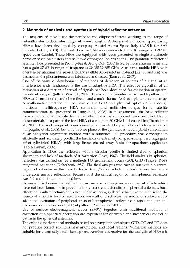
has been reduced one can see the contribution of the diffraction field from the edges of the reflector. According to the field distribution shown at fig.1 a feed of the spherical reflector can consist
of set of discrete sources disposed from paraxial focus 0,5z = to apex of the reflector 1z = .
The separate discrete source illuminates a part of ring on the aperture limited by the beams unitary reflected from concave surface of the reflector.
Fig. 1. Distribution of the electrical field component xE along axes of the spherical reflector
at the wave length 3,14 cmλ = : thick line corresponds to curvature radius of the reflector
100a cm= ; thin line - 50a cm= ; points - 25a cm=
The results of the investigation of hemispherical reflector antenna with radius of curvature
2 3a m= at frequency 11,2 GHz , are discussed (Tingye, 1959). At the excitation of the
central path of the reflector with diameter 1,1 m phase errors at the aperture were less
than 8π , SLL of the pattern were less -25 dB.
Using the channel waveguides as a corrected line source of the spherical antennas seems to
be an effective way to reduce the phase errors at the aperture of a spherical reflector (Love,
1962). This line corrected source guarantees the required distribution of the field with
illuminated edges of the reflector at the sector of 70c and guarantees electromechanical
scattering of the pattern over sector of 110c . An array of waveguide slot sources with
dielectric elements for correcting the amplitude-phase field distribution along aperture can
be used as the line feed source (Spencer et al., 1949).
Integral equations method is the effective way to solve the problem of spherical aberration
correction for reflector with any electrical radius (Elsherbeni, 1989), but at the same time it
has difficult physical interpretation of the results and the accuracy is not guaranteed. In
theory and practice of correction of spherical aberration is considered within the limits of
central area aperture where rays are unitary reflected from concave surface. The edges areas
of aperture are not considered for illumination. However, when an incident wave falls on
hemispherical reflector, surface EMW propagate along its concave surface. The amplitude of
surface waves is concentrated in thin layer with width r λΔ ≈ that is bordered with the
reflecting surface. Using the amplitude stability of surface EMW with respect to surface
curvature is very important for spherical aberration correction for reflectors with 2 180θ = c .
www.intechopen.com
The Analysis of Hybrid Reflector Antennas and Diffraction Antenna Arrays on the Basis of Surfaces with a Circular Profile
289
3.3 Solve of Maxwell’s equations in spherical coordinates and diffraction problems It is known that diffraction on concave bodies gives a series of effects, which are still not practically used for improving electrical characteristics of spherical reflector antennas. These are the effects of multiple reflections and the effect of “whispering gallery”, that show themselves when the source of electromagnetic field is disposed near the reflector.
Solves of wave equation about electrical field in the spherical coordinates ( , , )r θ ϕ with using a
group of rotates 1 2 ( )E E iEϕ θ+ = − + , 0 rE E= , 1 2 ( )E E iEϕ θ− = − will look as series of
cylindrical *( )lf r and spherical functions , 2( , ,0)l
m nT π ϕ θ− (Gradshteyn & Ryzhik, 2000)
00 , 0 2
0
, 1 20
, 1 20
( , , ) ( ) ( , ,0)
( , , ) ( ) ( , ,0)
( , , ) ( ) ( , ,0)
ll
l l n nl n l
ll
l l n nl n l
ll
l l n nl n l
E r f r T
E r f r T
E r f r T
π
π
π
θ ϕ α ϕ θθ ϕ β ϕ θθ ϕ γ ϕ θ
∞= =−∞ ++ = =−∞ −− −= =−
⎫= − ⎪⎪⎪⎪= − ⎬⎪⎪⎪= − ⎪⎭
∑ ∑∑ ∑∑ ∑
,
where , , ,, ,l n l n l nα β γ - weighting coefficients. Taking into consideration the generalized spherical functions over joined associated
Legendre functions 1(cos )lP θ and polynomial Jacobi (0,2)1 (cos )lP θ− , common solving of wave
equation about components of electrical field can be written as follows
( ) ( )
( ) ( ) ( ) ( )
( ) ( )
/21/2 13/2
1
21 /23/2 1/2 0,2
11/2 3/2
1/21/22 0,2
2 11/21
( )(cos ) ;
cos ( ) ( )2 ( 1) (cos )1 cos ( 1)
2( )1 cos
sin (cos ) ;2 2
ilr l l
l
il ll
lil
ll
J krE A P e
kr
lC J kr J kr
l P ei l l kr krE
J krli C P e
kr
π ϕ
π ϕθ
π ϕ
θπ
θθθ π θ
∞ − −+=
− −+ + −∞∞= − −+ −=
=
⎡ ⎤⎢ ⎥− + ++ ⎢ ⎥+ ⎣ ⎦=++
∑
∑∑
( ) ( ) ( )
( ) ( )
2
/23/2 1/2 0,21 11/2 3/2
1/21/22 0,2
2 11/21
sin ( ) ( )2 ( 1) (cos )( 1)1 cos
2( )1 cos
cos (cos ) .2 2
il ll
lil
ll
lJ kr J kr
C l P el l kr krE
J krlC P e
kr
π ϕϕ
π ϕ
πθθ
θ π θ
− −+ + −∞∞= − −+ −=
⎫⎪⎪⎪⎪⎪⎪⎪⎪⎪⎪⎪⎪⎬⎪⎪⎪⎪⎪⎡ ⎤ ⎪⎢ ⎥− + −⎪⎢ ⎥++ ⎪⎣ ⎦= − ⎪+ ⎪− ⎪⎪⎭
∑∑
, (1)
where 1 2, ,lA C C are the constant coefficients.
The analysis of the equations (1) shows that eigenwaves propagate into hemisphere with
angles θ± . Each wave propagates with its constant of propagation ( )m nγ along virtual curves
www.intechopen.com

Wave Propagation
290
with radiuses ( ) ( ) /m n m nr kγ= with maintaining vectors of polarization about component rE
and Eϕ (fig.2). In the area near points ( ) ( ) /m n m nr kγ= the aperture of reflector is coordinated
with surrounding space under conditions of eigenwaves propagation.
Fig. 2. Waves propagation in to hemispherical reflector
The amplitude of the electrical field strength vector Ef
with arbitrary angle ϕ is defined as
2 2rE E Eϕ= +f
,
where ( ) ( )2 2Re Imr r rE E E= + ; ( ) ( )2 2
Re ImE E Eϕ ϕ ϕ= + ;
( )( )3/2Re ( ) ( )cos / 2 cosm mr m
m
E kr A J krγ γ γ θ π ϕ−= − ⋅∑ ;
( )( )3/2Im ( ) ( )sin / 2 cosm mr m
m
E kr A J krγ γ γ θ π ϕ−= − ⋅∑ ;
( ) ( )( )1
1/2 3/2
( ) ( )Re 1 / 2 cos / 2 sin
( ) ( )
n n
n n nn
J kr J krE A
kr kr
γ γϕ γ γ γ θ π ϕ+⎡ ⎤= − + × − ⋅⎢ ⎥⎢ ⎥⎣ ⎦∑ ;
( ) ( )( )1
1/2 3/2
( ) ( )Im 1 / 2 sin / 2 sin
( ) ( )
n n
n n nn
J kr J krE A
kr kr
γ γϕ γ γ γ θ π ϕ+⎡ ⎤= − + × − ⋅⎢ ⎥⎢ ⎥⎣ ⎦∑ ;
1 1
0 0
1 1 11 ( ) ( ) 1 ( ) ( )
2 2n n nn
ka ka
n n
dz dzA F z J z F z J z
N z zγ γ γγ γ γ+ −
⎡ ⎤⎛ ⎞ ⎛ ⎞⎢ ⎥= − + +⎜ ⎟ ⎜ ⎟⎜ ⎟ ⎜ ⎟⎢ ⎥⎝ ⎠ ⎝ ⎠⎣ ⎦∫ ∫ ;
1/2
0
1( ) ( )
m mm
ka
A F z z J z dzN
γ γγ= ∫ ;
2
0
( )m m
ka
N J z dzγ γ⎡ ⎤= ⎣ ⎦∫ ;
2 22 2
1 1
0 0
1 11 ( ) 1 ( )
2 2n n n
ka ka
n n
dz dzN J z J z
z zγ γ γγ γ+ −
⎛ ⎞ ⎛ ⎞⎡ ⎤ ⎡ ⎤= − − +⎜ ⎟ ⎜ ⎟⎜ ⎟ ⎜ ⎟⎣ ⎦ ⎣ ⎦⎝ ⎠ ⎝ ⎠∫ ∫ ; ( )F z is
the given distribution of the field on the aperture of a hemispherical reflector.
www.intechopen.com
The Analysis of Hybrid Reflector Antennas and Diffraction Antenna Arrays on the Basis of Surfaces with a Circular Profile
291
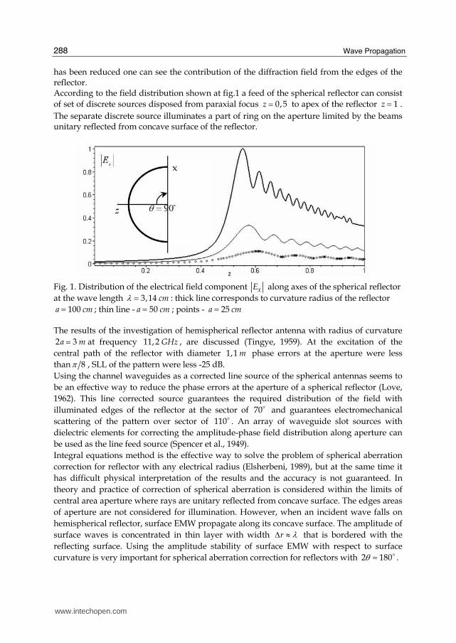
The distribution of electric field on the surface of virtual polarized cone inside hemispherical
reflector with electrical radius of curvature 40ka = and uniform distribution of incident
field on the aperture ( ) ( ) 1F z F kr= = has two powerful interferential maximums. First
maximum is placed near paraxial focus from 10kr = to 30kr = , second maximum is placed
near reflected surface kr ka= (fig.3). It is possible to observe the redistribution of
interferential maximums along radial axes on a virtual cone by increasing the angle value of
the cone.
Fig. 3. Distribution of the electric field on the surface of virtual polarization cone with angle
value 2Θ = c (a) and 10Θ = c (b)
Obviously the feed of hemispherical reflector presented as set of discrete sources that must be placed at the polarized cone according to a structure of power lines and amplitude-phase distribution of the field. According to distribution of electromagnetic field along radial axes on the arbitrary section (fig.3), the line phased feed can consist of discrete elements. It is obvious that this phased feed have an advantage about absence a shadow region of aperture. According to increase cone value Θ of polarized cone is decrease an efficiency of excitation the aperture.
Focusing properties of the edge areas of the hemispherical reflector are displayed when
solving the problem of excitation a perfect electric conducting spherical surface by the
symmetrical ring of electric current with coordinates ( , )kr θ′ ′ , where sin 1.kr θ′ ′ >> The ring
of electric current is equivalent to double magnetic sheet with thickness d with density of
electrostatic charge σ± for neighboring sheets (fig.4). Let us define scalar Green function of the problem ( , , , )Г Г kr krθ θ′ ′= as a function
satisfactory to homogeneous wave equation anywhere, except the ring current, where electrostatic potential dη σ= ⋅ exposes a jump that equivalent the condition:
0 04 4 ( )kr kr krθ θ θ θθ θ πη π δ′ ′= + = − ′∂Γ ∂ − ∂Γ ∂ = − = − − . Let us search Green function
satisfactory to radiation condition lim 0r
Гr ikrГ
r→∞∂⎛ ⎞− =⎜ ⎟∂⎝ ⎠ and boundary condition
( )3/2 0z ka
z z Г =∂ ∂ = as
13/2
2 1
(cos ) (cos ),( ) ( )8sin
( 1) ( ) (cos ) (cos ),( )
( )
m mm m
m m mm
m
m mm
L PJ kr J krkrГka kr J ka L P
J kakr
ν νγ γγ ν νγ
θ θ θ θγπ θ ν ν θ θ θ θγ
⎧ ⎫′ ′>′′− ⎛ ⎞ ⎪ ⎪′= × × ⎨ ⎬⎜ ⎟ + ∂⎝ ⎠ ′ ′<⎪ ⎪⎩ ⎭∂ ∂∑ , (2)
www.intechopen.com

Wave Propagation
292
where 1 12
(cos ) (cos ) (cos )m m m
L Q i Pπν ν νθ θ θ= + ; 1 / 2m mν γ= − ; 1 (cos )m
Qν θ - associated
Legendre functions of the 2-nd kind.
Fig. 4. Geometry of excitation of hemispherical reflector by electric current ring
Consider one-connected area D on complex surface γ and distinguish points 1 2, ,..., mγ γ γ
for this surface as solutions of Neumann boundary condition for Green function. In every
point of the area D function Г is univalent analytic function, except points 1 2, ,..., mγ γ γ
where it has simple poles. Let us place the field source on the concave hemisphere surface
( )kr ka′ = . Using Cauchy expression present (2) as a sum of waves and integral with contour
that encloses part of the poles γ , satisfactory to the condition 1/3ka ka kaγ< < − and
describing the geometrical optic rays field. In the distance from axis of symmetry
( 1)mγ θ >> , the contour integral is given as
{ }0
1/2 [( 1/2)( ) /2] ( 1/2)( )3/2
1/2
( )2 sin
sin ( )( )
i i
C
J krkae e d
J kakr
ν ν θ θ π ν θ θν
θ νθ + ′ ′+ + + ± + −+
′− +′∫ .
The sign “+” at index exponent corresponds for θ θ ′> and the sign “–“ for θ θ ′< . A factor 1/2(sin /sin )θ θ′ explains geometrical value of increasing of rays by double concave of the
hemispherical reflector with comparison to cylindrical surface. First component in contour
integral correspond a brighten point at the distance part of the ring with electrical current,
second component – brighten point at the near part of the ring. Additional phase /2π is
interlinked with passing of rays through the axis caustic.
In the focal point area ( 1)mγ θ ≤ the contour integral can be written as
0
1/2 1/2 21/2 [( 1/2) 1/4]
13/21/2
( )4( / 2) ( ) sin ( 1 / 2)(( 1 / 2) )
sin ( )( 1)( )
i
C
J krkaJ e d
J kakr
ν ν θν
π θ θ ν ν θ νθ ν ν+ ′+ ++
′− + + ′+∫ .
In accordance with a stationary phase method the amplitude and phase structure of the field in tubes of the rays near a caustic can be investigated.
The distribution of the radial component of the electrical field rE along axis of the
hemisphere with radius of curvature 22,5a cm= for uniform distribution field on the
aperture / 2θ π= has two powerful interferential maximums at the wave length
6,28cmλ = (dotted line), 2,513cmλ = (thin line) and 0,838cmλ = (thick line) (fig.5).
……
……
rk ′σ− σ+
0−′θ0+′θ
rkf
0
θθ ′ka
d
x
z
www.intechopen.com

The Analysis of Hybrid Reflector Antennas and Diffraction Antenna Arrays on the Basis of Surfaces with a Circular Profile
293
First maximum is near paraxial focus / 2F ka= and is caused by diffraction of the rays,
reflected from concave surface at the central area of the reflector. Second interferential maximum characterizes diffraction properties of the edges of hemispherical reflector. In this area the rays test multiple reflections from concave surface and influenced by the “whispering gallery” waves.
At decrease the wavelength λ first diffraction maximum is displaced near a paraxial focus
10F cm= , a field at the area r f< is decreasing quickly as well as the wavelength. Second
diffraction maximum is narrow at decrease of the wavelength, one can see redistribution of the interferential maximums near paraxial focus.
Fig. 5. Diffraction properties of the hemisphere dish with radius of curvature 22,5a cm=
In accordance with the distribution of the field, a spherical antenna can have a feed that
consists of two elements: central feed in the area near paraxial focus and additional feed
near concave surface hemisphere. This additional feed illuminates the edge areas of aperture
by surface EMW. The use of additional feed can increase the gain of the spherical antennas.
3.4 Experimental investigations of spherical hybrid antenna Accordingly a fig.5, the feed of the spherical HRA can consist of two sections. First section is
ordinary feed as line source arrays that place near paraxial focus. Second section is
additional feed near concave spherical surface and consists of four microstrip or waveguide
sources of the surface EMW. An aperture of the additional feed must be placed as near as
possible to longitudinal axis of the reflector. The direction of excitation of the additional
sources is twice-opposite in two perpendicular planes. This compound feed of the spherical
reflector can control the amplitude and phase distribution at the aperture of the spherical
antenna.
Extended method of spherical aberration correction shows that additional sources of surface
EMW must be presented as the aperture of rectangular waveguides or as microstrip sources
with illumination directions along the reflector at the opposite directions. By phasing of the
additional and main sources and by choosing their amplitude distribution one can control
SLL of the pattern and increase the gain of the spherical antenna.
www.intechopen.com
Wave Propagation
294
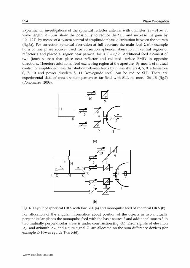
Experimental investigations of the spherical reflector antenna with diameter 2 31a cm= at
wave length 3cmλ = show the possibility to reduce the SLL and increase the gain by
10 12%− by means of a system control of amplitude-phase distribution between the sources
(fig.6a). For correction spherical aberration at full aperture the main feed 2 (for example
horn or line phase source) used for correction spherical aberration in central region of
reflector 1 and placed at region near paraxial focus / 2F a= . Additional feed 3 consist of
two (four) sources that place near reflector and radiated surface EMW in opposite
directions. Therefore additional feed excite ring region at the aperture. By means of mutual
control of amplitude-phase distribution between feeds by phase shifters 4, 5, 9, attenuators
6, 7, 10 and power dividers 8, 11 (waveguide tees), can be reduce SLL. There are
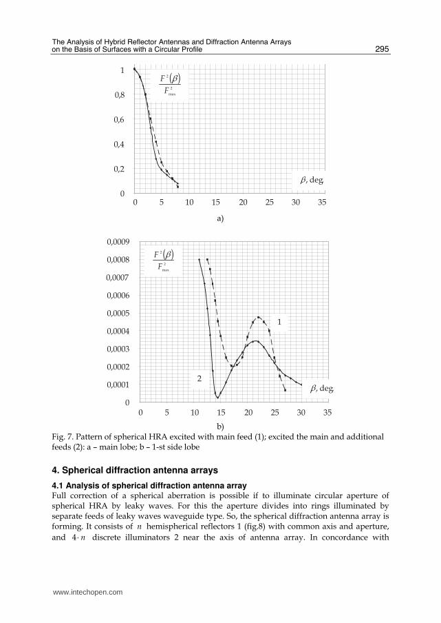
experimental data of measurement pattern at far-field with SLL no more -36 dB (fig.7)
(Ponomarev, 2008).
(a)
(b)
Fig. 6. Layout of spherical HRA with low SLL (a) and monopulse feed of spherical HRA (b)
For allocation of the angular information about position of the objects in two mutually
perpendicular planes the monopulse feed with the basic source 2 and additional souses 3 in
two mutually perpendicular areas is under construction (fig. 6b). Error signals of elevation
εΔ and azimuth βΔ and a sum signal Σ are allocated on the sum-difference devices (for
example E- H-waveguide T-hybrid).
ϕ
ϕ
E
H ϕϕ
ϕ
HH
H
E Δ
1
9
23
βΔΣ
εΔβΣ εΣ
10
46
7 5
ϕϕϕ
ϕϕ
ϕ
ϕ
8
ϕ11
32
1
46
57
910
www.intechopen.com
The Analysis of Hybrid Reflector Antennas and Diffraction Antenna Arrays on the Basis of Surfaces with a Circular Profile
295
0
0,2
0,4
0,6
0,8
1
( )2
max
2
F
F β
.deg,β
1
8,0
6,0
4,0
2,0
00 5 10 15 20 25 30 35
a)
0
0,0001
0,0002
0,0003
0,0004
0,0005
0,0006
0,0007
0,0008
0,0009
0 5 10 15 20 25 30 35
( )2
max
2
F
F β
.deg,β2
1
0009,0
0008,0
0007,0
0006,0
0005,0
0004,0
0003,0
0002,0
0001,0
00 5 10 15 20 25 30 35
b)
Fig. 7. Pattern of spherical HRA excited with main feed (1); excited the main and additional feeds (2): a – main lobe; b – 1-st side lobe
4. Spherical diffraction antenna arrays
4.1 Analysis of spherical diffraction antenna array Full correction of a spherical aberration is possible if to illuminate circular aperture of spherical HRA by leaky waves. For this the aperture divides into rings illuminated by separate feeds of leaky waves waveguide type. So, the spherical diffraction antenna array is forming. It consists of n hemispherical reflectors 1 (fig.8) with common axis and aperture,
and 4 n⋅ discrete illuminators 2 near the axis of antenna array. In concordance with
www.intechopen.com

Wave Propagation
296
electrodynamics the spherical diffraction antenna array consists of diffraction elements wich are formed by two neighbouring hemispherical reflectors and illuminated by four sources. For illuminate the diffraction element between the correcting reflectors there illuminators are located in cross planes.
Fig. 8. Spherical diffraction antenna array: 1 – hemispherical reflectors; 2 – linear phased feed
The feed sources illuminated waves waveguide type between hemispherical reflectors
which propagate along reflecting surfaces and illuminated all aperture of antenna. By means
of change of amplitude-phase field distribution between feed sources the amplitude and a
phase of leaky waves and amplitude-phase field distribution on aperture are controlled. For
maximized of efficiency and gain of antenna the active elements should place as close as it is
possible to an antenna axis. At the expense of illuminating of diffraction elements of HRA
by leaky waves feeds their phase centers are “transforms” to the aperture in opposite points.
Thus the realization of a phase method of direction finding in HRA is possible.
The eigenfunctions/GTD – method is selected due to its high versatility for analyzing the characteristics of diffraction antenna arrays with arbitrary electrical curvature of reflectors.
Let's assume that in diffraction element there are waves of electric and magnetic types. Let
for the first diffraction element the relation of radiuses of reflectors is 1M Ma a −Δ = . In
spherical coordinates ( )1 ;M Mr a a−∈ , ( )0; / 2θ π∈ , ( )0;ϕ π∈ according to a boundary
problem of diffraction of EMW on ring aperture of diffraction element, an electrical
potential U satisfies the homogeneous equation of Helmholtz
( ) ( )2, , , , 0r k U rθ ϕ θ ϕΔ + =
and boundary conditions of the 1-st kind
1;
0M Mr a r a
U −= = = (3)
or 2-nd kind
1;
0
M Mr a r a
U
r −= =∂ =∂ (4)
1
2
2
www.intechopen.com
The Analysis of Hybrid Reflector Antennas and Diffraction Antenna Arrays on the Basis of Surfaces with a Circular Profile
297
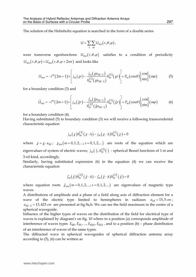
The solution of the Helmholtz equation is searched in the form of a double series
( ), ,mss m
U U r θ ϕ=∑∑ ,
were transverse egenfunctions ( ), ,msU r θ ϕ satisfies to a condition of periodicity
( ) ( ), , , , 2ms msU r U r nθ ϕ θ ϕ π= + and looks like
( ) ( ) ( )( ) ( ) ( ) ( ) ( ) ( )11
11
cos2 1 cos
sinm Mm
ms m m m
m M
j gaU i m j gr h gr P m
h gaθ ϕ−
−
⎡ ⎤ ⎧ ⎫⎪ ⎪⎢ ⎥= − + × − × ⎨ ⎬⎢ ⎥ ⎪ ⎪⎩ ⎭⎣ ⎦ (5)
for a boundary condition (3) and
( ) ( ) ( )( ) ( ) ( ) ( ) ( ) ( )11
11
cos2 1 cos
sinm Mm
ms m m m
m M
j gaU i m j gr h gr P m
h gaθ ϕ−
−
⎡ ⎤′ ⎧ ⎫⎪ ⎪⎢ ⎥= − + × − × ⎨ ⎬′⎢ ⎥ ⎪ ⎪⎩ ⎭⎣ ⎦## # ##
(6)
for a boundary condition (4). Having substituted (5) to boundary condition (3) we will receive a following transcendental
characteristic equation
( ) ( ) ( ) ( ) ( ) ( )1 10m m m mj h j hχ χ χ χ⋅ Δ − ⋅ Δ =
where Mg aχ = ⋅ ; ( )0,1,2,...; 0,1,2,...ms m sχ = = are roots of the equation which are
eigenvalues of system of electric waves; ( ) ( )(1),m mj h⋅ ⋅ - spherical Bessel functions of 1-st and
3-rd kind, accordingly.
Similarly, having substituted expression (6) in the equation (4) we can receive the
characteristic equation
( ) ( ) ( ) ( ) ( ) ( )1 10m m m mj h j hχ χ χ χ′ ′′ ′⋅ Δ − ⋅ Δ =# # # #
where equation roots ( )0,1,2,...; 0,1,2,...ms m sχ = =# are eigenvalues of magnetic type
waves.
A distributions of amplitude and a phase of a field along axis of diffraction element for a
wave of the electric type limited to hemispheres in radiuses 15,5Ma cm= ;
1 13,423Ma cm− = are presented at fig.9a,b. We can see the field maximum in the centre of a
spherical waveguide. Influence of the higher types of waves on the distribution of the field for electrical type of
waves is explained by diagram’s on fig. 10 where to a position (a) corresponds amplitude of
interference of waves types 00 01 010 011, , ..., ,E E E E , and to a position (b) – phase distribution
of an interference of waves of the same types.
The diffracted wave in spherical waveguides of spherical diffraction antenna array
according to (5), (6) can be written as
www.intechopen.com

Wave Propagation
298
а) b)
Fig. 9. Distribution of amplitude (a) and phase (b) of fundamental mode E00 of spherical waveguide
а) b)
Fig. 10. Distribution of amplitude (a) and phase (b) of eleven electrical type eigenwaves ( )0 1,2,...,11sE s =
( ) ( ) ( )( ) ( ) ( ) ( ) ( ) ( )11/2
1, 1
cos2 1 cos
sinm Mim
ms m m mm s m M
j gaU e m j gr h gr P m
h ga
π θ ϕ−−−
⎡ ⎤Ω ⎧ ⎫⎪ ⎪⎢ ⎥= + − × ⎨ ⎬⎢ ⎥ ⎪ ⎪⎩ ⎭Ω⎣ ⎦∑ , (7)
where ( )1
d
d gr
⎧ ⎫⎪ ⎪Ω = ⎨ ⎬⎪ ⎪⎩ ⎭.
Asymptotic expression for msU at 1 1Mga − >> looks as
( ) ( )2 2
11/3
1 1/42 2
1
1 12
exp 12
2
3exp arccos exp arccos
2 21 s
M
ms M
M
s M Ms si
s
i k r a
U ka
g r a
C a ai i
r re π γ
π
π πγ θ γ θ
−−
−− −⋅ ⋅
⎡ ⎤⎛ ⎞⋅ − +⎜ ⎟⎢ ⎥⎝ ⎠⎣ ⎦→ ×−
⎧ ⎫⎡ ⎤ ⎡ ⎤⎛ ⎞ ⎛ ⎞⎪ ⎪× − − + − −⎨ ⎬⎢ ⎥ ⎢ ⎥⎜ ⎟ ⎜ ⎟− ⎝ ⎠ ⎝ ⎠⎪ ⎪⎣ ⎦ ⎣ ⎦⎩ ⎭∑ (8)
where sC - amplitudes of "creeping" waves (Keller, 1958); sγ - poles of 1-st order for (7).
∑=
11
1
0
i
iU
r, cm
.
'
Re
Im
11
1
0
11
1
0
rad
U
U
arctg
i
i
i
i
⎟⎠⎞⎜⎝
⎛⎟⎠⎞⎜⎝
⎛
∑∑=
=
r, cm
www.intechopen.com
The Analysis of Hybrid Reflector Antennas and Diffraction Antenna Arrays on the Basis of Surfaces with a Circular Profile
299
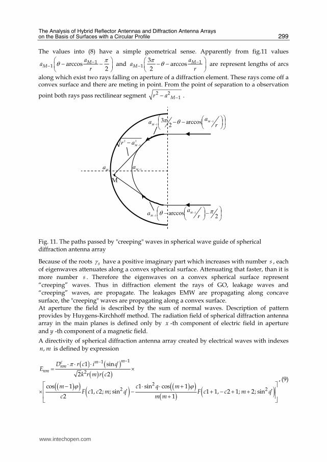
The values into (8) have a simple geometrical sense. Apparently from fig.11 values
11 arccos
2M
Ma
ar
πθ −− ⎛ ⎞− −⎜ ⎟⎝ ⎠ and 11
3arccos
2M
Ma
ar
π θ −− ⎛ ⎞− −⎜ ⎟⎝ ⎠ are represent lengths of arcs
along which exist two rays falling on aperture of a diffraction element. These rays come off a convex surface and there are meting in point. From the point of separation to a observation
point both rays pass rectilinear segment 2 21Mr a −− .
Fig. 11. The paths passed by "creeping" waves in spherical wave guide of spherical diffraction antenna array
Because of the roots sγ have a positive imaginary part which increases with number s , each
of eigenwaves attenuates along a convex spherical surface. Attenuating that faster, than it is
more number s . Therefore the eigenwaves on a convex spherical surface represent
“creeping” waves. Thus in diffraction element the rays of GO, leakage waves and
“creeping” waves, are propagate. The leakages EMW are propagating along concave
surface, the "creeping" waves are propagating along a convex surface. At aperture the field is described by the sum of normal waves. Description of pattern provides by Huygens-Kirchhoff method. The radiation field of spherical diffraction antenna array in the main planes is defined only by x -th component of electric field in aperture
and y -th component of a magnetic field.
A directivity of spherical diffraction antenna array created by electrical waves with indexes
,n m is defined by expression
( ) ( )( ) ( )( )( ) ( ) ( )( )( ) ( )
11
2
22 2
1 sin
2 2
cos 1 1 sin cos 11, 2; ; sin 1 1, 2 1; 2; sin
2 1
mc mnm
nm
D r c i qE
k r m r c
m c q mF c c m q F c c m q
c m m
π
ϕ ϕ
−− ′⋅ ⋅ ⋅= ×⎡ ⎤− ⋅ ⋅ +⎢ ⎥′ ′× − + − + +⎢ ⎥+⎣ ⎦
, (9)
M
Ma 1−M
a
2
1
2
−−M
ar
⎟⎠⎞⎜⎝
⎛ ⎟⎠⎞⎜⎝⎛−− −− ra
a M
M
1
1arccos
23 θπ
⎟⎠⎞⎜⎝
⎛ −⎟⎠⎞⎜⎝⎛− −− 2arccos 1
1
πθr
aa M
M
www.intechopen.com

Wave Propagation
300
where cnmD - weight coefficients; ( ) ( )2 1, ; ; , ; ;F a b x z F a b x z= - hypergeometric functions;
( )1 0,5 2nc mν= + − ; ( )2 0,5 2nc mν= − + ; nν - propagation constants of electrical type
eigenwaves; ,q ϕ′ ′ - observation point coordinates at far-field.
For magnetic types of waves
( ) ( )( ) ( )( )( ) ( ) ( )( )( ) ( )
11
2
22 2
2 3 sin
4
cos 1 3 sin cos 13, 4; ; sin 3 1, 4 1; 2; sin
4 1
ppsp
sps
W B r c i qE
w k r p r c
p c q pF c c p q F c c p q
c p p
π
ϕ ϕ
−− ′⋅ ⋅ ⋅ ⋅ ⋅= ×⎡ ⎤′ ′ ′− ⋅ ⋅ +⎢ ⎥′ ′× − + + − + +⎢ ⎥+⎣ ⎦
,(10)
where 0 0sE = for 0p = ; W - free space impedance; sw - propagation constants of
magnetic type eigenwaves; ( )3 0,5 2sc w p= + + ; ( )4 0,5 2sc w p= − − .
Generally the pattern of spherical diffraction antenna array consists of the partial characteristics enclosed each other created by electrical and magnetic types of waves that it is possible to present as follows
1 0 1 0
N N
nm spn m s p
E E E∞ ∞
= = = == +∑ ∑ ∑∑ , (11)
where nmE , spE - the partial patterns that defined by expressions (9), (10).
4.2 Numerical and experimental results
Numerical modeling by the (10) show that at 0q = in a direction of main lobe, the far-field
produced only by waves with azimuthally indexes 1m = , 1p = . At 0q > the fare-field
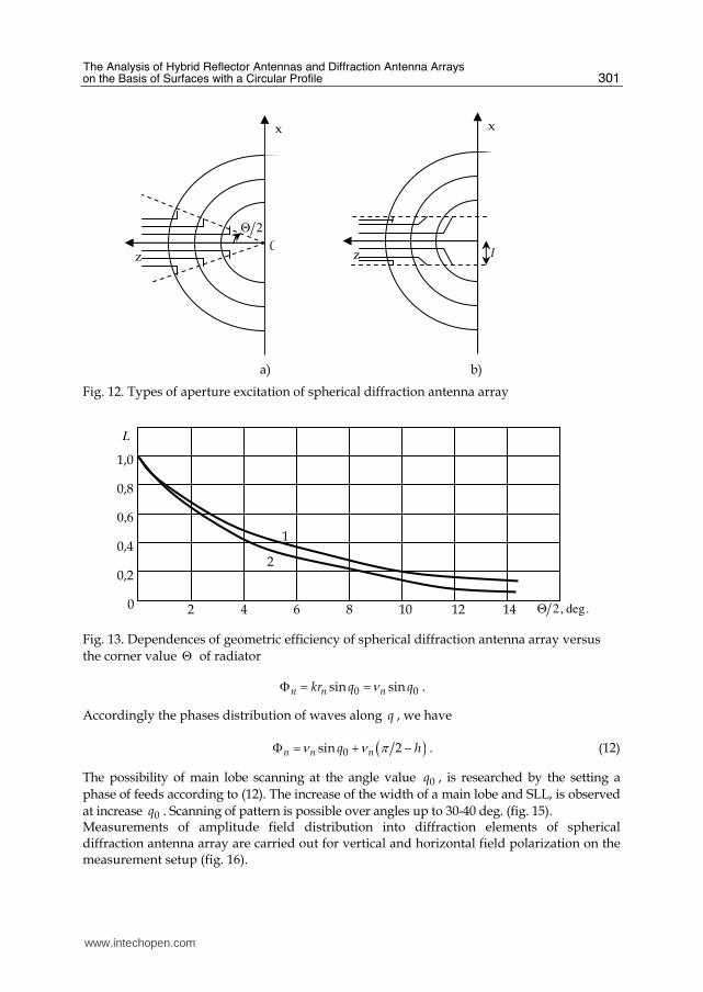
created by EMW with indexes 0 m< < ∞ , 0 p< < ∞ . Influence of location of feeds to field distribution on aperture of spherical diffraction antenna array, is researched. At the first way feeds took places on an imaginary surface of a polarization cone (fig. 12а). On the second way feeds took places on equal distances from an axis of the main reflector (fig. 12b).
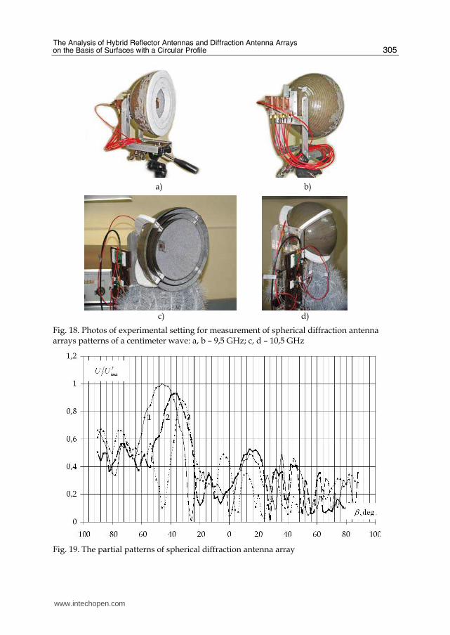
Dependences of geometric efficiency of antenna 0L S S= ( 0S - square of radiated part of
antenna, S - square of aperture) versus the corner value Θ at the identical sizes of radiators
for the first way (a curve 1) and the second way (a curve 2), are shown on fig.13.
Dependences of directivity versus the corner value Θ , are presented on fig.14. Growth of
directivity accordingly reduction the value Θ explain the focusing properties of reflectors of
diffraction elements. Most strongly these properties appear at small values of Θ . The rise of
directivity is accompanied by equivalent reduction of width of main lobe on the plane yoz .
A comparison with equivalent linear phased array is shown that in spherical diffraction
antenna array the increasing of directivity at 4-5 times, can be achieved.
For scanning of pattern over angle 0q it is necessary to realize linear change of a phase on
aperture by the expression 0sinkr qΦ = . As leakage waveguide modes excited between
correcting reflectors, possess properties to transfer phase centers of sources for scanning of
pattern over angle 0q , it is necessary that a phase of the feeds allocated between reflectors in
radiuses na , 1na + , are defines by
www.intechopen.com
The Analysis of Hybrid Reflector Antennas and Diffraction Antenna Arrays on the Basis of Surfaces with a Circular Profile
301
а) b)
Fig. 12. Types of aperture excitation of spherical diffraction antenna array
Fig. 13. Dependences of geometric efficiency of spherical diffraction antenna array versus
the corner value Θ of radiator
0 0sin sinn n nkr q qνΦ = = .
Accordingly the phases distribution of waves along q , we have
( )0sin 2n n nq hν ν πΦ = + − . (12)
The possibility of main lobe scanning at the angle value 0q , is researched by the setting a
phase of feeds according to (12). The increase of the width of a main lobe and SLL, is observed
at increase 0q . Scanning of pattern is possible over angles up to 30-40 deg. (fig. 15). Measurements of amplitude field distribution into diffraction elements of spherical diffraction antenna array are carried out for vertical and horizontal field polarization on the measurement setup (fig. 16).
z
x
2Θ0
z
x
l
0
0,4
0,6
0,2
0,8
1,0
2 4 6 8 10 12 14
1
2
.deg,2Θ
L
www.intechopen.com

Wave Propagation
302
Fig. 14. Dependences of directivity versus the corner value Θ of radiator
Fig. 15. Dependence of amplitude of the main lobe of spherical diffraction antenna array versus the scanning angle
Far-field and near-field properties of the aforementioned antennas were measured using the
compact antenna test range facilities at the antenna laboratory of the Baltic Fishing Fleet
State Academy. The experimental setting of spherical diffraction antenna array consists of
two diffraction elements 1 that forms by reflectors with radiuses 1 9,15a = cm, 2 10,7a = cm
and 3 12,6a = cm. The spherical diffraction antenna array aperture was illuminated from far
zone (15 m) by vertically polarized field. The 4λ probe which was central conductor of a
coaxial cable at diameter of 2 mm, was used. It moved on the carriage 3 of positioning
system QLZ 80 (BAHR Modultechnik GmbH). The output of a probe through cable
assemble SM86FEP/11N/11SMA (4) with the length 50 cm (HUBER+SUHNER AG)
connected with the low noise power amplifier HMC441LP3 (Hittite MW Corp.) (5) with gain
equal 14 dB. The amplifier output through cable assembles SM86FEP/11N/11SMA
0
40
80
120
160D
irec
tiv
ity
10 20 30 40 50 .deg,2Θ
00=q
0
0,2
0,4
0,6
0,8
1,0
1,2
10 20 30 40 50
c20=ΘE
.deg,0
q
www.intechopen.com

The Analysis of Hybrid Reflector Antennas and Diffraction Antenna Arrays on the Basis of Surfaces with a Circular Profile
303
connected to programmed detector section HMC611LP3 (6). Its output connected to digital
multimeter. For selection of traveling waves into diffraction elements, the half of aperture
was closed by radio absorber.
Fig. 16. Photos of experimental setting for measurement of amplitude field distribution inside the diffraction elements of spherical diffraction antenna array
During measurement of a radial component of the electrical field rE along axis of spherical
diffraction antenna array the bottom half of aperture was closed by the radio absorber (at
vertical polarization of incident waves), and during measurement of a tangential component
of the electrical field Eϕ the left half of aperture was closed by it. The amplitude distribution
of the tangential component of electric field Eϕ along axis of spherical diffraction antenna
array at the frequency 10 GHz is presented on fig. 17.
Fig. 17. Normalized amplitude distribution of the tangential component of electric field Eϕ
along axis of spherical diffraction antenna array at the frequency 10 GHz: 1 – measured, 2 –
calculated by suggested method
www.intechopen.com

Wave Propagation
304
The experimental measurements of partial patterns of spherical diffraction antenna array in
a centimeter waves are carried out. The feed of spherical diffraction antenna array is
fabricated on series 0,813 mm-thick substrates Rogers RO4003C with permittivity 3,35. The
feeds consist of the packaged microstrip antennas tuned on the frequencies range 10 GHz.
The technique of designing and an experimental research of packaged feeds of spherical
diffraction antenna arrays include following stages: definition of geometrical characteristics
of feeds (subject to radial sizes of diffraction elements and amplitude-phase distribution
inside diffraction elements at the set polarization of field radiation); optimization of
geometrical parameters of microstrip antennas, power dividers, feeding lines (subject to
influence of metal walls of diffraction element); an experimental investigation of S-
parameters of a feeds; computer optimization of a feeds geometry in Ansoft HFSS.
Experimental measurements of spherical diffraction antenna array were by a method of the
rotate antenna under test in far-field zone subject to errors of measurements. At 8-11 GHz
frequency range the partial patterns were measured at linear polarization of incident waves.
The reflectors and the radiator are adjusted at measurement setting (fig.18).
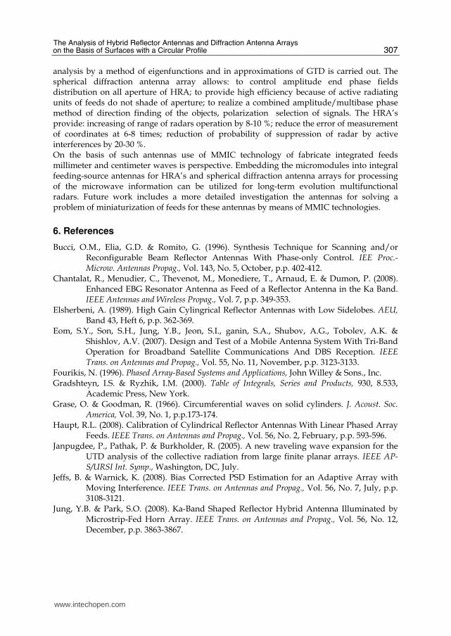
The form and position of patterns of spherical diffraction antenna array for one side of
package feed characterize electrodynamics properties of diffraction elements and edge
effects of multireflector system (fig.19). The distances of partial patterns with respect to
phase centre of the antenna were: for 1-st (greatest) diffraction element – 46c (curve 1), for
2-nd diffraction element – 38c (curve 2), for 3-rd diffraction element – 32c (curve 3). The
radiuses of reflectors: 1 12,6a = cm, 2 9,79a = cm, 3 7,89a = cm and 4 6,28a = cm.
The comparative analysis of measurements results of spherical diffraction antenna array
partial patterns shows possibility of design multibeam antenna systems with a combination
of direction finding methods (amplitude and phase), of frequency ranges and of radiation
(reception) field polarization. The angular rating of partial patterns can be used the spherical
diffraction antenna arrays as feeds for big size HRA’s or planar antenna arrays ( )100 1000n n λ⋅ − ⋅ . The diffraction elements isolation defines a possibility of creating a multifrequency
diffraction antenna arrays in which every diffraction element works on the fixed frequency
in the set band. Besides, every diffraction element of spherical diffraction antenna arrays is
isolated on polarization of the radiation (reception) field. Such antennas can be used as
frequency-selective and polarization-selective devices.
The usage spherical diffraction antenna arrays as angular sensors of multifunctional radars of the purpose and the guidance weapon are effective.
As a rule, antenna systems surface-mounted and on board phase radars consist of four
parabolic antennas with the common edges (fig. 20a) for direction finding of objects in two
ortogonal planes. In the centre of antenna system the rod-shaped dielectric antenna forming
wide beam of pattern can dispose. At attempt of reduction of the aperture size of antenna
system D∗ the distance between the phase centers of antennas becomes less then diameter
of a reflector b D< . The principle of matching of a slope of direction finding characteristics
to width of area of unequivocal direction finding is broken. Alternative the considered antenna system of phase radar is the antenna consisting of one
reflector and a radiator exciting opposite areas of aperture the surface EMW that
propagating directly along a concave hemispherical reflector (fig. 20b).
www.intechopen.com
The Analysis of Hybrid Reflector Antennas and Diffraction Antenna Arrays on the Basis of Surfaces with a Circular Profile
305
a) b)
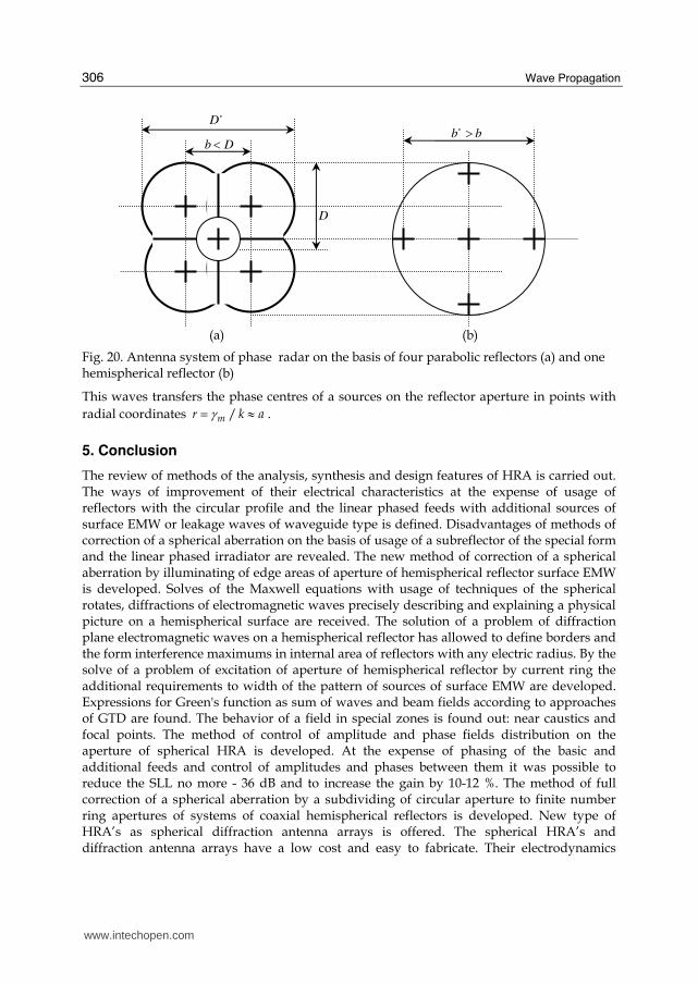
c) d)
Fig. 18. Photos of experimental setting for measurement of spherical diffraction antenna arrays patterns of a centimeter wave: a, b – 9,5 GHz; c, d – 10,5 GHz
Fig. 19. The partial patterns of spherical diffraction antenna array
www.intechopen.com
Wave Propagation
306
(a) (b)
Fig. 20. Antenna system of phase radar on the basis of four parabolic reflectors (a) and one hemispherical reflector (b)
This waves transfers the phase centres of a sources on the reflector aperture in points with
radial coordinates /mr k aγ= ≈ .
5. Conclusion
The review of methods of the analysis, synthesis and design features of HRA is carried out. The ways of improvement of their electrical characteristics at the expense of usage of reflectors with the circular profile and the linear phased feeds with additional sources of surface EMW or leakage waves of waveguide type is defined. Disadvantages of methods of correction of a spherical aberration on the basis of usage of a subreflector of the special form and the linear phased irradiator are revealed. The new method of correction of a spherical aberration by illuminating of edge areas of aperture of hemispherical reflector surface EMW is developed. Solves of the Maxwell equations with usage of techniques of the spherical rotates, diffractions of electromagnetic waves precisely describing and explaining a physical picture on a hemispherical surface are received. The solution of a problem of diffraction plane electromagnetic waves on a hemispherical reflector has allowed to define borders and the form interference maximums in internal area of reflectors with any electric radius. By the solve of a problem of excitation of aperture of hemispherical reflector by current ring the additional requirements to width of the pattern of sources of surface EMW are developed. Expressions for Green's function as sum of waves and beam fields according to approaches of GTD are found. The behavior of a field in special zones is found out: near caustics and focal points. The method of control of amplitude and phase fields distribution on the aperture of spherical HRA is developed. At the expense of phasing of the basic and additional feeds and control of amplitudes and phases between them it was possible to reduce the SLL no more - 36 dB and to increase the gain by 10-12 %. The method of full correction of a spherical aberration by a subdividing of circular aperture to finite number ring apertures of systems of coaxial hemispherical reflectors is developed. New type of HRA’s as spherical diffraction antenna arrays is offered. The spherical HRA’s and diffraction antenna arrays have a low cost and easy to fabricate. Their electrodynamics
Db <∗
D
D
bb >∗
www.intechopen.com
The Analysis of Hybrid Reflector Antennas and Diffraction Antenna Arrays on the Basis of Surfaces with a Circular Profile
307
analysis by a method of eigenfunctions and in approximations of GTD is carried out. The spherical diffraction antenna array allows: to control amplitude end phase fields distribution on all aperture of HRA; to provide high efficiency because of active radiating units of feeds do not shade of aperture; to realize a combined amplitude/multibase phase method of direction finding of the objects, polarization selection of signals. The HRA’s provide: increasing of range of radars operation by 8-10 %; reduce the error of measurement of coordinates at 6-8 times; reduction of probability of suppression of radar by active interferences by 20-30 %. On the basis of such antennas use of MMIC technology of fabricate integrated feeds millimeter and centimeter waves is perspective. Embedding the micromodules into integral feeding-source antennas for HRA’s and spherical diffraction antenna arrays for processing of the microwave information can be utilized for long-term evolution multifunctional radars. Future work includes a more detailed investigation the antennas for solving a problem of miniaturization of feeds for these antennas by means of MMIC technologies.
6. References
Bucci, O.M., Elia, G.D. & Romito, G. (1996). Synthesis Technique for Scanning and/or Reconfigurable Beam Reflector Antennas With Phase-only Control. IEE Proc.-Microw. Antennas Propag., Vol. 143, No. 5, October, p.p. 402-412.
Chantalat, R., Menudier, C., Thevenot, M., Monediere, T., Arnaud, E. & Dumon, P. (2008). Enhanced EBG Resonator Antenna as Feed of a Reflector Antenna in the Ka Band. IEEE Antennas and Wireless Propag., Vol. 7, p.p. 349-353.
Elsherbeni, A. (1989). High Gain Cylingrical Reflector Antennas with Low Sidelobes. AEU, Band 43, Heft 6, p.p. 362-369.
Eom, S.Y., Son, S.H., Jung, Y.B., Jeon, S.I., ganin, S.A., Shubov, A.G., Tobolev, A.K. & Shishlov, A.V. (2007). Design and Test of a Mobile Antenna System With Tri-Band Operation for Broadband Satellite Communications And DBS Reception. IEEE Trans. on Antennas and Propag., Vol. 55, No. 11, November, p.p. 3123-3133.
Fourikis, N. (1996). Phased Array-Based Systems and Applications, John Willey & Sons., Inc. Gradshteyn, I.S. & Ryzhik, I.M. (2000). Table of Integrals, Series and Products, 930, 8.533,
Academic Press, New York. Grase, O. & Goodman, R. (1966). Circumferential waves on solid cylinders. J. Acoust. Soc.
America, Vol. 39, No. 1, p.p.173-174. Haupt, R.L. (2008). Calibration of Cylindrical Reflector Antennas With Linear Phased Array
Feeds. IEEE Trans. on Antennas and Propag., Vol. 56, No. 2, February, p.p. 593-596. Janpugdee, P., Pathak, P. & Burkholder, R. (2005). A new traveling wave expansion for the
UTD analysis of the collective radiation from large finite planar arrays. IEEE AP-S/URSI Int. Symp., Washington, DC, July.
Jeffs, B. & Warnick, K. (2008). Bias Corrected PSD Estimation for an Adaptive Array with Moving Interference. IEEE Trans. on Antennas and Propag., Vol. 56, No. 7, July, p.p. 3108-3121.
Jung, Y.B. & Park, S.O. (2008). Ka-Band Shaped Reflector Hybrid Antenna Illuminated by Microstrip-Fed Horn Array. IEEE Trans. on Antennas and Propag., Vol. 56, No. 12, December, p.p. 3863-3867.
www.intechopen.com
Wave Propagation
308
Jung, Y.B., Shishlov, A. & Park, S.O. (2009). Cassegrain Antenna With Hybrid Beam Steering Scheme for Mobile Satellite Communications. IEEE Trans. on Antennas and Propag., Vol. 57, No. 5, May, p.p. 1367-1372.
Keller, J. (1958). A geometrical theory of diffraction. Calculus of variations and its applications. Proc. Symposia Appl. Math., 8, 27-52. Mc Graw-Hill., N.Y.
Llombart, N., Neto, A., Gerini, G., Bonnedal, M. & Peter De Maagt. (2008). Leaky Wave Enhanced Feed Arrays for the Improvement of the Edge of Coverage Gain in Multibeam Reflector Antennas. IEEE Trans. on Antennas and Propag., Vol. 56, No. 5, May, p.p. 1280-1291.
Love, A. (1962). Spherical Reflecting Antennas with Corrected Line Sources. IRE Trans. on Antennas and Propagation, Vol. AP-10, September, No. 5-6, p.p.529-537.
Miller, M. & Talanov, V. (1956). Electromagnetic Surface Waves Guided by a Boundary with Small Curvature. Zh. Tekh. Fiz, Vol. 26, No. 12, p.p. 2755-2765.
Ponomarev, O. (2008). Diffraction of Electromagnetic Waves by Concave Circumferential Surfaces: Application for Hybrid Reflector Antennas. Bull. of the Russian Academy of Sciences: Physics, Vol. 72, No. 12, p.p. 1666-1670.
Rayleigh, J.W.S. (1945). The Theory of Sound, 2-nd ed., Vol. 2, Sec. 287, Dover Publication, ISBN 0-486-60293-1, New York.
Schell, A. (1963). The Diffraction Theory of Large-Aperture Sp-herical Reflector Antennas. IRE Trans. on Antennas and Propagation, July, p.p. 428-432.
Shevchenko, V. (1971). Radiation losses in bent waveguides for surface waves. Institute of Radioengineering and Electronics, Academy of Sciences of the USSR. Translated from Izvestiya Vysshikh Uchebnykh Zavedenii, Radiofizika, Vol. 14, No. 5, p.p. 768-777, May.
Spencer, R., Sletten, C. & Walsh, J. (1949). Correction of Spherical Aberration by a Phased Line Source. Proc. N.E.C., Vol. 5, p.p. 320-333.
Tap, K. & Pathak, P.H. (2006). A Fast Hybrid Asymptotic and Numerical Physical Optics Analysis of Very Large Scanning Cylindrical Reflectors With Stacked Linear Array Feeds. IEEE Trans. on Antennas and Propag., Vol. 54, No. 4, April, p.p. 1142-1151.
Tingye, L. (1959). A Study of Spherical Reflectors as Wide-Angle Scanning Antennas. IRE Trans. on Antennas and Propagation, July, p.p. 223-226.
www.intechopen.com

Wave PropagationEdited by Dr. Andrey Petrin
ISBN 978-953-307-275-3Hard cover, 570 pagesPublisher InTechPublished online 16, March, 2011Published in print edition March, 2011
InTech EuropeUniversity Campus STeP Ri Slavka Krautzeka 83/A 51000 Rijeka, Croatia Phone: +385 (51) 770 447 Fax: +385 (51) 686 166www.intechopen.com
InTech ChinaUnit 405, Office Block, Hotel Equatorial Shanghai No.65, Yan An Road (West), Shanghai, 200040, China
Phone: +86-21-62489820 Fax: +86-21-62489821
The book collects original and innovative research studies of the experienced and actively working scientists inthe field of wave propagation which produced new methods in this area of research and obtained new andimportant results. Every chapter of this book is the result of the authors achieved in the particular field ofresearch. The themes of the studies vary from investigation on modern applications such as metamaterials,photonic crystals and nanofocusing of light to the traditional engineering applications of electrodynamics suchas antennas, waveguides and radar investigations.
How to referenceIn order to correctly reference this scholarly work, feel free to copy and paste the following:
Oleg Ponomarev (2011). The Analysis of Hybrid Reflector Antennas and Diffraction Antenna Arrays on theBasis of Surfaces with a Circular Profile, Wave Propagation, Dr. Andrey Petrin (Ed.), ISBN: 978-953-307-275-3, InTech, Available from: http://www.intechopen.com/books/wave-propagation/the-analysis-of-hybrid-reflector-antennas-and-diffraction-antenna-arrays-on-the-basis-of-surfaces-wi