ska specifications and reflector antennas p. dewdney mar 31, 2008
Post on 18-Dec-2015
249 views
TRANSCRIPT
SKA Specifications andReflector Antennas
P. DewdneyMar 31, 2008
SPDOOutline
1. SKA Top-Level Specifications.
2. Potential Implementations for Low-Mid Frequency SKA (Phase 2).
3. Implications for reflector antenna design.
4. Snapshot of current antenna design activity.
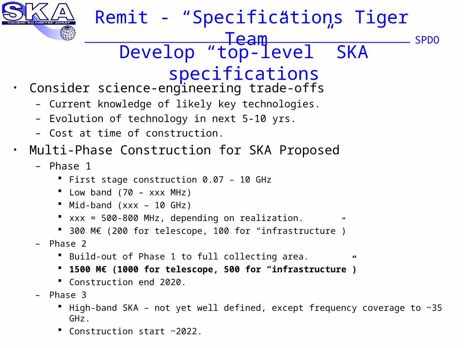
SPDORemit - “Specifications Tiger Team”
• Consider science-engineering trade-offs– Current knowledge of likely key technologies.– Evolution of technology in next 5-10 yrs.– Cost at time of construction.
• Multi-Phase Construction for SKA Proposed– Phase 1
First stage construction 0.07 – 10 GHz Low band (70 – xxx MHz) Mid-band (xxx – 10 GHz) xxx = 500-800 MHz, depending on realization. 300 M€ (200 for telescope, 100 for “infrastructure”)
– Phase 2 Build-out of Phase 1 to full collecting area. 1500 M€ (1000 for telescope, 500 for “infrastructure”) Construction end 2020.
– Phase 3 High-band SKA – not yet well defined, except frequency coverage to ~35 GHz. Construction start ~2022.
Develop “top-level” SKA specifications
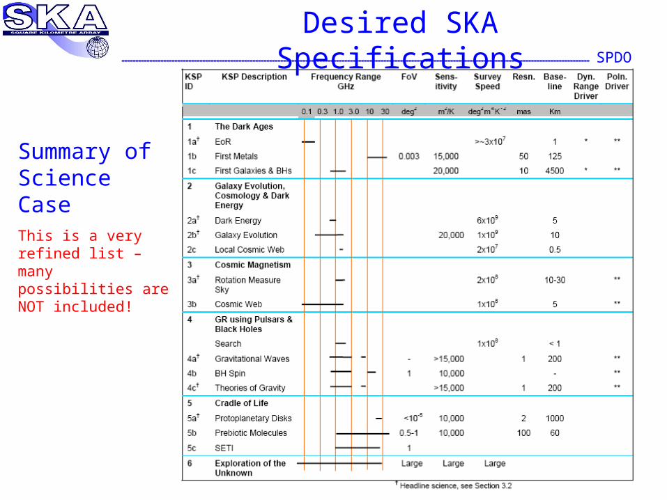
SPDODesired SKA Specifications
Summary of Science CaseThis is a very refined list – many possibilities are NOT included!
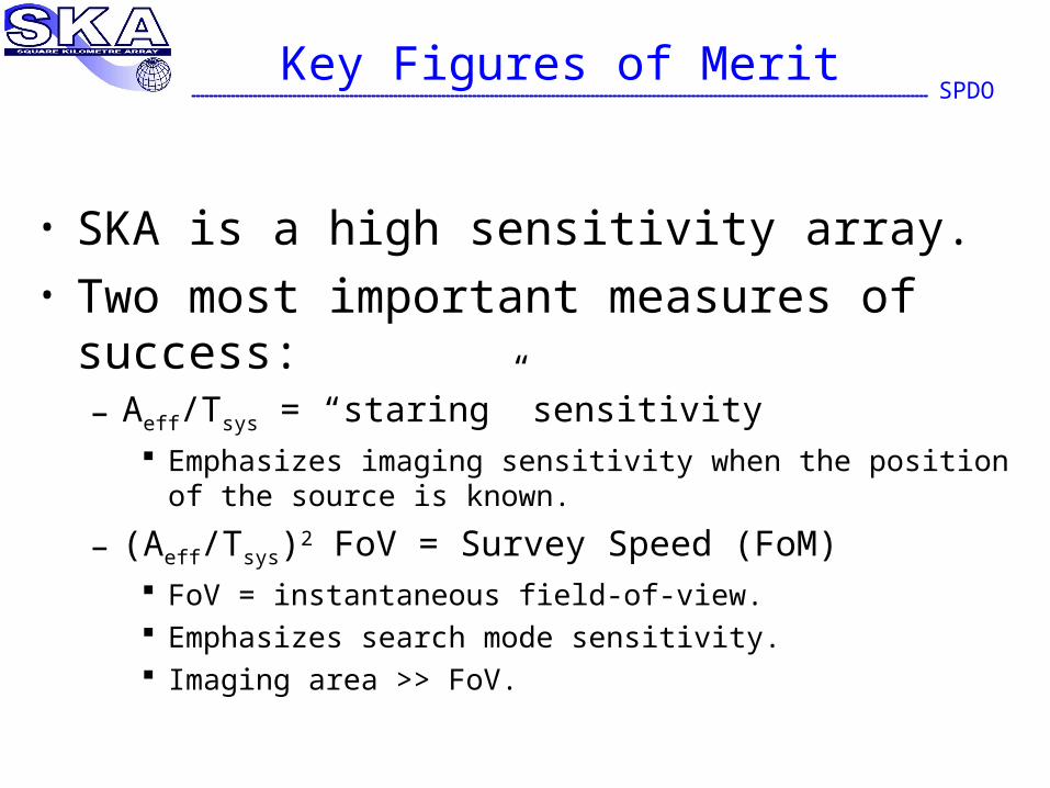
SPDOKey Figures of Merit
• SKA is a high sensitivity array.• Two most important measures of success:
– Aeff/Tsys = “staring” sensitivity Emphasizes imaging sensitivity when the position of the source
is known.
– (Aeff/Tsys)2 FoV = Survey Speed (FoM) FoV = instantaneous field-of-view. Emphasizes search mode sensitivity. Imaging area >> FoV.
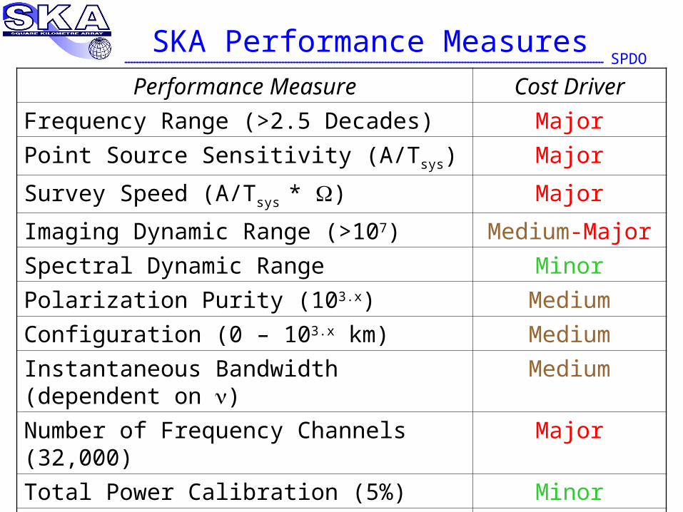
SPDOSKA Performance Measures
Performance Measure Cost Driver
Frequency Range (>2.5 Decades) Major
Point Source Sensitivity (A/Tsys) Major
Survey Speed (A/Tsys * ) Major
Imaging Dynamic Range (>107) Medium-Major
Spectral Dynamic Range Minor
Polarization Purity (103.x) Medium
Configuration (0 – 103.x km) Medium
Instantaneous Bandwidth (dependent on ) Medium
Number of Frequency Channels (32,000) Major
Total Power Calibration (5%) Minor
Time-domain Capabilities (transients, pulsars) Minor
Sky Coverage Medium
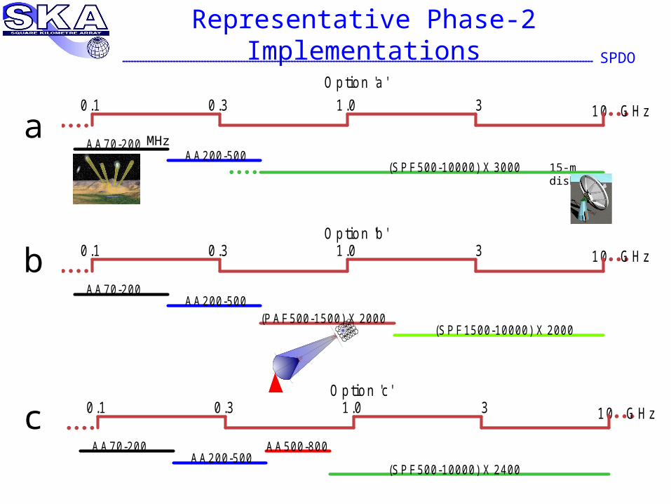
SPDORepresentative Phase-2 Implementations
a
b
c
15-m dishes
0 .1 0 .3 1 .0 3 10
AA70-200AA200-500
(SPF1500-10000) X 2000(PAF500-1500) X 2000
GHz
0.1 0 .3 1 .0 3 10
AA70-200AA200-500
(SPF500-10000) X 3000
GHz
Option 'a '
0 .1 0 .3 1 .0 3 10
AA70-200AA200-500
AA500-800
(SPF500-10000) X 2400
GHz
Option 'b '
Op tion 'c '
MHz
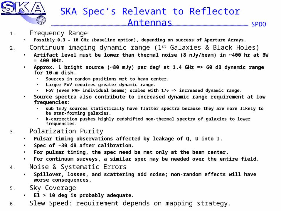
SPDOSKA Spec’s Relevant to Reflector Antennas
1. Frequency Range• Possibly 0.3 – 10 GHz (baseline option), depending on success of Aperture Arrays.
2. Continuum imaging dynamic range (1st Galaxies & Black Holes)• Artifact level must be lower than thermal noise (8 nJy/beam) in ~400 hr at BW
= 400 MHz.• Approx. 1 bright source (~80 mJy) per deg2 at 1.4 GHz => 60 dB dynamic
range for 10-m dish.• Sources in random positions wrt to beam center.• Larger FoV requires greater dynamic range.• FoV (even PAF individual beams) scales with 1/ => increased dynamic range.
• Source spectra also contribute to increased dynamic range requirement at low frequencies:• sub 1mJy sources statistically have flatter spectra because they are more likely to be
star-forming galaxies.• k-correction pushes highly redshifted non-thermal spectra of galaxies to lower
frequencies.
3. Polarization Purity• Pulsar timing observations affected by leakage of Q, U into I.• Spec of –30 dB after calibration.• For pulsar timing, the spec need be met only at the beam center.• For continuum surveys, a similar spec may be needed over the entire field.
4. Noise & Systematic Errors• Spillover, losses, and scattering add noise; non-random effects will have
worse consequences.
5. Sky Coverage• El > 10 deg is probably adequate.
6. Slew Speed: requirement depends on mapping strategy.
SPDOSKA Spec’s Flow-down to Antennas
1. Frequency range• Diameter sufficient to meet dynamic range specs at 300
MHz.• Low spillover of primary and/or secondary.
• Optical configuration may have to include both prime and secondary foci.
2. Polarization Purity• Many of the dynamic range issues also apply to
polarization.• See next slide.
• Feed design will be the strongest influence.• Offset antennas have polarization pattern when fed from
the prime focus.• Effect can be cancelled at the beam center with a secondary
reflector.
SPDOSpec’s Flow-down (cont’d)
3. Imaging dynamic range• Stability of polar diagram on sky – rotation on sky is a subject of
debate.• Stability of polar diagram on ground – very small time-variable signals.
• Can’t have it stable on the ground and on the sky.
• “Recovered” Pointing Error• Strong sources near ½ power point very sensitive to pointing (P 0.72
[/FWHM] for Gaussian).• For P < 10-6, 1.4 X 10⁻⁶ FWHM.• Clearly this “spec” cannot be met without recovery of pointing from the
data.• Self-calibration, mosaicing and other “averaging” techniques will be
necessary to effectively recover pointing errors (e.g. see Perley, Synthesis Imaging in RA, 1999).
• System modelling and testing with existing telescopes will be needed.• “Working spec” of 0.01 FWHM at 10 GHz might be reasonable for now.
• Scattering• Feed leg and focus box scattering.• Surface imperfections.• Rotating or varying scattering patterns on the sky will likely be a major
problem.
• Sidelobes• Even perfect diffraction sidelobes will be difficult to handle if they vary
against the sky.• PAF’s offer a chance to optimize feed pattern to reduce sidelobes while
maintaining good efficiency at low frequencies.
SPDORemarks on Antenna Spec’s
• We can’t afford poor-quality antennas.• The cost of mitigating the effects of uncorrected errors
induced by antenna imperfections could be larger than the cost of making the antennas better.
• Careful modelling and simulations will be needed to understand this better.
• We may have a choice between “sky-mount” and clear-aperture antennas.
• How do we investigate this choice?• Clear-aperture antennas might be allowed to rotate against
the sky.• Can polar patterns be made sufficiently symmetrical or
with known asymmetry?
SPDORole of Pathfinders is Critical
• Provides basis for building antennas in medium quantities– Justifies expenditure on medium-scale production
technology. Apply the “1, 10, 100” concept.
– Provides a means of assessing subtle areas of performance, especially dynamic range. Sufficiently large array is necessary to obtain sensitive
tests.
• Important that Pathfinders provide scope for innovation– High enough quality to be able to meet SKA specs.– Scope for design and production R&D.
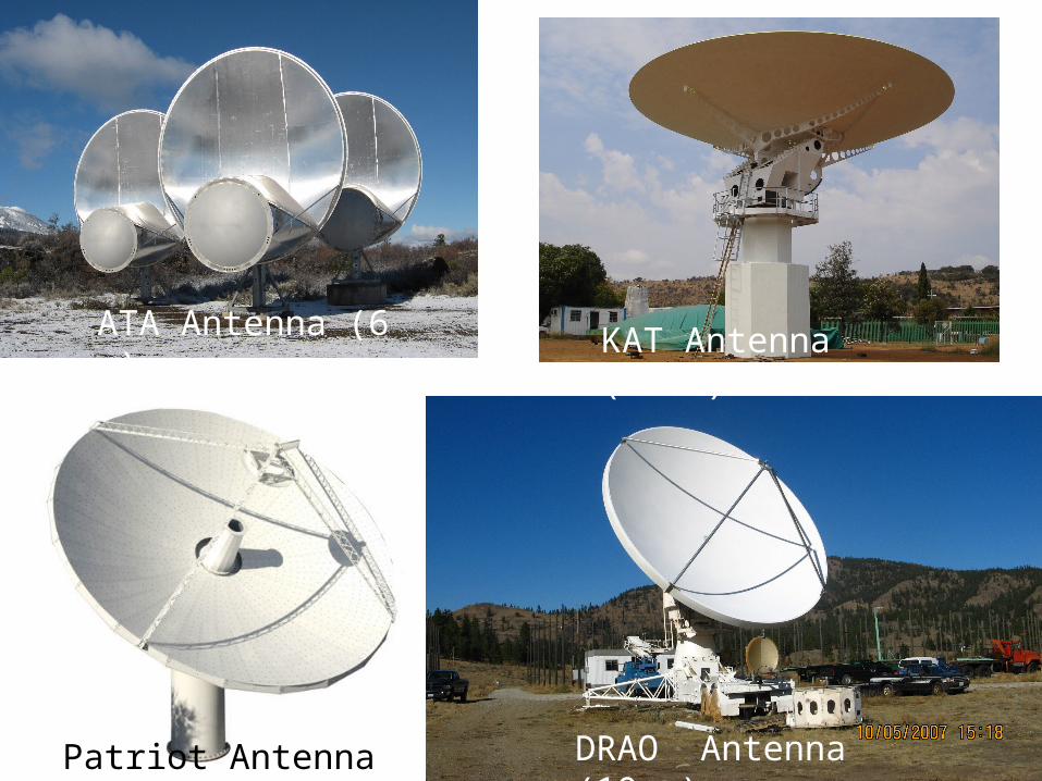
Patriot Antenna (12 m)
ATA Antenna (6 m) KAT Antenna (15 m)
DRAO Antenna (10 m)
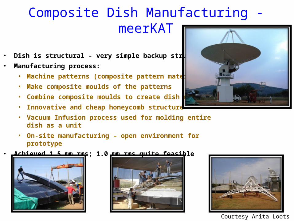
Composite Dish Manufacturing - meerKAT
• Dish is structural - very simple backup structure
• Manufacturing process:
• Machine patterns (composite pattern material)
• Make composite moulds of the patterns
• Combine composite moulds to create dish mould
• Innovative and cheap honeycomb structure
• Vacuum Infusion process used for molding entire dish as a unit
• On-site manufacturing – open environment for prototype
• Achieved 1.5 mm rms; 1.0 mm rms quite feasible
Courtesy Anita Loots
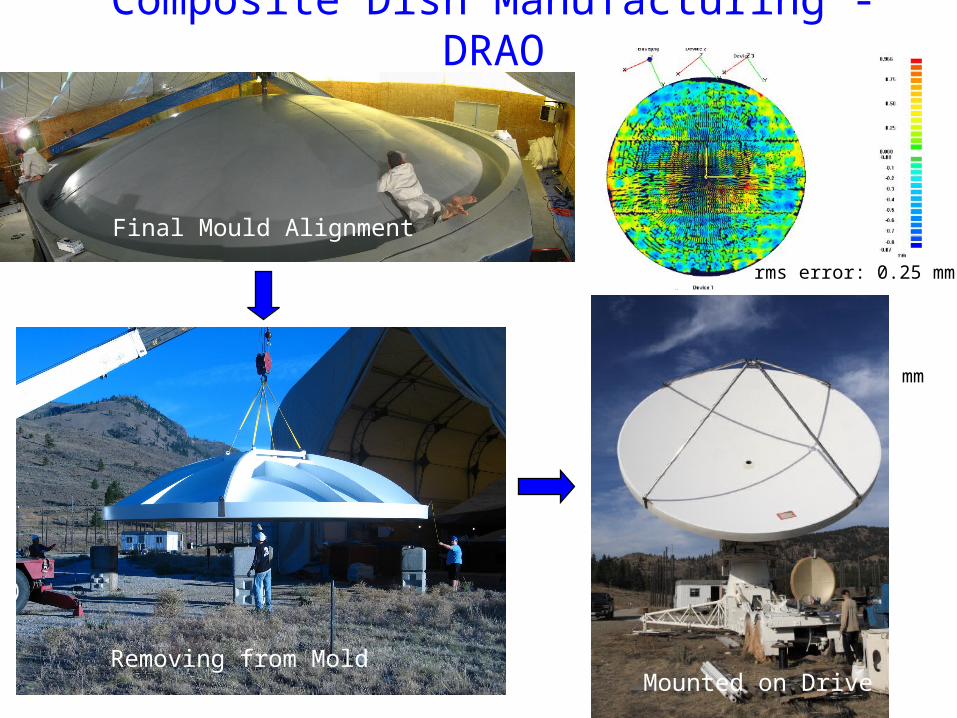
rms error: 0.25 mm
Final Mould Alignment
Composite Dish Manufacturing - DRAO
Removing from MoldMounted on Drive
rms error: 0.25 mm
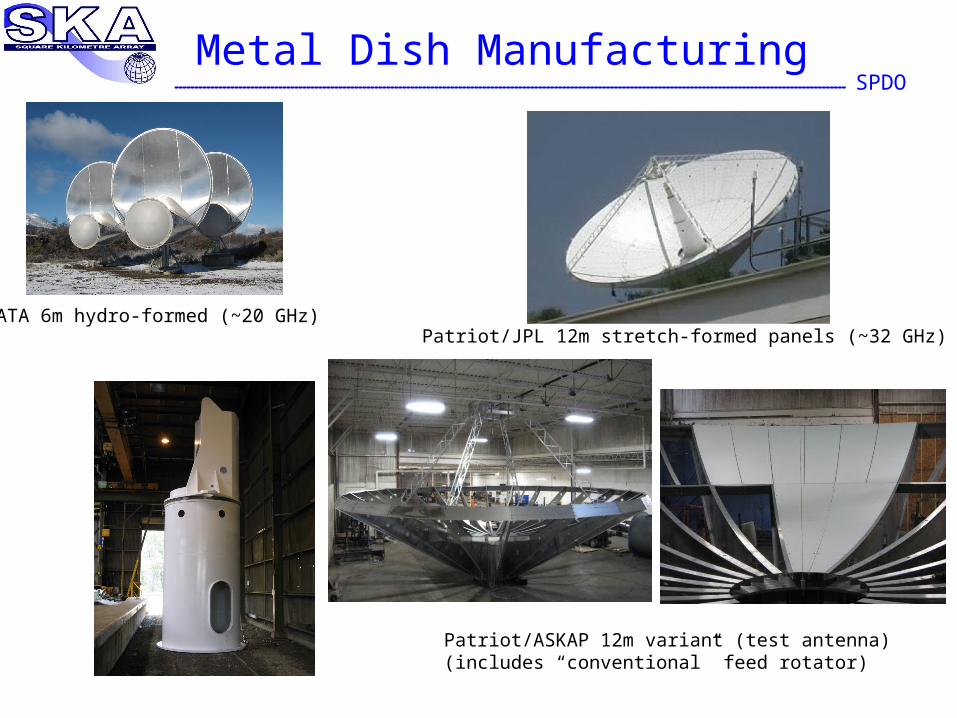
SPDOMetal Dish Manufacturing
ATA 6m hydro-formed (~20 GHz)
Patriot/ASKAP 12m variant (test antenna)(includes “conventional” feed rotator)
Patriot/JPL 12m stretch-formed panels (~32 GHz)
SPDOConsiderations for TDP Antenna Development
• Parameterized antenna model suitable for insertion into an end-to-end model of the SKA.
– help refine antenna spec’s.
• Develop a refined antenna cost model.• Set up system for field evaluation of antennas
– Basic measurements – pointing, slewing, etc. T from 5C to 55C in 2 hours, sun shining on one side of
dish.– Wind distortion.
• Build antenna on VLA site – to carry out tests with VLA.
Dynamic range, imaging, calibration, etc.
• Wide-band feed/rcvr refinements and testing.

SPDO
End