testing 10 gb/s sonet/sdh equipment and components
TRANSCRIPT

Testing 10 Gb/sSONET/SDH equipment
and components
71612C 12.5 Gb/serror performance analyzer
Product NoteProduct NoteProduct NoteProduct NoteProduct Note
2
Contents
Introduction .............................................................................................................. 3
– The serial BERT in the synchronous era ............................................................. 3
Typical applications ............................................................................................... 4
– Creation and real-time editing of custom patterns ........................................... 5– Pattern stores .......................................................................................................... 6– Setting and editing an STS-192
SONET-compatible pattern ................................................................................... 7
Testing 10 Gb/s SONET/SDH equipment and components ............................... 11
– Pseudo-dynamic testing with alternating patterns .......................................... 11– SONET/SDH system test with user-programmable patterns ......................... 11– Error location analysis ............................................................................................ 13

3
Introduction
This document describes key features of the 71612C 12.5 Gb/s errorperformance analyzer that are particularly beneficial in thedevelopment and production testing of components and sub-systemsfor SONET/SDH transmission equipment. The creation and real-timeediting of custom patterns up to 8 Mbits in length using the 71612Canalyzer’s pattern editor are described. The examples shown areSONET patterns, however the techniques and measurementsdescribed are equally applicable to SDH systems.
Potential applications for the 71612C analyzer in SONET/SDHcomponent and system test are identified.
An error location analysis option is available on the 71612C analyzer;this document shows how this may be used to measure thebit error ratio (BER) of a selected block of bits and any specific bit inthe pattern being generated. Then, it describes how the 71612Canalyzer can assist in the identification of systematic errors byindicating the position of each errored bit in turn and automaticallymeasuring the BER of each errored bit.
A demonstration disk, supplied with the 71612C analyzer, containssome of the patterns described in this document together with otheruseful patterns.
The serial BERT in thesynchronous era
Although telecommunications has moved into the SONET/SDH erawith its layered or structured signal architecture, the bit error ratiotest set (BERT) consisting of a serial pattern generator and erroranalyzer remains an essential tool in the R&D of communicationsystems, high-speed integrated circuits (ICs) and photoniccomponents. A fundamental reason for this is the requirement tocompare the theoretical and relative performance of systems andcomponents using a pseudo-random binary sequence (PRBS). ThePRBS is a suitable repetitive test signal that resembles a randomsignal, occurs in a mathematically predictable sequence and is easilygenerated by a shift register. This allows comparison of bitstransmitted from the BERT pattern generator with those received bythe error analyzer at the output of the device under test.
In addition to a range of industry standard PRBS patterns up to231 − 1 bits in length, the 71612C analyzer has over 8 Mbits (223) ofuser-programmable pattern memory that allow the creation ofcomplex custom test patterns for testing SONET/SDH systems andcomponents. A pattern containing up to six identical or differentSTS-192/STM-64 frames may be constructed, thus allowingfunctional (pseudo-dynamic) and alarm testing to be carried out. Theuser-programmable memory also allows framed and unframedpatterns to be constructed that stress timing recovery circuits,lightwave transmitters and receivers or, for example, induce baselinewander for margin testing.

4
Typical applications
Although the emphasis of this document is on the construction ofcomplex custom patterns compatible with SONET/SDH operationalequipment, the list below shows some of the tests routinely carriedout on the constituent components of such equipment.
l Pattern dependency testing (eg, ITU-T CID test).l Mean launch power (PRBS).l Eye diagram and mask analysis (PRBS).l Receiver sensitivity, eye contour measurements (PRBS).l Dynamic baseline wander testing (alternate programmable word).l Clock recovery circuit stress test (PRBS, variable mark and
transition density).l Regenerator test (PRBS).l IC tests (PRBS and word).
SONET/SDH signals contain regions within the data stream wherethe possibility of bit errors occurring is greater because of thesequence of data in these regions. This may be caused by eye closureresulting from dc wander; ac coupling causing the mean level of thesignal within the equipment to vary with pattern density; or failure ofthe timing recovery circuit to bridge regions of data that contain littletiming information in the form of transitions. The ITU-T have defineda test pattern to verify the adequacy of timing recovery and lowfrequency performance of STM-n equipment. This consists of a user-programmable pattern comprising consecutive blocks of data asfollows: The first row of section overhead bytes for the STM-n systemunder test, all ones (zero timing content, high average signalamplitude), pseudo-random data with 50% mark-density ratio, andthen a repeat of the overhead bytes, all zeros (zero timing content,low average signal amplitude) and the PRBS. For full details seeITU-T Recommendation G.958. The pattern is referred to as aconsecutive identical digit (CID) test pattern and is simplyconstructed with the 71612C analyzer’s pattern editor.
Alternating long patterns that induce a known amount of baselinewander for noise margin testing of decision circuits and regeneratorsmay also be programmed and generated with the 71612C analyzer. Inthe alternate pattern mode of operation it is possible to switchsynchronously between two different programmable patterns each ofwhich may be up to 4 Mbits in length.
Many SONET/SDH sub-systems and components are tested withPRBS patterns, however, to fully test a clock recovery IC requires theconstruction of variable transition ratio patterns with strongsub-harmonic content (for example, a repeating 11110000 patternhas a 25% transition density).

5
Creation and real-time editing ofcustom patterns
Figure 1. 71612C analyzer’s pattern editor
EditorUser
patternmemory
Output
Pattern stores
Pattern 1Pattern 2Pattern 3Pattern 4
(RAM)
Pattern 5Pattern 6Pattern 7Pattern 8DiskPatternsPattern 9Pattern 10Pattern 11Pattern 12
Save
Load
Figure 1 shows the relationship between the three main functionalblocks of the pattern editor: the editor, pattern stores and userpattern memory from which the instrument outputs a user pattern.The editor always edits the contents of the user pattern memory. Toedit one of the twelve patterns from the pattern stores, the contentsof the pattern store must first be loaded into the user patternmemory. It may then be edited and re-saved back to the patternstore.
The pattern editor supports the following operations:
l The contents of one of twelve pattern stores can be loaded intopattern memory, edited, saved and transmitted.
l Loading and editing of multiple copies of one of four fixed PRBS-based patterns in standard, zero substitution, or variable markdensity options (27, 210, 211 and 213).
l Copying of multiple copies of a pattern from one pattern storeinto a pattern at a precise point in the user pattern memory.
l Edit and display patterns in hexadecimal or binary notation.
l Saving of a marked block of bits within the user pattern memoryto an internal or disk pattern store; the deletion of a marked blockof bits.

6
Pattern stores
There are twelve pattern stores as follows:
l Pattern stores 1 to 4 can hold patterns up to 8 kbits in size (non-volatile RAM).
l Pattern stores 5 to 12 are held on the MS-DOS compatible floppydisk and can accommodate patterns of up to 8 Mbits in length inseparate files on the disk.
l The pattern currently stored in user pattern memory is accessedwith the <CURRENT PATTERN> softkey. This is the pattern that isgenerated when the user selects a user pattern as the activeoutput pattern.
When a user wishes to select a pattern store, a display similar to thatshown in figure 2 is shown on the screen. The information shown forpatterns 5 to 12 details the patterns stored on the currently accessi-ble disk which in the example shown includes patterns described inthe next section. Any one of the twelve user patterns may be recalledand edited either while a pattern other than a user pattern is beingoutput, or when the pattern to be edited is the active pattern cur-rently being output. In the latter case, real-time editing is possible.
Figure 2. Contents of pattern stores

7
Setting up and editing anSTS-192 SONET-compatiblepattern
The user creates a pattern by editing the contents of one of thepattern stores. As an example let us construct a 1,244,160 bit patternfor STS-192 applications with valid A1, A2 framing bytes, C1 bytes,and B1 and B2 section and line error monitoring bytes. The B1 andB2 bytes provide error monitoring by means of a bit-interleavedparity 8 code (BIP-8).
It is convenient to create this pattern on a blank high capacity diskthat has been formatted in the 71612C analyzer’s disk drive.
The ‘payload’ in the STS-192 frame will consist of the recommended27 − 1 scrambling sequence that starts with the 1111111 sequence. Toload multiple copies of this pattern into the STS-192 frame, the 27 − 1sequence must be stored in one of the pattern stores. The architec-ture of the pattern generator memory determines the length of thePRBS-based patterns that can be loaded into a user pattern by meansof the <LOAD BLOCK> feature. This includes a 27 pattern but not therequired 27 − 1 pattern. This is only a minor inconvenience; we select(for example) disk pattern store 5 for editing, set the pattern lengthto 128 and <LOAD BLOCK> of 27. The pattern on screen will be FE020C28 F22C EA7D 0E24DADE C697 732A (figure 3).
Figure 3. 27 PRBS in pattern store 5

8
We change to binary display, delete bit 8, and set the pattern lengthto 127 bits. The sequence on screen is the correct SONET scramblingsequence FE04 1851 E459 D4FA 1C49 B5BD 8D2E E654. We savethis to (for example) pattern store 6 for future use (figure 4).
We now set the pattern length to 4608 to programme three of thesection overhead bytes for each STS-1 in the STS-192 frame. We go tobit 0, enter 11110110 (A1 byte), and save this byte with the <SAVEBLOCK> function to one of the internal pattern stores. We move thecursor back to bit 0 and use the <LOAD BLOCK> function to load 192copies of the A1 byte into the pattern being edited. We then performa similar exercise to load 192 copies of the A2 byte (00101000) frombit number 1536. This completes the entry of the framing bytes forSTS-192. The 192 C1 bytes are entered in hexadecimal starting with01 and finishing with C0.
Figure 4. 27 −−−−− 1 PRBS in pattern store 6
Figure 5. STS-192 header (A1, A2 and C1 bytes)

9
Figure 5 shows part of the A1 framing bytes (F6), the A2 framingbytes (28), and the start of the incrementing C1 bytes. The C1 byte isset to a binary number corresponding to its order of appearance inthe byte-interleaved STS-n frame; it is provides in all STS-1s within aSTS-n frame and the first STS-1 is allocated the number 1 (00000001)before scrambling.
To complete the construction of the pattern, the length is changed to1,244,160 bits and the cursor is set to bit 4608. The <LOAD BLOCK>feature is used to copy 9761 repetitions of the 27 – 1 PRBS frompattern store 6. This is equivalent to scrambling the all zeros patternwith the SONET scrambling PRBS. The pattern is saved to disk in, forexample, pattern store 8 and is shown in figure 6 with the cursor atthe start of the scrambling sequence at bit 4608.
This useful pattern may be edited and used to test SONET/SDHfailure states and to simulate maintenance signals etc. To ensurecompatibility with operational equipment there should be no parityerrors detected by the terminal or equipment under test. SONET/SDH performance monitoring at each level in the hierarchy is basedon bit-interleaved-parity (BIP) checks calculated on a frame-by-framebasis. For example, the B1 byte provides section error monitoring,and in a STS-n the section BIP-8 is calculated over all bytes of theprevious STS-n frame after scrambling and the computed value isplaced in the B1 byte of STS-1 number 1 before scrambling.
Figure 6. STS-192 basic framed pattern
10
This pattern may be simply edited to run error free with SONET/SDHsystems and subsystems as follows:
l Leave the B1 and B2 bytes in the frame all zeros before scrambling.
l Compute the BIP-8 parity checksum for all the bytes in the frame.
l Choose a convenient byte in the frame, for example byte number17282 which corresponds to the E1 byte of STS-1 number 2.
l EXOR the checksum byte with the current value in the chosen byte(17282).
l Overwrite the result of the EXOR calculation into the chosen byteby selecting the pattern editor <REPLACE> mode.
l The parity checksum should now be zero, and as this correspondsto the B1 byte value, the pattern will run with no parity errors onSTS-192 equipment.
Note that the B2 byte remains zero because the H pointer bytes, therest of the line overhead and the payload of the STS-1s are all zerobefore scrambling.
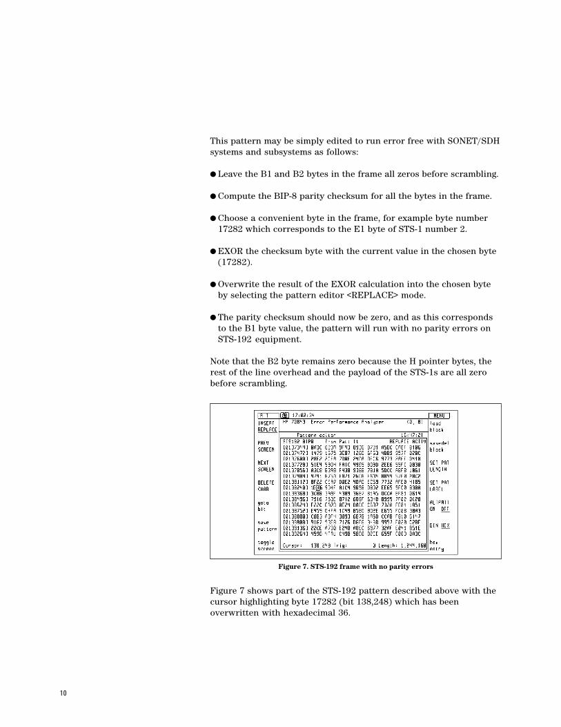
Figure 7 shows part of the STS-192 pattern described above with thecursor highlighting byte 17282 (bit 138,248) which has beenoverwritten with hexadecimal 36.
Figure 7. STS-192 frame with no parity errors

11
Testing 10 Gb/s SONET/SDHequipment and components
Pseudo-dynamic testing withalternating patterns
The 71612C analyzer can switch error free (hitlessly or synchro-nously) between two different user-programmable long patterns;these may be up to 4 Mbits long, but must be of identical length.Pattern selection is under the control of a front panel key,HP-IB or the auxiliary input port; changeover is synchronous withthe end of a word. The length of the alternating patterns should be amultiple of 256 bits. The instrument will output one of two patterns(A or B) at the end of either pattern. The auxiliary input controlswhich pattern is output in one of two modes:
l Oneshot – a rising edge on the auxiliary input inserts a singleversion of pattern B into repetitions of pattern A.
l Alternate – the logic state of the signal at the auxiliary input deter-mines which pattern is output. A logic 0 will output pattern A.
Note: The error detector is not affected by the pattern switching andis set to pattern A when alternate pattern is selected. In alternatepattern mode, a pattern trigger pulse output is provided; this occursat bit 0 of the selected pattern.
The alternate pattern feature offers great potential for pseudo-dynamic testing of framing algorithms, failure states and alarms.
SONET/SDH systems test withuser-programmable patterns
The framed pattern with no parity errors is suitable for jitter toler-ance testing (with a suitable clock source) when the built-in parityerror alarm of the LTE/STE is used to flag the onset of errors. Thepattern has many additional uses as a basic framed STS-192 pattern.Real-time editing of this pattern may be used to confirm the opera-tion of equipment parity error alarms.
The alternate pattern mode of pattern generation facilitates theconstruction of patterns that test failure states and algorithms.
Jitter testing with framed zero parity error pattern
Failure states and maintenance signals
parity errors
loss of signal (LOS)
framing algorithm (LOF)(OOF)
alarm indicator signals (AIS)
loss of pointer (LOP)
Block BER measurement
overhead bytes BER
payload BER

12
Loss of signal (LOS) alarm may be tested by increasing the run ofzeros in one pattern until the LOS state is entered; this shouldcorrespond to 100 ms or more of zeros (> 1,045,095 bits at STS-192).The LOS state should be exited after two valid frames are received.The LOS algorithm may be examined by alternating between a validpattern and the pattern containing the run of zeros.
In SONET systems the out of frame (OOF) state is entered when fourconsecutive frames are received with errored framing patterns, andexited after two valid frames are received. The equipment loss offrame (LOF) signal is required to be activated by an STS-192 signalthat is in the OOF state for 24 frames or more. The LOF alarm shouldtherefore be activated after 28 or more consecutive frames have beenreceived with errored framing patterns, and the equipment shouldframe-up after two valid frames are received. The operation of thealarms may be tested by using alternating patterns containingerrored and valid framing bytes.
A single pattern to stress test the frame alignment system may alsobe constructed consisting of five STS-192 frames; two valid framesfollowed by three errored frames. The equipment should not enter anout-of-frame state when receiving this pattern.
The loss of pointer (LOP) failure state may be tested by switchingbetween a framed pattern containing valid pointer bytes and onecontaining non-valid pointer bytes.
In SONET systems, major alarm conditions such as LOS, LOP, LOFcause the alarm indication signal (AIS) to be transmitteddownstream. This signal may be simulated with a pattern consistingof valid section overhead bytes and a scrambled all ones pattern inthe rest of the frame. This may be simply constructed on a PC, savedon a floppy disk and downloaded into the 71612C analyzer.
The failure state algorithms may be fully tested by selecting thepatterns generated in alternate pattern mode by means of anexternal controller connected to the generator auxiliary input. Thecontroller also counts the pulses received from the pattern generatortrigger output. In this way it is possible to control the number ofrepetitions of each of the alternate patterns, and hence to select thenumber of frames transmitted. For example, this would allow theLOF failure mode to be fully tested with a sequence of 28 or moreerrored frames followed by the required number (8 to 24) ofrepetitions of valid framing patterns.

13
In the past, bit error ratio test sets performed quantitative BERmeasurements that simply informed the user that his device undertest had a certain error ratio. The results gave no indication of thepossible cause of the errors. The next step was the introduction ofsimple diagnostics such as errored and error free intervalmeasurement. In recent years the facility to independently measurethe BER of errored ones and zeros has been added. This suite offeatures provided the user with some indication of the cause oferrors.
The 71612C analyzer now introduces the next generation of errordiagnostics, error location analysis (ELA). ELA helps the user toidentify systematic errors.
Error location analysis functions only with RAM-based patterns.These include user-programmable patterns, and the PRBS-basedpatterns such as variable mark density and zero substitution that aregenerated from RAM in the 71612C analyzer.
Error location analysis consists of a suite of three measurements:
l Bit BER allows a user to specify any bit in a pattern and toperform BER measurements on that bit alone.
l Block BER allows BER measurements to be performed on aselected range of bits within a user-defined pattern. The range ofbits must be a multiple of 32 with the block specified by a startlocation and block length. This feature is essential when trying tolocate the cause of systematic errors which can affect a section ofbits in a pattern – for example pattern-dependent errors in thesection overhead bytes of an STS-192 frame.
l Error location capture allows the user to capture the actualposition of errored bits in a user-defined pattern. After initiationof the measurement, the error detector locates the first (or next)errored bit in the pattern, displays the errored bit, and thesequence of bits either side of the errored bit. The error detectorautomatically measures the BER of the errored bit. If this BERremains significant over a period of time, it indicates the presenceof a systematic or pattern-dependent error. This feature helps theuser to differentiate between random and systematic errors, thushelping to identify the source of errors.
Error location analysis

14
Figure 8 shows a block BER measurement being performed on thefirst 4608 bits of a 1,244,160 bits STS-192 pattern (block start ad-dress = 0, block length = 4608) The block error ratio is 7.056e-5. Theblock selected from the STS-192 pattern consists of the A1, A2 andC1 bytes from the section overhead.
Figure 9 shows the capture of bit 3,322 from a pattern of 1,244,160bits. The 28 bits preceding the errored bit are displayed in the datawindow. The bit BER is 8.348e-7.
The pattern trigger output on the 71612C analyzer may be used totrigger an oscilloscope to automatically display the errored bits andadjacent parts of the pattern as they are captured.
Figure 8. Example of STS-192 block BER measurement
Figure 9. Example of error capture and bit BER
15
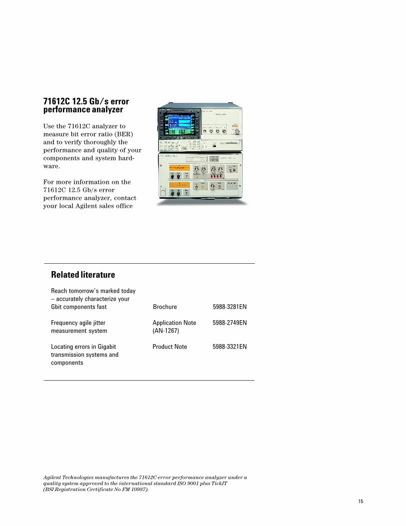
71612C 12.5 Gb/s errorperformance analyzer
Use the 71612C analyzer tomeasure bit error ratio (BER)and to verify thoroughly theperformance and quality of yourcomponents and system hard-ware.
For more information on the71612C 12.5 Gb/s errorperformance analyzer, contactyour local Agilent sales office
Related literature
Reach tomorrow’s marked today– accurately characterize yourGbit components fast Brochure 5988-3281EN
Frequency agile jitter Application Note 5988-2749ENmeasurement system (AN-1267)
Locating errors in Gigabit Product Note 5988-3321ENtransmission systems andcomponents
Agilent Technologies manufactures the 71612C error performance analyzer under aquality system approved to the international standard ISO 9001 plus TickIT(BSI Registration Certificate No FM 10987).

Agilent Technologies’Test and Measurement Support,Services, and Assistance
Agilent Technologies aims to maximize thevalue you receive, while minimizing your riskand problems. We strive to ensure that youget the test and measurement capabilitiesyou paid for and obtain the support you need.Our extensive support resources and servicescan help you choose the right Agilentproducts for your applications and applythem successfully. Every instrument andsystem we sell has a global warranty. Supportis available for at least five years beyond theproduction life of the product. Two conceptsunderlie Agilent’s overall support policy:“Our Promise” and “Your Advantage.”
Our PromiseOur Promise means your Agilent test andmeasurement equipment will meet itsadvertised performance and functionality.When you are choosing new equipment, wewill help you with product information,including realistic performance specificationsand practical recommendations fromexperienced test engineers. When you useAgilent equipment, we can verify that itworks properly, help with product operation,and provide basic measurement assistancefor the use of specified capabilities, at noextra cost upon request. Many self-help toolsare available.
Your AdvantageYour Advantage means that Agilent offers awide range of additional expert test andmeasurement services, which you canpurchase according to your unique technicaland business needs. Solve problemsefficiently and gain a competitive edge bycontracting with us for calibration, extra-costupgrades, out-of-warranty repairs, and on-siteeducation and training, as well as design,system integration, project management, andother professional engineering services.Experienced Agilent engineers andtechnicians worldwide can help youmaximize your productivity, optimize thereturn on investment of your Agilentinstruments and systems, and obtaindependable measurement accuracy for thelife of those products.
By internet, phone, or fax, get assistance with allyour test & measurement needs
Online assistance:www.agilent.com/find/assist
Phone or FaxUnited States:(tel) 1 800 452 4844
Canada:(tel) 1 877 894 4414(fax) (905) 206 4120
Europe:(tel) (31 20) 547 2323(fax) (31 20) 547 2390
Japan:(tel) (81) 426 56 7832(fax) (81) 426 56 7840
Latin America:(tel) (305) 267 4245(fax) (305) 267 4286
Australia:(tel) 1 800 629 485(fax) (61 3) 9272 0749
New Zealand:(tel) 0 800 738 378(fax) 64 4 495 8950
Asia Pacific:(tel) (852) 3197 7777(fax) (852) 2506 9284
Product specifications and descriptionsin this document subject to changewithout notice.
© Agilent Technologies, 2001Printed in UK18 July, 20015988-3322EN