configuring channelized sonet/sdh - cisco€¦ · configuring channelized sonet/sdh on the cisco...
TRANSCRIPT
Configuring Channelized SONET/SDH on the Cisco ASR 9000 Series Router
This module describes the configuration of Channelized SONET/SDH on the Cisco ASR 9000 Series Aggregation Services Routers.
Feature History for Configuring Channelized SONET/SDH on Cisco IOS XR Software
Contents• Prerequisites for Configuring Channelized SONET/SDH, page 1
• Information About Configuring Channelized SONET/SDH, page 2
• How to Configure Channelized SONET/SDH, page 11
• Configuration Examples for Channelized SONET, page 38
Prerequisites for Configuring Channelized SONET/SDHYou must be in a user group associated with a task group that includes the proper task IDs. The command reference guides include the task IDs required for each command. If you suspect user group assignment is preventing you from using a command, contact your AAA administrator for assistance.
Release Modification
Release 3.9.0 Support for the following SPA was introduced on the Cisco ASR 9000 Series Router:
• Cisco 2-Port Channelized OC-12/DS0 SPA
Release 4.0.0 Support for the following SPA was introduced on the Cisco ASR 9000 Series Router:
• Cisco 1-Port Channelized OC-48/STM-16 SPA
Support for SDH, E3, E1, and POS channelization was added for the Cisco 2-Port Channelized OC-12/DS0 and Cisco 1-Port Channelized OC-48/STM-16 SPAs.
Release 4.0.1 Support for the following SPA was introduced on the Cisco ASR 9000 Series Router:
• Cisco 1-Port Channelized OC-3/STM-1 SPA
11Cisco ASR 9000 Aggregation Services Router Interface and Hardware Component Configuration Guide
OL-28377-02
Configuring Channelized SONET/SDH on the Cisco ASR 9000 Series RouterInformation About Configuring Channelized SONET/SDH
Before configuring Channelized SONET/SDH, be sure that the following tasks and conditions are met:
• You have at least one of the following SPAs installed in your chassis:
– Cisco 1-Port Channelized OC-3/STM-1 SPA
– Cisco 2-Port Channelized OC-12c/DS0 SPA
– Cisco 1-Port Channelized OC-48/STM-16 SPA
• You should know how to apply and specify the SONET controller name and interface-path-id with the generalized notation rack/slot/module/port. The SONET controller name and interface-path-id are required with the controller sonet command.
Information About Configuring Channelized SONET/SDHTo configure Channelized SONET/SDH, you must understand the following concepts:
• Channelized SONET Overview, page 2
• Channelized SDH Overview, page 7
• Default Configuration Values for Channelized SONET/SDH, page 10
• How to Configure Channelized SONET/SDH, page 11
Channelized SONET OverviewSynchronous Optical Network (SONET) is an American National Standards Institute (ANSI) specification format used in transporting digital telecommunications services over optical fiber.
Synchronous Digital Hierarchy (SDH) is the international equivalent of SONET.
Channelized SONET provides the ability to transport SONET frames across multiplexed T3/E3 and virtual tributary group (VTG) channels.
Channelized SONET is supported on the following SPAs:
• Cisco 1-Port Channelized OC-48/STM-16 SPA
• Cisco 1-Port Channelized OC-3/STM-1 SPA
• Cisco 2-Port Channelized OC-12c/DS0 SPA
Channelized SDH is supported on the following SPAs:
• Cisco 1-Port Channelized OC-48/STM-16 SPA
• Cisco 1-Port Channelized OC-3/STM-1 SPA
• Cisco 2-Port Channelized OC-12c/DS0 SPA
SONET uses Synchronous Transport Signal (STS) framing. An STS is the electrical equivalent to an optical carrier 1 (OC-1).
SDH uses Synchronous Transport Mode (STM) framing. An STM-1 is the electrical equivalent to 3 optical carrier 1s (OC-1s).
A channelized SONET interface is a composite of STS streams, which are maintained as independent frames with unique payload pointers. The frames are multiplexed before transmission.
12Cisco ASR 9000 Aggregation Services Router Interface and Hardware Component Configuration Guide
OL-28377-02

Configuring Channelized SONET/SDH on the Cisco ASR 9000 Series RouterInformation About Configuring Channelized SONET/SDH
When a line is channelized, it is logically divided into smaller bandwidth channels called paths. These paths carry the SONET payload. The sum of the bandwidth on all paths cannot exceed the line bandwidth.
When a line is not channelized, it is called clear channel, and the full bandwidth of the line is dedicated to a single channel that carries broadband services.
An STS stream can be channelized into the following types of channels:
• T3/E3
• VT1.5 mapped T1
• Packet over SONET/SDH (POS) (OC12 and OC48 only)
The T3/E3 channels can be channelized further into T1s, and the T1s can be channelized into time slots (DS0s), except on the 1-Port Channelized OC-48/STM-16 SPA, which does not support T1 or DS0s.
Channelizing a SONET line consists of two primary processes:
• Configuring the controller
• Configuring the interface into channelized paths
You configure the controller first by setting the mode of the STS path. The mode can be set to T3, or VT1.5-mapped T1, or POS, depending on your hardware support.
Note POS is supported only on the STS-3c and STS-12c paths on the Cisco 1-Port Channelized OC-12/DS0 SPA and on the STS-3c, STS-12c, and STS-48c paths on the Cisco 1-Port Channelized OC-48/STM-16 SPA.
When the mode is specified, the respective controller is created, and the remainder of the configuration is applied on that controller. For example, mode T3 creates a T3 controller. The T3 controller can then be configured to a serial channel, or it can be further channelized to carry T1s, and those T1s can be configured to serial interfaces.
Depending on the support for your installed SPA, each STS path can be independently configured into T3s, E3s, or VTGs, and so on.
13Cisco ASR 9000 Aggregation Services Router Interface and Hardware Component Configuration Guide
OL-28377-02
Configuring Channelized SONET/SDH on the Cisco ASR 9000 Series RouterInformation About Configuring Channelized SONET/SDH
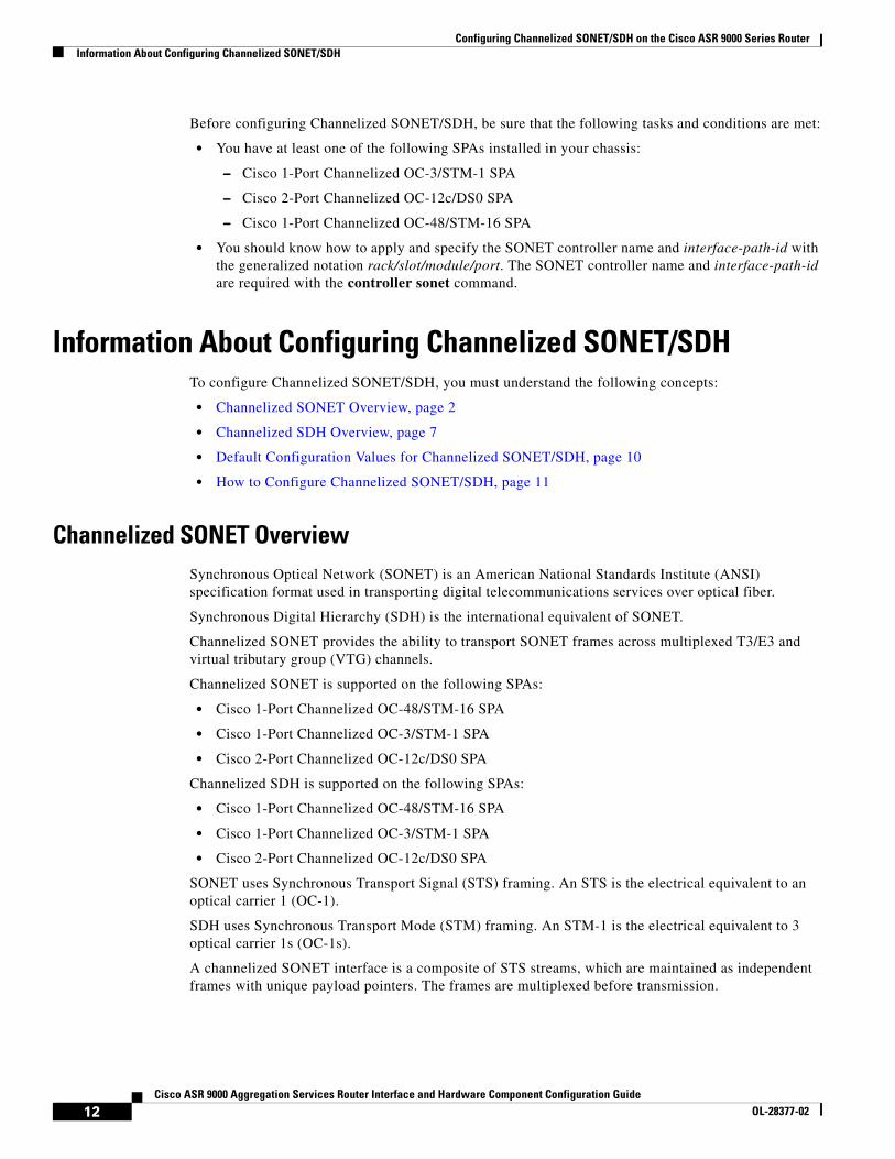
Figure 1 shows an example of three STS paths for a SONET controller. However, the 2-Port Channelized OC-12/DS0 SPA supports up to 12 STS paths, and the 1-Port Channelized OC-48/STM-16 SPA supports up to 48 STS paths, but the 1-Port Channelized OC-48/STM-16 SPA does not support VTGs.
Figure 1 SONET Controller STS Paths
STS 3
SONETController
. . . can be configured as T3s or VTGs
STS 2 . . . can be configured as T3s or VTGs
STS 1 . . . can be configured as T3s or VTGs
2108
70
14Cisco ASR 9000 Aggregation Services Router Interface and Hardware Component Configuration Guide
OL-28377-02
Configuring Channelized SONET/SDH on the Cisco ASR 9000 Series RouterInformation About Configuring Channelized SONET/SDH
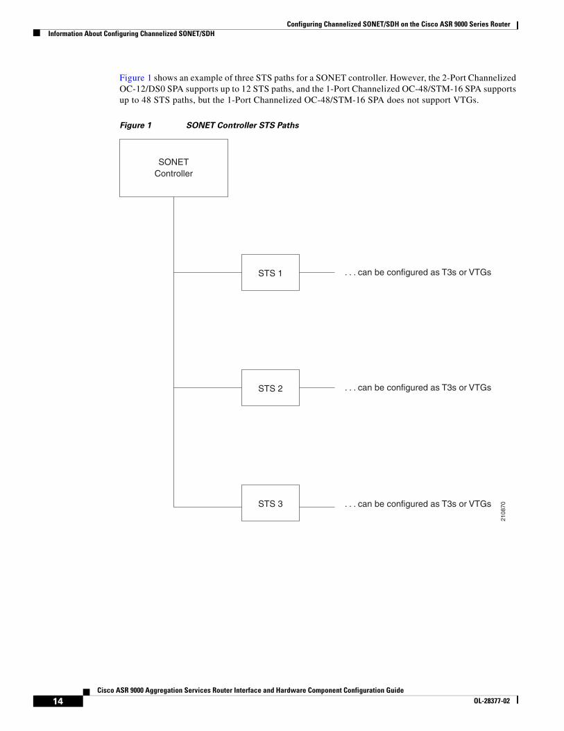
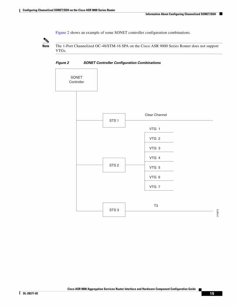
Figure 2 shows an example of some SONET controller configuration combinations.
Note The 1-Port Channelized OC-48/STM-16 SPA on the Cisco ASR 9000 Series Router does not support VTGs.
Figure 2 SONET Controller Configuration Combinations
STS 3
SONETController
STS 2
STS 1
Clear Channel
T3
2108
73
VTG 1
VTG 2
VTG 3
VTG 4
VTG 5
VTG 6
VTG 7
15Cisco ASR 9000 Aggregation Services Router Interface and Hardware Component Configuration Guide
OL-28377-02
Configuring Channelized SONET/SDH on the Cisco ASR 9000 Series RouterInformation About Configuring Channelized SONET/SDH
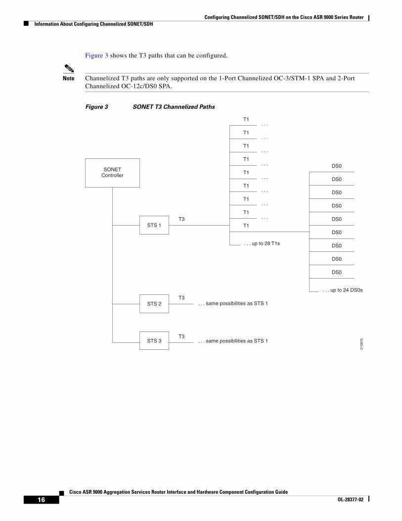
Figure 3 shows the T3 paths that can be configured.
Note Channelized T3 paths are only supported on the 1-Port Channelized OC-3/STM-1 SPA and 2-Port Channelized OC-12c/DS0 SPA.
Figure 3 SONET T3 Channelized Paths
STS 3
SONETController
. . . same possibilities as STS 1
STS 2 . . . same possibilities as STS 1
STS 1
2108
76
DS0
DS0
DS0
DS0
DS0
DS0
DS0
DS0
DS0
. . . up to 24 DS0s
T1
T1
T1
T1
T1
T1
T1
T1
T1T3
T3
T3
. . . up to 28 T1s
. . .
. . .
. . .
. . .
. . .
. . .
. . .
. . .
16Cisco ASR 9000 Aggregation Services Router Interface and Hardware Component Configuration Guide
OL-28377-02
Configuring Channelized SONET/SDH on the Cisco ASR 9000 Series RouterInformation About Configuring Channelized SONET/SDH
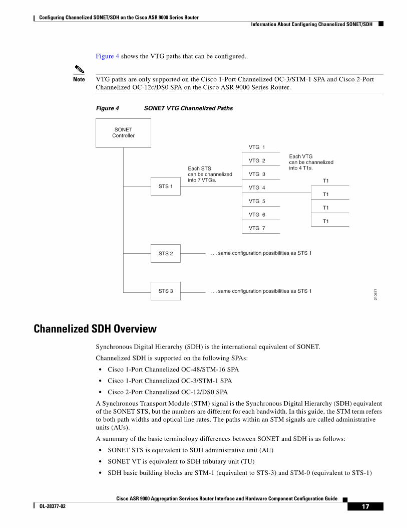
Figure 4 shows the VTG paths that can be configured.
Note VTG paths are only supported on the Cisco 1-Port Channelized OC-3/STM-1 SPA and Cisco 2-Port Channelized OC-12c/DS0 SPA on the Cisco ASR 9000 Series Router.
Figure 4 SONET VTG Channelized Paths
Channelized SDH Overview Synchronous Digital Hierarchy (SDH) is the international equivalent of SONET.
Channelized SDH is supported on the following SPAs:
• Cisco 1-Port Channelized OC-48/STM-16 SPA
• Cisco 1-Port Channelized OC-3/STM-1 SPA
• Cisco 2-Port Channelized OC-12/DS0 SPA
A Synchronous Transport Module (STM) signal is the Synchronous Digital Hierarchy (SDH) equivalent of the SONET STS, but the numbers are different for each bandwidth. In this guide, the STM term refers to both path widths and optical line rates. The paths within an STM signals are called administrative units (AUs).
A summary of the basic terminology differences between SONET and SDH is as follows:
• SONET STS is equivalent to SDH administrative unit (AU)
• SONET VT is equivalent to SDH tributary unit (TU)
• SDH basic building blocks are STM-1 (equivalent to STS-3) and STM-0 (equivalent to STS-1)
STS 3
SONETController
. . . same configuration possibilities as STS 1
STS 2 . . . same configuration possibilities as STS 1
STS 1
2108
77
VTG 1
VTG 2
VTG 3
VTG 4
VTG 5
VTG 6
VTG 7
T1
T1
T1
T1
Each STS can be channelizedinto 7 VTGs.
Each VTG can be channelized into 4 T1s.
17Cisco ASR 9000 Aggregation Services Router Interface and Hardware Component Configuration Guide
OL-28377-02
Configuring Channelized SONET/SDH on the Cisco ASR 9000 Series RouterInformation About Configuring Channelized SONET/SDH
An administrative unit (AU) is the information structure that provides adaptation between the higher-order path layer and the multiplex section layer. It consists of an information payload (the higher-order virtual container) and an administrative unit pointer, which indicates the offset of the payload frame start relative to the multiplex section frame start.
An AU can be channelized into tributary units (TUs) and tributary unit groups (TUGs).
An administrative unit 4 (AU-4) consists of three STM-1s or an STM-3.
An administrative unit 3 (AU-3) consists of one STM-1.
An administrative unit group (AUG) consists of one or more administrative units occupying fixed, defined positions in an STM payload.
On the Cisco ASR 9000 Series Router, the following levels of SDH channelization are supported:
• 1-Port Channelized OC-3/STM-1 SPA
– AU4 to TUG-3 to TUG-2 to VC-12 to E1 to NxDS0
– AU4 to TUG-3 to VC-3 to DS3 (Clear Channel)
– AU4 to TUG-3 to VC-3 to E3 (Clear Channel)
– AU3 to TUG-2 to VC-11 to DS1 to NxDS0
• 2-Port Channelized OC-12/DS0 SPA
– AU-4-4c (VC-4-4c)
– AU-4 (VC-4)
– AU-4 to TUG-3 to VC-3 to DS3
– AU-4 to TUG-3 to VC-3 to E3
– AU-4 to TUG-3 to TUG-2 to VC-11 to T1 to NxDS0
– AU-4 to TUG-3 to TUG-2 to VC-12 to E1to NxDS0
– AU-3 to VC-3 to DS3
– AU-3 to TUG-2 to VC-11 to T1 to NxDS0
– AU-3 to TUG-2 to VC-12 to E1to NxDS0
– AU-3 to VC-3 to E3
– AU-3 to VC-3 to DS3 to T1 to NxDS0
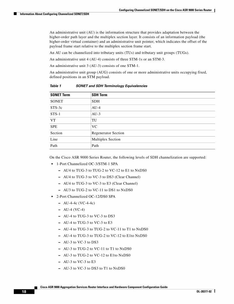
Table 1 SONET and SDH Terminology Equivalencies
SONET Term SDH Term
SONET SDH
STS-3c AU-4
STS-1 AU-3
VT TU
SPE VC
Section Regenerator Section
Line Multiplex Section
Path Path
18Cisco ASR 9000 Aggregation Services Router Interface and Hardware Component Configuration Guide
OL-28377-02

Configuring Channelized SONET/SDH on the Cisco ASR 9000 Series RouterInformation About Configuring Channelized SONET/SDH
– AU-3 to VC-3 to DS3 to E1 to NxDS0
• 1-Port Channelized OC-48/STM-16 SPA
– DS3
– E3
– AU-3 (VC-3)
– AU-4 (VC-4)
– AU-4-4c (VC-4-4c)
– AU-4-16c (VC-4-16c)
Figure 5 shows an example of SDH AU-3 paths that can be configured on certain supported SPAs.
Note The 1-Port Channelized OC-48/STM-16 SPA does not support further channelization of AU-3 paths into T1s.
Figure 5 SDH AU3 Paths
SONETController
2108
74
C11-T1
T1
AU-3
C11-T1
T1
AU-3
C11-T1
T1
AU-3
STM-1
19Cisco ASR 9000 Aggregation Services Router Interface and Hardware Component Configuration Guide
OL-28377-02

Configuring Channelized SONET/SDH on the Cisco ASR 9000 Series RouterInformation About Configuring Channelized SONET/SDH
Figure 6 shows the SDH AU4 paths that can be configured on supported SPAs.
Note The 1-Port Channelized OC-48/STM-16 SPA only supports channelization to the T3 or E3 level. Further channelization of AU-4 paths is not supported.
Figure 6 SDH AU4 Paths
Default Configuration Values for Channelized SONET/SDHTable 2 describes the default configuration parameters that are present on the Channelized SONET/SDH.
SONETController
2108
75
TUG-3
T3
or C12
AU-4STM-1
E1
E1
E1
E1
E1
E1
E1
E1
E1
E1
Up to 21 E1s
Table 2 SONET/SDH Controller Default Cit onfiguration Values
Parameter Default Value Configuration File Entry
Clock source line clock source {internal | line}
SONET framing sonet framing {sdh | sonet}
110Cisco ASR 9000 Aggregation Services Router Interface and Hardware Component Configuration Guide
OL-28377-02
Configuring Channelized SONET/SDH on the Cisco ASR 9000 Series RouterHow to Configure Channelized SONET/SDH
How to Configure Channelized SONET/SDHThis section contains the following procedures:
• Configuring SONET T3 and VT1.5-Mapped T1 Channels, page 11
• Configuring Packet over SONET Channels, page 16
• Configuring a Clear Channel SONET Controller for T3, page 19
• Configuring Channelized SONET APS, page 22
• Configuring SDH AU-3, page 25
• Configuring SDH AU-4, page 33
Configuring SONET T3 and VT1.5-Mapped T1 Channels This task explains how to configure a SONET line into T3 and VT-mapped T1 Channels.
Prerequisites
• You should know how to configure the SONET controller as specified in the “How to Configure Clear Channel SONET Controllers” section of the Configuring Clear Channel SONET Controllers on the Cisco ASR 9000 Series Router module.
• STS paths can be channelized into T3s on the following SPAs:
– Cisco 1-Port Channelized OC-48/STM-16 SPA
– Cisco 1-Port Channelized OC-3/STM-1 SPA
– Cisco 2-Port Channelized OC-12/DS0 SPA
• STS paths can be channelized into VTG mapped T1s on the following SPA:
– Cisco 1-Port Channelized OC-3/STM-1 SPA
– Cisco 2-Port Channelized OC-12/DS0 SPA
• T3 paths can be channelized into T1s or E1s on the following SPA:
– Cisco 1-Port Channelized OC-3/STM-1 SPA
– Cisco 2-Port Channelized OC-12/DS0 SPA
• T1 paths can be channelized into NxDS0s on the Cisco 2-Port Channelized OC-12/DS0 SPA.
Restrictions
T1s and E1s are not supported on the Cisco 1-Port Channelized OC-48/STM-16 SPA.
SUMMARY STEPS
1. configure
2. controller sonet interface-path-id
3. clock source {internal | line}
4. framing sonet
111Cisco ASR 9000 Aggregation Services Router Interface and Hardware Component Configuration Guide
OL-28377-02

Configuring Channelized SONET/SDH on the Cisco ASR 9000 Series RouterHow to Configure Channelized SONET/SDH
5. sts number
6. mode mode
7. width number
8. root
9. controller controllerName instance
10. mode mode
11. root
12. controller t1 interface-path-id
13. channel-group number
14. timeslots num1:num2:num3:num4 ortimeslots range1-range2
15. show configuration
16. root
17. interface serial interface-path-id
18. encapsulation {frame-relay | hdlc | ppp}
19. ipv4 ip-address mask
20. no shutdown
21. endorcommit
22. show
DETAILED STEPS
Command or Action Purpose
Step 1 configure
Example:RP/0/RSP0/CPU0:router# configure
Enters global configuration mode.
Step 2 controller sonet interface-path-id
Example:RP/0/RSP0/CPU0:router(config)# controller sonet 0/1/1/0
Enters SONET controller configuration submode and specifies the SONET controller name and interface-path-id with the rack/slot/module/port notation.
112Cisco ASR 9000 Aggregation Services Router Interface and Hardware Component Configuration Guide
OL-28377-02

Configuring Channelized SONET/SDH on the Cisco ASR 9000 Series RouterHow to Configure Channelized SONET/SDH
Step 3 clock source {internal | line}
Example:RP/0/RSP0/CPU0:router(config-sonet)# clock source internal
Configures the SONET port transmit clock source, where the internal keyword sets the internal clock and the line keyword sets the clock recovered from the line.
• Use the line keyword whenever clocking is derived from the network. Use the internal keyword when two routers are connected back to back or over fiber for which no clocking is available.
• line is the default keyword.
Note Internal clocking is required for SRP interfaces.
Step 4 framing sonet
Example:RP/0/RSP0/CPU0:router(config-sonet)# framing sonet
Configures the controller for SONET framing.
SONET framing (sonet) is the default.
Step 5 sts number
Example:RP/0/RSP0/CPU0:router(config-sonet)# sts 1
Configures the STS stream specified by number. The ranges are:
• 1 to 48—1 Port Channelized OC-48/STM-16 SPA
• 1 to 3—1-Port Channelized OC-3/STM-1 SPA
• 1 to 12—2-Port Channelized OC-12/DS0 SPA
Step 6 mode mode
Example:RP/0/RSP0/CPU0:router(config-stsPath)# mode t3
Sets the mode of interface at the STS level. The possible modes are:
• t3—SONET path carrying T3
• vt15-t1—SONET path carrying virtual tributary 1.5 T1s (VT15 T1) (1-Port Channelized OC-3/STM-1 SPA and 2-Port Channelized OC-12c/DS0 SPA only)
• pos—Packet over SONET
Step 7 width number
Example:RP/0/RSP0/CPU0:router(config-stsPath)# width 3
Configures the number of the STS streams that are concatenated. The possible values for number are:
• 1—Indicating one STS stream
• 3—Indicating three STS streams (STS-3c)
• 12—Indicating concatenation of 12 STS streams (STS-12c)
• 48—Indicating concatenation of 48 STS streams (STS-48c). This is the default on the 1-Port Channelized OC-48/STM-16 SPA.
Widths 3, and 12, and 48 are configured on STS paths at natural boundaries, which coincide with the following path numbers:
• 1, 4, 7, 10, and so on, for STS-3c
• 1, 13, 25, and 37 for STS-12c
• 1 for STS-48c
Step 8 root
Example:RP/0/RSP0/CPU0:router(config-stsPath)# root
Exits to global configuration mode.
Command or Action Purpose
113Cisco ASR 9000 Aggregation Services Router Interface and Hardware Component Configuration Guide
OL-28377-02
Configuring Channelized SONET/SDH on the Cisco ASR 9000 Series RouterHow to Configure Channelized SONET/SDH
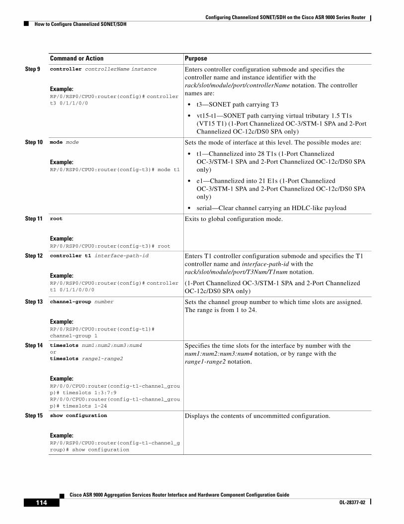
Step 9 controller controllerName instance
Example:RP/0/RSP0/CPU0:router(config)# controller t3 0/1/1/0/0
Enters controller configuration submode and specifies the controller name and instance identifier with the rack/slot/module/port/controllerName notation. The controller names are:
• t3—SONET path carrying T3
• vt15-t1—SONET path carrying virtual tributary 1.5 T1s (VT15 T1) (1-Port Channelized OC-3/STM-1 SPA and 2-Port Channelized OC-12c/DS0 SPA only)
Step 10 mode mode
Example:RP/0/RSP0/CPU0:router(config-t3)# mode t1
Sets the mode of interface at this level. The possible modes are:
• t1—Channelized into 28 T1s (1-Port Channelized OC-3/STM-1 SPA and 2-Port Channelized OC-12c/DS0 SPA only)
• e1—Channelized into 21 E1s (1-Port Channelized OC-3/STM-1 SPA and 2-Port Channelized OC-12c/DS0 SPA only)
• serial—Clear channel carrying an HDLC-like payload
Step 11 root
Example:RP/0/RSP0/CPU0:router(config-t3)# root
Exits to global configuration mode.
Step 12 controller t1 interface-path-id
Example:RP/0/RSP0/CPU0:router(config)# controller t1 0/1/1/0/0/0
Enters T1 controller configuration submode and specifies the T1 controller name and interface-path-id with the rack/slot/module/port/T3Num/T1num notation.
(1-Port Channelized OC-3/STM-1 SPA and 2-Port Channelized OC-12c/DS0 SPA only)
Step 13 channel-group number
Example:RP/0/RSP0/CPU0:router(config-t1)# channel-group 1
Sets the channel group number to which time slots are assigned. The range is from 1 to 24.
Step 14 timeslots num1:num2:num3:num4 ortimeslots range1-range2
Example:RP/0/0/CPU0:router(config-t1-channel_group)# timeslots 1:3:7:9RP/0/0/CPU0:router(config-t1-channel_group)# timeslots 1-24
Specifies the time slots for the interface by number with the num1:num2:num3:num4 notation, or by range with the range1-range2 notation.
Step 15 show configuration
Example:RP/0/RSP0/CPU0:router(config-t1-channel_group)# show configuration
Displays the contents of uncommitted configuration.
Command or Action Purpose
114Cisco ASR 9000 Aggregation Services Router Interface and Hardware Component Configuration Guide
OL-28377-02

Configuring Channelized SONET/SDH on the Cisco ASR 9000 Series RouterHow to Configure Channelized SONET/SDH
Step 16 root
Example:RP/0/RSP0/CPU0:router(config-t3)# root
Exits to global configuration mode.
Step 17 interface serial interface-path-id
Example:RP/0/RSP0/CPU0:router(config)# interface serial 0/1/1/0/0/0:0
Specifies the complete interface number with the rack/slot/module/port/T3Num/T1num:instance notation.
Step 18 encapsulation {frame-relay | hdlc | ppp}
Example:RP/0/RSP0/CPU0:router(config-if)# encapsulation ppp
Specifies the encapsulation type with the one of the following keywords:
• frame-relay—Frame Relay network protocol
• hdlc—High-level Data Link Control (HDLC) synchronous protocol
• ppp—Point-to-Point Protocol
Step 19 ipv4 ip-address mask
Example:RP/0/RSP0/CPU0:router(config-if)# ip address 10.10.10.10 255.255.255.255
Assigns an IP address and subnet mask to the interface.
Step 20 no shutdown
Example:RP/0/RSP0/CPU0:router(config-if)# no shutdown
Removes the shutdown configuration.
Note Removal of the shutdown configuration eliminates the forced administrative down on the interface, enabling it to move to an up or down state (assuming that the parent SONET layer is not configured administratively down).
Command or Action Purpose
115Cisco ASR 9000 Aggregation Services Router Interface and Hardware Component Configuration Guide
OL-28377-02
Configuring Channelized SONET/SDH on the Cisco ASR 9000 Series RouterHow to Configure Channelized SONET/SDH
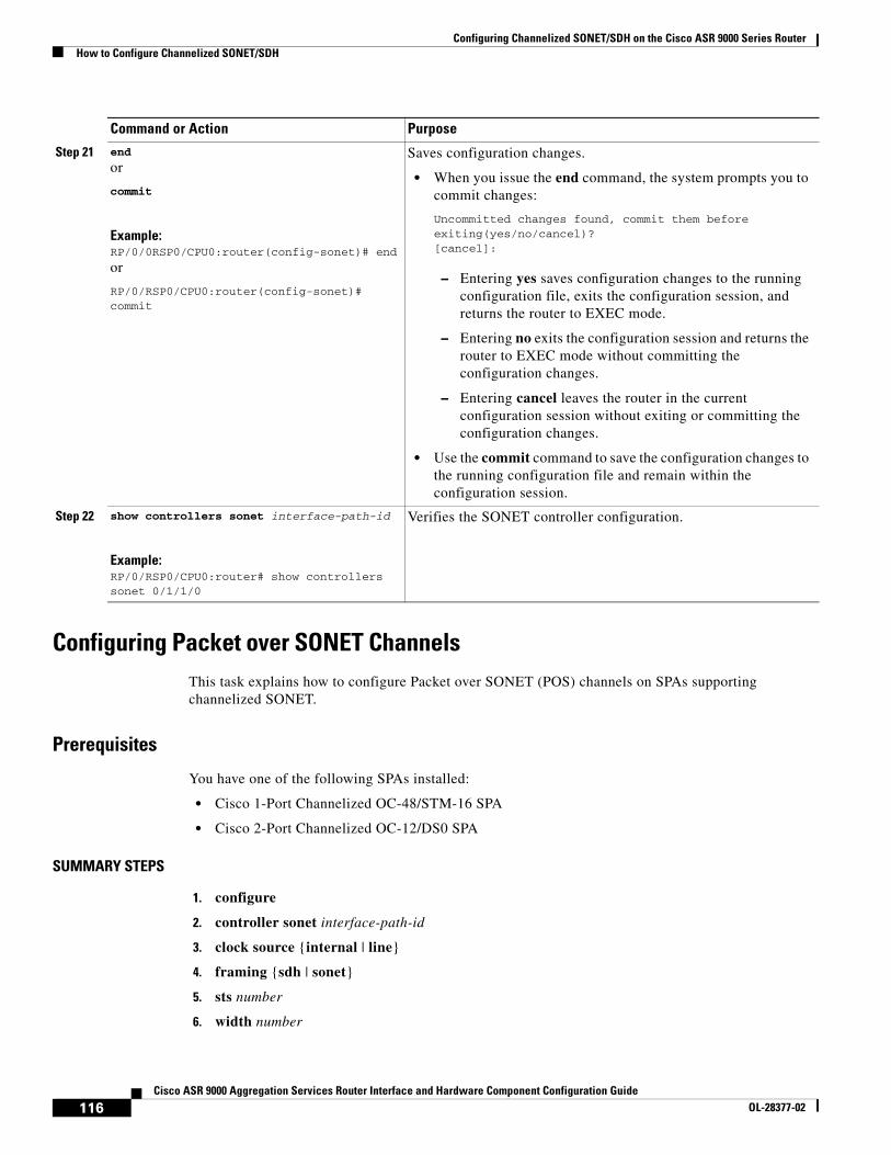
Configuring Packet over SONET Channels This task explains how to configure Packet over SONET (POS) channels on SPAs supporting channelized SONET.
Prerequisites
You have one of the following SPAs installed:
• Cisco 1-Port Channelized OC-48/STM-16 SPA
• Cisco 2-Port Channelized OC-12/DS0 SPA
SUMMARY STEPS
1. configure
2. controller sonet interface-path-id
3. clock source {internal | line}
4. framing {sdh | sonet}
5. sts number
6. width number
Step 21 end
or
commit
Example:RP/0/0RSP0/CPU0:router(config-sonet)# end
or
RP/0/RSP0/CPU0:router(config-sonet)# commit
Saves configuration changes.
• When you issue the end command, the system prompts you to commit changes:
Uncommitted changes found, commit them before exiting(yes/no/cancel)? [cancel]:
– Entering yes saves configuration changes to the running configuration file, exits the configuration session, and returns the router to EXEC mode.
– Entering no exits the configuration session and returns the router to EXEC mode without committing the configuration changes.
– Entering cancel leaves the router in the current configuration session without exiting or committing the configuration changes.
• Use the commit command to save the configuration changes to the running configuration file and remain within the configuration session.
Step 22 show controllers sonet interface-path-id
Example:RP/0/RSP0/CPU0:router# show controllers sonet 0/1/1/0
Verifies the SONET controller configuration.
Command or Action Purpose
116Cisco ASR 9000 Aggregation Services Router Interface and Hardware Component Configuration Guide
OL-28377-02
Configuring Channelized SONET/SDH on the Cisco ASR 9000 Series RouterHow to Configure Channelized SONET/SDH
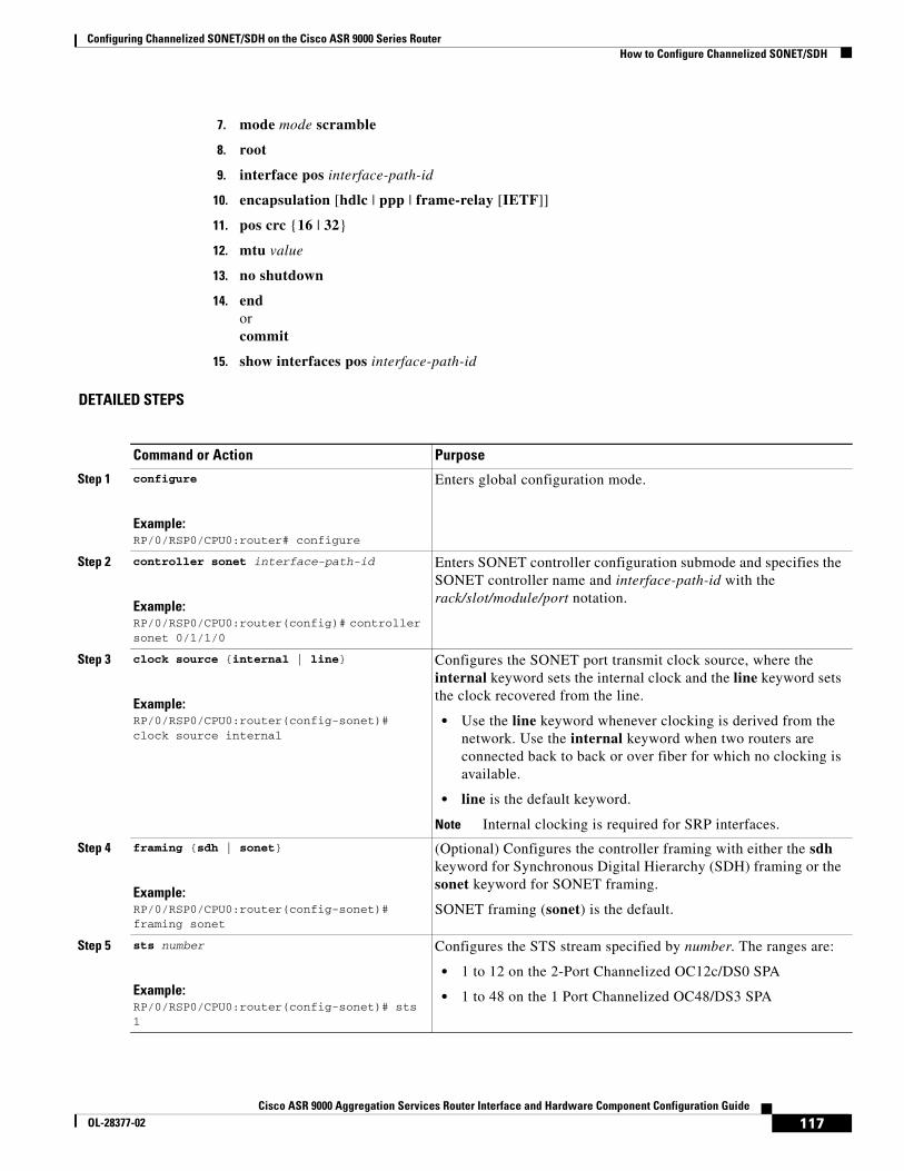
7. mode mode scramble
8. root
9. interface pos interface-path-id
10. encapsulation [hdlc | ppp | frame-relay [IETF]]
11. pos crc {16 | 32}
12. mtu value
13. no shutdown
14. end orcommit
15. show interfaces pos interface-path-id
DETAILED STEPS
Command or Action Purpose
Step 1 configure
Example:RP/0/RSP0/CPU0:router# configure
Enters global configuration mode.
Step 2 controller sonet interface-path-id
Example:RP/0/RSP0/CPU0:router(config)# controller sonet 0/1/1/0
Enters SONET controller configuration submode and specifies the SONET controller name and interface-path-id with the rack/slot/module/port notation.
Step 3 clock source {internal | line}
Example:RP/0/RSP0/CPU0:router(config-sonet)# clock source internal
Configures the SONET port transmit clock source, where the internal keyword sets the internal clock and the line keyword sets the clock recovered from the line.
• Use the line keyword whenever clocking is derived from the network. Use the internal keyword when two routers are connected back to back or over fiber for which no clocking is available.
• line is the default keyword.
Note Internal clocking is required for SRP interfaces.
Step 4 framing {sdh | sonet}
Example:RP/0/RSP0/CPU0:router(config-sonet)# framing sonet
(Optional) Configures the controller framing with either the sdh keyword for Synchronous Digital Hierarchy (SDH) framing or the sonet keyword for SONET framing.
SONET framing (sonet) is the default.
Step 5 sts number
Example:RP/0/RSP0/CPU0:router(config-sonet)# sts 1
Configures the STS stream specified by number. The ranges are:
• 1 to 12 on the 2-Port Channelized OC12c/DS0 SPA
• 1 to 48 on the 1 Port Channelized OC48/DS3 SPA
117Cisco ASR 9000 Aggregation Services Router Interface and Hardware Component Configuration Guide
OL-28377-02

Configuring Channelized SONET/SDH on the Cisco ASR 9000 Series RouterHow to Configure Channelized SONET/SDH
Step 6 width number
Example:RP/0/RSP0/CPU0:router(config-stsPath)# width 3
Configures the number of the STS streams that are concatenated. The possible values for number are:
• 3—Indicating three STS streams (STS-3c)
• 12—Indicating concatenation of 12 STS streams (STS-12c)
• 48—Indicating concatenation of 48 STS streams (STS-48c)
Widths 3, 12, and 48 are configured on STS paths at natural boundaries, which coincide with the following path numbers:
• 1, 4, 7, 10, and so on, for STS-3c
• 1, 13, 25, and 37 for STS-12c
• 1 for STS-48c
Note POS interfaces are not supported when width is 1.
Step 7 mode mode scramble
Example:RP/0/RSP0/CPU0:router(config-stsPath)# mode pos scramble
Sets the mode of interface at the STS level. Set the mode to pos to create POS interface (OC12 and OC48 only).
Step 8 root
Example:RP/0/RSP0/CPU0:router(config-stsPath)# root
Exits to global configuration mode.
Step 9 interface pos interface-path-id
Example:RP/0/RSP0/CPU0:router(config)# interface POS 0/1/1/0
Specifies the POS interface name and notation rack/slot/module/port, and enters interface configuration mode.
Step 10 encapsulation [hdlc | ppp | frame-relay [IETF]]
Example:RP/0/RSP0/CPU0:router(config-if)# encapsulation hdlc
(Optional) Configures the interface encapsulation parameters and details such as HDLC or PPP. The default is HDLC.
Step 11 pos crc {16 | 32}
Example:RP/0/RSP0/CPU0:router(config-if)# pos crc 32
(Optional) Configures the CRC value for the interface. Enter the 16 keyword to specify 16-bit CRC mode, or enter the 32 keyword to specify 32-bit CRC mode.
The default CRC is 32.
Step 12 mtu value
Example:RP/0/RSP0/CPU0:router(config-if)# mtu 4474
(Optional) Configures the POS MTU value.
The range is 64–65535.
Command or Action Purpose
118Cisco ASR 9000 Aggregation Services Router Interface and Hardware Component Configuration Guide
OL-28377-02

Configuring Channelized SONET/SDH on the Cisco ASR 9000 Series RouterHow to Configure Channelized SONET/SDH
Configuring a Clear Channel SONET Controller for T3This task explains how to configure a SONET line into a single T3 serial channel called clear channel. Clear channel is established by setting the T3 controller mode to serial.
Prerequisites
• You should know how to configure the SONET controller as specified in the “How to Configure Clear Channel SONET Controllers” section of the Configuring Clear Channel SONET Controllers on the Cisco ASR 9000 Series Router module.
SUMMARY STEPS
1. configure
2. controller sonet interface-path-id
3. clock source {internal | line}
Step 13 no shutdown
Example:RP/0/RSP0/CPU0:router (config-if)# no shutdown
Removes the shutdown configuration.
Note Removal of the shutdown configuration eliminates the forced administrative down on the interface, enabling it to move to an up or down state (assuming that the parent SONET layer is not configured administratively down).
Step 14 end
or
commit
Example:RP/0/RSP0/CPU0:router(config-sonet)# end
or
RP/0/RSP0/CPU0:router(config-sonet)# commit
Saves configuration changes.
• When you issue the end command, the system prompts you to commit changes:
Uncommitted changes found, commit them before exiting(yes/no/cancel)? [cancel]:
– Entering yes saves configuration changes to the running configuration file, exits the configuration session, and returns the router to EXEC mode.
– Entering no exits the configuration session and returns the router to EXEC mode without committing the configuration changes.
– Entering cancel leaves the router in the current configuration session without exiting or committing the configuration changes.
• Use the commit command to save the configuration changes to the running configuration file and remain within the configuration session.
Step 15 show interfaces pos interface-path-id
Example:RP/0/0/CPU0:router# show interfaces pos 0/1/1/0
(Optional) Displays the interface configuration.
Command or Action Purpose
119Cisco ASR 9000 Aggregation Services Router Interface and Hardware Component Configuration Guide
OL-28377-02
Configuring Channelized SONET/SDH on the Cisco ASR 9000 Series RouterHow to Configure Channelized SONET/SDH
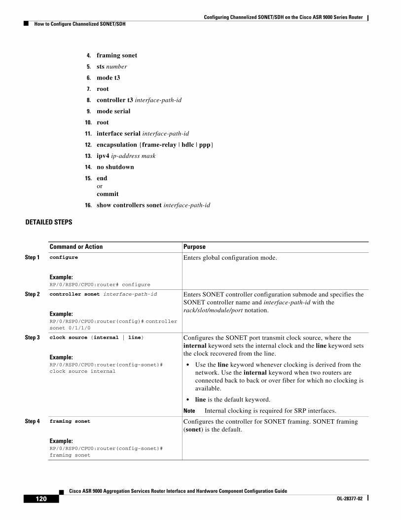
4. framing sonet
5. sts number
6. mode t3
7. root
8. controller t3 interface-path-id
9. mode serial
10. root
11. interface serial interface-path-id
12. encapsulation {frame-relay | hdlc | ppp}
13. ipv4 ip-address mask
14. no shutdown
15. end or commit
16. show controllers sonet interface-path-id
DETAILED STEPS
Command or Action Purpose
Step 1 configure
Example:RP/0/RSP0/CPU0:router# configure
Enters global configuration mode.
Step 2 controller sonet interface-path-id
Example:RP/0/RSP0/CPU0:router(config)# controller sonet 0/1/1/0
Enters SONET controller configuration submode and specifies the SONET controller name and interface-path-id with the rack/slot/module/port notation.
Step 3 clock source {internal | line}
Example:RP/0/RSP0/CPU0:router(config-sonet)# clock source internal
Configures the SONET port transmit clock source, where the internal keyword sets the internal clock and the line keyword sets the clock recovered from the line.
• Use the line keyword whenever clocking is derived from the network. Use the internal keyword when two routers are connected back to back or over fiber for which no clocking is available.
• line is the default keyword.
Note Internal clocking is required for SRP interfaces.
Step 4 framing sonet
Example:RP/0/RSP0/CPU0:router(config-sonet)# framing sonet
Configures the controller for SONET framing. SONET framing (sonet) is the default.
120Cisco ASR 9000 Aggregation Services Router Interface and Hardware Component Configuration Guide
OL-28377-02
Configuring Channelized SONET/SDH on the Cisco ASR 9000 Series RouterHow to Configure Channelized SONET/SDH
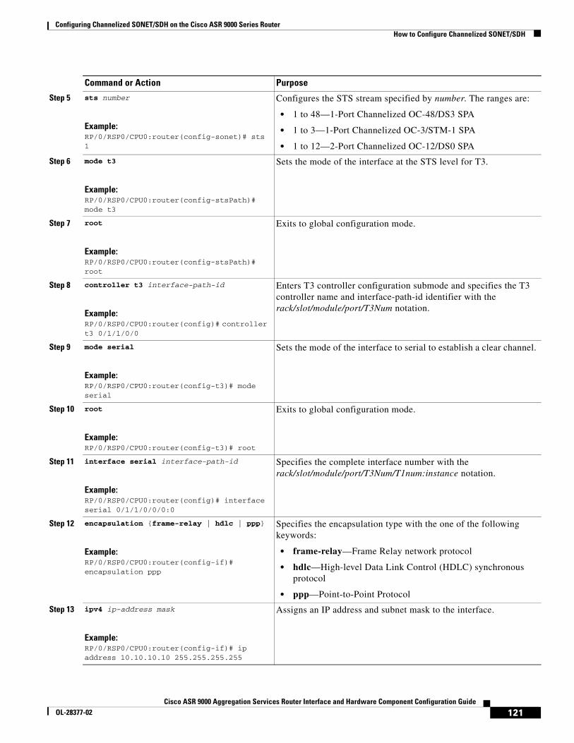
Step 5 sts number
Example:RP/0/RSP0/CPU0:router(config-sonet)# sts 1
Configures the STS stream specified by number. The ranges are:
• 1 to 48—1-Port Channelized OC-48/DS3 SPA
• 1 to 3—1-Port Channelized OC-3/STM-1 SPA
• 1 to 12—2-Port Channelized OC-12/DS0 SPA
Step 6 mode t3
Example:RP/0/RSP0/CPU0:router(config-stsPath)# mode t3
Sets the mode of the interface at the STS level for T3.
Step 7 root
Example:RP/0/RSP0/CPU0:router(config-stsPath)# root
Exits to global configuration mode.
Step 8 controller t3 interface-path-id
Example:RP/0/RSP0/CPU0:router(config)# controller t3 0/1/1/0/0
Enters T3 controller configuration submode and specifies the T3 controller name and interface-path-id identifier with the rack/slot/module/port/T3Num notation.
Step 9 mode serial
Example:RP/0/RSP0/CPU0:router(config-t3)# mode serial
Sets the mode of the interface to serial to establish a clear channel.
Step 10 root
Example:RP/0/RSP0/CPU0:router(config-t3)# root
Exits to global configuration mode.
Step 11 interface serial interface-path-id
Example:RP/0/RSP0/CPU0:router(config)# interface serial 0/1/1/0/0/0:0
Specifies the complete interface number with the rack/slot/module/port/T3Num/T1num:instance notation.
Step 12 encapsulation {frame-relay | hdlc | ppp}
Example:RP/0/RSP0/CPU0:router(config-if)# encapsulation ppp
Specifies the encapsulation type with the one of the following keywords:
• frame-relay—Frame Relay network protocol
• hdlc—High-level Data Link Control (HDLC) synchronous protocol
• ppp—Point-to-Point Protocol
Step 13 ipv4 ip-address mask
Example:RP/0/RSP0/CPU0:router(config-if)# ip address 10.10.10.10 255.255.255.255
Assigns an IP address and subnet mask to the interface.
Command or Action Purpose
121Cisco ASR 9000 Aggregation Services Router Interface and Hardware Component Configuration Guide
OL-28377-02

Configuring Channelized SONET/SDH on the Cisco ASR 9000 Series RouterHow to Configure Channelized SONET/SDH
Configuring Channelized SONET APS This task explains how to configure APS for channelized SONET lines.
Prerequisites
• You should know how to configure the SONET controller as specified in the “How to Configure Clear Channel SONET Controllers” section of the Configuring Clear Channel SONET Controllers on the Cisco ASR 9000 Series Router module.
• You should know how to configure the SONET APS as specified in the “Configuring SONET APS” section of the Configuring Clear Channel SONET Controllers on the Cisco ASR 9000 Series Router module.
Step 14 no shutdown
Example:RP/0/RSP0/CPU0:router(config-if)# no shutdown
Removes the shutdown configuration.
Note Removal of the shutdown configuration eliminates the forced administrative down on the interface, enabling it to move to an up or down state (assuming that the parent SONET layer is not configured administratively down).
Step 15 end
or
commit
Example:RP/0/RSP0/CPU0:router(config-sonet)# end
or
RP/0/RSP0/CPU0:router(config-sonet)# commit
Saves configuration changes.
• When you issue the end command, the system prompts you to commit changes:
Uncommitted changes found, commit them before exiting(yes/no/cancel)? [cancel]:
– Entering yes saves configuration changes to the running configuration file, exits the configuration session, and returns the router to EXEC mode.
– Entering no exits the configuration session and returns the router to EXEC mode without committing the configuration changes.
– Entering cancel leaves the router in the current configuration session without exiting or committing the configuration changes.
• Use the commit command to save the configuration changes to the running configuration file and remain within the configuration session.
Step 16 show controllers sonet interface-path-id
Example:RP/0//RSP0/CPU0:router# show controllers sonet 0/1/1/0
Verifies the SONET controller configuration.
Command or Action Purpose
122Cisco ASR 9000 Aggregation Services Router Interface and Hardware Component Configuration Guide
OL-28377-02
Configuring Channelized SONET/SDH on the Cisco ASR 9000 Series RouterHow to Configure Channelized SONET/SDH
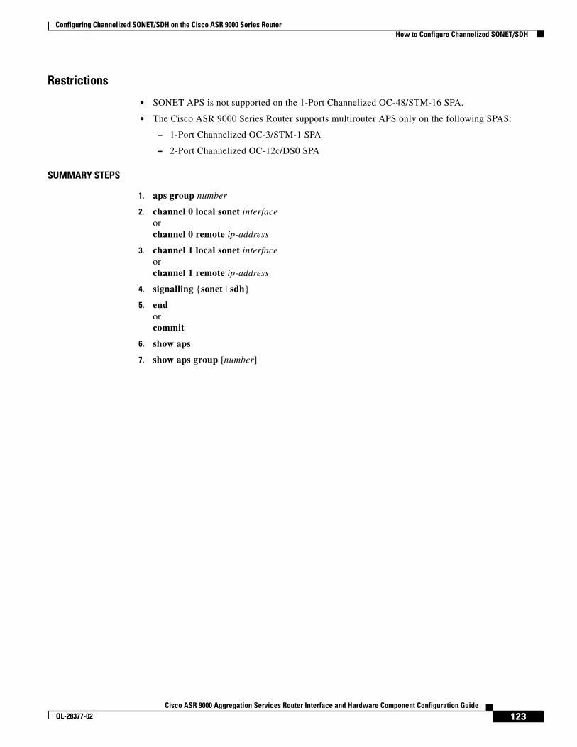
Restrictions
• SONET APS is not supported on the 1-Port Channelized OC-48/STM-16 SPA.
• The Cisco ASR 9000 Series Router supports multirouter APS only on the following SPAS:
– 1-Port Channelized OC-3/STM-1 SPA
– 2-Port Channelized OC-12c/DS0 SPA
SUMMARY STEPS
1. aps group number
2. channel 0 local sonet interfaceorchannel 0 remote ip-address
3. channel 1 local sonet interfaceorchannel 1 remote ip-address
4. signalling {sonet | sdh}
5. end orcommit
6. show aps
7. show aps group [number]
123Cisco ASR 9000 Aggregation Services Router Interface and Hardware Component Configuration Guide
OL-28377-02

Configuring Channelized SONET/SDH on the Cisco ASR 9000 Series RouterHow to Configure Channelized SONET/SDH
DETAILED STEPS
Command or Action Purpose
Step 1 aps group number
Example:RP/0/RSP0/CPU0:router(config)# aps group 1
Adds an APS group with a specified number and enters APS group configuration mode.
• Use the aps group command in global configuration mode.
• To remove a group, use the no form of this command, as in: no aps group number, where the value range is from 1 to 255.
Note To use the aps group command, you must be a member of a user group associated with the proper task IDs for APS commands.
Note The aps group command is used even when a single protect group is configured.
Step 2 channel 0 local sonet interfaceorchannel 0 remote ip-address
Example:RP/0/RSP0/CPU0:router(config-aps)# channel 0 local SONET 0/0/0/1or RP/0/RSP0/CPU0:router(config-aps)# channel 0 remote 172.18.69.123
Creates a protect channel for the APS group, where 0 designates a protect channel.
Note The protect channel must be assigned before the active channel can be assigned.
Note To configure APS where both channels are on one router, use the channel local command for both the protect and active channels.To configure APS using two different routers where the active channel is on one router and the protect channel is on another router, use the channel local command for either the protect or the active channel, but use the channel remote command for the other channel.
Step 3 channel 1 local sonet interfaceorchannel 1 remote ip-address
Example:RP/0/RSP0/CPU0:router(config-aps)# channel 1 local SONET 0/0/0/2or RP/0/0/CPU0:router(config-aps)# channel 1 remote 172.18.69.123
Creates an active channel for the APS group, where 1 designates an active channel.
Note The active channel must be assigned after the protect channel is assigned.
Note To configure APS where both channels are on one router, use the channel local command for both the protect and active channels.To configure APS using two different routers where the active channel is on one router and the protect channel is on another router, use the channel local command for either the protect or the active channel, but use the channel remote command for the other channel.
Step 4 signalling {sonet | sdh}
Example:RP/0/RSP0/CPU0:router(config-aps)# signalling sonet
Configures the K1K2 overhead byte used for automatic protection switching (APS). The keyword options are:
• sonet—Sets signaling to SONET.
• sdh—Sets signaling to Synchronous Digital Hierarchy (SDH).
124Cisco ASR 9000 Aggregation Services Router Interface and Hardware Component Configuration Guide
OL-28377-02

Configuring Channelized SONET/SDH on the Cisco ASR 9000 Series RouterHow to Configure Channelized SONET/SDH
Configuring SDH AU-3This section includes the following tasks:
• Configuring SDH AU-3 Mapped to C11-T1 or C12-E1, page 25
• Configuring SDH AU-3 Mapped to T3 or E3, page 29
Configuring SDH AU-3 Mapped to C11-T1 or C12-E1
This task explains how to configure SDH AU-3 with c11-t1 or c12-e1 mapping.
Prerequisites
• You should know how to configure the SONET controller as specified in the “How to Configure Clear Channel SONET Controllers” section of the Configuring Clear Channel SONET Controllers on the Cisco ASR 9000 Series Router module.
Step 5 end
or
commit
Example:RP/0/RSP0/CPU0:router(config-sonet)# end
or
RP/0/RSP0/CPU0:router(config-sonet)# commit
Saves configuration changes.
• When you issue the end command, the system prompts you to commit changes:
Uncommitted changes found, commit them before exiting(yes/no/cancel)? [cancel]:
– Entering yes saves configuration changes to the running configuration file, exits the configuration session, and returns the router to EXEC mode.
– Entering no exits the configuration session and returns the router to EXEC mode without committing the configuration changes.
– Entering cancel leaves the router in the current configuration session without exiting or committing the configuration changes.
• Use the commit command to save the configuration changes to the running configuration file and remain within the configuration session.
Step 6 show aps
Example:RP/0/RSP0/CPU0:router# show aps
(Optional) Displays the operational status for all configured SONET APS groups.
Step 7 show aps group [number]
Example:RP/0/RSP0/CPU0:router# show aps group 3
(Optional) Displays the operational status for configured SONET APS groups.
Note The show aps group command is more useful than the show aps command when multiple groups are defined.
Command or Action Purpose
125Cisco ASR 9000 Aggregation Services Router Interface and Hardware Component Configuration Guide
OL-28377-02
Configuring Channelized SONET/SDH on the Cisco ASR 9000 Series RouterHow to Configure Channelized SONET/SDH
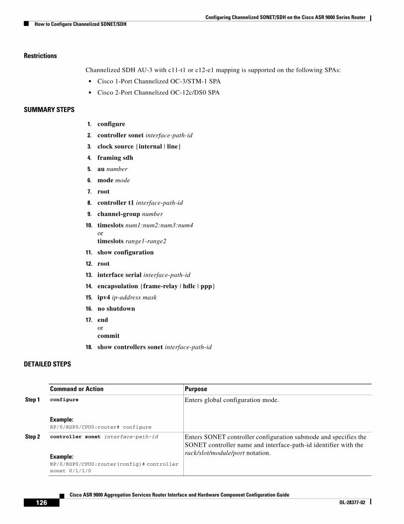
Restrictions
Channelized SDH AU-3 with c11-t1 or c12-e1 mapping is supported on the following SPAs:
• Cisco 1-Port Channelized OC-3/STM-1 SPA
• Cisco 2-Port Channelized OC-12c/DS0 SPA
SUMMARY STEPS
1. configure
2. controller sonet interface-path-id
3. clock source {internal | line}
4. framing sdh
5. au number
6. mode mode
7. root
8. controller t1 interface-path-id
9. channel-group number
10. timeslots num1:num2:num3:num4 ortimeslots range1-range2
11. show configuration
12. root
13. interface serial interface-path-id
14. encapsulation {frame-relay | hdlc | ppp}
15. ipv4 ip-address mask
16. no shutdown
17. end orcommit
18. show controllers sonet interface-path-id
DETAILED STEPS
Command or Action Purpose
Step 1 configure
Example:RP/0/RSP0/CPU0:router# configure
Enters global configuration mode.
Step 2 controller sonet interface-path-id
Example:RP/0/RSP0/CPU0:router(config)# controller sonet 0/1/1/0
Enters SONET controller configuration submode and specifies the SONET controller name and interface-path-id identifier with the rack/slot/module/port notation.
126Cisco ASR 9000 Aggregation Services Router Interface and Hardware Component Configuration Guide
OL-28377-02

Configuring Channelized SONET/SDH on the Cisco ASR 9000 Series RouterHow to Configure Channelized SONET/SDH
Step 3 clock source {internal | line}
Example:RP/0/RSP0/CPU0:router(config-sonet)# clock source internal
Configures the SONET port transmit clock source, where the internal keyword sets the internal clock and the line keyword sets the clock recovered from the line.
• Use the line keyword whenever clocking is derived from the network. Use the internal keyword when two routers are connected back to back or over fiber for which no clocking is available.
• line is the default keyword.
Note Internal clocking is required for SRP interfaces.
Step 4 framing sdh
Example:RP/0/RSP0/CPU0:router(config-sonet)# framing sdh
Configures the controller framing for Synchronous Digital Hierarchy (SDH) framing.
SONET framing (sonet) is the default.
Step 5 au number
Example:RP/0/RSP0/CPU0:router(config-sonet)# au 1
Specifies the administrative unit (AU) group and enters AU path configuration mode. For AU-3, the valid range is:
• 1 to 3—1-Port Channelized OC-3/STM-1 SPA
• 1 to 12—2-Port Channelized OC-12c/DS0 SPA
Note The au command does not specify the AU type. It specifies the number of the AU group for the AU type that you want to configure. The range for the AU command varies based on whether you are configuring AU-3 or AU-4.
Step 6 mode mode
Example:RP/0/RSP0/CPU0:router(config-auPath)# mode c11-t1
Sets the mode of interface at the AU level. AU-3 paths can be mapped to c11-t1 or c12-e1 on supported SPAs.
Step 7 root
Example:RP/0/RSP0/CPU0:router(config-auPath)# root
Exits to global configuration mode.
Step 8 controller t1 interface-path-id
Example:RP/0/RSP0/CPU0:router(config)# controller T1 0/1/1/0/0/0/0
Enters T1 controller configuration submode and specifies the T1 controller name and interface-path-id with the rack/slot/module/port/auNum/t1Num notation.
Step 9 channel-group number
Example:RP/0/RSP0/CPU0:router(config-t1)# channel-group 0
Sets the channel-group number to which time slots are assigned. The range is from 1 to 28.
Command or Action Purpose
127Cisco ASR 9000 Aggregation Services Router Interface and Hardware Component Configuration Guide
OL-28377-02
Configuring Channelized SONET/SDH on the Cisco ASR 9000 Series RouterHow to Configure Channelized SONET/SDH
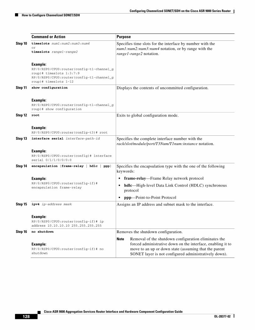
Step 10 timeslots num1:num2:num3:num4 ortimeslots range1-range2
Example:RP/0/RSP0/CPU0:router(config-t1-channel_group)# timeslots 1:3:7:9RP/0/RSP0/CPU0:router(config-t1-channel_group)# timeslots 1-12
Specifies time slots for the interface by number with the num1:num2:num3:num4 notation, or by range with the range1-range2 notation.
Step 11 show configuration
Example:RP/0/RSP0/CPU0:router(config-t1-channel_group)# show configuration
Displays the contents of uncommitted configuration.
Step 12 root
Example:RP/0/RSP0/CPU0:router(config-t3)# root
Exits to global configuration mode.
Step 13 interface serial interface-path-id
Example:RP/0/RSP0/CPU0:router(config)# interface serial 0/1/1/0/0/0:0
Specifies the complete interface number with the rack/slot/module/port/T3Num/T1num:instance notation.
Step 14 encapsulation {frame-relay | hdlc | ppp}
Example:RP/0/RSP0/CPU0:router(config-if)# encapsulation frame-relay
Specifies the encapsulation type with the one of the following keywords:
• frame-relay—Frame Relay network protocol
• hdlc—High-level Data Link Control (HDLC) synchronous protocol
• ppp—Point-to-Point Protocol
Step 15 ipv4 ip-address mask
Example:RP/0/RSP0/CPU0:router(config-if)# ip address 10.10.10.10 255.255.255.255
Assigns an IP address and subnet mask to the interface.
Step 16 no shutdown
Example:RP/0/RSP0/CPU0:router(config-if)# no shutdown
Removes the shutdown configuration.
Note Removal of the shutdown configuration eliminates the forced administrative down on the interface, enabling it to move to an up or down state (assuming that the parent SONET layer is not configured administratively down).
Command or Action Purpose
128Cisco ASR 9000 Aggregation Services Router Interface and Hardware Component Configuration Guide
OL-28377-02
Configuring Channelized SONET/SDH on the Cisco ASR 9000 Series RouterHow to Configure Channelized SONET/SDH
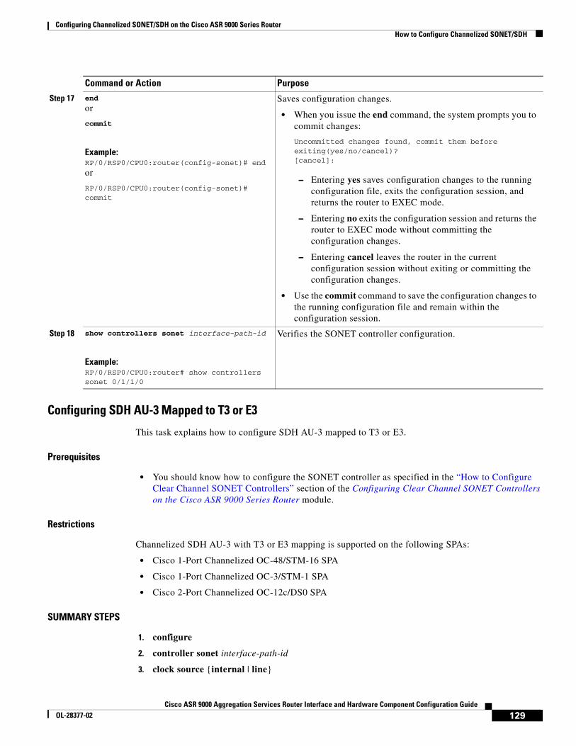
Configuring SDH AU-3 Mapped to T3 or E3
This task explains how to configure SDH AU-3 mapped to T3 or E3.
Prerequisites
• You should know how to configure the SONET controller as specified in the “How to Configure Clear Channel SONET Controllers” section of the Configuring Clear Channel SONET Controllers on the Cisco ASR 9000 Series Router module.
Restrictions
Channelized SDH AU-3 with T3 or E3 mapping is supported on the following SPAs:
• Cisco 1-Port Channelized OC-48/STM-16 SPA
• Cisco 1-Port Channelized OC-3/STM-1 SPA
• Cisco 2-Port Channelized OC-12c/DS0 SPA
SUMMARY STEPS
1. configure
2. controller sonet interface-path-id
3. clock source {internal | line}
Step 17 end
or
commit
Example:RP/0/RSP0/CPU0:router(config-sonet)# end
or
RP/0/RSP0/CPU0:router(config-sonet)# commit
Saves configuration changes.
• When you issue the end command, the system prompts you to commit changes:
Uncommitted changes found, commit them before exiting(yes/no/cancel)? [cancel]:
– Entering yes saves configuration changes to the running configuration file, exits the configuration session, and returns the router to EXEC mode.
– Entering no exits the configuration session and returns the router to EXEC mode without committing the configuration changes.
– Entering cancel leaves the router in the current configuration session without exiting or committing the configuration changes.
• Use the commit command to save the configuration changes to the running configuration file and remain within the configuration session.
Step 18 show controllers sonet interface-path-id
Example:RP/0/RSP0/CPU0:router# show controllers sonet 0/1/1/0
Verifies the SONET controller configuration.
Command or Action Purpose
129Cisco ASR 9000 Aggregation Services Router Interface and Hardware Component Configuration Guide
OL-28377-02
Configuring Channelized SONET/SDH on the Cisco ASR 9000 Series RouterHow to Configure Channelized SONET/SDH
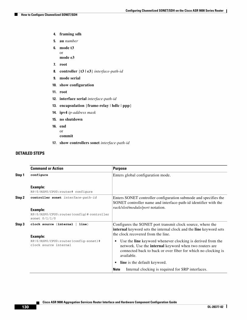
4. framing sdh
5. au number
6. mode t3ormode e3
7. root
8. controller {t3 | e3} interface-path-id
9. mode serial
10. show configuration
11. root
12. interface serial interface-path-id
13. encapsulation {frame-relay | hdlc | ppp}
14. ipv4 ip-address mask
15. no shutdown
16. end orcommit
17. show controllers sonet interface-path-id
DETAILED STEPS
Command or Action Purpose
Step 1 configure
Example:RP/0/RSP0/CPU0:router# configure
Enters global configuration mode.
Step 2 controller sonet interface-path-id
Example:RP/0/RSP0/CPU0:router(config)# controller sonet 0/1/1/0
Enters SONET controller configuration submode and specifies the SONET controller name and interface-path-id identifier with the rack/slot/module/port notation.
Step 3 clock source {internal | line}
Example:RP/0/RSP0/CPU0:router(config-sonet)# clock source internal
Configures the SONET port transmit clock source, where the internal keyword sets the internal clock and the line keyword sets the clock recovered from the line.
• Use the line keyword whenever clocking is derived from the network. Use the internal keyword when two routers are connected back to back or over fiber for which no clocking is available.
• line is the default keyword.
Note Internal clocking is required for SRP interfaces.
130Cisco ASR 9000 Aggregation Services Router Interface and Hardware Component Configuration Guide
OL-28377-02

Configuring Channelized SONET/SDH on the Cisco ASR 9000 Series RouterHow to Configure Channelized SONET/SDH
Step 4 framing sdh
Example:RP/0/RSP0/CPU0:router(config-sonet)# framing sdh
Configures the controller framing for Synchronous Digital Hierarchy (SDH) framing.
SONET framing (sonet) is the default.
Step 5 au number
Example:RP/0/RSP0/CPU0:router(config-sonet)# au 1
Specifies the administrative unit (AU) group and enters AU path configuration mode. For AU-3, the valid range is:
• 1 to 48—1-Port Channelized OC-48/DS3 SPA
• 1 to 3—1-Port Channelized OC-3/STM-1 SPA
• 1 to 12—2-Port Channelized OC-12c/DS0 SPA
Note The au command does not specify the AU type. It specifies the number of the AU group for the AU type that you want to configure. The range for the AU command varies based on whether you are configuring AU-3 or AU-4.
Step 6 mode t3or mode e3
Example:RP/0/RSP0/CPU0:router(config-auPath)# mode t3
Sets the mode of interface at the AU level to T3 or E3.
Step 7 root
Example:RP/0/RSP0/CPU0:router(config-auPath)# root
Exits to global configuration mode.
Step 8 controller {t3 | e3} interface-path-id
Example:RP/0/RSP0/CPU0:router(config)# controller T3 0/1/1/0/0
Enters T3 or E3 controller configuration submode and specifies the T3 or E3 controller name and interface-path-id with the rack/slot/module/port/auNum notation.
Step 9 mode serial
Example:RP/0/RSP0/CPU0:router(config-t3)# mode serial
Configures the mode of the port to be clear channel serial.
Step 10 show configuration
Example:RP/0/RSP0/CPU0:router(config-t3)# show configuration
Displays the contents of uncommitted configuration.
Step 11 root
Example:RP/0/RSP0/CPU0:router(config-t3)# root
Exits to global configuration mode.
Command or Action Purpose
131Cisco ASR 9000 Aggregation Services Router Interface and Hardware Component Configuration Guide
OL-28377-02
Configuring Channelized SONET/SDH on the Cisco ASR 9000 Series RouterHow to Configure Channelized SONET/SDH
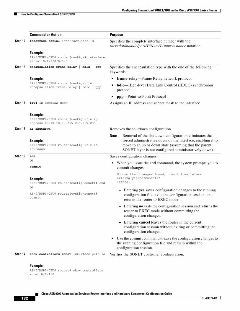
Step 12 interface serial interface-path-id
Example:RP/0/RSP0/CPU0:router(config)# interface serial 0/1/1/0/0/0:0
Specifies the complete interface number with the rack/slot/module/port/T3Num/T1num:instance notation.
Step 13 encapsulation frame-relay | hdlc | ppp
Example:RP/0/RSP0/CPU0:router(config-if)# encapsulation frame-relay | hdlc | ppp
Specifies the encapsulation type with the one of the following keywords:
• frame-relay—Frame Relay network protocol
• hdlc—High-level Data Link Control (HDLC) synchronous protocol
• ppp—Point-to-Point Protocol
Step 14 ipv4 ip-address mask
Example:RP/0/RSP0/CPU0:router(config-if)# ip address 10.10.10.10 255.255.255.255
Assigns an IP address and subnet mask to the interface.
Step 15 no shutdown
Example:RP/0/RSP0/CPU0:router(config-if)# no shutdown
Removes the shutdown configuration.
Note Removal of the shutdown configuration eliminates the forced administrative down on the interface, enabling it to move to an up or down state (assuming that the parent SONET layer is not configured administratively down).
Step 16 end
or
commit
Example:RP/0/RSP0/CPU0:router(config-sonet)# end
or
RP/0/RSP0/CPU0:router(config-sonet)# commit
Saves configuration changes.
• When you issue the end command, the system prompts you to commit changes:
Uncommitted changes found, commit them before exiting(yes/no/cancel)? [cancel]:
– Entering yes saves configuration changes to the running configuration file, exits the configuration session, and returns the router to EXEC mode.
– Entering no exits the configuration session and returns the router to EXEC mode without committing the configuration changes.
– Entering cancel leaves the router in the current configuration session without exiting or committing the configuration changes.
• Use the commit command to save the configuration changes to the running configuration file and remain within the configuration session.
Step 17 show controllers sonet interface-path-id
Example:RP/0/RSP0/CPU0:router# show controllers sonet 0/1/1/0
Verifies the SONET controller configuration.
Command or Action Purpose
132Cisco ASR 9000 Aggregation Services Router Interface and Hardware Component Configuration Guide
OL-28377-02

Configuring Channelized SONET/SDH on the Cisco ASR 9000 Series RouterHow to Configure Channelized SONET/SDH
Configuring SDH AU-4 This task explains how to configure an SDH AU-4 stream into a TUG-3 channel mapped to E3s.
Prerequisites
• You should know how to configure the SONET controller as specified in the “How to Configure Clear Channel SONET Controllers” section of the Configuring Clear Channel SONET Controllers on the Cisco ASR 9000 Series Router module.
Restrictions
• Channelized SDH is supported on the following SPAs:
– Cisco 1-Port Channelized OC-48/STM-16 SPA
– Cisco 1-Port Channelized OC-3/STM-1 SPA
– Cisco 2-Port Channelized OC-12/DS0 SPA
• In this release, AU-4 paths can only be channelized into TUG-3s.
• The 1-Port Channelized OC-48/STM-16 SPA does not support T1 or E1 channelization.
SUMMARY STEPS
1. configure
2. controller sonet interface-path-id
3. clock source {internal | line}
4. framing sdh
5. au number
6. mode tug3
7. width number
8. tug3 number
9. mode mode
10. root
11. controller name interface-path-id
12. mode mode
13. root
14. controller name instance
15. channel-group number
16. timeslots num1:num2:num3:num4 ortimeslots range1-range2
17. show configuration
18. root
19. interface serial interface-path-id
133Cisco ASR 9000 Aggregation Services Router Interface and Hardware Component Configuration Guide
OL-28377-02
Configuring Channelized SONET/SDH on the Cisco ASR 9000 Series RouterHow to Configure Channelized SONET/SDH
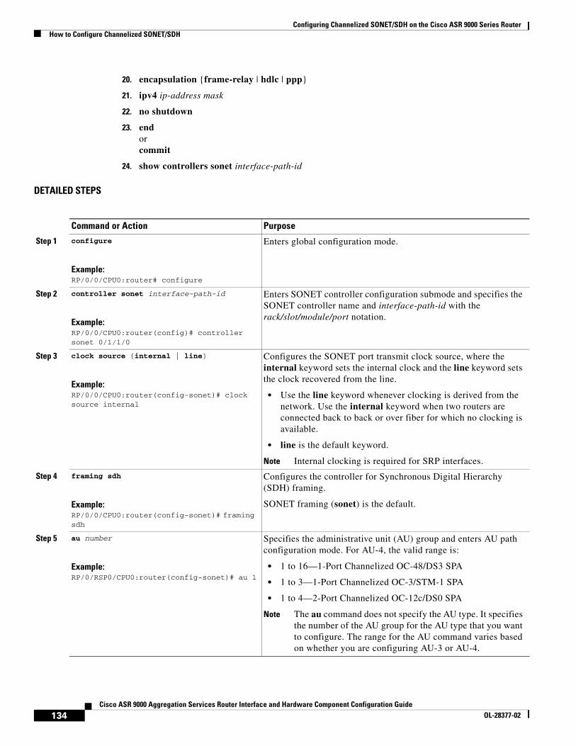
20. encapsulation {frame-relay | hdlc | ppp}
21. ipv4 ip-address mask
22. no shutdown
23. end or commit
24. show controllers sonet interface-path-id
DETAILED STEPS
Command or Action Purpose
Step 1 configure
Example:RP/0/0/CPU0:router# configure
Enters global configuration mode.
Step 2 controller sonet interface-path-id
Example:RP/0/0/CPU0:router(config)# controller sonet 0/1/1/0
Enters SONET controller configuration submode and specifies the SONET controller name and interface-path-id with the rack/slot/module/port notation.
Step 3 clock source {internal | line}
Example:RP/0/0/CPU0:router(config-sonet)# clock source internal
Configures the SONET port transmit clock source, where the internal keyword sets the internal clock and the line keyword sets the clock recovered from the line.
• Use the line keyword whenever clocking is derived from the network. Use the internal keyword when two routers are connected back to back or over fiber for which no clocking is available.
• line is the default keyword.
Note Internal clocking is required for SRP interfaces.
Step 4 framing sdh
Example:RP/0/0/CPU0:router(config-sonet)# framing sdh
Configures the controller for Synchronous Digital Hierarchy (SDH) framing.
SONET framing (sonet) is the default.
Step 5 au number
Example:RP/0/RSP0/CPU0:router(config-sonet)# au 1
Specifies the administrative unit (AU) group and enters AU path configuration mode. For AU-4, the valid range is:
• 1 to 16—1-Port Channelized OC-48/DS3 SPA
• 1 to 3—1-Port Channelized OC-3/STM-1 SPA
• 1 to 4—2-Port Channelized OC-12c/DS0 SPA
Note The au command does not specify the AU type. It specifies the number of the AU group for the AU type that you want to configure. The range for the AU command varies based on whether you are configuring AU-3 or AU-4.
134Cisco ASR 9000 Aggregation Services Router Interface and Hardware Component Configuration Guide
OL-28377-02
Configuring Channelized SONET/SDH on the Cisco ASR 9000 Series RouterHow to Configure Channelized SONET/SDH
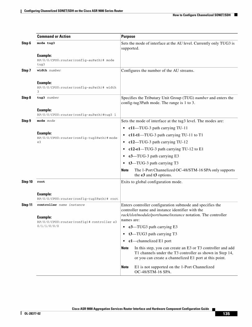
Step 6 mode tug3
Example:RP/0/0/CPU0:router(config-auPath)# mode tug3
Sets the mode of interface at the AU level. Currently only TUG3 is supported.
Step 7 width number
Example:RP/0/0/CPU0:router(config-auPath)# width 3
Configures the number of the AU streams.
Step 8 tug3 number
Example:RP/0/0/CPU0:router(config-auPath)#tug3 1
Specifies the Tributary Unit Group (TUG) number and enters the config-tug3Path mode. The range is 1 to 3.
Step 9 mode mode
Example:RP/0/0/CPU0:router(config-tug3Path)# mode e3
Sets the mode of interface at the tug3 level. The modes are:
• c11—TUG-3 path carrying TU-11
• c11-t1—TUG-3 path carrying TU-11 to T1
• c12—TUG-3 path carrying TU-12
• c12-e1—TUG-3 path carrying TU-12 to E1
• e3—TUG-3 path carrying E3
• t3—TUG-3 path carrying T3
Note The 1-Port Channelized OC-48/STM-16 SPA only supports the e3 and t3 options.
Step 10 root
Example:RP/0/0/CPU0:router(config-tug3Path)# root
Exits to global configuration mode.
Step 11 controller name instance
Example:RP/0/0/CPU0:router(config)# controller e3 0/1/1/0/0/0
Enters controller configuration submode and specifies the controller name and instance identifier with the rack/slot/module/port/name/instance notation. The controller names are:
• e3—TUG3 path carrying E3
• t3—TUG3 path carrying T3
• e1—channelized E1 port
Note In this step, you can create an E3 or T3 controller and add T1 channels under the T3 controller as shown in Step 14, or you can create a channelized E1 port at this point.
Note E1 is not supported on the 1-Port Channelized OC-48/STM-16 SPA.
Command or Action Purpose
135Cisco ASR 9000 Aggregation Services Router Interface and Hardware Component Configuration Guide
OL-28377-02

Configuring Channelized SONET/SDH on the Cisco ASR 9000 Series RouterHow to Configure Channelized SONET/SDH
Step 12 mode mode
Example:RP/0/0/CPU0:router(config-e3)#mode e1
Sets the mode of interface. The modes are:
• e1—Channelized into 21 E1s
• serial—Clear Channel carrying HDLC-like payload
• t1—Channelized into 28 T1s
Note T1 and E1 are not supported on the 1-Port Channelized OC-48/STM-16 SPA.
Step 13 root
Example:RP/0/0/CPU0:router(config-e3)# root
Exits to global configuration mode.
Step 14 controller name instance
Example:RP/0/0/CPU0:router(config)# controller E1 0/1/1/0/0/0/0/0
Enters controller configuration submode and specifies the controller name and instance identifier with the rack/slot/module/port/name/instance1/instance2 notation. The controller names are:
• serial—Clear Channel carrying HDLC-like payload.
• t1—Channelized into 24 T1s.
Step 15 channel-group number
Example:RP/0/0/CPU0:router(config-e1)# channel-group 0
Sets the channel-group number to which time slots are assigned.
• For t1, the range is from 1 to 24.
• For e1, the range is from 1 to 32.
Step 16 timeslots num1:num2:num3:num4 ortimeslots range1-range2
Example:RP/0/0/CPU0:router(config-e1-channel_group)# timeslots 1:3:7:9RP/0/0/CPU0:router(config-e1-channel_group)# timeslots 1-12
Specifies time slots for the interface by number with the num1:num2:num3:num4 notation, or by range with the range1-range2 notation.
Step 17 show configuration
Example:RP/0/0/CPU0:router(config-e1-channel_group)# show configuration
Displays the contents of uncommitted configuration.
Step 18 root
Example:RP/0/0/CPU0:router(config-e1-channel_group)# root
Exits to global configuration mode.
Step 19 interface serial interface-path-id
Example:RP/0/0/CPU0:router(config)# interface serial 0/1/1/0/0/0:0
Specifies the complete interface number with the rack/slot/module/port/T3Num/T1num:instance notation.
Command or Action Purpose
136Cisco ASR 9000 Aggregation Services Router Interface and Hardware Component Configuration Guide
OL-28377-02

Configuring Channelized SONET/SDH on the Cisco ASR 9000 Series RouterHow to Configure Channelized SONET/SDH
Step 20 encapsulation {frame-relay | hdlc | ppp}
Example:Router(config-if)# encapsulation frame-relay | hdlc | ppp
Specifies the encapsulation type with the one of the following keywords:
• frame-relay—Frame Relay network protocol
• hdlc—High-level Data Link Control (HDLC) synchronous protocol
• ppp—Point-to-Point Protocol
Step 21 ipv4 ip-address mask
Example:Router(config-if)# ip address 10.10.10.10 255.255.255.255
Assigns an IP address and subnet mask to the interface.
Step 22 no shutdown
Example:RP/0/0/CPU0:router (config-if)# no shutdown
Removes the shutdown configuration.
Note Removal of the shutdown configuration eliminates the forced administrative down on the interface, enabling it to move to an up or down state (assuming that the parent SONET layer is not configured administratively down).
Step 23 end
or
commit
Example:RP/0/0/CPU0:router(config-sonet)# end
or
RP/0/0/CPU0:router(config-sonet)# commit
Saves configuration changes.
• When you issue the end command, the system prompts you to commit changes:
Uncommitted changes found, commit them before exiting(yes/no/cancel)? [cancel]:
– Entering yes saves configuration changes to the running configuration file, exits the configuration session, and returns the router to EXEC mode.
– Entering no exits the configuration session and returns the router to EXEC mode without committing the configuration changes.
– Entering cancel leaves the router in the current configuration session without exiting or committing the configuration changes.
• Use the commit command to save the configuration changes to the running configuration file and remain within the configuration session.
Step 24 show controllers sonet interface-path-id
Example:RP/0/0/CPU0:router# show controllers sonet 0/1/1/0
Verifies the SONET controller configuration.
Command or Action Purpose
137Cisco ASR 9000 Aggregation Services Router Interface and Hardware Component Configuration Guide
OL-28377-02

Configuring Channelized SONET/SDH on the Cisco ASR 9000 Series RouterConfiguration Examples for Channelized SONET
Configuration Examples for Channelized SONETThis section contains the following examples:
• Channelized SONET Examples, page 38
• Channelized SDH Examples, page 40
Channelized SONET Examples• Channelized SONET T3 to T1 Configuration: Example, page 38
• Channelized Packet over SONET Configuration: Example, page 39
• SONET Clear Channel T3 Configuration: Example, page 39
• Channelized SONET APS Multirouter Configuration: Example, page 39
Channelized SONET T3 to T1 Configuration: Example
The following example shows SONET T3 to T1 configuration.
configure controller sonet 0/1/1/0 clock source internal framing sonet sts 1 mode t3 width 3 root controller t3 0/1/1/0/0 mode t1 root controller t1 0/1/1/0/0/0 framing esf channel-group 0 timeslots 1:3:7:9
show configuration root interface serial 0/1/1/0/0/0:0 encapsulation hdlc ip address 10.10.10.10 255.255.255.255 no shutdown commitshow controllers sonet 0/1/1/0
Channelized SONET in VT1.5 Mode and T1 Channelization to NxDS0
Note This example is not supported on the 1-Port Channelized OC-48/STM-16 SPA.
The following example shows how to configure SONET channelized to NxDS0s through SONET VT1.5 mode:
configure controller sonet 0/1/1/0 clock source internal framing sonet
138Cisco ASR 9000 Aggregation Services Router Interface and Hardware Component Configuration Guide
OL-28377-02
Configuring Channelized SONET/SDH on the Cisco ASR 9000 Series RouterConfiguration Examples for Channelized SONET
sts 1 mode vt15-t1
rootcontroller t1 0/1/1/0/0/0
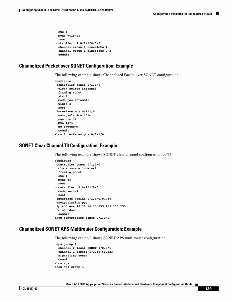
channel-group 0 timeslots 1channel-group 1 timeslots 2-3commit
Channelized Packet over SONET Configuration: Example
The following example shows Channelized Packet over SONET configuration.
configure controller sonet 0/1/1/0 clock source internal framing sonet sts 1 mode pos scramble width 3 root interface POS 0/1/1/0 encapsulation hdlc pos crc 32 mtu 4474 no shutdown commitshow interfaces pos 0/1/1/0
SONET Clear Channel T3 Configuration: Example
The following example shows SONET clear channel configuration for T3:
configure controller sonet 0/1/1/0 clock source internal framing sonet sts 1 mode t3 root controller t3 0/1/1/0/0 mode serial root interface serial 0/1/1/0/0/0:0 encapsulation ppp ip address 10.10.10.10 255.255.255.255 no shutdown commitshow controllers sonet 0/1/1/0
Channelized SONET APS Multirouter Configuration: Example
The following example shows SONET APS multirouter configuration.
aps group 1 channel 0 local SONET 0/0/0/1 channel 1 remote 172.18.69.123 signalling sonet commitshow apsshow aps group 3
139Cisco ASR 9000 Aggregation Services Router Interface and Hardware Component Configuration Guide
OL-28377-02

Configuring Channelized SONET/SDH on the Cisco ASR 9000 Series RouterConfiguration Examples for Channelized SONET
Channelized SDH Examples• Channelized SDH AU-3 Configuration: Examples, page 40
• Channelized SDH AU-4 Configuration: Examples, page 41
Channelized SDH AU-3 Configuration: Examples
This section includes the following configuration examples:
• Channelized SDH AU-3 to VC-3 and Clear Channel T3/E3: Examples, page 40
• Channelized SDH AU-3 to TUG-2, VC-11, T1 and NxDS0s: Example, page 40
• Channelized SDH AU-3 to TUG-2, VC-12, E1 and NxDS0s: Example, page 41
Channelized SDH AU-3 to VC-3 and Clear Channel T3/E3: Examples
The following example shows how to configure SDH AU-3 to VC-3 and clear channel T3:
configure controller sonet 0/1/1/0 clock source internal framing sdh au 1
width 1mode t3root
controller t3 0/1/1/0/1mode serialcommit
The following example shows how to configure SDH AU-3 to VC-3 and clear channel E3:
configure controller sonet 0/1/1/0 clock source internal framing sdh au 1
width 1mode e3root
controller e3 0/1/1/0/1mode serialcommit
Channelized SDH AU-3 to TUG-2, VC-11, T1 and NxDS0s: Example
Note This example is not supported on the 1-Port Channelized OC-48/STM-16 SPA.
The following example shows how to configure SDH AU-3 to TUG-2, VC-11 and channelized T1 to NxDS0s:
configure controller sonet 0/1/1/0 clock source internal framing sdh au 1
140Cisco ASR 9000 Aggregation Services Router Interface and Hardware Component Configuration Guide
OL-28377-02
Configuring Channelized SONET/SDH on the Cisco ASR 9000 Series RouterConfiguration Examples for Channelized SONET
mode c11-t1 width 1
root controller T1 0/1/1/0/0/1/1 channel-group 0 timeslots 1-12 show configuration root interface serial 0/1/1/0/1/1:0 encapsulation ppp ip address 10.10.10.10 255.255.255.255 no shutdown commitshow controllers sonet 0/1/1/0
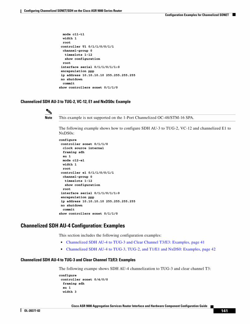
Channelized SDH AU-3 to TUG-2, VC-12, E1 and NxDS0s: Example
Note This example is not supported on the 1-Port Channelized OC-48/STM-16 SPA.
The following example shows how to configure SDH AU-3 to TUG-2, VC-12 and channelized E1 to NxDS0s:
configure controller sonet 0/1/1/0 clock source internal framing sdh au 1 mode c12-e1
width 1 root controller e1 0/1/1/0/0/1/1 channel-group 0 timeslots 1-12 show configuration root interface serial 0/1/1/0/1/1:0 encapsulation ppp ip address 10.10.10.10 255.255.255.255 no shutdown commitshow controllers sonet 0/1/1/0
Channelized SDH AU-4 Configuration: Examples
This section includes the following configuration examples:
• Channelized SDH AU-4 to TUG-3 and Clear Channel T3/E3: Examples, page 41
• Channelized SDH AU-4 to TUG-3, TUG-2, and T1/E1 and NxDS0: Examples, page 42
Channelized SDH AU-4 to TUG-3 and Clear Channel T3/E3: Examples
The following exampe shows SDH AU-4 channelization to TUG-3 and clear channel T3:
configurecontroller sonet 0/4/0/0framing sdhau 1width 3
141Cisco ASR 9000 Aggregation Services Router Interface and Hardware Component Configuration Guide
OL-28377-02

Configuring Channelized SONET/SDH on the Cisco ASR 9000 Series RouterConfiguration Examples for Channelized SONET
mode tug3 tug3 1 mode t3
rootcontroller t3 0/4/0/0/1/1mode serialcommit
The following exampe shows SDH AU-4 channelization to TUG-3 and clear channel E3:
configurecontroller sonet 0/4/0/0framing sdhau 1width 3
mode tug3 tug3 1 mode e3
rootcontroller e3 0/4/0/0/1/1mode serialcommit
Channelized SDH AU-4 to TUG-3, TUG-2, and T1/E1 and NxDS0: Examples
Note Channelization to T1/E1 and NxDS0s is not supported on the 1-Port Channelized OC-48/STM-16 SPA.
The following example shows SDH AU-4 configuration with unframed E1 controllers and serial interfaces:
configurecontroller sonet 0/1/2/0framing sdhau 1width 3
mode tug3 tug3 1 mode c12-e1! tug3 2 mode c12-e1! tug3 3 mode c12-e1!controller E1 0/1/2/0/1/1/1/1framing unframed!controller E1 0/1/2/0/1/1/1/2framing unframed!controller E1 0/1/2/0/1/1/1/3framing unframed!interface Serial0/1/2/0/1/1/1/1:0encapsulation pppmultilink group 1!interface Serial0/1/2/0/1/1/1/2:0encapsulation ppp
142Cisco ASR 9000 Aggregation Services Router Interface and Hardware Component Configuration Guide
OL-28377-02
Configuring Channelized SONET/SDH on the Cisco ASR 9000 Series RouterConfiguration Examples for Channelized SONET
multilink group 1!!interface Serial0/1/2/0/1/1/1/3:0encapsulation pppmultilink group 1!
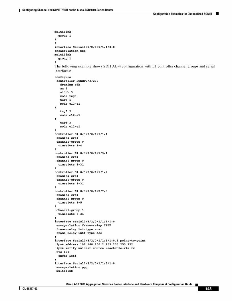
The following example shows SDH AU-4 configuration with E1 controller channel groups and serial interfaces:
configurecontroller SONET0/3/2/0
framing sdhau 1width 3
mode tug3 tug3 1
mode c12-e1!
tug3 2 mode c12-e1!
tug3 3 mode c12-e1!controller E1 0/3/2/0/1/1/1/1framing crc4channel-group 0timeslots 1-4
!controller E1 0/3/2/0/1/1/3/1framing crc4channel-group 0timeslots 1-31
!controller E1 0/3/2/0/1/1/1/2framing crc4channel-group 0
timeslots 1-31!controller E1 0/3/2/0/1/2/7/3framing crc4channel-group 0timeslots 1-5
!channel-group 1timeslots 6-31
!interface Serial0/3/2/0/1/1/1/1:0encapsulation frame-relay IETFframe-relay lmi-type ansiframe-relay intf-type dce
!interface Serial0/3/2/0/1/1/1/1:0.1 point-to-pointipv4 address 192.168.200.2 255.255.255.252ipv4 verify unicast source reachable-via rxpvc 100
encap ietf!interface Serial0/3/2/0/1/1/3/1:0encapsulation pppmultilink
143Cisco ASR 9000 Aggregation Services Router Interface and Hardware Component Configuration Guide
OL-28377-02

Configuring Channelized SONET/SDH on the Cisco ASR 9000 Series RouterAdditional References
group 1!interface Serial0/3/2/0/1/1/1/2:0encapsulation pppmultilink
group 1
Additional ReferencesThe following sections provide references related to channelized SONET configuration.
Related Documents
Standards
Related Topic Document Title
Cisco IOS XR master command reference Cisco IOS XR Master Commands List
Cisco IOS XR interface configuration commands Cisco IOS XR Interface and Hardware Component Command Reference
Initial system bootup and configuration information for a router using the Cisco IOS XR software
Cisco IOS XR Getting Started Guide
Information about user groups and task IDs Configuring AAA Services on Cisco IOS XR Software module of Cisco IOS XR System Security Configuration Guide
Standards Title
No new or modified standards are supported by this feature, and support for existing standards has not been modified by this feature.
—
144Cisco ASR 9000 Aggregation Services Router Interface and Hardware Component Configuration Guide
OL-28377-02

Configuring Channelized SONET/SDH on the Cisco ASR 9000 Series RouterAdditional References
MIBs
RFCs
Technical Assistance
MIBs MIBs Link
• CISCO-SONET-MIB
• ENTITY-MIB
• SONET-MIB (RFC 3592)
The following additional MIBs are supported on the Cisco 1-Port Channelized OC-3/STM-1 SPA and Cisco 2-Port Channelized OC-12c/DS0 SPA on the Cisco ASR 9000 Series Router:
• CISCO-IF-EXTENSION-MIB
• DS1-MIB
• DS3-MIB
• IF-MIB
To locate and download MIBs for selected platforms using Cisco IOS XR software, use the Cisco MIB Locator found at the following URL:
http://cisco.com/public/sw-center/netmgmt/cmtk/mibs.shtml
RFCs Title
No new or modified RFCs are supported by this feature, and support for existing RFCs has not been modified by this feature.
—
Description Link
The Cisco Technical Support website contains thousands of pages of searchable technical content, including links to products, technologies, solutions, technical tips, and tools. Registered Cisco.com users can log in from this page to access even more content.
http://www.cisco.com/techsupport
145Cisco ASR 9000 Aggregation Services Router Interface and Hardware Component Configuration Guide
OL-28377-02
Configuring Channelized SONET/SDH on the Cisco ASR 9000 Series RouterAdditional References
146Cisco ASR 9000 Aggregation Services Router Interface and Hardware Component Configuration Guide
OL-28377-02