galaxy sonet/sdh radio
TRANSCRIPT

Galaxy, Oct 9, 2000, #1 next level solutions 25-Oct-04
Galaxy18, 23, 28, 38 GHz
High CapacityPoint to Point Radio
High bandwidth for access & fiber extensions

Galaxy, Oct 9, 2000, #2 next level solutions 25-Oct-04
Broadband AccessPoint-to-point
SONET/SDH Access RadioSONET/SDH Access Radio
SONET/SDH Transport RadioSONET/SDH Transport Radio
Ideal for high bandwidth (155mbps) access & fiber extension applications
• Short - medium length hops• Congested urban environments• Stringent zoning restricted areas• High capacity wireless connectivity between base station transceivers

Galaxy, Oct 9, 2000, #3 next level solutions 25-Oct-04
Product Solution
• High Frequency/High Capacity SONET/SDH Radio
• Compact, All-Outdoor Package• Reliable, Superior Performance• Local Radio Configuration by
Wireless LAN• Single Integrated Cable Interface• Compatible Interfaces for 3G,
CLEC, ISP, VPN• Industry Standard SNMP Interface• Low Power Consumption
GalaxyGalaxy™™

Galaxy, Oct 9, 2000, #4 next level solutions 25-Oct-04
MCD Point-to-PointProduct portfolio
MicroStar® L/M/H
2 136 7/8 15 18 23 3826
1.5 / 2.0 Mbps
155 Mbps
NetBoss & StarView/SNMP Proxy Network Management
11 GHz7/8 GHz5/6 GHz
MegaStar® 155
N x 155 Mbps 1:N
Aurora™ 2400
52 Mbps
Constellation
GHz11
Aurora™ 5800MicroStar® E
Galaxy

Galaxy, Oct 9, 2000, #5 next level solutions 25-Oct-04
Design Evolution
Reduced RF development time Leveraging existing design
Unit cost reduced through use of common materials & packaging
Capital investment reduced bymodifying existing ATE & utilizing
established manufacturing process
MicroStarMicroStar--MM GalaxyGalaxy16 Months

Galaxy, Oct 9, 2000, #6 next level solutions 25-Oct-04
GalaxyProduct Line Features
• Product Line Features•ITU Frequency Plans:
• 18 GHz (55 MHz Spacing)• 23 GHz, 26 GHz, 38 GHz (56 MHz Spacing)
• 155 Mbps (STS-3 or STM1, optical or electrical)• Optional Access Interface Unit
•• TwoTwo Protected E1/10Base-T Bridge Wayside Channels• 10Base-T• Payload Access• NMS• Data Service Channel• External Alarms Outdoor Unit with Integrated
Flat Panel Antenna
Optional Access Interface Unit
Laptop Computer Craft Interface with2.4 GHz Wireless PCMCIA Card

Galaxy, Oct 9, 2000, #7 next level solutions 25-Oct-04
Galaxy Antenna options
• Integrated Flat Panel Antenna• Integrated Parabolic• Split-Mount Parabolic• Network Combiner (MHSB w/Single Antenna)
Alternatives for Every Installation
Integrated Flat Panel Antenna
Network Combiner
Integrated Parabolic Antenna Split Mount Parabolic

Galaxy, Oct 9, 2000, #8 next level solutions 25-Oct-04
Galaxy Interconnect Cable Interfaces
In-Line Adapter: Fiber InterfaceIn-Line Adapter: Coax Interface
Rack Mount Cable Adapter : Coax Interface
To DC Power
Cable Adapter
• Cable Adapter interfaces the Outdoor Unit to DC Power and premises equipment
• Mounted conveniently• Not environmentally sealed• Fiber and Coax Cables are available
To Customer Mux

Galaxy, Oct 9, 2000, #9 next level solutions 25-Oct-04
Optional GalaxyAIU - NP Configuration
E1 WaysideBalanced
E1Wayside
Unbalanced
10Base-TNMS &
Wayside (1)
RS-232Data Channel, NMS
SCAN, VT100
155 MBpsPayload
Test Point
External Alarms
•• TwoTwo Protected E1 Wayside Channels• 10Base-T• Payload Access Test Point
• NMS• Data Service Channel• External Alarms (8 Site Alarms
and 8 Remote Controls)
Galaxy, Oct 9, 2000, #10 next level solutions 25-Oct-04
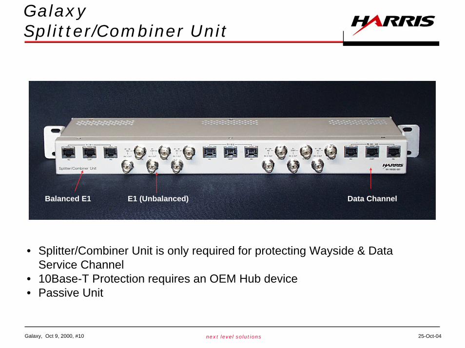
GalaxySplitter/Combiner Unit
Balanced E1 E1 (Unbalanced) Data Channel
• Splitter/Combiner Unit is only required for protecting Wayside & Data Service Channel
• 10Base-T Protection requires an OEM Hub device• Passive Unit

Galaxy, Oct 9, 2000, #11 next level solutions 25-Oct-04
Galaxy AIU - MHSB Configuration w/Splitter/Combiner Unit

Galaxy, Oct 9, 2000, #12 next level solutions 25-Oct-04
Galaxy - MHSB AIU Configuration w/Splitter/Combiner & Cables
• Galaxy units communicate over the wireless interface to mute theoff-line unit
• Protection is not errorless• Single antenna MHSB option• Replacement of ODU or AIU w/o affecting
traffic
Galaxy, Oct 9, 2000, #13 next level solutions 25-Oct-04
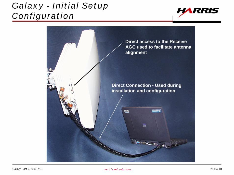
Galaxy - Initial Setup Configuration
Direct Connection - Used during installation and configuration
Direct access to the Receive AGC used to facilitate antenna alignment

Galaxy, Oct 9, 2000, #14 next level solutions 25-Oct-04
GalaxyWLAN CIT Configuration
Aironet/Cisco WLAN Type II Card(Order as Accessory)
• Wireless CIT access using 2.4 GHz Spread Spectrum interface
• Uses Wireless Equivalent Privacy (WEP) IEEE 802.11 for secure connection
• Access is password protected
• Remote access of up to 300 m depending on obstructions
• Enables Service Provider maintenance personnel to connect to the Galaxy without requiring access to the customer building
• Radio repair requires only roof access

Galaxy, Oct 9, 2000, #15 next level solutions 25-Oct-04
GalaxyCIT Alarm & Status Screen
• IP Radio addressing - “Point and Click”• Full network access for comprehensive
fault isolation

Galaxy, Oct 9, 2000, #16 next level solutions 25-Oct-04
GalaxyCIT NMS Screen
• “Drag and Drop” modification of NMS Bytes eliminates equipment incompatibility
Galaxy, Oct 9, 2000, #17 next level solutions 25-Oct-04
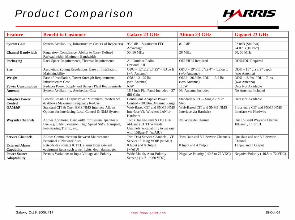
Product Comparison
Feature Benefit to Customer Galaxy 23 GHz Altium 23 GHz Giganet 23 GHz System Gain System Availability, Infrastructure Cost (# of Repeaters) 95.0 dB – Significant FEC
Advantage 81.0 dB 92.0dB (Std Pwr)
94.0 dB (Hi Pwr) Channel Bandwidth Regulatory Compliance, Ability to Carry Defined
Payload within Minimum Bandwidth 50, 56 MHz 28 MHz 50, 56 MHz
Packaging Rack Space Requirements, Thermal Requirements All-Outdoor Radio Optional AIU
ODU/IDU Required ODU/IDU Required
Size Aesthetics, Zoning Regulations, Ease of Installation, Maintainability
ODU – 12”x12”x7.25” - .63 cu ft (w/o Antenna)
ODU – 19”x11.8”x9.4” – 1.2 cu ft (w/o Antenna)
ODU – 10” dia x 9” depth (w/o Antenna)
Weight Ease of Installation, Tower Strength Requirements, Infrastructure Cost
ODU – 21.25 lbs (w/o Antenna)
ODU – 36.3 lbs IDU – 13.2 lbs (w/o Antenna)
ODU - 18 lbs IDU – 7 lbs (w/o Antenna)
Power Consumption Reduces Power Supply and Battery Plant Requirements 60W 110W Data Not Available Antenna System Availability, Aesthetics, Cost 16.5 inch Flat Panel Included - 37
dBi Gain No Antenna Included No Antenna Included
Adaptive Power Control
Lowest Possible Output Power Minimizes Interference & Allows Maximum Frequency Re-Use
Continuous Adaptive Power Control – 30dBm Dynamic Range
Standard ATPC – Single 7 dBm Step
Data Not Available
OAM&P Standard CIT & Open EMS/NMS Interface Allows Options for Interfacing Local Control & NMS System
Web-Based CIT and SNMP NMS Interface Via Wireless LAN or Hardwire
Web-Based CIT and SNMP NMS Interface via Hardwire
Proprietary CIT and SNMP NMS Interface via Hardwire
Wayside Channels Allows Additional Bandwidth for System Operator’s Use, e.g. LAN Extension, High Speed NMS Transport, Fee-Bearing Traffic, etc.
Two (One In-Band & One Out-of-Band) E1/T1 Wayside Channels w/capability to use one with 10Base-T (w/AIU)
No Wayside Channel One In-Band Wayside Channel 10BaseT, T1 or E1
Service Channels Allows Communication Between Maintenance Personnel at Network Sites
Two Data Service Channels - VF Service if Using VOIP (w/AIU)
Two Data and VF Service Channels One data and one VF Service Channel
External Alarm Capability
Extends dry contact & TTL alarms from external equipment items such tower lights, door alarms, etc.
8 Input and 8 Output (w/AIU)
8 Input and 4 Output 1 Input and 5 Output
Power Source Adaptability
Permits Variations to Input Voltage and Polarity Wide-Mouth, Auto-Polarity Sensing (+/-21 to 60 VDC)
Negative Polarity (-40.5 to 72 VDC) Negative Polarity (-40.5 to 72 VDC)
Galaxy, Oct 9, 2000, #18 next level solutions 25-Oct-04
Q&A