test report no.: 1-8297/14-02-05-b testing laboratory ... · pdf fileumts: 826.4 – 846.6...
TRANSCRIPT

TEST REPORT
Test report no.: 1-8297/14-02-05-B
Testing laboratory Applicant
CETECOM ICT Services GmbH
Untertuerkheimer Strasse 6 – 10 66117 Saarbruecken / Germany Phone: + 49 681 5 98 - 0 Fax: + 49 681 5 98 - 9075 Internet: http://www.cetecom.com e-mail: [email protected]
Accredited Testing Laboratory:
The testing laboratory (area of testing) is accredited according to DIN EN ISO/IEC 17025 (2005) by the Deutsche Akkreditierungsstelle GmbH (DAkkS) The accreditation is valid for the scope of testing procedures as stated in the accreditation certificate with the registration number: D-PL-12076-01-00
peiker acustic GmbH & Co. KG
Max-Planck Str. 28-32 61381 Friedrichsdorf / GERMANY Phone: -/- Fax: +49 6172 767-220 Contact: Martin Fleckenstein e-mail: [email protected] Phone: +49 6172 767-1379
Manufacturer
peiker acustic GmbH & Co. KG
Max-Planck Str. 28-32 61381 Friedrichsdorf / GERMANY
Test standard/s
47 CFR Part 22 Title 47 of the Code of Federal Regulations; Chapter I; Part 22 - Public mobile services
47 CFR Part 24 Title 47 of the Code of Federal Regulations; Chapter I; Part 24 - Personal communications services
For further applied test standards please refer to section 3 of this test report.
Test Item
Kind of test item: Advanced Telecommunication module (ATM) Roof Version
Model name: ATM-01 R1-US-4GW
FCC ID: QWY-ATM-R-522
IC: 6588A-ATMR522
Frequency: GSM: 824.2 – 848.8 MHz, 1850.2 – 1909.8 MHz UMTS: 826.4 – 846.6 MHz, 1852.4 – 1907.6 MHz
Technology tested: GSM / EDGE, UMTS
Antenna: External and internal antenna
Power supply: 14.0 V DC by external power supply
Temperature range: -30°C to +60°C
This test report is electronically signed and valid without handwriting signature. For verification of the electronic signatures, the public keys can be requested at the testing laboratory.
Test report authorised: Test performed:
p.o.
Andreas Luckenbill Marco Bertolino Radio Communications & EMC Radio Communications & EMC

Test report no.: 1-8297/14-02-05-B
Page 2 of 56
1 Table of contents
1 Table of contents ............................................................................................................................................ 2
2 General information ....................................................................................................................................... 3
2.1 Notes and disclaimer .......................................................................................................................... 3 2.2 Application details ............................................................................................................................... 3
3 Test standard/s ............................................................................................................................................... 3
4 Test environment ............................................................................................................................................ 4
5 Test item .......................................................................................................................................................... 4
5.1 Additional information ........................................................................................................................ 4
6 Test laboratories sub-contracted ................................................................................................................. 4
7 Summary of measurement results ............................................................................................................... 5
7.1 GSM 850 ................................................................................................................................................ 5 7.2 PCS 1900 .............................................................................................................................................. 5 7.3 UMTS band II ........................................................................................................................................ 6 7.4 UMTS band V........................................................................................................................................ 6
8 RF measurements .......................................................................................................................................... 7
8.1 Description of test setup .................................................................................................................... 7 8.1.1 Radiated measurements .................................................................................................................... 7 8.1.2 Conducted measurements ................................................................................................................. 8 8.2 Results GSM 850 ................................................................................................................................. 9 8.2.1 RF output power ................................................................................................................................ 9 8.2.2 Spurious emissions radiated ............................................................................................................ 11 8.2.3 Block edge compliance .................................................................................................................... 17 8.3 Results PCS 1900 .............................................................................................................................. 20 8.3.1 RF output power .............................................................................................................................. 20 8.3.2 Spurious emissions radiated ............................................................................................................ 22 8.3.3 Block edge compliance .................................................................................................................... 30 8.4 Results UMTS band II ........................................................................................................................ 33 8.4.1 RF output power .............................................................................................................................. 33 8.4.2 Spurious emissions radiated ............................................................................................................ 35 8.4.3 Block edge compliance .................................................................................................................... 42 8.5 Results UMTS band V ....................................................................................................................... 44 8.5.1 RF output power .............................................................................................................................. 44 8.5.2 Spurious emissions radiated ............................................................................................................ 46 8.5.3 Block edge compliance .................................................................................................................... 51
9 Test equipment and ancillaries used for tests .......................................................................................... 53
10 Observations ............................................................................................................................................. 54
Annex A Document history .......................................................................................................................... 55
Annex B Further information ........................................................................................................................ 55
Annex C Accreditation Certificate ............................................................................................................... 56

Test report no.: 1-8297/14-02-05-B
Page 3 of 56
2 General information
2.1 Notes and disclaimer The test results of this test report relate exclusively to the test item specified in this test report. CETECOM ICT Services GmbH does not assume responsibility for any conclusions and generalizations drawn from the test results with regard to other specimens or samples of the type of the equipment represented by the test item. The test report may only be reproduced or published in full. Reproduction or publication of extracts from the report requires the prior written approval of CETECOM ICT Services GmbH. The testing service provided by CETECOM ICT Services GmbH has been rendered under the current "General Terms and Conditions for CETECOM ICT Services GmbH". CETECOM ICT Services GmbH will not be liable for any loss or damage resulting from false, inaccurate, inappropriate or incomplete product information provided by the customer. Under no circumstances does the CETECOM ICT Services GmbH test report include any endorsement or warranty regarding the functionality, quality or performance of any other product or service provided. Under no circumstances does the CETECOM ICT Services GmbH test report include or imply any product or service warranties from CETECOM ICT Services GmbH, including, without limitation, any implied warranties of merchantability, fitness for purpose, or non-infringement, all of which are expressly disclaimed by CETECOM ICT Services GmbH. All rights and remedies regarding vendor’s products and services for which CETECOM ICT Services GmbH has prepared this test report shall be provided by the party offering such products or services and not by CETECOM ICT Services GmbH. In no case this test report can be considered as a Letter of Approval. This test report is electronically signed and valid without handwritten signature. For verification of the electronic signatures, the public keys can be requested at the testing laboratory.
2.2 Application details Date of receipt of order: 2014-12-19 Date of receipt of test item: 2015-02-17 Start of test: 2015-02-17 End of test: 2015-02-24 Person(s) present during the test: -/-
3 Test standard/s Test standard Date Test standard description 47 CFR Part 22 -/- Title 47 of the Code of Federal Regulations; Chapter I; Part 22 -
Public mobile services
47 CFR Part 24 -/- Title 47 of the Code of Federal Regulations; Chapter I; Part 24 - Personal communications services
RSS - 132 Issue 3 01.01.2013 Spectrum Management and Telecommunications Radio Standards Specification - Cellular Telephone Systems Operating in the Bands 824-849 MHz and 869-894 MHz
RSS - 133 Issue 6 01.01.2013 Spectrum Management and Telecommunications Policy - Radio Standards Specifications, 2 GHz Personal Communication Services

Test report no.: 1-8297/14-02-05-B
Page 4 of 56
4 Test environment
Temperature: Tnom Tmax Tmin
+22 °C during room temperature tests +60 °C during high temperature tests -30 °C during low temperature tests
Relative humidity content: 42 %
Barometric pressure: not relevant for this kind of testing
Power supply: Vnom Vmax Vmin
14.0 V DC by external power supply 18.0 V 4.5 V
5 Test item
Kind of test item : Advanced Telecommunication module (ATM) Roof Version
HVIN : ATM-01 R1-US-4GW
PMN : ATM roof version
S/N serial number : Radiated / conducted unit: 0000506765
HW hardware status : 112.010.016
SW software status : 001.017.047
Frequency band : GSM: 824.2 – 848.8 MHz, 1850.2 – 1909.8 MHz
UMTS: 826.4 – 846.6 MHz, 1852.4 – 1907.6 MHz
Type of modulation : GMSK, 8-PSK, QPSK
Antenna : External and internal antenna
Power supply : 14.0 V DC by external power supply
Temperature range : -30°C to +60°C
5.1 Additional information The content of the following annexes is defined in the QA. It may be that not all of the listed annexes are necessary for this report, thus some values in between may be missing. Test setup- and EUT-photos are included in test report: 1-8297/14-02-01_AnnexA
1-8297/14-02-01_AnnexB 1-8297/14-02-01_AnnexC
6 Test laboratories sub-contracted None

Test report no.: 1-8297/14-02-05-B
Page 5 of 56
7 Summary of measurement results
No deviations from the technical specifications were ascertained
There were deviations from the technical specifications ascertained
X This test report is only a partial test report. The content and verdict of the performed test cases are listed below.
TC identifier Description verdict date Remark
RF-Testing CFR Part 22, 24 RSS 132, 133
See table! 2015-06-16
Tests according to manufacturer
test plan.
7.1 GSM 850
Test Case temperature conditions
power source voltages
Pass Fail NA NP Remark
RF Output Power Nominal Nominal complies
Frequency Stability Nominal Nominal -/-
Spurious Emissions Radiated
Nominal Nominal complies
Spurious Emissions Conducted
Nominal Nominal -/-
Block Edge Compliance Nominal Nominal complies
Occupied Bandwidth Nominal Nominal -/-
Note: NA = Not applicable; NP = Not performed
7.2 PCS 1900
Test Case temperature conditions
power source voltages
Pass Fail NA NP Remark
RF Output Power Nominal Nominal complies
Frequency Stability Nominal Nominal -/-
Spurious Emissions Radiated
Nominal Nominal complies
Spurious Emissions Conducted
Nominal Nominal -/-
Block Edge Compliance Nominal Nominal complies
Occupied Bandwidth Nominal Nominal -/-
Note: NA = Not applicable; NP = Not performed

Test report no.: 1-8297/14-02-05-B
Page 6 of 56
7.3 UMTS band II
Test Case temperature conditions
power source voltages
Pass Fail NA NP Remark
RF Output Power Nominal Nominal complies
Frequency Stability Nominal Nominal -/-
Spurious Emissions Radiated
Nominal Nominal complies
Spurious Emissions Conducted
Nominal Nominal -/-
Block Edge Compliance Nominal Nominal complies
Occupied Bandwidth Nominal Nominal -/-
Note: NA = Not applicable; NP = Not performed
7.4 UMTS band V
Test Case temperature conditions
power source voltages
Pass Fail NA NP Remark
RF Output Power Nominal Nominal complies
Frequency Stability Nominal Nominal -/-
Spurious Emissions Radiated
Nominal Nominal complies
Spurious Emissions Conducted
Nominal Nominal -/-
Block Edge Compliance Nominal Nominal complies
Occupied Bandwidth Nominal Nominal -/-
Note: NA = Not applicable; NP = Not performed

Test report no.: 1-8297/14-02-05-B
Page 7 of 56
8 RF measurements
8.1 Description of test setup For the spurious measurements we use the substitution method according TIA/EIA 603.
8.1.1 Radiated measurements The radiated emissions from the EUT are performed in a semi anechoic chamber. The EUT is placed on a conductive turntable and powered with nominal voltage. The signalling is performed either from outside the chamber with a signalling unit (AP or other) by air link using a signalling antenna or directly by special test software from the customer. Semi anechoic chamber
Picture 1: Diagram radiated measurements
9 kHz - 30 MHz: active loop antenna 30 MHz – 1 GHz: tri-log antenna > 1 GHz: horn antenna
Frequency being measured f
Measuring receiver bandwidth 6 dB
Spectrum analyser bandwidth 3dB
f < 150 kHz 200 Hz or 300 Hz
150 kHz ≤ f < 25 MHz 9 kHz or 10 kHz
25 MHz ≤ f < 1000 MHz 120 kHz or 100 kHz
1000 MHz ≤ f 1 MHz
NOTE: Specific requirements in CEPT/ERC/Recommendation 70-03 [2] shall be applied where applicable.

Test report no.: 1-8297/14-02-05-B
Page 8 of 56
8.1.2 Conducted measurements The EUT’s RF signal is coupled out by the antenna connector which is supplied by the manufacturer. The signal is first 10dB attenuated before it is power divided (~6dB loss per branch). One of the signal paths is connected to the signalling unit (AP or other), the other one is connected to the spectrum analyzer. The specific losses for both signal paths are first checked within a calibration. The measurement readings on the signalling unit/spectrum analyzer are corrected by the specific test set-up loss. The attenuator, power divider, signalling unit and the spectrum analyzer are impedance matched on 50 Ohm. If special software is used, there is no power divider necessary.
Picture 2: Diagram conducted measurements
The term measuring receiver refers to either a selective voltmeter or a spectrum analyser.
Frequency being measured f
Measuring receiver bandwidth 6 dB
Spectrum analyser bandwidth 3dB
f < 150 kHz 200 Hz or 300 Hz
150 kHz ≤ f < 25 MHz 9 kHz or 10 kHz
25 MHz ≤ f < 1000 MHz 120 kHz or 100 kHz
1000 MHz ≤ f 1 MHz
NOTE: Specific requirements in CEPT/ERC/Recommendation 70-03 [2] shall be applied where applicable.

Test report no.: 1-8297/14-02-05-B
Page 9 of 56
8.2 Results GSM 850 All GSM-band measurements are done in GSM mode only (circuit switched). All relevant tests have been repeated using 8-PSK modulation if EDGE mode is supported. All tests were performed with one timeslot in uplink activated and one timeslot in downlink activated. For each mode the highest output power was determined and used.
8.2.1 RF output power Description: This paragraph contains average power, peak output power and ERP measurements for the mobile station. In all cases, the peak output power is within the required mask (this mask is specified in the JTC standards, TIA PN3389 Vol. 1 Chap 7, and is no FCC requirement). Measurement: The mobile was set up for the maximum output power with pseudo random data modulation.
Measurement parameters
Detector: Peak and RMS (Power in Burst)
Sweep time: Auto
Video bandwidth: 1 MHz
Resolution bandwidth: 1 MHz
Span: Zero Span
Trace-Mode: Max Hold
Limits:
FCC IC
CFR Part 22.913 CFR Part 2.1046
RSS 132
Nominal Peak Output Power
+38.45 dBm In measuring transmissions in this band using an average power technique, the peak-to-average ratio (PAR) of the
transmission may not exceed 13 dB.
Used setup acc. chapter 8.1.2. Used equipment see table chapter 9

Test report no.: 1-8297/14-02-05-B
Page 10 of 56
Results:
Output Power (conducted) GMSK mode
Frequency (MHz) Average Output Power (dBm) Peak to Average Ratio (dB)
824.2 32.2 0.03
836.4 31.8 0.04
848.8 32.0 0.03
Measurement uncertainty ± 0.5 dB
Output Power (conducted) 8-PSK mode
Frequency (MHz) Average Output Power (dBm) Peak to Average Ratio (dB)
824.2 26.5 3.16
836.4 26.3 3.33
848.8 26.4 3.23
Measurement uncertainty ± 0.5 dB
Output Power (radiated) GMSK mode
Frequency (MHz) Average Output Power (dBm) - ERP
824.2 (external antenna) 28.76
836.4 (external antenna) 27.31
848.8 (external antenna) 26.36
848.8 (internal antenna) 28.58
Measurement uncertainty ± 2.0 dB
Output Power (radiated) 8-PSK mode
Frequency (MHz) Average Output Power (dBm) - ERP
824.2 (external antenna) 23.06
836.4 (external antenna) 21.81
848.8 (external antenna) 20.76
848.8 (internal antenna) 22.98
Measurement uncertainty ± 2.0 dB
Verdict: complies

Test report no.: 1-8297/14-02-05-B
Page 11 of 56
8.2.2 Spurious emissions radiated Description: The following steps outline the procedure used to measure the radiated emissions from the mobile station. The site is constructed in accordance with ANSI C63.4:2014 requirements and is recognized by the FCC to be in compliance for a 3 and a 10 meter site. The spectrum was scanned from 30 MHz to the 10th harmonic of the highest frequency generated within the equipment, which is the transmitted carrier that can be as high as 848.8 MHz. This was rounded up to 12 GHz. The resolution bandwidth is set as outlined in Part 22.917. The spectrum was scanned with the mobile station transmitting at carrier frequencies that pertain to low, mid and high channels of the GSM-850 band. The final open field emission (here 10m semi-anechoic chamber listed by FCC) test procedure is as follows: a) The test item was placed on a 0.8 meter high non-conductive stand at a 3 meter test distance from the receive antenna. b) The antenna output was terminated in a 50 ohm load (if possible). c) A double ridged wave guide antenna was placed on an adjustable height antenna mast 3 meters from the test item for emission measurements. d) Detected emissions were maximized at each frequency by rotating the test item and adjusting the receive antenna height and polarization. The maximum meter reading was recorded. The radiated emission measurements of the harmonics of the transmit frequency through the 10th harmonic were measured with peak detector and 1 MHz bandwidth. If the harmonic could not be detected above the noise floor, the ambient level was recorded. The equivalent power into a dipole antenna was calculated from the field intensity levels measured at 3 meters. e) Now each detected emissions were substituted by the substitution method, in accordance with the TIA/EIA 603. Measurement:
Measurement parameters
Detector: Peak
Sweep time: 2 sec.
Video bandwidth: Below 1 GHz: 100 kHz Above 1 GHz: 1 MHz
Resolution bandwidth: Below 1 GHz: 100 kHz Above 1 GHz: 1 MHz
Span: 100 MHz Steps
Trace-Mode: Max Hold
Limits:
FCC IC
CFR Part 22.917 CFR Part 2.1053
RSS 132
Spurious Emissions Radiated
Attenuation ≥ 43 + 10log(P) (P, Power in Watts)
-13 dBm
Used setup acc. chapter 8.1.1. Used equipment see table chapter 9

Test report no.: 1-8297/14-02-05-B
Page 12 of 56
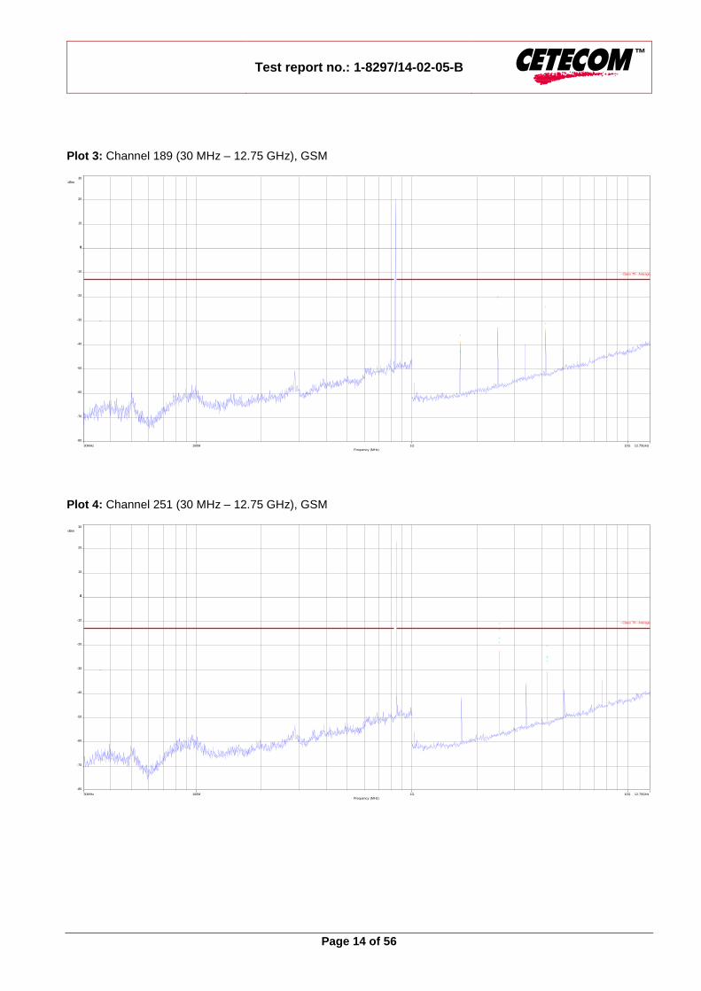
Results: Radiated emissions measurements were made only at the upper, center, and lower carrier frequencies of the GSM-850 band (824.2 MHz, 836.4 MHz and 848.8 MHz). It was decided that measurements at these three carrier frequencies would be sufficient to demonstrate compliance with emissions limits because it was seen that all the significant spurs occur well outside the band and no radiation was seen from a carrier in one block of the GSM-850 band into any of the other blocks. The equipment must still, however, meet emissions requirements with the carrier at all frequencies over which it is capable of operating and it is the manufacturer's responsibility to verify this. The final open field radiated levels are presented on the next pages. All measurements were done in horizontal and vertical polarization; the plots show the worst case. The plots show only the middle channel. If spurious were detected, the lowest and highest channel were checked too. The found values are stated in the table below. As can be seen from this data, the emissions from the test item were within the specification limit.
Spurious Emission Level (dBm)
Harmonic Ch. 128
Freq. (MHz) Level [dBm]
Harmonic Ch. 189
Freq. (MHz) Level [dBm]
Harmonic Ch. 251
Freq. (MHz) Level [dBm]
2 1648.4 -35.4 (peak) 2 1672.8 -34.1 (peak) 2 1697.6 GSM
-9.5 (peak) -20.47 (AVG)
-/- -/- 2 1697.6 Edge
-10.2 (peak) -13.2 (AVG)
3 2472.6 -44.7 (peak) 3 2509.2 -19.2 (peak) 3 2546.4 -
4 3296.8 - 4 3345.6 - 4 3395.2 -
5 4121.0 - 5 4182.0 -23.1 (peak) 5 4244.0 -20.6 (peak)
6 4945.2 - 6 5018.4 - 6 5092.8 -
7 5769.4 - 7 5854.8 - 7 5941.6 -
8 6593.6 - 8 6691.2 - 8 6790.4 -
9 7417.8 - 9 7527.6 - 9 7639.2 -
10 8242.0 - 10 8364.0 - 10 8488.0 -
Measurement uncertainty ± 3dB
Verdict: complies

Test report no.: 1-8297/14-02-05-B
Page 13 of 56
Plots: (external antenna) Plot 1: Channel 189 (Traffic mode up to 30 MHz), GSM
Plot 2: Channel 128 (30 MHz – 12.75 GHz), GSM
9kHz 30MHz10M1M100k
Frequency (MHz)
0
130
dBµV/m
110
80
50
20
100
70
40
10
120
90
60
30
- Class - Peak
- Class - QPeak
- Class - Average
30MHz 12.75GHz10G1G100M
Frequency (MHz)
-80
30
dBm
0 0
-50
-20
20
-70
-40
-10
10
-60
-30
- Class TX - Average
Test report no.: 1-8297/14-02-05-B
Page 14 of 56
Plot 3: Channel 189 (30 MHz – 12.75 GHz), GSM
Plot 4: Channel 251 (30 MHz – 12.75 GHz), GSM
30MHz 12.75GHz10G1G100M
Frequency (MHz)
-80
30
dBm
0 0
-50
-20
20
-70
-40
-10
10
-60
-30
- Class TX - Average
30MHz 12.75GHz10G1G100M
Frequency (MHz)
-80
30
dBm
0 0
-50
-20
20
-70
-40
-10
10
-60
-30
- Class TX - Average

Test report no.: 1-8297/14-02-05-B
Page 15 of 56
Plot 5: Channel 251 (30 MHz – 12.75 GHz), EDGE
30MHz 12.75GHz10G1G100M
Frequency (MHz)
-80
30
dBm
0 0
-50
-20
20
-70
-40
-10
10
-60
-30
- Class TX - Average

Test report no.: 1-8297/14-02-05-B
Page 16 of 56
Plots: (internal antenna) Plot 1: Channel 251 (Traffic mode up to 30 MHz), GSM
Plot 2: Channel 251 (30 MHz – 12.75 GHz), GSM
9kHz 30MHz10M1M100k
Frequency (MHz)
0
130
dBµV/m
110
80
50
20
100
70
40
10
120
90
60
30
- Class - Peak
- Class - QPeak
- Class - Average
30MHz 12.75GHz10G1G100M
Frequency (MHz)
-80
30
dBm
0 0
-50
-20
20
-70
-40
-10
10
-60
-30
- Class TX - Average

Test report no.: 1-8297/14-02-05-B
Page 17 of 56
8.2.3 Block edge compliance Description: The spectrum at the band edges must comply with the spurious emissions limits. Measurement:
Measurement parameters
Detector: RMS
Sweep time: Auto
Video bandwidth: 3 kHz
Resolution bandwidth: 3 kHz
Span: 1 MHz
Trace-Mode: Max Hold
Limits:
FCC IC
CFR Part 22.917 CFR Part 2.1051
RSS 132
Block Edge Compliance
Attenuation ≥ 43 + 10log(P) (P, Power in Watts)
-13 dBm
Used setup acc. chapter 8.1.2. Used equipment see table chapter 9

Test report no.: 1-8297/14-02-05-B
Page 18 of 56
Plots: Plot 1: Channel 128 (GSM-mode)
Plot 2: Channel 251 (GSM-mode)

Test report no.: 1-8297/14-02-05-B
Page 19 of 56
Plot 3: Channel 128 (EDGE-mode)
Plot 4: Channel 251 (EDGE-mode)
Verdict: complies

Test report no.: 1-8297/14-02-05-B
Page 20 of 56
8.3 Results PCS 1900 All GSM-band measurements are done in GSM mode only (circuit switched). All relevant tests have been repeated using 8-PSK modulation if EDGE mode is supported. All tests were performed with one timeslot in uplink activated and one timeslot in downlink activated. For each mode the highest output power was determined and used.
8.3.1 RF output power Description: This paragraph contains average power, peak output power and EIRP measurements for the mobile station. In all cases, the peak output power is within the required mask (this mask is specified in the JTC standards, TIA PN3389 Vol. 1 Chap 7, and is no FCC requirement). Measurement: The mobile was set up for the maximum output power with pseudo random data modulation.
Measurement parameters
Detector: Peak and RMS (Power in Burst)
Sweep time: Auto
Video bandwidth: 1 MHz
Resolution bandwidth: 1 MHz
Span: Zero Span
Trace-Mode: Max Hold
Limits:
FCC IC
CFR Part 24.232 CFR Part 2.1046
RSS 133
Nominal Peak Output Power
+33.00 dBm In measuring transmissions in this band using an average power technique, the peak-to-average ratio (PAR) of the
transmission may not exceed 13 dB.
Used setup acc. chapter 8.1.2. Used equipment see table chapter 9

Test report no.: 1-8297/14-02-05-B
Page 21 of 56
Results:
Output Power (conducted) GMSK mode
Frequency (MHz) Average Output Power (dBm) Peak to Average Ratio (dB)
1850.2 29.7 0.06
1880.0 30.1 0.04
1909.8 30.1 0.04
Measurement uncertainty ± 0.5 dB
Output Power (conducted) 8-PSK mode
Frequency (MHz) Average Output Power (dBm) Peak to Average Ratio (dB)
1850.2 25.9 3.09
1880.0 26.0 3.20
1909.8 25.6 3.41
Measurement uncertainty ± 0.5 dB
Output Power (radiated) GMSK mode
Frequency (MHz) Average Output Power (dBm) - EIRP
1850.2 (external antenna) 27.26
1880.0 (external antenna) 26.86
1909.8 (external antenna) 27.23
1909.8 (internal antenna) 32.35
Measurement uncertainty ± 2.0 dB
Output Power (radiated) 8-PSK mode
Frequency (MHz) Average Output Power (dBm) - EIRP
1850.2 (external antenna) 23.46
1880.0 (external antenna) 22.76
1909.8 (external antenna) 22.73
1909.8 (internal antenna) 27.85
Measurement uncertainty ± 2.0 dB
Verdict: complies

Test report no.: 1-8297/14-02-05-B
Page 22 of 56
8.3.2 Spurious emissions radiated Description: The following steps outline the procedure used to measure the radiated emissions from the mobile station. The site is constructed in accordance with ANSI C63.4:2014 requirements and is recognized by the FCC to be in compliance for a 3 and a 10 meter site. The spectrum was scanned from 30 MHz to the 10th harmonic of the highest frequency generated within the equipment, which is the transmitted carrier that can be as high as 1910 MHz. Measurement made up to 25 GHz. The resolution bandwidth is set as outlined in Part 24.238. The spectrum was scanned with the mobile station transmitting at carrier frequencies that pertain to low, mid and high channels of the PCS1900 band. The final open field emission (here 10m semi-anechoic chamber listed by FCC) test procedure is as follows: a) The test item was placed on a 0.8 meter high non-conductive stand at a 3 meter test distance from the receive antenna. b) The antenna output was terminated in a 50 ohm load (if possible). c) A double ridged wave guide antenna was placed on an adjustable height antenna mast 3 meters from the test item for emission measurements. d) Detected emissions were maximized at each frequency by rotating the test item and adjusting the receive antenna height and polarization. The maximum meter reading was recorded. The radiated emission measurements of the harmonics of the transmit frequency through the 10th harmonic were measured with peak detector and 1 MHz bandwidth. If the harmonic could not be detected above the noise floor, the ambient level was recorded. The equivalent power into a dipole antenna was calculated from the field intensity levels measured at 3 meters. e) Now each detected emissions were substituted by the substitution method, in accordance with the TIA/EIA 603. Measurement:
Measurement parameters
Detector: Peak
Sweep time: 2 sec.
Video bandwidth: Below 1 GHz: 100 kHz Above 1 GHz: 1 MHz
Resolution bandwidth: Below 1 GHz: 100 kHz Above 1 GHz: 1 MHz
Span: 100 MHz Steps
Trace-Mode: Max Hold
Limits:
FCC IC
CFR Part 24.238 CFR Part 2.1053
RSS 133
Spurious Emissions Radiated
Attenuation ≥ 43 + 10log(P) (P, Power in Watts)
-13 dBm
Used setup acc. chapter 8.1.1. Used equipment see table chapter 9

Test report no.: 1-8297/14-02-05-B
Page 23 of 56
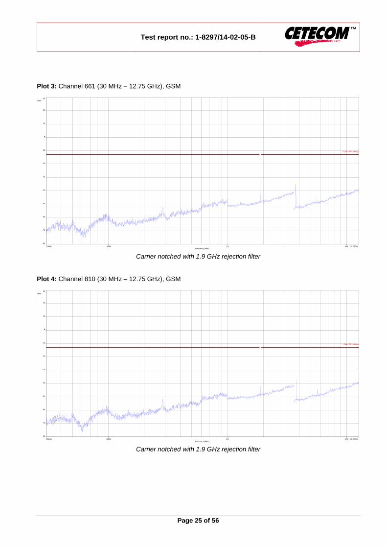
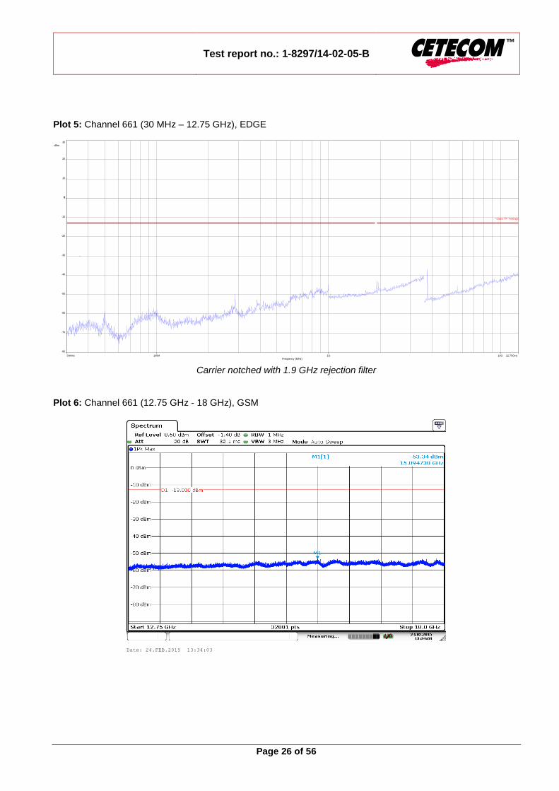
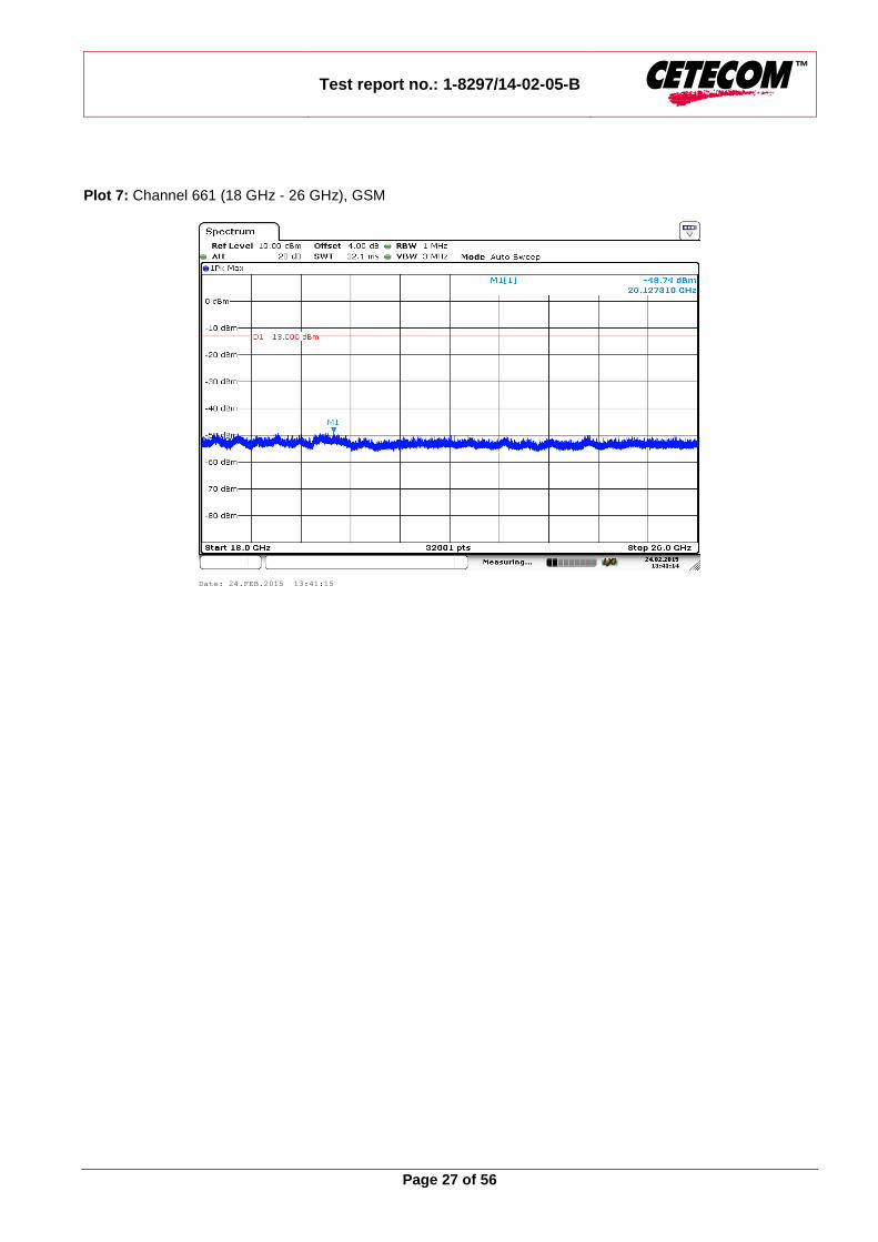
Results: Radiated emissions measurements were made only at the upper, center, and lower carrier frequencies of the PCS1900 band (1850.2 MHz, 1880.0 MHz and 1909.8 MHz). It was decided that measurements at these three carrier frequencies would be sufficient to demonstrate compliance with emissions limits because it was seen that all the significant spurs occur well outside the band and no radiation was seen from a carrier in one block of the PCS1900 band into any of the other blocks. The equipment must still, however, meet emissions requirements with the carrier at all frequencies over which it is capable of operating and it is the manufacturer's responsibility to verify this. The final open field radiated levels are presented on the next pages. All measurements were done in horizontal and vertical polarization; the plots show the worst case. The plots show only the middle channel. If spurious were detected, the lowest and highest channel were checked too. The found values are stated in the table below. As can be seen from this data, the emissions from the test item were within the specification limit.
Spurious Emission Level (dBm)
Harmonic Ch. 512
Freq. (MHz) Level [dBm]
Harmonic Ch. 661
Freq. (MHz) Level [dBm]
Harmonic Ch. 810
Freq. (MHz) Level [dBm]
2 3700.4 - 2 3760.0 - 2 3819.6 -
3 5550.6 - 3 5640.0 - 3 5729.4 -
4 7400.8 - 4 7520.0 - 4 7639.2 -
5 9251.0 - 5 9400.0 - 5 9549.0 -
6 11101.2 - 6 11280.0 - 6 11458.8 -
7 12951.4 - 7 13160.0 - 7 13368.6 -
8 14801.6 - 8 15040.0 - 8 15278.4 -
9 16651.8 - 9 16920.0 - 9 17188.2 -
10 18502.0 - 10 18800.0 - 10 19098.0 -
Measurement uncertainty ± 3dB
Verdict: complies

Test report no.: 1-8297/14-02-05-B
Page 24 of 56
Plots: (external antenna) Plot 1: Channel 661 (Traffic mode up to 30 MHz), GSM
Plot 2: Channel 512 (30 MHz – 12.75 GHz), GSM
Carrier notched with 1.9 GHz rejection filter
9kHz 30MHz10M1M100k
Frequency (MHz)
0
130
dBµV/m
110
80
50
20
100
70
40
10
120
90
60
30
- Class - Peak
- Class - QPeak
- Class - Average
30MHz 12.75GHz10G1G100M
Frequency (MHz)
-80
30
dBm
0 0
-50
-20
20
-70
-40
-10
10
-60
-30
- Class TX - Average
Test report no.: 1-8297/14-02-05-B
Page 25 of 56
Plot 3: Channel 661 (30 MHz – 12.75 GHz), GSM
Carrier notched with 1.9 GHz rejection filter
Plot 4: Channel 810 (30 MHz – 12.75 GHz), GSM
Carrier notched with 1.9 GHz rejection filter
30MHz 12.75GHz10G1G100M
Frequency (MHz)
-80
30
dBm
0 0
-50
-20
20
-70
-40
-10
10
-60
-30
- Class TX - Average
30MHz 12.75GHz10G1G100M
Frequency (MHz)
-80
30
dBm
0 0
-50
-20
20
-70
-40
-10
10
-60
-30
- Class TX - Average
Test report no.: 1-8297/14-02-05-B
Page 26 of 56
Plot 5: Channel 661 (30 MHz – 12.75 GHz), EDGE
Carrier notched with 1.9 GHz rejection filter
Plot 6: Channel 661 (12.75 GHz - 18 GHz), GSM
30MHz 12.75GHz10G1G100M
Frequency (MHz)
-80
30
dBm
0 0
-50
-20
20
-70
-40
-10
10
-60
-30
- Class TX - Average
Date: 24.FEB.2015 13:34:03
Test report no.: 1-8297/14-02-05-B
Page 27 of 56
Plot 7: Channel 661 (18 GHz - 26 GHz), GSM
Date: 24.FEB.2015 13:41:15

Test report no.: 1-8297/14-02-05-B
Page 28 of 56
Plots: (internal antenna) Plot 1: Channel 661 (Traffic mode up to 30 MHz), GSM
Plot 2: Channel 810 (30 MHz – 12.75 GHz), GSM
Carrier notched with 1.9 GHz rejection filter
9kHz 30MHz10M1M100k
Frequency (MHz)
0
130
dBµV/m
110
80
50
20
100
70
40
10
120
90
60
30
- Class - Peak
- Class - QPeak
- Class - Average
30MHz 12.75GHz10G1G100M
Frequency (MHz)
-80
30
dBm
0 0
-50
-20
20
-70
-40
-10
10
-60
-30
- Class TX - Average

Test report no.: 1-8297/14-02-05-B
Page 29 of 56
Plot 3: Channel 661 (12.75 GHz - 18 GHz), GSM
Plot 4: Channel 661 (18 GHz - 26 GHz), GSM
Date: 24.FEB.2015 13:37:26
Date: 24.FEB.2015 13:43:28

Test report no.: 1-8297/14-02-05-B
Page 30 of 56
8.3.3 Block edge compliance Description: The spectrum at the band edges must comply with the spurious emissions limits. Measurement:
Measurement parameters
Detector: RMS
Sweep time: Auto
Video bandwidth: 3 kHz
Resolution bandwidth: 3 kHz
Span: 1 MHz
Trace-Mode: Max Hold
Limits:
FCC IC
CFR Part 24.238 CFR Part 2.1051
RSS 133
Block Edge Compliance
Attenuation ≥ 43 + 10log(P) (P, Power in Watts)
-13 dBm
Used setup acc. chapter 8.1.2. Used equipment see table chapter 9

Test report no.: 1-8297/14-02-05-B
Page 31 of 56
Plots: Plot 1: Channel 512 (GSM-mode)
Plot 2: Channel 810 (GSM-mode)

Test report no.: 1-8297/14-02-05-B
Page 32 of 56
Plot 3: Channel 512 (EDGE-mode)
Plot 4: Channel 810 (EDGE-mode)
Verdict: complies

Test report no.: 1-8297/14-02-05-B
Page 33 of 56
8.4 Results UMTS band II All UMTS-band measurements are done in WCDMA mode only. The connection was established with the following setup: WCDMA CS-RMC, Max Power (All Bit up)
8.4.1 RF output power Description: This paragraph contains average power, peak output power and EIRP measurements for the mobile station. In all cases, the peak output power is within the required mask (this mask is specified in the JTC standards, TIA PN3389 Vol. 1 Chap 7, and is no FCC requirement). Measurement: The mobile was set up for the maximum output power with pseudo random data modulation. To determine the Peak-To-Average Power Ratio (PAPR) the measurement was performed with the Power Complementary Cumulative Distribution Function (CCDF).
Measurement parameters
Detector: Peak and RMS (Power in Burst)
Sweep time: Auto
Video bandwidth: 10 MHz
Resolution bandwidth: 10 MHz
Span: Zero Span
Trace-Mode: Max Hold
Limits:
FCC IC
CFR Part 24.232 CFR Part 2.1046
RSS 133
Nominal Peak Output Power
+33.00 dBm In measuring transmissions in this band using an average power technique, the peak-to-average ratio (PAR) of the
transmission may not exceed 13 dB.
Used setup acc. chapter 8.1.2. Used equipment see table chapter 9

Test report no.: 1-8297/14-02-05-B
Page 34 of 56
Results:
Output Power (conducted) WCDMA mode
Frequency (MHz) Average Output Power (dBm) Peak to Average Ratio (dB)
1852.4 23.9 3.33
1880.0 23.7 3.45
1907.6 23.6 2.88
Measurement uncertainty ± 0.5 dB
Output Power (radiated) WCDMA mode
Frequency (MHz) Average Output Power (dBm) - EIRP
1852.4 (external antenna) 21.46
1880.0 (external antenna) 20.46
1907.6 (external antenna) 20.73
1907.6 (internal antenna) 25.85
Measurement uncertainty ± 2.0 dB
Verdict: complies

Test report no.: 1-8297/14-02-05-B
Page 35 of 56
8.4.2 Spurious emissions radiated Description: The following steps outline the procedure used to measure the radiated emissions from the mobile station. The site is constructed in accordance with ANSI C63.4:2014 requirements and is recognized by the FCC to be in compliance for a 3 and a 10 meter site. The spectrum was scanned from 30 MHz to the 10th harmonic of the highest frequency generated within the equipment, which is the transmitted carrier that can be as high as 1910 MHz. Measurement made up to 25 GHz. The resolution bandwidth is set as outlined in Part 24.238. The spectrum was scanned with the mobile station transmitting at carrier frequencies that pertain to low, mid and high channels of the UMTS band II. The final open field emission (here 10m semi-anechoic chamber listed by FCC) test procedure is as follows: a) The test item was placed on a 0.8 meter high non-conductive stand at a 3 meter test distance from the receive antenna. b) The antenna output was terminated in a 50 ohm load (if possible). c) A double ridged wave guide antenna was placed on an adjustable height antenna mast 3 meters from the test item for emission measurements. d) Detected emissions were maximized at each frequency by rotating the test item and adjusting the receive antenna height and polarization. The maximum meter reading was recorded. The radiated emission measurements of the harmonics of the transmit frequency through the 10th harmonic were measured with peak detector and 1 MHz bandwidth. If the harmonic could not be detected above the noise floor, the ambient level was recorded. The equivalent power into a dipole antenna was calculated from the field intensity levels measured at 3 meters. e) Now each detected emissions were substituted by the substitution method, in accordance with the TIA/EIA 603. Measurement:
Measurement parameters
Detector: Peak
Sweep time: 2 sec.
Video bandwidth: Below 1 GHz: 100 kHz Above 1 GHz: 1 MHz
Resolution bandwidth: Below 1 GHz: 100 kHz Above 1 GHz: 1 MHz
Span: 100 MHz Steps
Trace-Mode: Max Hold
Limits:
FCC IC
CFR Part 24.238 CFR Part 2.1053
RSS 133
Spurious Emissions Radiated
Attenuation ≥ 43 + 10log(P) (P, Power in Watts)
-13 dBm
Used setup acc. chapter 8.1.1. Used equipment see table chapter 9

Test report no.: 1-8297/14-02-05-B
Page 36 of 56
Results: Radiated emissions measurements were made only at the upper, center, and lower carrier frequencies of the UMTS band II (1852.4 MHz, 1880.0 MHz and 1907.6 MHz). It was decided that measurements at these three carrier frequencies would be sufficient to demonstrate compliance with emissions limits because it was seen that all the significant spurs occur well outside the band and no radiation was seen from a carrier in one block of the UMTS band II into any of the other blocks. The equipment must still, however, meet emissions requirements with the carrier at all frequencies over which it is capable of operating and it is the manufacturer's responsibility to verify this. The final open field radiated levels are presented on the next pages. All measurements were done in horizontal and vertical polarization; the plots show the worst case. The plots show only the middle channel. If spurious were detected, the lowest and highest channel were checked too. The found values are stated in the table below. As can be seen from this data, the emissions from the test item were within the specification limit.
Spurious Emission Level (dBm)
Harmonic Ch. 9262
Freq. (MHz) Level [dBm]
Harmonic Ch. 9400
Freq. (MHz) Level [dBm]
Harmonic Ch. 9538
Freq. (MHz) Level [dBm]
2 3704.8 -28.2
(ext. ant.) 2 3760.0
-29.2 (ext. ant.)
2 3815.2 -25.6
(ext. ant.)
3 5557.2 -33.5
(ext. ant.) 3 5640.0
-35.1 (ext. ant.)
3 5722.8 -31.6
(ext. ant.)
-/- -/- 2 3815.2 -20.3
(int. ant.)
-/- -/- 3 5722.8 -27.3
(int. ant.)
4 7409.6 - 4 7520.0 - 4 7630.4 -
5 9262.0 - 5 9400.0 - 5 9538.0 -
6 11114.4 - 6 11280.0 - 6 11445.6 -
7 12966.8 - 7 13160.0 - 7 13353.2 -
8 14819.2 - 8 15040.0 - 8 15260.8 -
9 16671.6 - 9 16920.0 - 9 17168.4 -
10 18524.0 - 10 18800.0 - 10 19076.0 -
Measurement uncertainty ± 3dB
Verdict: complies

Test report no.: 1-8297/14-02-05-B
Page 37 of 56
Plots: (external antenna) Plot 1: Channel 9400 (Traffic mode up to 30 MHz)
Plot 2: Channel 9262 (30 MHz – 12.75 GHz)
Carrier notched with 1.9 GHz rejection filter
9kHz 30MHz10M1M100k
Frequency (MHz)
0
130
dBµV/m
110
80
50
20
100
70
40
10
120
90
60
30
- Class - Peak
- Class - QPeak
- Class - Average
30MHz 12.75GHz10G1G100M
Frequency (MHz)
-80
30
dBm
0 0
-50
-20
20
-70
-40
-10
10
-60
-30
- Class TX - Average

Test report no.: 1-8297/14-02-05-B
Page 38 of 56
Plot 3: Channel 9400 (30 MHz – 12.75 GHz)
Carrier notched with 1.9 GHz rejection filter
Plot 4: Channel 9538 (30 MHz – 12.75 GHz)
Carrier notched with 1.9 GHz rejection filter
30MHz 12.75GHz10G1G100M
Frequency (MHz)
-80
30
dBm
0 0
-50
-20
20
-70
-40
-10
10
-60
-30
- Class TX - Average
30MHz 12.75GHz10G1G100M
Frequency (MHz)
-80
30
dBm
0 0
-50
-20
20
-70
-40
-10
10
-60
-30
- Class TX - Average

Test report no.: 1-8297/14-02-05-B
Page 39 of 56
Plot 5: Channel 9400 (12.75 GHz - 18 GHz)
Plot 6: Channel 9400 (18 GHz - 26 GHz)
Date: 24.FEB.2015 13:38:39
Date: 24.FEB.2015 13:45:20

Test report no.: 1-8297/14-02-05-B
Page 40 of 56
Plots: (internal antenna) Plot 1: Channel 9538 (Traffic mode up to 30 MHz)
Plot 2: Channel 9538 (30 MHz – 12.75 GHz)
Carrier notched with 1.9 GHz rejection filter
9kHz 30MHz10M1M100k
Frequency (MHz)
0
130
dBµV/m
110
80
50
20
100
70
40
10
120
90
60
30
- Class - Peak
- Class - QPeak
- Class - Average
30MHz 12.75GHz10G1G100M
Frequency (MHz)
-80
30
dBm
0 0
-50
-20
20
-70
-40
-10
10
-60
-30
- Class TX - Average

Test report no.: 1-8297/14-02-05-B
Page 41 of 56
Plot 3: Channel 9538 (12.75 GHz - 18 GHz)
Plot 4: Channel 9538 (18 GHz - 26 GHz)
Date: 24.FEB.2015 14:28:22
Date: 24.FEB.2015 14:26:45

Test report no.: 1-8297/14-02-05-B
Page 42 of 56
8.4.3 Block edge compliance Description: The spectrum at the band edges must comply with the spurious emissions limits. Measurement:
Measurement parameters
Detector: RMS
Sweep time: 20 sec.
Video bandwidth: 30 kHz
Resolution bandwidth: 30 kHz
Span: 1 MHz
Trace-Mode: Max Hold
Limits:
FCC IC
CFR Part 24.238 CFR Part 2.1051
RSS 133
Block Edge Compliance
Part 24.238 specifies that “the power of any emission outside of the authorized operating frequency ranges must be attenuated below the transmitting power (P) by a factor of at least 43 + 10 log(P) dB.”
However, in publication number 890810, The FCC Office of Engineering and Technology specified the following
correction to the limits when a resolution bandwidth smaller than 1% of the emission bandwidth is used:
“An alternative is to add an additional correction factor of 10 Log (RBW1/ RBW2) to the 43 +10 Log (P) limit. RBW1 is the narrower measurement resolution bandwidth and RBW2 is either the 1% emissions bandwidth or 1 MHz.”
When using a 30 kHz bandwidth, this yields a -2.2185 adjustment to the limit [10log(30kHz/50kHz) = -2.2185]. When this
adjustment is applied to the limit, the limit becomes -15.2185.
-15.22 dBm
Used setup acc. chapter 8.1.2. Used equipment see table chapter 9

Test report no.: 1-8297/14-02-05-B
Page 43 of 56
Plots: Plot 1: Channel 9262
Plot 2: Channel 9538
Verdict: complies

Test report no.: 1-8297/14-02-05-B
Page 44 of 56
8.5 Results UMTS band V All UMTS-band measurements are done in WCDMA mode only. The connection was established with the following setup: WCDMA CS-RMC, Max Power (All Bit up)
8.5.1 RF output power Description: This paragraph contains average power, peak output power and ERP measurements for the mobile station. In all cases, the peak output power is within the required mask (this mask is specified in the JTC standards, TIA PN3389 Vol. 1 Chap 7, and is no FCC requirement). Measurement: The mobile was set up for the maximum output power with pseudo random data modulation. To determine the Peak-To-Average Power Ratio (PAPR) the measurement was performed with the Power Complementary Cumulative Distribution Function (CCDF).
Measurement parameters
Detector: Peak and RMS (Power in Burst)
Sweep time: Auto
Video bandwidth: 10 MHz
Resolution bandwidth: 10 MHz
Span: Zero Span
Trace-Mode: Max Hold
Limits:
FCC IC
CFR Part 22.913 CFR Part 2.1046
RSS 132
Nominal Peak Output Power
+38.45 dBm In measuring transmissions in this band using an average power technique, the peak-to-average ratio (PAR) of the
transmission may not exceed 13 dB.
Used setup acc. chapter 8.1.2. Used equipment see table chapter 9

Test report no.: 1-8297/14-02-05-B
Page 45 of 56
Results:
Output Power (conducted) WCDMA mode
Frequency (MHz) Average Output Power (dBm) Peak to Average Ratio (dB)
826.4 22.9 3.37
836.0 22.6 3.60
846.6 23.2 3.42
Measurement uncertainty ± 0.5 dB
Output Power (radiated) WCDMA mode
Frequency (MHz) Average Output Power (dBm) - ERP
826.4 (external antenna) 19.46
836.0 (external antenna) 18.11
846.6 (external antenna) 17.56
846.6 (internal antenna) 19.78
Measurement uncertainty ± 2.0 dB
Verdict: complies

Test report no.: 1-8297/14-02-05-B
Page 46 of 56
8.5.2 Spurious emissions radiated Description: The following steps outline the procedure used to measure the radiated emissions from the mobile station. The site is constructed in accordance with ANSI C63.4:2014 requirements and is recognized by the FCC to be in compliance for a 3 and a 10 meter site. The spectrum was scanned from 30 MHz to the 10th harmonic of the highest frequency generated within the equipment, which is the transmitted carrier that can be as high as 846.6 MHz. Measurement made up to 12.75 GHz. The resolution bandwidth is set as outlined in Part 22.917. The spectrum was scanned with the mobile station transmitting at carrier frequencies that pertain to low, mid and high channels of the UMTS band V. The final open field emission (here 10m semi-anechoic chamber listed by FCC) test procedure is as follows: a) The test item was placed on a 0.8 meter high non-conductive stand at a 3 meter test distance from the receive antenna. b) The antenna output was terminated in a 50 ohm load (if possible). c) A double ridged wave guide antenna was placed on an adjustable height antenna mast 3 meters from the test item for emission measurements. d) Detected emissions were maximized at each frequency by rotating the test item and adjusting the receive antenna height and polarization. The maximum meter reading was recorded. The radiated emission measurements of the harmonics of the transmit frequency through the 10th harmonic were measured with peak detector and 1 MHz bandwidth. If the harmonic could not be detected above the noise floor, the ambient level was recorded. The equivalent power into a dipole antenna was calculated from the field intensity levels measured at 3 meters. e) Now each detected emissions were substituted by the substitution method, in accordance with the TIA/EIA 603. Measurement:
Measurement parameters
Detector: Peak
Sweep time: 2 sec.
Video bandwidth: Below 1 GHz: 100 kHz Above 1 GHz: 1 MHz
Resolution bandwidth: Below 1 GHz: 100 kHz Above 1 GHz: 1 MHz
Span: 100 MHz Steps
Trace-Mode: Max Hold
Limits:
FCC IC
CFR Part 22.917 CFR Part 2.1053
RSS 132
Spurious Emissions Radiated
Attenuation ≥ 43 + 10log(P) (P, Power in Watts)
-13 dBm
Used setup acc. chapter 8.1.1. Used equipment see table chapter 9

Test report no.: 1-8297/14-02-05-B
Page 47 of 56
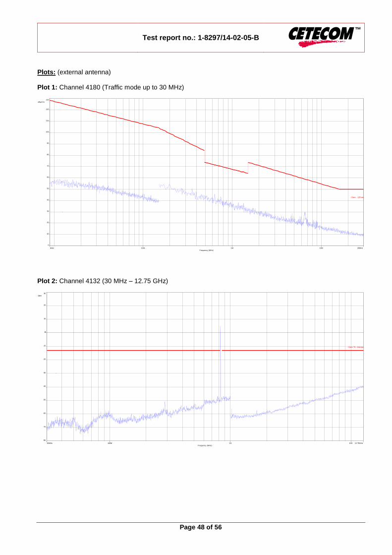
Results: Radiated emissions measurements were made only at the upper, center, and lower carrier frequencies of the UMTS band V (826.4 MHz, 836.0 MHz and 846.6 MHz). It was decided that measurements at these three carrier frequencies would be sufficient to demonstrate compliance with emissions limits because it was seen that all the significant spurs occur well outside the band and no radiation was seen from a carrier in one block of the UMTS band V into any of the other blocks. The equipment must still, however, meet emissions requirements with the carrier at all frequencies over which it is capable of operating and it is the manufacturer's responsibility to verify this. The final open field radiated levels are presented on the next pages. All measurements were done in horizontal and vertical polarization; the plots show the worst case. The plots show only the middle channel. If spurious were detected, the lowest and highest channel were checked too. The found values are stated in the table below. As can be seen from this data, the emissions from the test item were within the specification limit.
Spurious Emission Level (dBm)
Harmonic Ch. 4132
Freq. (MHz) Level [dBm]
Harmonic Ch. 4180
Freq. (MHz) Level [dBm]
Harmonic Ch. 4233
Freq. (MHz) Level [dBm]
2 1652.8 - 2 1672.0 - 2 1693.2 -
3 2479.2 - 3 2508.0 - 3 2539.8 -
4 3305.6 - 4 3344.0 - 4 3386.4 -
5 4132.0 - 5 4180.0 - 5 4233.0 -
6 4958.4 - 6 5016.0 - 6 5079.6 -
7 5784.8 - 7 5852.0 - 7 5926.2 -
8 6611.2 - 8 6688.0 - 8 6772.8 -
9 7437.6 - 9 7524.0 - 9 7619.4 -
10 8264.0 - 10 8360.0 - 10 8466.0 -
Measurement uncertainty ± 3dB
Verdict: complies
Test report no.: 1-8297/14-02-05-B
Page 48 of 56
Plots: (external antenna) Plot 1: Channel 4180 (Traffic mode up to 30 MHz)
Plot 2: Channel 4132 (30 MHz – 12.75 GHz)
9kHz 30MHz10M1M100k
Frequency (MHz)
0
130
dBµV/m
110
80
50
20
100
70
40
10
120
90
60
30
- Class - Peak
- Class - QPeak
- Class - Average
30MHz 12.75GHz10G1G100M
Frequency (MHz)
-80
30
dBm
0 0
-50
-20
20
-70
-40
-10
10
-60
-30
- Class TX - Average

Test report no.: 1-8297/14-02-05-B
Page 49 of 56
Plot 3: Channel 4180 (30 MHz – 12.75 GHz)
Plot 4: Channel 4233 (30 MHz – 12.75 GHz)
30MHz 12.75GHz10G1G100M
Frequency (MHz)
-80
30
dBm
0 0
-50
-20
20
-70
-40
-10
10
-60
-30
- Class TX - Average
30MHz 12.75GHz10G1G100M
Frequency (MHz)
-80
30
dBm
0 0
-50
-20
20
-70
-40
-10
10
-60
-30
- Class TX - Average

Test report no.: 1-8297/14-02-05-B
Page 50 of 56
Plots: (internal antenna) Plot 1: Channel 4233 (Traffic mode up to 30 MHz)
Plot 2: Channel 4233 (30 MHz – 12.75 GHz)
9kHz 30MHz10M1M100k
Frequency (MHz)
0
130
dBµV/m
110
80
50
20
100
70
40
10
120
90
60
30
- Class - Peak
- Class - QPeak
- Class - Average
30MHz 12.75GHz10G1G100M
Frequency (MHz)
-80
30
dBm
0 0
-50
-20
20
-70
-40
-10
10
-60
-30
- Class TX - Average

Test report no.: 1-8297/14-02-05-B
Page 51 of 56
8.5.3 Block edge compliance Description: The spectrum at the band edges must comply with the spurious emissions limits. Measurement:
Measurement parameters
Detector: RMS
Sweep time: 20 sec.
Video bandwidth: 30 kHz
Resolution bandwidth: 30 kHz
Span: 1 MHz
Trace-Mode: Max Hold
Limits:
FCC IC
CFR Part 22.917 CFR Part 2.1051
RSS 132
Block Edge Compliance
Part 22.917 specifies that “the power of any emission outside of the authorized operating frequency ranges must be attenuated below the transmitting power (P) by a factor of at least 43 + 10 log(P) dB.”
However, in publication number 890810, The FCC Office of Engineering and Technology specified the following
correction to the limits when a resolution bandwidth smaller than 1% of the emission bandwidth is used:
“An alternative is to add an additional correction factor of 10 Log (RBW1/ RBW2) to the 43 +10 log(P) limit. RBW1 is the narrower measurement resolution bandwidth and RBW2 is either the 1% emissions bandwidth or 1 MHz.”
When using a 30 kHz bandwidth, this yields a -2.2185 adjustment to the limit [10 log(30kHz/50kHz) = -2.2185]. When this
adjustment is applied to the limit, the limit becomes -15.2185.
-15.22 dBm
Used setup acc. chapter 8.1.2. Used equipment see table chapter 9

Test report no.: 1-8297/14-02-05-B
Page 52 of 56
Plots: Plot 1: Channel 4132
Plot 2: Channel 4233
Verdict: complies

Test report no.: 1-8297/14-02-05-B
Page 53 of 56
9 Test equipment and ancillaries used for tests Typically, the calibrations of the test apparatus are commissioned to and performed by an accredited calibration laboratory. The calibration intervals are determined in accordance with the DIN EN ISO/IEC 17025. In addition to the external calibrations, the laboratory executes comparison measurements with other calibrated test systems or effective verifications. Weekly chamber inspections and range calibrations are performed. Where possible, rf-generating and signalling equipment as well as measuring receivers and analyzers are connected to an external high-precision 10 MHz reference (GPS-based or rubidium frequency standard). In order to simplify the identification of the equipment used at some special tests, some items of test equipment and ancillaries can be provided with an identifier or number in the equipment list below (Lab/Item).
No. Lab / Item
Equipment Type Manufact. Serial No. INV. No Cetecom
Kind of Calibration
Last Calibration
Next Calibration
1 n. a. DC power supply, 60Vdc, 50A, 1200 W
6032A HP 2818A03450 300001040 Ve 20.01.2015 20.01.2018
2 n. a. Double-Ridged Waveguide Horn Antenna 1-18.0GHz
3115 EMCO 8812-3088 300001032 vlKI! 08.05.2013 08.05.2015
3 n. a. Anechoic chamber FAC 3/5m MWB / TDK 87400/02 300000996 ev
4 n. a. Switch / Control Unit 3488A HP * 300000199 ne
5 9 Artificial Mains 9 kHz to 30 MHz
ESH3-Z5 R&S 828576/020 300001210 Ve 30.01.2014 30.01.2016
6 9 Isolating Transformer
MPL IEC625 Bus Regeltrenntravo
Erfi 91350 300001155 ne
7 90 Active Loop Antenna 10 kHz to 30 MHz
6502 Kontron Psychotech 8905-2342 300000256 k 13.06.2013 13.06.2015
8 90 Amplifier js42-00502650-28-5a
Parzich GMBH 928979 300003143 ne
9 90 Band Reject filter WRCG1855/1910-1835/1925-40/8SS
Wainwright 7 300003350 ev
10 90 TRILOG Broadband Test-Antenna 30 MHz - 3 GHz
VULB9163 Schwarzbeck 371 300003854 vlKI! 29.10.2014 29.10.2017
11 90 MXE EMI Receiver 20 Hz to 26,5 GHz
N9038A Agilent Technologies MY51210197 300004405 k 13.03.2014 13.03.2015
12 n. a. Switch / Control Unit 3488A HP 2605e08770 300001443 ne
13 n. a. Signal Analyzer 20Hz-26,5GHz-150 to + 30 DBM
FSiQ26 R&S 835111/0004 300002678 Ve 22.01.2015 22.01.2017
14 n. a. Power Supply 0-20V; 0-5A
6632B HP US37478366 400000117 vlKI! 20.01.2015 20.01.2017
15 11b Microwave System Amplifier, 0.5-26.5 GHz
83017A HP 00419 300002268 ev
16 A026 Std. Gain Horn Antenna 12.4 to 18.0 GHz
639 Narda 8402 300000787 k 22.07.2013 22.07.2015
17 A029 Std. Gain Horn Antenna 18.0 to 26.5 GHz
638 Narda 8205 300002442 k 19.07.2013 19.07.2015
18 A029 Signal Analyzer 40 GHz
FSV40 R&S 101042 300004517 k 22.01.2015 22.01.2016
19 n. a. Universal Communication Tester
CMU200 R&S 106240 300003321 vlKI! 12.06.2013 12.06.2015
Agenda: Kind of Calibration
k calibration / calibrated EK limited calibration ne not required (k, ev, izw, zw not required) zw cyclical maintenance (external cyclical maintenance) ev periodic self verification izw internal cyclical maintenance Ve long-term stability recognized g blocked for accredited testing vlkI! Attention: extended calibration interval NK! Attention: not calibrated *) next calibration ordered / currently in progress

Test report no.: 1-8297/14-02-05-B
Page 54 of 56
10 Observations No observations except those reported with the single test cases have been made.

Test report no.: 1-8297/14-02-05-B
Page 55 of 56
Annex A Document history
Version Applied changes Date of release
Initial release 2015-03-25
A New editorial requirements (Canada) 2015-04-28
B Editorial corrections 2015-06-16
Annex B Further information Glossary AVG - Average DUT - Device under test EMC - Electromagnetic Compatibility EN - European Standard EUT - Equipment under test ETSI - European Telecommunications Standard Institute FCC - Federal Communication Commission FCC ID - Company Identifier at FCC HW - Hardware IC - Industry Canada Inv. No. - Inventory number N/A - Not applicable PP - Positive peak QP - Quasi peak S/N - Serial number SW - Software

Test report no.: 1-8297/14-02-05-B
Page 56 of 56
Annex C Accreditation Certificate Front side of certificate Back side of certificate
Note: The current certificate including annex is published on our website (see link below) or may be received from CETECOM ICT Services on request. http://www.cetecom.com/eu/de/cetecom-group/europa/deutschland-saarbruecken/akkreditierungen.html