umts - · pdf fileumts protocols different protocol stacks for user and control plane ... -...
TRANSCRIPT

UMTS• Part of the IMT 2000 ”family”• 3nd Generation digital cellular mobile system• Approximately ”old” (GSM + GPRS) core network
+ ”new” radio access network (UTRAN)including ”new” radio interface (WCDMA)
• New service standardisation approach• 3GPP Specifications ( www.3gpp.org )

New service standardisation approach
Existing systems have largely standardised the teleservices,applications and supplementary services which they provide.As a consequence, substantial re-engineering is required toenable new services to be provided.
3GPP therefore standardises service capabilities and not theservices themselves. Service capabilities consist of bearersdefined by QoS parameters and the mechanisms needed torealise services. These mechanisms include the functionalityprovided by various network elements, the communicationbetween them and the storage of associated data.
Connection-oriented / connectionless bearer service
In a connection oriented mode, a logical association calledconnection needs to be established between the source andthe destination entities before information can be exchangedbetween them. Connection oriented bearer services lifetime isthe period of time between the establishment and the releaseof the connection.In a connectionless mode, no connection is establishedbeforehand between the source and the destination entities.The source and destination network addresses need to bespecified in each message. Transferred information cannot beguaranteed of ordered delivery. Connectionless bearerservices lifetime is reduced to the transport of one message.

CAMELThe CAMEL feature (Customised Applications forMobile network Enhanced Logic) provides the mechanismsto support services independently of the serving network.Note: CAMEL is not simply a supplementary service.
The CAMEL feature is applicable to- MOC / MTC related activities (phase 1)- supplementary service invocations (phase 2)- GPRS sessions and PDP contexts, etc. (phase 3)
CAMEL Service Environment (CSE): A CSE is a logicalentity which processes activities related to Operator SpecificServices (OSS)

UMTS network architecture
Core network (GSM/GPRS-based)Radio access networkUTRAN
UE
BS
RNCMSC
VLR
HLR
GMSC
RNC SGSN
GGSN
AC
EIR
BS
UE
UE
Iu CS
Iur
Iub
Uu
Gn
Iu PS
,17(51(7��;���database
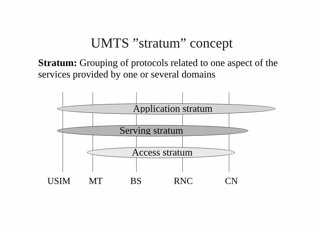
UMTS ”stratum” conceptStratum: Grouping of protocols related to one aspect of theservices provided by one or several domains
USIM MT BS RNC CN
Access stratum
Serving stratum
Application stratum

UMTS bearer service architecture
TE MT UTRAN CN Iuedge node
TECNgateway
End-to-end service
UMTS bearer service
Radio access bearer service CN b.s.
Local b.s. Ext. b.s.
Radio b.s. Iu b.s. Backbone

What is the bearer concept?
Bearer: a bearer capability of defined capacity, delay and biterror rate, etc. (as defined in the 3GPP specs)
Bearer is a flexible concept designating a kind of ”bit pipe”
• at a certain network level• between certain network entities• with certain QoS attributes and capacity
UMTS QoS Classes• conversational, streaming, interactive, background
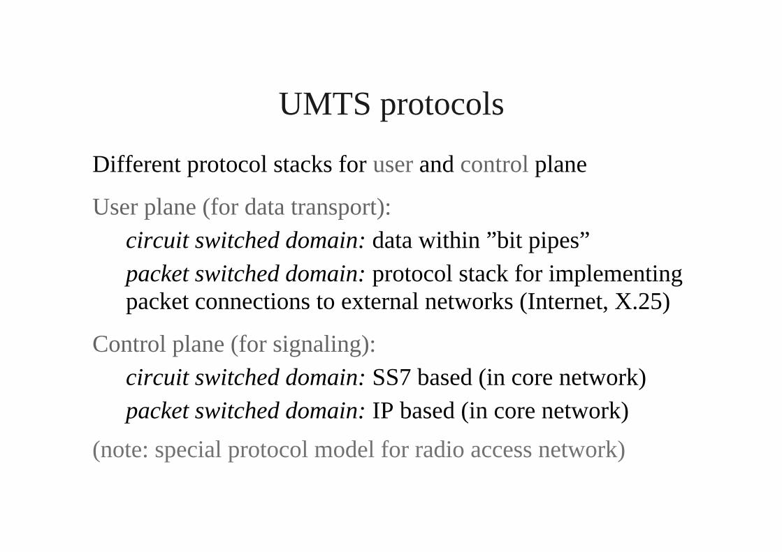
UMTS protocols
Different protocol stacks for user and control plane
User plane (for data transport):circuit switched domain: data within ”bit pipes”packet switched domain: protocol stack for implementingpacket connections to external networks (Internet, X.25)
Control plane (for signaling):circuit switched domain: SS7 based (in core network)packet switched domain: IP based (in core network)
(note: special protocol model for radio access network)

User plane protocol stacks (PS domain)
PDCP
RLC
GTP
TCP
IP
GTP
TCP
IP
IP/X.25 IP/X.25
GTP
TCP
PDCP
RLC
MAC
Phys.
MAC
Phys.
AAL5
ATM
Phys.
AAL5
ATM
Phys.
IP
L2
L1
GTP
TCP
IP
L2
L1
UE UTRAN SGSN GGSN
Uu Iu Gn

Uu interface protocols
L3
L2
L1 PHY
MAC
RLC
RRC
Signallingradio bearers
PDCP BMC
User planeradio bearers
e.g. MM, CMtransparent to UTRAN
Logical channels
Transport channels
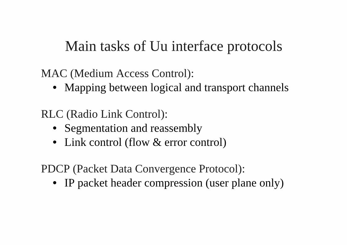
Main tasks of Uu interface protocols
MAC (Medium Access Control):• Mapping between logical and transport channels
RLC (Radio Link Control):• Segmentation and reassembly• Link control (flow & error control)
PDCP (Packet Data Convergence Protocol):• IP packet header compression (user plane only)

RRC protocol
Over the Uu (air) interface, Radio Resource Control (RRC)messages carry all the relevant information required forsetting up, modifying, and releasing links (at lower layers)between the UE and UTRAN. RRC also participates in thecoordination of other Radio Resource Management (RRM)operations, such as measurements and handovers.
In addition, RRC messages may carry in their payload higherlayer signalling information (MM = Mobility Mangement,CM = Connection Management, SM = Session Management)that is not related to the air interface or UTRAN.

General protocol model for UTRAN
RadioNetwork
Layer
TransportNetwork
Layer
Control Plane User Plane
Transport Netw.Control Plane
Applicationprotocol
DataStream(s)
SignallingBearer(s)
ALCAP(s)
DataBearer(s)
Transport Netw.User Plane
Transport Netw.User Plane
SignallingBearer(s)
Physical Layer
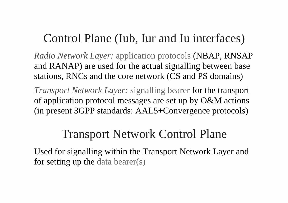
Control Plane (Iub, Iur and Iu interfaces)Radio Network Layer: application protocols (NBAP, RNSAPand RANAP) are used for the actual signalling between basestations, RNCs and the core network (CS and PS domains)
Transport Network Layer: signalling bearer for the transportof application protocol messages are set up by O&M actions(in present 3GPP standards: AAL5+Convergence protocols)
Transport Network Control PlaneUsed for signalling within the Transport Network Layer andfor setting up the data bearer(s)

User Plane (Iub, Iur and Iu interfaces)
The User Plane is used for transport of
• user information (circuit switched speech, Internetpackets)
• control information packed into various transportchannels and sent transparently over radio links
User data streams are carried by data bearers (using AAL2)and may utilize so-called frame protocols (FP) for framing,error control and flow control at the Iub and Iur interfaces

Example (Iub interface)
RadioNetwork
Layer
TransportNetwork
Layer
Control Plane User Plane
Transport Netw.Control Plane
NBAP
Q.2630.1
AAL2
Transport Netw.User Plane
Transport Netw.User Plane
CP
AAL5+CPAAL5
ATM
Physical Layer
Transport channels withapplied Frame Protocols

Application protocols in UTRAN
Iu interface (between RNC and core network)• RANAP (Radio Access Network Application Part)
- Radio Access Bearer (RAB) management- SRNS Relocation- Transfer of higher-level signalling messages
Iur interface (between Serving RNC and Drift RNC)• RNSAP (Radio Network Subsystem Application Part)
- Link management for inter-RNC soft handover
Iub interface (between RNC and base station)• NBAP (Node B Application Part)

Serving RNC and Drift RNC in UTRAN
Corenetwork
Iu
Iur
Iub
Iub
DRNC
SRNC
Soft handover between base stations belonging to different RNCs
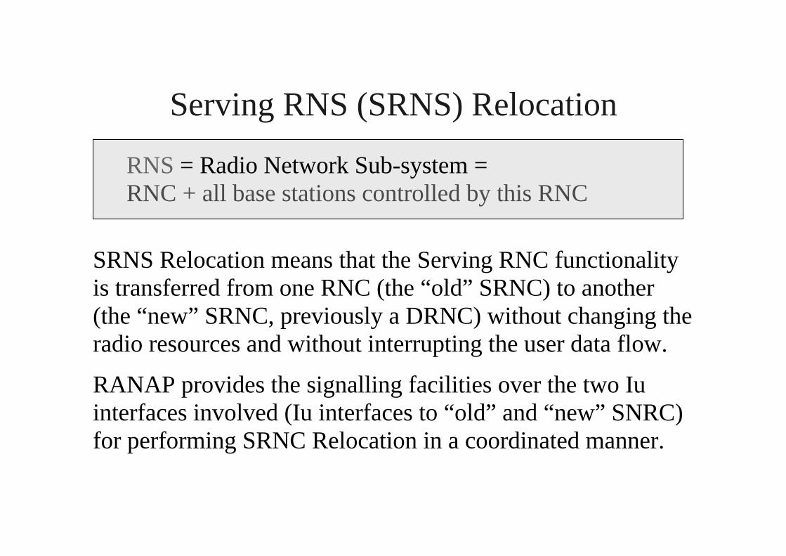
Serving RNS (SRNS) Relocation
RNS = Radio Network Sub-system =RNC + all base stations controlled by this RNC
SRNS Relocation means that the Serving RNC functionalityis transferred from one RNC (the “old” SRNC) to another(the “new” SRNC, previously a DRNC) without changing theradio resources and without interrupting the user data flow.
RANAP provides the signalling facilities over the two Iuinterfaces involved (Iu interfaces to “old” and “new” SNRC)for performing SRNC Relocation in a coordinated manner.

Radio Access Bearer (RAB) establishment
Core networkRNC
RAB assignment request
RAB assignment complete
RAB is configured to be usedover existing Radio Link(s)
(RANAP signaling)

Signalling between UE and Core network
NAS signalling messages (NAS = non access stratum = “notrelated to UTRAN”) are sent transparently through UTRANin the payload of RRC and RANAP protocol messages
UEBase
station RNCMSC
orSGSN
RRC RANAP
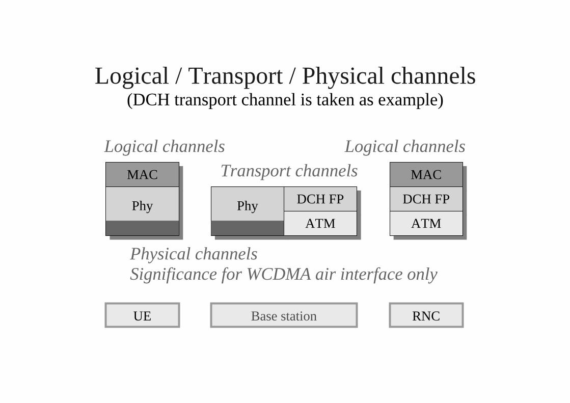
Logical / Transport / Physical channels(DCH transport channel is taken as example)
MAC
DCH FPPhy DCH FP
UE Base station RNC
ATM
MAC
ATMPhy
Logical channels
Physical channelsSignificance for WCDMA air interface only
Transport channels
Logical channels

Logical channels Ø Transport channels
CCCH DCCH
PCH DCHDSCHFACHBCHDCHCPCHRACH
DCCHCTCHCCCHBCCHPCCH
Uplink Downlink
DTCH DTCHLogical channels
Transport channels

Transport channels Ø Physical channels
PCH DCHDSCHFACH BCH
DCH
CPCHRACH
PRACH PCPCH SCCPCH PCCPCH
PDSCH
DPDCH
DPCCH
SCH CPICH
AICH
PICH
CSICH Physical channels
Transport channels
DPCH

Physical channels in WCDMA
Bit sequences in different physical channels are modulatedusing different spreading codes, which are code multiplexed
spreading code = channelization code [ scrambling code
Downlink channels: conventional QPSK modulationDPCH = Dedicated physical channel
Uplink channels: Dual-channel QPSK moduationDPDCH = Dedicated physical data channelDPCCH = Dedicated physical control channel
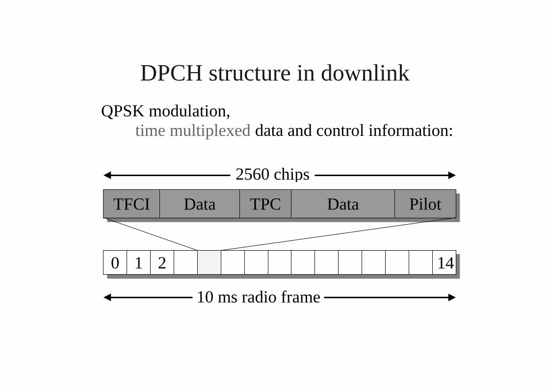
DPCH structure in downlink
QPSK modulation,time multiplexed data and control information:
TFCI Data TPC Data
10 ms radio frame
0 1 2 14
2560 chips
Pilot

DPDCH / DPCCH structure in uplinkDual-channel QPSK modulation:
Data
Pilot TFCI FBI TPC
DPDCH(I-signal)
DPCCH(Q-signal)
10 ms radio frame (38400 chips)
0 1 2 14
2560 chips
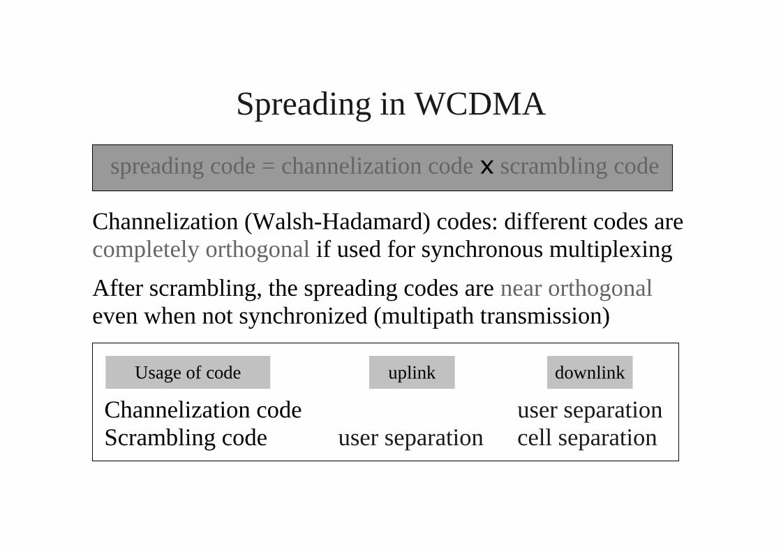
Spreading in WCDMA
spreading code = channelization code [ scrambling code
Channelization (Walsh-Hadamard) codes: different codes arecompletely orthogonal if used for synchronous multiplexing
After scrambling, the spreading codes are near orthogonaleven when not synchronized (multipath transmission)
Channelization code user separation Scrambling code user separation cell separation
uplink downlinkUsage of code
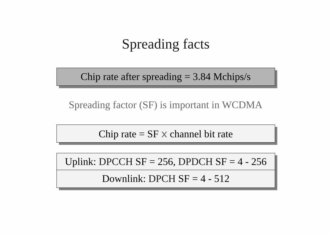
Spreading facts
Spreading factor (SF) is important in WCDMA
Chip rate = SF [ channel bit rate
Chip rate after spreading = 3.84 Mchips/s
Uplink: DPCCH SF = 256, DPDCH SF = 4 - 256
Downlink: DPCH SF = 4 - 512
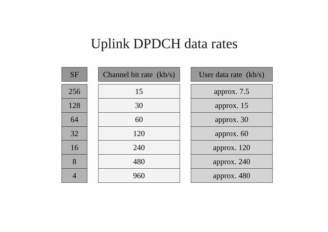
Uplink DPDCH data rates
256
128
64
32
16
8
4
SF Channel bit rate (kb/s) User data rate (kb/s)
15
30
60
120
240
480
approx. 7.5
approx. 15
approx. 30
approx. 60
approx. 120
approx. 240
960 approx. 480
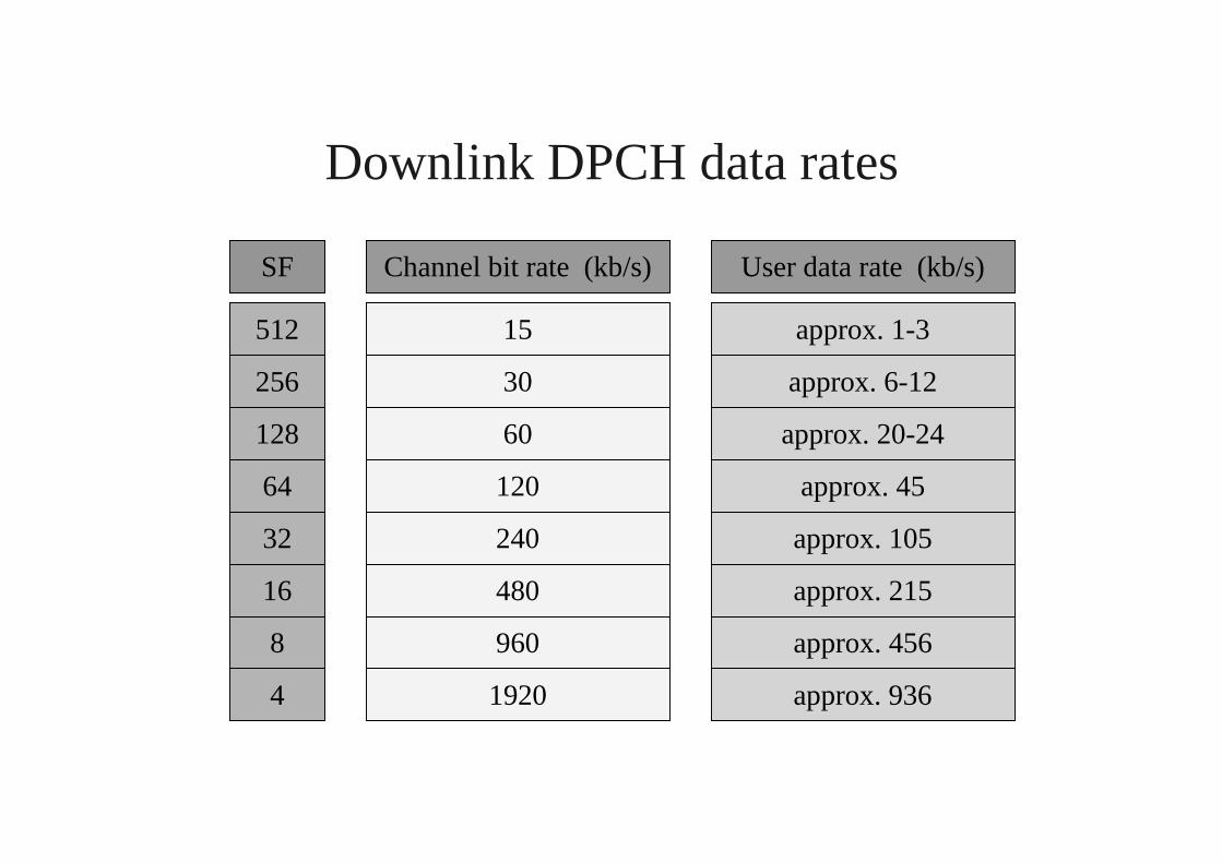
Downlink DPCH data rates
256
128
64
32
16
8
4
SF Channel bit rate (kb/s) User data rate (kb/s)
15
30
60
120
240
480
approx. 1-3
approx. 6-12
approx. 20-24
approx. 45
approx. 105
approx. 215
960 approx. 456
512
1920 approx. 936
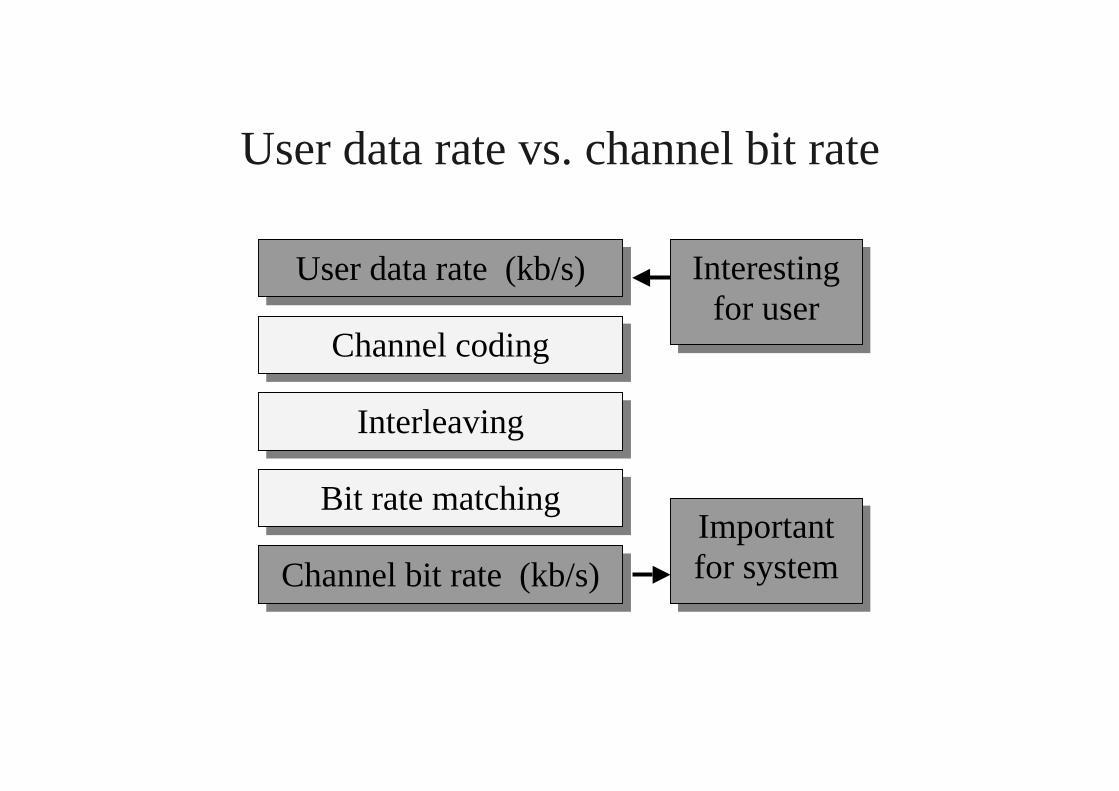
User data rate vs. channel bit rate
Channel bit rate (kb/s)
User data rate (kb/s)
Channel coding
Interleaving
Bit rate matching
Interestingfor user
Importantfor system