tensile properties of pleated synthetic rope - gpo publications nbsir86-337586-3375
TRANSCRIPT

NBS
PUBLICATIONS
NBSIR 86-3375
S. G. Fattal
U.S. DEPARTMENT OF COMMERCENational Bureau of Standards
Center for Building Technology
Structures Division
Gaithersburg, MD 20899
April 1986
Issued September 1986
86-3375
1986
i Proving Ground

NBS
RESEARCH
INFORMATION
CENTER
NBSIR 86-3375
fj f*f r\s*\
TENSILE PROPERTIES OF PLEATED
SYNTHETIC ROPE
S. G. Fattal
U.S. DEPARTMENT OF COMMERCENational Bureau of Standards
Center for Building Technology
Structures Division
Gaithersburg, MD 20899
April 1986
Issued September 1986
Prepared for:
U.S. ArmyAberdeen Proving Ground
U.S. DEPARTMENT OF COMMERCE, Malcolm Baldrige, Secretary
NATIONAL BUREAU OF STANDARDS. Ernest Ambler. Director


ABSTRACT
Pleated nylon ropes of two sizes and approximately the samelength were tensioned to rupture in a universal testing machine.Several of the ropes were tested at room temperature. The otherswere subjected to specified high and low temperatures beforetesting. Deformation measurements of all the specimens wererecorded while testing was in progress. The results were used toevaluate the breaking strength, ultimate elongation, and load-de-formation properties, and to develop criteria for possibleapplication in the recovery of mired vehicles.
Key words: breaking strength? load-deformation? nylon rope?pleated rope? pulse loads? specified strength?stiffness? synthesis? ultimate elongation.
iii

PAGE
CONTENTS
ABSTRACT Ill
1. INTRODUCTION 1
2. DESCRIPTION OF TESTS 1
3. TEST RESULTS 4
3.1 Strength and Elongation 4
3.2 Load-Deformation Behavior 6
3.3 Failure Modes 7
4. INTERPRETAION 8
4.1 Breaking Strength 8
4.2 Stiffness Properties 9
4.3 Synthesis 11
5. SUMMARY AND CONCLUSIONS 14
6. RECOMMENDATIONS 16
7. ACKNOWLEDGEMENTS 17
8. REFERENCES 17
iv
LIST OF TABLES
Page
Table 3.1 Strength and Maximum Elongation 5
Table 4.1 Stiffness Properties of Pleated Ropein Tension 12
v
LIST OF FIGURES
Page
Figure 2.1 Drawing of the 12,000,000 lbfcapacity universal testing machine 18
Figure 2.2 Special fixtures for attachment of ropeto built-in clevises 19
Figure 3.1 Load-deformation curves of specimens1, 3 and 5 20
Figure 3.2 Load-deformation curves of specimens2, 6, 7 and 8 21
Figure 3.3 Load-deformation curves of specimens9, 10 and 11 22
Figure 3.4 Loan-deformation curves of specimens12, 13 and 14 23
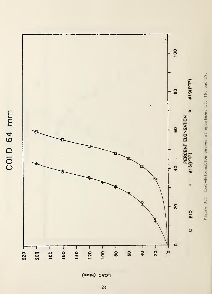
Figure 3.5 Load-deformation curves of specimens15, 16, and 19 24
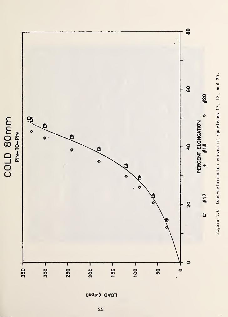
Figure 3.6 Load-deformation curves of specimens17, 18 and 20 25
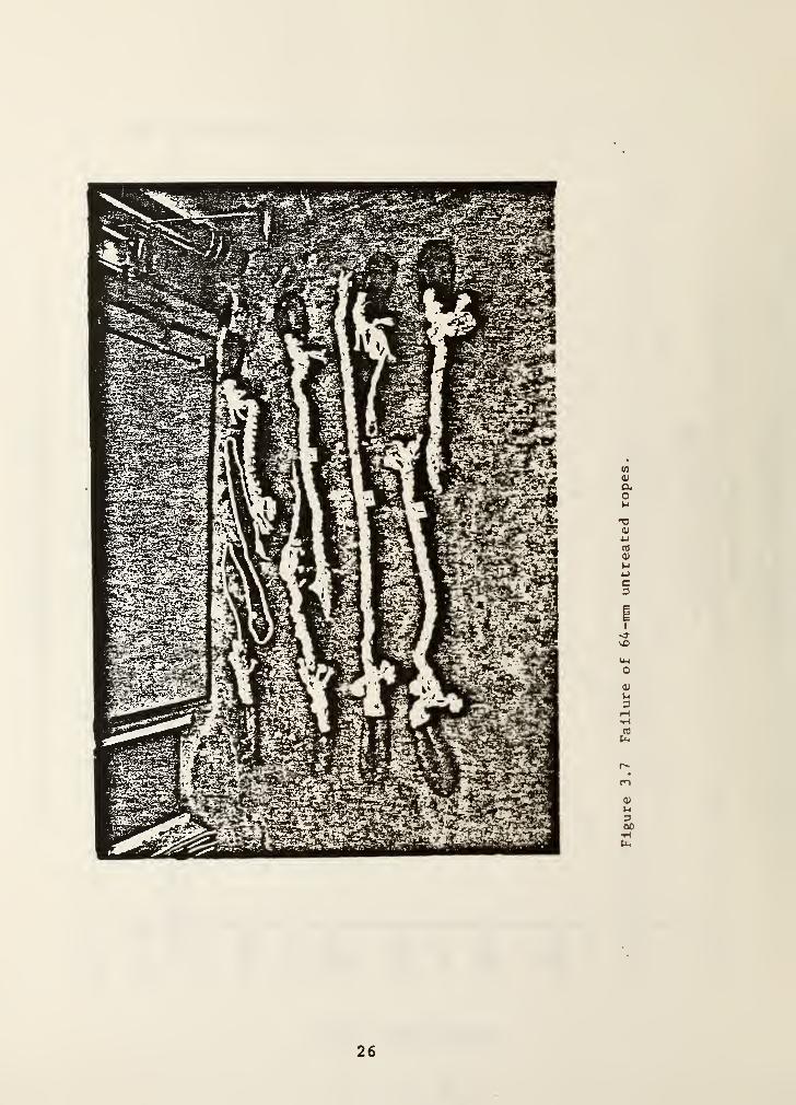
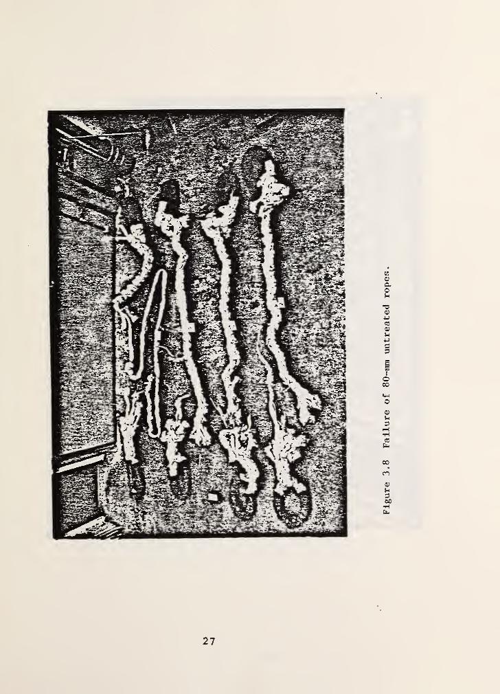
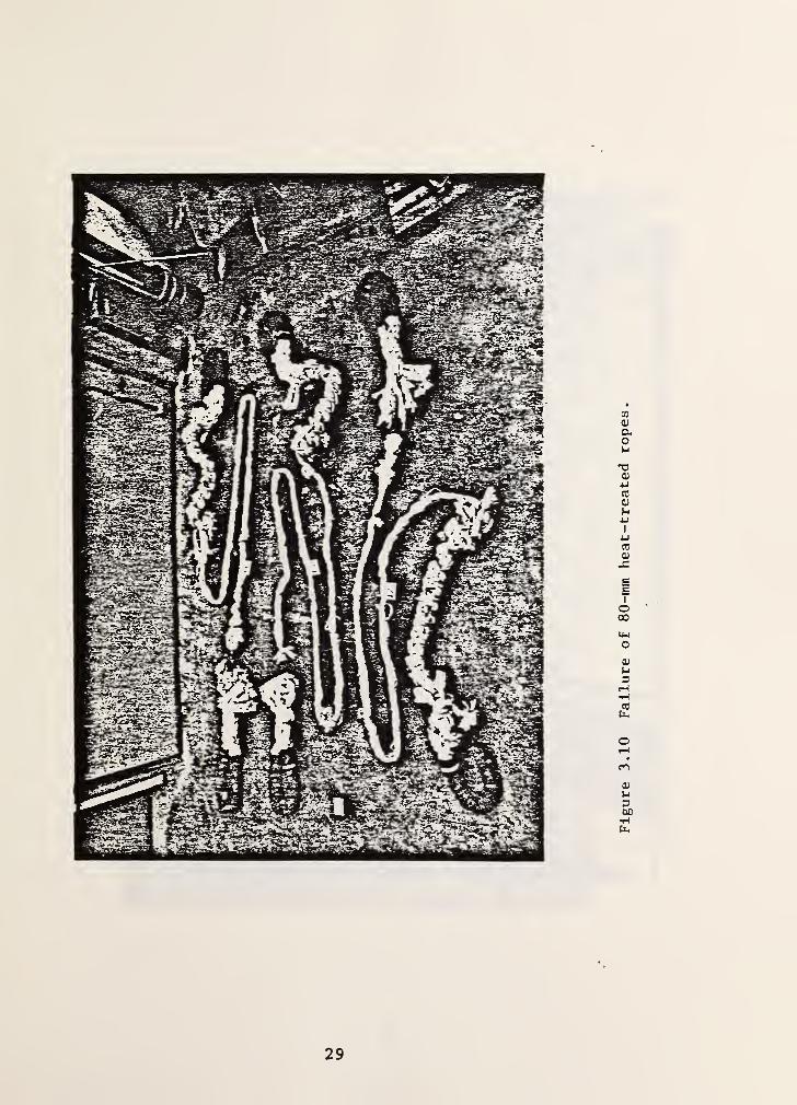
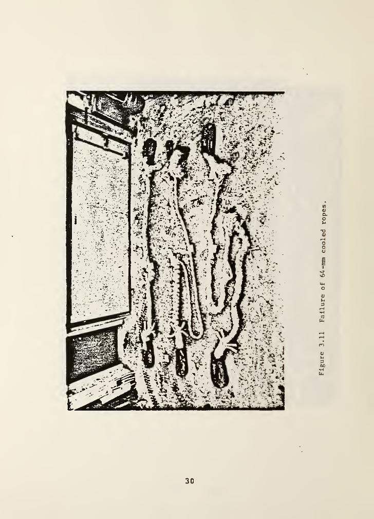
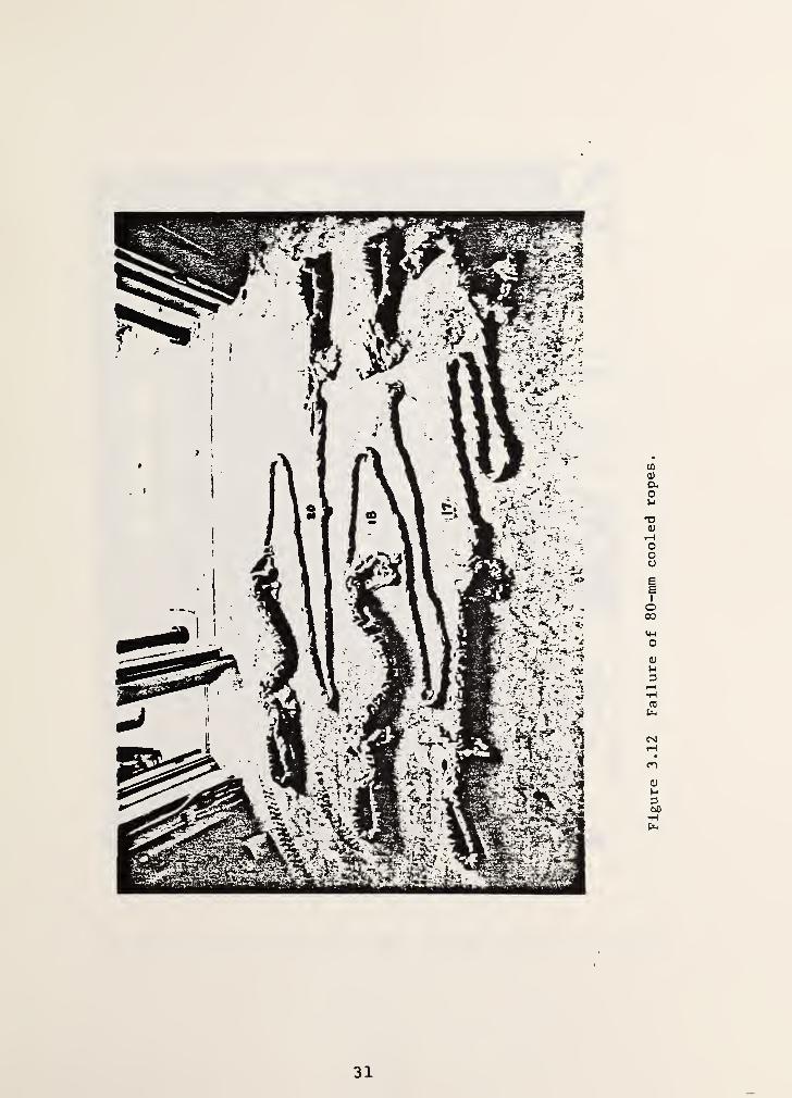
Figure 3.7 Failure of 6 4-mm untreated ropes 26Figure 3.8 Failure of 80-mm untreated ropes 27Figure 3.9 Failure of 64-mm heat-treated ropes 28Figure 3.10 Failure of 80-mm heat-treated ropes 29Figure 3.11 Failure of 64-mm cooled ropes 30Figure 3.12 Failure of 80-mm cooled ropes 31Figure 3.13 General view of 12M lbf universal
testing facility 32Figure 3.14 Specimen #17 being removed from
cooling box 33Figure 3.15 Specimen #17 being installed in the
lower clevis 34Figure 3.16 Specimen #17 under load 35Figure 3.17 Specimen #17 after rupture 36

1. INTRODUCTION
Twenty pleated nylon ropes were tested in tension to determinebreaking strength and load-deformation properties. The ropeswere about 16-ft (5-m) long, center to center of eyes, and wereof two nominal sizes. Some of the ropes were tested under a
constant ambient temperature. Others were heated for a specifiedperiod then tested at ambient, or, were cooled and tested cold.
Synthetic fiber ropes are used in a variety of applications suchas mooring, towing and lifting. The type of rope tested isintended for use by the U.S. Army to recover military tracked oruntracked vehicles stranded in mire, a ditch, etc. The recoveryis accomplished by transferring the kinetic energy of a movingvehicle (the recovery vehicle) through the rope to the miredvehicle as the moving vehicle is brought to a stop by the rope.Full recovery may require several trials. Starting from rest,with a specified slack in the rope, the recovery vehicle attainsa certain velocity before the rope becomes taut and exerts a"shock" load upon the stranded vehicle. The process is repeateduntil the stranded vehicle is recovered.
The tensile tests conducted at the National Bureau of Standards(NBS) is part of a testing program undertaken by the U.S. Army todetermine the suitability of eight-strand pleated nylon rope forkinetic energy recovery applications. Actual use under variablefield conditions is predicated on the resolution of certain keyquestions such as, definition of safe working loads (to preventpremature rupture pf the rope or its attachments) , energy absorp-tion capacity, progressive degradation due to repetitive use, anddegradation as a result of extreme temperature and moistureconditions, or as a result of accumulation of field debris withinthe fibers.
The NBS tests provide data on the strength, stiffness and energyabsorption capacity of pr eviously-untensioned ropes undermonotonic, quasi-static tensile loading to rupture. Theinformation is needed to assist the U.S. Army in the design ofselective field tests and subsequent upgrading of their productcompliance requirements. The ropes were supplied by Marlow RopesLtd. 1
2. DESCRIPTION OF TESTS
The tests were conducted using the NBS large scale testingfacility [1] . The universal testing machine has a rated capacity
1 The manufacturer's or supplier's name is mentioned forproduct identification purposes only, and does notconstitute endorsement of the product.
1

of 6000 kips (26,700 kN) in tension and twice as much incompression. It is equipped with a stationary (locked) tensioncrosshead at the top and a movable (sensitive) crosshead belowthat, as shown in figure 2.1. In tension tests the specimen ismounted between the two crossheads by means of. clevises.Displacement-controlled loading is accomplished by lowering thesensitive head which can be actuated either hydraulically ormechanically.
The existing clevises were equipped with 16-in (406-mm) pinswhich were too large to accommodate the eyes of the ropes. Totest the ropes, special fixtures were fabricated consisting of a6-in (152-mm) diameter by 12-in (305-mm) long pin, a pair of10-in (254-mm) O.D. by 2-in(51-mm) thick by 7-in (178-mm) longsteel tubing, and a pair of 16-in (406-mm) O.D. by 3-in (76-mm)thick by 8-in (203-mm) long steel tubing for each clevis. Thespecial fixtures were designed to keep bearing, shear andflexural stresses of the pin within the allowable limits underthe maximum anticipated breaking load of the rope. A sketch ofthe attachments is shown in figure 2.2.
Except where noted otherwise, the tests were performed inaccordance with Test Method 6015 of Federal Standard 191A [2] .
The standard states that the pins shall be of sufficient size andheld in a manner to assure breaking of the specimen in the freelength. All specimens failed in the free length.
The Standard calls for a measuring device graduated in 1/8-in(3.21-mm) increments. During the tests the displacement of thegage marks were monitored at discrete load intervals by twotheodolites. The resolution of the theodolites was within thespecified tolerance by several orders of magnitude. The theodo-lites were aimed at two bull's eyes flanking the center of therope and about 30-in (760-mm) apart as called for in theStandard. The initial gage length was recorded after loading thespecimen to one percent of its specified breaking load inaccordance with the Standard. The distance center-to-center ofpins was measured at one percent of specified breaking load andat actual breaking load.
To examine extreme temperature effects the ropes were conditionedprior to testing as follows.
Four specimens of each size (64 and 80 mm; 2.52 and 3.15 in) weretested at 72°F (22°C) , which was the constant ambient temperatureof the laboratory. The Standard calls for triplicate tests ofeach size. The additional specimens of each size were initiallytested as trial runs to validate the test setup. As both thesetests turned out to be successful, their results wereconsolidated with the corresponding triplicate tests at ambienttemperature.
2
Three specimens of each size were kept for five days in athermostatically-controlled heating chamber at 165°F (74°C) .
They were then cooled to ambient temperature for one or two daysbefore testing. The temperature of the specimens was monitoredby thermocouples during the cooling process to assure thatambient temperature is attained before testing.
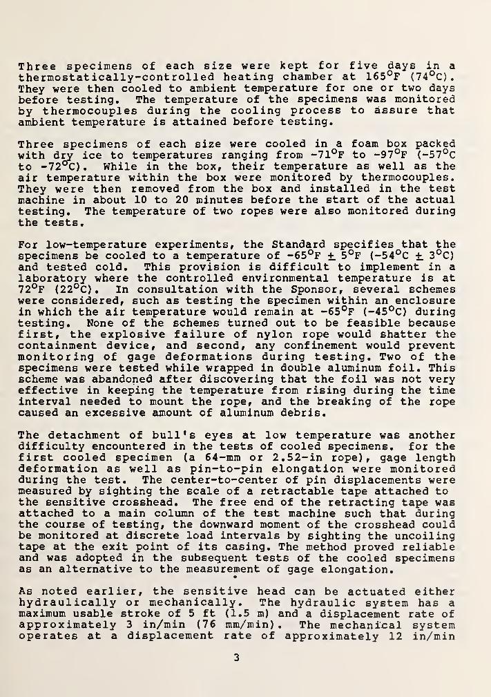
Three specimens of each size were cooled in a foam box packedwith dry ice to temperatures ranging from -71°F to -97°F (-57°Cto -72°C) . While in the box, their temperature as well as theair temperature within the box were monitored by thermocouples.They were then removed from the box and installed in the testmachine in about 10 to 20 minutes before the start of the actualtesting. The temperature of two ropes were also monitored duringthe tests.
For low-temperature experiments, the Standard specifies that thespecimens be cooled to a temperature of -65°F + 5°F (-54°C + 3°C)and tested cold. This provision is difficult to implement in alaboratory where the controlled environmental temperature is at72°F (22°C) . In consultation with the Sponsor, several schemeswere considered, such as testing the specimen within an enclosurein which the air temperature would remain at -65°F (-45°C) duringtesting. None of the schemes turned out to be feasible becausefirst, the explosive failure of nylon rope would shatter thecontainment device, and second, any confinement would preventmonitoring of gage deformations during testing. Two of thespecimens were tested while wrapped in double aluminum foil. Thisscheme was abandoned after discovering that the foil was not veryeffective in keeping the temperature from rising during the timeinterval needed to mount the rope, and the breaking of the ropecaused an excessive amount of aluminum debris.
The detachment of bull's eyes at low temperature was anotherdifficulty encountered in the tests of cooled specimens, for thefirst cooled specimen (a 64-mm or 2.52-in rope), gage lengthdeformation as well as pin-to-pin elongation were monitoredduring the test. The center-to-center of pin displacements weremeasured by sighting the scale of a retractable tape attached tothe sensitive crosshead. The free end of the retracting tape wasattached to a main column of the test machine such that duringthe course of testing, the downward moment of the crosshead couldbe monitored at discrete load intervals by sighting the uncoilingtape at the exit point of its casing. The method proved reliableand was adopted in the subsequent tests of the cooled specimensas an alternative to the measurement of gage elongation.
•
As noted earlier, the sensitive head can be actuated eitherhydraulically or mechanically. The hydraulic system has amaximum usable stroke of 5 ft (1.5 m) and a displacement rate ofapproximately 3 in/min (76 mm/min) . The mechanical systemoperates at a displacement rate of approximately 12 in/min
3

(305min/min) • Its maximum available stroke depends on the initiallength of the specimen. The maximum available distance center tocenter of clevis pins is 45 ft (13,7m). This is more than the30-ft (9-m) estimated length of rope at breaking load.
The nylon ropes consist of eight strands, twisted clockwise andplaited in pairs. In the 80-mm rope each strand consists of 56sets of yarns twisted counter-clockwise. Each set consists ofthree yarns twisted clockwise. Each yarn consists of nylonfilaments. In the 64-mra rope, each strand consists of 44 sets ofyarns twisted counter-clockwise. Each set consists of four yarnstwisted clockwise. The number of filaments in a yarn is lessthan used to prepare the yarns for the 80-mm rope. Thus, toobtain a certain specified size of rope the number of yarns in astrand and the number of filaments in a yarn are altered.
Plaiting introduces a repetitive pattern or a "pitch" in therope. Since plaiting does not introduce a constant twist, theorientation of the filaments with respect to the axis of the ropechanges continuously within a pitch. The manufacturer'sspecified breaking strength is 72000 kilos (158.7 kips) for the64-mm rope, and 110,000 kilos (242.5 kips) for the 80-mm rope.
In the initial tests (specimens 1 through 10), the ropes wereloaded mechanically up to about 50 percent of breaking load. Themachine was then switched to the slower hydraulic system for theremainder of the test. Specimens 11 through 20 were loadedmechanically throughout the entire loading range to examine anyeffects that might occur as a result of the faster loading rate.The hydraulic system could not be used exclusively because thetotal elongation at breaking load would have exceeded theavailable stroke.
3. TEST RESULTS
3.1 Strength and Elongation
Table 3.1 shows the breaking strength and the correspondingmaximum elongation of the individual ropes. For specimens 1
through 15, the elongation of the gage length as well as thelength center-to-center of the 6-in (152-mm) diameter clevis pins(pin-to-pin or PTP length, in brief) were measured. Actual gagelengths and PTP lengths under one percent specified breaking loadare indicated in the table. Except as noted in the table, thepercent elongations of gage and PTP lengths were calculated fromthe total elongation measured at breaking load. Where the lastmeasurement was taken at a load less than the breaking strength,that load has been specified in a footnote to the table. For
specimens 16 through 20 only PTP length elongations weremeasured. Where a measurement was lost due to any cause,attention is drawn by an appropriate footnote to the table.
4
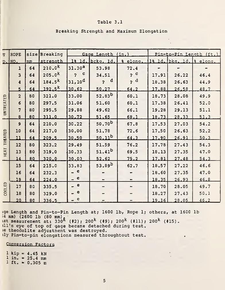
Table 3.1
Breaking Strength and Maximum Elongation
T ROPE size Breaking Gage Length in.
)
+->ic•H ,o-Pin Length (ft .
)
P, NO. mm st renath 1% Id. brkg. Id. % elong. 1% Id. bkg. Id. % elono.
1 64 210.
0
k 31.30 a 53.98 72.4 - -
3 64 205.
0
k ? c 34.51 ? c 17.91 26.22 46.4
4 64 184.
5
k 31,10 d ? d?
d 18.38 26.63 44.9
5 64 192.
5
k 30.62 50.27 64.2 17.88 26.58 48.7
oLU
2 80 321.0 33.00 52 . 83 b 60.1 18.73 28.08 49.9l—<UJ 6 80 297.5 31.06 51.60 60.1 17.38 26.41 52.0q:t—2 7 80 295.5 29.88 49.62 66.1 19.28 29.13 51.1=5
8 §0 311.0 30.72 51.65 68.1 18.73 28.33 51.3
9 64 210.0 30.22 50 ,70 b 67.8 17.53 27.03 54.2
QLU 10 64 217.0 30.00 51.78 72.6 17.50 26.63 52.2h-< 11 64 209.5 30.50 50.11b 64.3 17.90 26.91 50.3oc
12 80 323.2 29.49 51.59 76.2 17.78 27.43 54.3
<LU 13 80 319.0 30.33 51. 41b 69.5 18.13 27.35 47.0
14 §Q 320.0 30.03 52.62 75.2 17.81 27.48 54.3
15 64 215.0 33.83 53 . 89b 62.7 18.57 27.22 46.6
16 64 232.3 _ e - - 18.60 27.35 47.0
19 $4 224.0 _ e — — 18.35 26.93 46.8QLU_J 17 80 335.5 _ e - - 18.70 28.05 49.7OOo 18 80 329.0 _ e - - 18.27 27.43 50.1
-.20 —8.Q. 336.5 _ e - - 19.16 -2$iP5L- 46.2
ige Length and Pin-to-Pin Length at; 1600 lb. Rope 1; others, at 1600 lb>4 mm) (2600 lb (80 mm)-ist measurement at: 330 k (#2); 200 k (#9); 200 k (#11); 200 k (#15).ill's eye of top of gage became detached during test.ie theodolite adjustment was destroyed,ily Pin-to-pin elongations measured throughtout test.
Conversion Factors
1 kip = 4.45 kN1 in. = 25.4 mm1 ft. = 0.305 m
5

3.2 Load-Deformation Behavior
Load-deformation measurements were taken at discrete loadintervals throughout the entire loading range. The deformationswere gage length elongations for specimens 1 through 15, and PTPlength elongations for specimens 16 through 20. This informationis presented as load versus percent elongation plots of theindividual ropes in figures 3.1 through 3.6. Replicate plots ofa given size rope and specified temperature are shown on the samefigure. The average curve of the replicate tests is shown as asolid line. The average percent elongation at 75 percent ofspecified breaking load is also shown. Other comments specificto these curves follow.
Among specimens 1,3, 4, 5 (64-mm ropes tested at ambienttemperature) the load-deformation plots for specimens 1 and 5 arethe only ones available (see footnotes table 3.1). These are infairly close agreement as seen in figure 3.1. The informationfor specimen 4 was not meaningful because one of the theodoliteswent out of adjustment after sighting the initial gage lengthreading. In the case of specimen 3, the actual gage length isnot known because one of the bull's eyes became detached afterthe initial gage length reading had been taken. After the bull'seye was lost, however, the theodolite kept tracking an identi-fiable target until rupture. The load-deformation curve forspecimen 3 shown in figure 3.1 is developed by assuming anarbitrary initial gage length. It is seen that if the elonga-tions of specimen 3 were reduced by the ratio of percentelongation of specimens 1 and 5 to percent elongation of specimen3 at breaking load, the load-deformation curve of specimen 3 willnot be appreciably different from those of specimens 1 and 5.
The load deformation curves for specimens 2, 6, 7, 8 (80-mm ropestested at ambient) are in good agreement, with specimen 2 showingslightly greater stiffness than the rest (figure 3.2). The heat-treated specimens of either size (specimens 9-11 and 12-14), alsoshow close agreement in their load-deformation properties(figures 3.3 and 3.4).
Figure 3.6 shows load versus percent PTP length elongation ofspecimens 17,18,20 (80-mm ropes cooled and tested cold). Thetemperature of specimen 17 was -83°F (-64°C) at the time it wasremoved from the cooler. It was tested 40 minutes later.Specimen 18 registered a temperature of -88°F (-67°C) when it wasremoved from the cooler. At the start of testing 23 minuteslater, a thermocouple embedded at the center. of the roperegistered a temperature of -43°F (-42°C) . The temperature wasmonitored during testing which lasted 10 minutes. The lastreading, taken at rupture was 16°F (8°C) . The temperature of
specimen 20 was -103°F (-75°C) when removed from the cooler. Noother temperature readings are available for specimens 17 and 20
because the thermocouples detached during handling of these
6

specimens. According to the diagrams shown in figure 3.6, thesetemperature differences did not have a significant effect onload-deformation properties.
Figure 3.5 shows the plots for specimens 15, 16, 19 (64-mm ropestested cold). When first removed from the cooler, specimens 15,16, and 19 registered temperatures of -70, -74 and -97° (-56, -59and -72°C) , respectively. The temperature of specimen 16 rangedfrom -5°F to 45°F (-21°C to 7°C) during testing. The temper-atures of the other specimens were not monitored. The nearlyidentical curves for specimens 16 and 19 once again demonstratethe insensitivity of load-deformation properties to initialtemperature differences between the replicate specimens. On theother hand, figure 3.5 indicates a major difference between PTPelongations (specimens 16 and 19) and gage elongations (Specimen15). Most of the differences occurs at 10 percent breaking loadat which point the elongation of the gage length is more thantwice that of the PTP length. Beyond that load level, however,all the specimens exhibited similar stiffness properties untilrupture.
3.3 Failure Modes
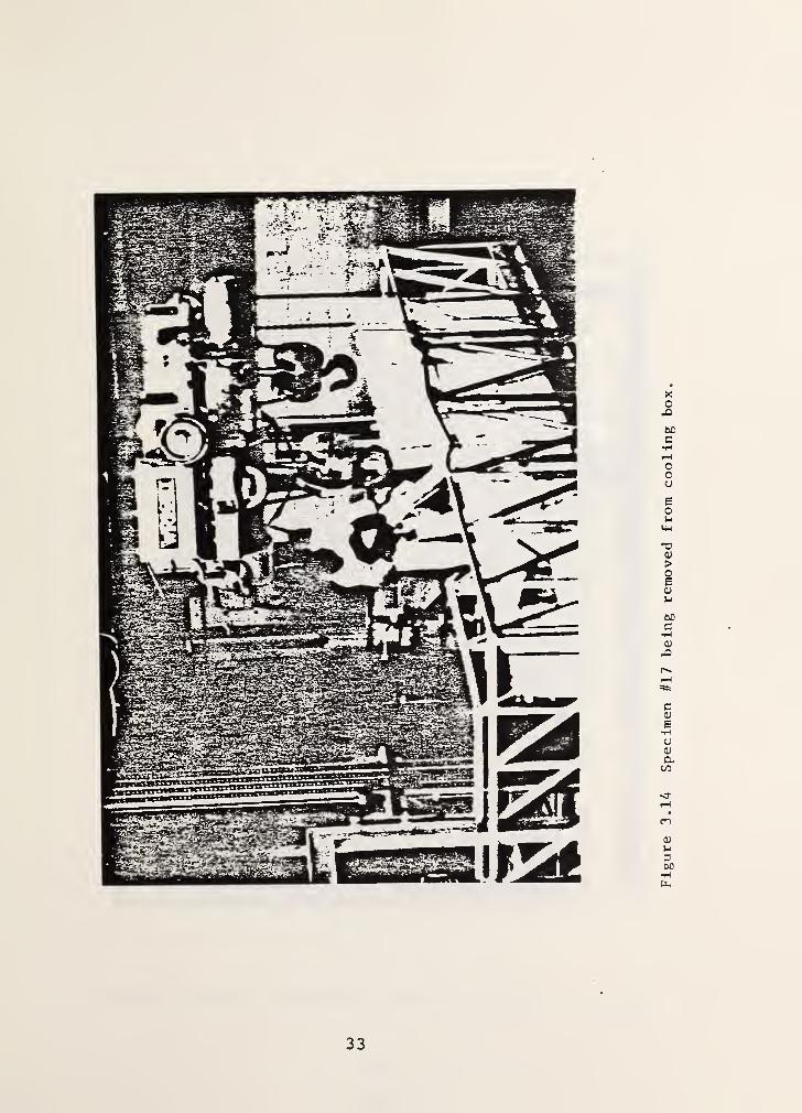
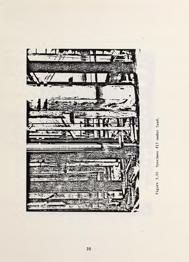
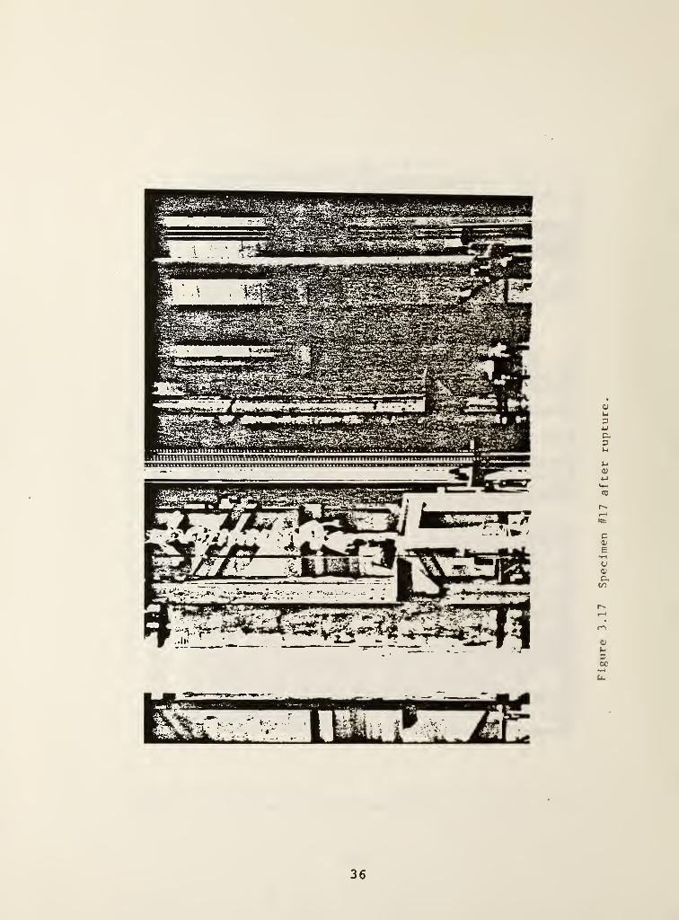
Figures 3.7-3.12 show the specimens after failure. Replicatespecimens are shown in the same figure and are identified bytheir numbers. The top ends of the specimens (as installed inthe test machine) are shown on the left side. Figure 3.13 is ageneral view of the testing facility with a specimen ready fortesting. The movable work platform is at the center of thefigure. Figures 3.14-3.17 show, respectively, specimen 17 beingremoved from the cooling box, being installed in the clevis,under load, and after rupture.
All the specimens broke suddenly and explosively, releasing fiberdebris at the point of rupture. Popping of (intentionally-placed) black yarns within the ropes with increasing frequencyprovided an indication of approaching failure. In all casesrupture occurred in the rope. In some cases the point of rupturewas away from the eyes (nos. 1,4,9,11,19). More frequently,rupture occurred close to or right beyond the eye splice. Noruptures occurred within the eye. Some of the specimens brokecompletely (nos. 1-4,6,7,9,11,19). In the others, a single ordouble-twisted strand remained unbroken.
All the specimens exhibited frictional heat damage to varyingdegrees, as evidenced by the coloring of the yarns from tan todark brown and by their brittle texture. In specimen 1, smokewas detected near the point of rupture before it occurred. Inmost cases scorching was confined to the superficial yarns of thestrands, which had maximum exposure to frictional heat. Oponrupture, the two segments of rope tended to compress axially
7

towards the respective eyes and then solidify in that state, insome cases (specimens 10 and 15) the eye became tightly com-pressed around the pin and had to be sawed off to remove it.Several of the tests were videotaped or photographed on atime-lapse film.
4. INTERPRETATION
4.1 Breaking Strength
The specified breaking strengths of the 64- and 80-mm ropes are158.7 and 242.5 kips, respectively. The actual average breakingstrengths (table 3.1) were 198 and 306.2 kips (881 and 1363 kN)
,
respectively, for the specimens tested at ambient temperature(the coefficient of variation was 0.10 for either size based onfour tests each). The corresponding figures were 212.2 and 320.7kips (944 and 1427 kN) for the heat-treated ropes, and 223.8 and333.7 kips (996 and 1485 kN) for the cooled ropes.
The above information indicates that the specified temperatureconditioning of the ropes had no detrimental effect on breakingstrength. In fact, the cooled specimens developed around 10percent greater strength than the untreated ropes. This may beattributed to the decrease of frictional heat degradation due tothe lower temperature at the start of the test.
In the case of the heat-treated ropes, strength was exceeded byabout 6 percent. The low strength of specimens 4 and 5 couldhave been caused by the abrasion of some of their yarns observedbefore testing. If this possibility is taken into consideration,strength differences between heat-treated and untreated ropesbecomes statistically insignificant. According to the results intable 3.1, the proximity of the point of rupture to the eyesplice (such failures are identified in section 3.3) had noeffect on breaking strength.
As noted in section 2, two different loading rates were used intesting specimens 1 through 10. Attention is drawn to specimens9 through 11 which are replicates. Specimens 9 and 10 wereloaded hydraulically to 100 kips (445 kN) , then mechanically torupture. Specimen 11 was tested mechanically all the way. Inthis instance (table 3.1), the variation in the rate of loadingdoes not show any discernible effect on strength (no unusualscatter compared to the other replicate tests)
.
In summary, ~ heat treatment had no significant effect on breakingstrength while low initial temperature caused the specimens tobreak at slightly higher load than those tested at ambient.There is some visual indication that superficial damage (such ascaused by prior fictional contact with a rough surface) , couldhave an adverse effect on breaking strength. Variation in the
8

rate of loading in the range of 3 to 12 in/min (76 to 305 mm/min)had no significant effect on breaking strength.
4.2 Stiffness Properties
The load-gage length elongation curves shown in figures 3.1through 3.5 exhibit a common trend. Initially, largedeformations occurred under small loads. About two-thirds of theultimate elongation occurred under 10 percent of the actualbreaking load. Most of the stiffness gain occurred between 10and 30 percent of the breaking load. Beyond that level, thestiffness remained fairly constant to rupture.
The low stiffness under small loads may be attributable to theslack in the "weave" of previously-untensioned plaited rope andpossibly, to initial creep effects due to the slow displacementrate used. The consistency in replicate test results suggeststhat at a certain load level (about 30 percent, in this case) therope becomes fully taut and develops a "characteristic"stiffness. Since the maximum rate of loading also occurs at thispoint and beyond, creep effects beyond the 30 percent load rangemay not be significant. This is reinforced by the absence ofkinks in the load-deformation curves in cases where the loadingwas temporarily stopped to allow the theodolite readings to keeppace with the test.
For certain applications, manufacturers suggest that pleated ropebe "stabilized" first by subjecting it to a specified number ofload cycles at a given amplitude. This process minimizeshysteretic effects, stiffens the rope and renders its load-deformation response fairly linear. However, partial recovery ofthe resulting permanent elongation occurs with time.
In a kinetic energy recovery operation, the rope is subjected tothree or four tugs. It is then stored, sometimes for months,before the next use. Between the tugs, the rope folds uponitself when the recovery vehicle backs up towards the miredvehicle before the next attempt. Perhaps because both thesefactors will tend to make a previously tensioned or stabilizedrope slack, the present Standard [2] does not call for priorstabilization as a prerequisite for testing.
There is, however, another factor that needs to be considered.According to field tests conducted at the U.S. Army AberdeenProving Ground (APG) , the 'duration of the initial pulse load of atug is typically in the neighborhood of two seconds (one secondrise time) [3] . This fast rate of loading is greater by severalorders of magnitude than that achieved in the NBS universaltesting machine.
In a recent field test of an 80-mm rope from the same source asthe NBS specimens, but 70-ft (21-m) long, elongations produced by
9
pulse loads of 120 and 165 kips (534 and 760 kN) were in theorder of 10 and 18 percent, respectively. This indicates thatthe soft portion of the response curves obtained from the NBStests may not materialize under a pulse-type load.
Because of its short period, it is possible that a pulse loadwill engage part of the fibers but will not allow full tautnessto occur. The resulting stiffness would then be somewhat lessthan the characteristic stiffness of a fully taut rope obtainedfrom quasi-static tests. If, for instance, a constant stiffnessis assumed for the average response curve (figure 3.2) betweenthe data points at 120* and 240*^ (530 and 1070 kN) (this portionof the curve is virtually linear), the corresponding elongationswould be 8 and 17 percent, respectively. Therefore, on the basisof this limited information, it appears that the characteristicstiffness obtained from quasi-static load tests provides an upperbound estimate on the stiffness obtained from the pulse-typeloads encountered in recovery operations.
The response curves of 64-mm untreated ropes (specimens 1 and 5,fig. 3.1) are not distinguishable from those which wereheat-treated first (specimens 9,10 and 11, fig. 3.3). Atbreaking load, the gage length elongations were likewise in closeagreement, while the PTP elongations of the heat-treated ropeswere, on the average, 12 percent more than those of the untreatedropes. No specific reason can be given for this last difference,except to note that the gage length elongations for specimens 9
and 11 were obtained at a load slightly less than their breakingstrength (footnote b to table 3.1), and also, elongationsmonitored on a longer portion of the rope (PTP length) tend toprovide a better indication of the overall heat effect than thoseobtained from a much shorter segment of rope (the gage length)
.
Similar observations can be made on the responses of 80-mmuntreated and heat-treated specimens. Differences in theresponse curves (figs. 3.2 vs fig. 3.4) as well as gage and PTPelongations at breaking load (table 3.1) are slight or insignifi-cant. Note that heat treatment had almost no effect on thecharacteristic stiffness of either size rope (the slope of theresponse curve between approx. 30 and 90 percent of actualbreaking load)
•
Because of a change in deformation measurements from gage to PTPlength, no direct comparison can be made between the load-deformation responses of untreated and cooled specimens. Theresults for specimen 15 provide a possible link between the two.Attention is drawn to figure 3.5 where the response curves of the64-mm cooled ropes are plotted. Beyond a load of about 40 kips(180 kN) , the curves are virtually identical in slope. In otherwords, if the curve of specimen 15 were shifted to the left itwould closely match these for specimens 16 and 19, which weredeveloped from PTP elongations. The difference in the response
10

curves below 40 kips (180 kN) suggests the presence of a greaterdegree of initial slackness in the gage length portion than inthe rest of the rope. An indication of this trend is provided bythe data in table 3.1 where the PTP elongations of specimens 1
through 14 at breaking load are consistently and significantlylower than the corresponding gage length elongations. Note thatthe gage length and PTP elongations of specimen 15 at breakingload is consistent with those for the 64-mm untreated ropes whileits PTP elongation closely agrees with those of replicatespecimens 16 and 19. These observations lend creditability tothe test results of specimen 15.
Table 4.1 provides estimates of the stiffness properties in thenear-linear range of the response curves. These were calculatedby assuming a linear response between data points at 80 and 160kips (356 and 712 kN) for the 64-mm ropes, and 120 and 240 kips(534 and 1070 kN) for the 80-mm ropes. The load-strain ratio isthe slope of this linear portion divided by 100. The (character-istic) stiffness is the load-strain ratio divided by theappropriate gage or PTP length. The listed properties werecalculated using average response curves of replicate tests.
The data in table 4.1 yields weighted average load-strain ratiosof 956 kips (4254 kN) for the 64-mm ropes, and 1346 kips (5990kN) for the 80-mm ropes. The changes in load-strain ratios dueto heat-treating or cooling the specimens before testing are notsignificant, in light of the inherent scatter in the test resultsand the approximation introduced by the assumption of linearresponse. The trend in the characteristic stiffnesses is thesame. Note that since stiffness is inversely proportional tolength, a stiffness based on the PTP length will be less thanthat based on the gage length by the ratio of their lengths.This explains the low stiffness values of the cooled ropes (table4.1) determined on the basis of the PTP length.
In summary, pleated nylon rope develops a characteristicstiffness within the range of approx. 30 to 90 percent of actualbreaking load. This stiffness appears to be an upper boundestimate of the stiffness under a pulse-type load occurring inenergy recovery applications. This observation is preliminaryand needs further verification by selective field tests.Subjecting the rope to a specified high temperature for aspecified length of time before testing at ambient temperaturedid not alter its mechanical properties under quasi-statictensile loading. Similarly, cooling the specimen to a specifiedtemperature and testing it cold did not have a discernible effecton these properties.
4.3 Synthesis
Several factors will influence the choice of a rope suitable forkinetic energy recovery application. The right combination of
11

Table 4.1
Stiffness Properties of Pleated Rope in Tension
Size andTemperatureConditionina
Load-strainRatiokiDS (kN)
Stiffnessk/ft (kN/m)
64 mmUntreated
875 341
(Specimens1 and 5)
(3894) (463)
64 mmHeat Treated
975 387
(Specimens9.10.11)
(4338) (525)
64 mmCooled
1126 400
(Specimen15)
(5011) (543)
64 mmCooled
1026 56
(Specimens16 & 19)
(4343) (72)
80 mmUntreated
1481 571
(specimens2. 6.7. 8)
(6590) (775)
80 mmHeat Treated
1319 528
(Specimens12.13.14)
(5870) (716)
80 mmCooled
1237 66
(Specimens17.18.20)
(5505) (90)
12
size and length of rope will allow the required amount of energytransfer to recover the mired vehicle, while keeping theamplitude of the pulse load within a safe limit to avoidpremature rupture of either the rope or its attachments and toinhibit frictional heat degradation.
According to the NBS tests, pleated nylon rope develops acharacteristic stiffness in tension under a slow rate ofloading. From the limited information available from field testsat APG, it appears that the characteristic stiffness provides anupper bound estimate of the stiffness occurring under apulse-type loading in a kinetic energy recovery operation. Ifthis observation could be further corroborated by additionalfield tests, the characteristic stiffness can be used as acriterion in the selection of an appropriate length for a givensize rope.
Suppose, for example, the length L of a given size rope isdesired. Assuming linear response, the stiffness k of the ropeis given by
K (4.1)
where P is the tensile force and a is the corresponding elongationin length L. The notation L
Qand kQ designate the length and
stiffness of a specimen of tne same size obtained from tensiletests (for instance, kQ = 571 kips/ft for the 80-mm untreatedrope based on the average PTP length of 18.53 ft, tables 3.1 and4.1)
.
The strain energy Us under load P is then.
U,Pa2 2k 2k.o o
This yields an estimate of the desired length.
L =2koLous
(4.2)
(4.3)
Assuming full energy transfer, the strain energy Os will be equalto the kinetic energy of the recovery vehicle, Uk = mvz/2, wherem is the mass and v is the velocity of the vehicle just before itexerts a pulse load on the rope. Load P will be governed byconsiderations of maximum safe load to avoid failure in the ropeor its connections during recovery, and to minimize frictionalheat degradation in the material.
13

The compliance testing requirements of the present Standard canbe upgraded in certain areas to reflect the findings of the NBStests noted above. For instance, the requirement for recordingelongations at 75 percent of the specified minimum. breakingstrength will not yield meaningful results because the largedeformations occurring under low static loads in a previously-untensioned rope will distort the results significantly. Sincethere is partial evidence that such large deformations do notoccur under pulse loads, it would be more meaningful to require,instead, deformation measurements to be taken at two distinctload levels, expressed as percentages of specified breakingstrength. The selection of the two load levels should be made insuch a manner as to yield reliable information on the charac-teristic stiffness of the rope. For the ropes used in the NBStests, data points at 40 and 80 percent actual breaking load (or50 and 100 percent specified breaking load) provided reasonablygood estimates of the characteristic stiffness.
The definition of a safe working load depends on the strength ofthe rope, the strength of the connections and the load-capacityof the rope within which no permanent damage will occur. The NBStests provide information on the first of these factors. Theaverage breaking strength of the specimens exceeded the specifiedstrength by 25 percent in the case of the untreated ropes of bothsizes (section 4.1). The corresponding coefficient of variationwas around 10 percent. Therefore, the specified strength appearsto be reasonably conservative. In addition, the eyes of the testspecimens had sufficient strength to develop the strength of therope. However, it is not known whether this will also be true ifa different pin size were used.
The Standard should stipulate that the connections should bestrong enough to develop the strength of the rope. This willrequire verification through independent testing of the connec-tions. The last factor, the maximum load that can be applied tothe rope without causing material degradation, can be addressedby extending the scope of testing to include cyclic loadingfollowed by loading to rupture. In such investigations theprincipal test variables would be the amplitude of the cycledload, the number of cycles, and possibly, the time interval atzero load between consecutive cycles.
5. SUMMARY AND CONCLUSIONS
Pleated nylon ropes of two sizes and approximately the samelength were tested in tension to failure in a universal testingmachine. Some of the ropes were tested at the ambienttemperature of the laboratory. To study high and low temperatureeffects, the remaining specimens were subjected to a specifiedtemperature for a specified number of days and tested at the
14

they were cooled to a specifiedambient temperature, or,temperature and tested cold.
The tests and pre-conditioning for temperature effects werecarried out in accordance with the U.S. Army testingspecifications for synthetic rope. The Army intends to use theropes to recover mired military vehicles provided certainconditions are met. The NBS tests were part of a broaderprogram, currently being implemented by the Army, to determinethe suitability of pleated synthetic rope for recoveryapplications. This report documents and interprets the NBS testresults in the light of this intended use. Included are data onbreaking strength, corresponding elongations, and load-defor-mation properties. The following conclusions are drawn based onthe observed behavior of the ropes in tension.
The mean breaking strength of the untreated specimens exceededthe specified strength by 25 percent. The coefficient ofvariation was 0.10 based on four replicate tests of each size.
The mean breaking strengths of heat-treated and cooled specimenswere about 6 and 9 percent above the mean breaking strength ofuntreated rope, respectively. The coefficient of variation basedon triplicate tests varied from 0.03 to 0.09, depending on sizeand type of treatment. The slightly higher strengths compared tountreated rope cannot be given much significance because of smallsample size. However, it is reasonably safe to assume that thespecified temperature treatment will have no detrimental effecton strength.
Similarly, the prescribed high and low temperature treatments hadno significant effect on the load-deformation properties of thespecimens. It is therefore concluded that simulated vehiclerecovery tests in the field need not be concerned with ambienttemperature fluctuations, specially since it is very unlikelythat the extreme temperatures used in the tests will beencountered in the field.
All the specimens exhibited consistent load-deformationproperties. In specimens where gage length elongations weremeasured, about two-thirds of the ultimate elongation occurredwithin 10 percent of breaking load. Between 10 and 30 percent ofbreaking load, the specimens developed full stiffness whichremained nearly constant up to breaking load. In specimens wherepin-to-pin (PTP) length elongations were measured, about one-third of the ultimate elongation occurred under 10 percent ofbreaking load. Otherwise, the response was nearly identical tothose based on gage length elongations. The difference isattributed to differences in the initial slackness of the rope asa whole, versus that present in the gage portion of the rope.
15
According to the test results, a given size rope will develop acharacteristic stiffness when tensioned at a low displacementrate (compared to the high flexibility of the specimen) typicalof a universal testing machine. Good agreement between thecharacteristic stiffnesses obtained from gage and PTP elongationmeasurements of replicate specimens provides a degree ofconfidence that this is a dependable or "stable" property.
On the basis of limited field tests by the U.S. Army, there issome evidence that the characteristic stiffness provides an upperbound estimate on the stiffness that develops under a pulse-typeload occurring in mired vehicle recovery operations. Subject tofurther verification through additional field tests, thecharacteristic stiffness could be used as a key parameter in theselection of an appropriate size and length of rope for use inrecovery applications.
The tests show that elongation measurements at 75 percent of andat breaking load currently required by the Army specificationsare distorted considerably due to the initial slack existing in a
previously-untensioned rope. It would be more useful to takeelongation measurements within the stable portion of load-elongation curves for the purpose of determining thecharacteristic stiffness. According to the test results,elongation measurements at 40 and 80 percent of actual breakingload (or 50 and 100 percent of specified breaking load) shouldyield reasonably accurate estimates of the characteristicstiffness.
6. RECOMMENDATIONS
The tensile tests of pleated nylon rope provided a ceratin amountof basic information on strength and stiffness properties whichwill be useful in upgrading current specifications and indeveloping the scope of supplementary tests. The following aresuggested areas of research.
Selective field tests should be carried out to increase the database on stiffness properties of rope under pulse-type loads. Theresults can be used to better correlate the stiffness obtained bystatic load tests with that expected to occur in recoveryoperations.
One question not addressed by this study is the maximum load therope can be tensioned to without causing strength degradation.This can be achieved by cyclic tests followed by loading torupture. The test variables would be the number of cycles andthe amplitude of load. Another useful product of these testswould be the stabilization of the ropes as a result of cyclicloading. The stiffness of stabilized rope can then be compared
16

and correlated with the characteristic stiffness obtained fromstatic load test.
Frictional damage to surface fibers, debris penetration, and highmoisture content are probable occurrences in the field. Theeffect of these factors on strength, stiffness andenergy-absorption properties of pleated synthetic rope should bestudied through controlled environment tests, or field tests, orpreferably both. These investigations will provide informationwhich can be used to develop criteria for rejection orreplacement
.
7 . ACKNOWLEDGEMENTS
The assistance of the following persons or group is acknowledged.R. Sanders and K. North of the D.S. Army supplied information onthe product and field test data, N. J. Carino developed thecomputer plots in this report, several CBT technicians providedassistance in conducting the tests.
8. REFERENCES
1. Kirstein, Arthur, F., Universal Testing Machine of 12-Million-lbf Capacity at the National Bureau of Standards, NBSSpecial Publication 355, National Bureau of Standards,Washington, D.C., September, 1971.
2. Strength and Elongation, Breaking of Cordage; SplicedSpecimen Method 6015, Federal Standard 191a, July, 1978.
3. Shaieb, Mark, Tensile Loads Applied to the BFV During aKinetic Energy Recovery, Technical Report 4143, OrdinanceDivision (Engineering), FMC Corporation, San Jose,California, July, 1985.
17

T I E PLATE
Figure 2.1 Drawing of 12,000,000 lbf capacity universal testing machine
18

Figure 2.2 Special fixtures for attachment of rope to
built-in clevises.
19
MATERIAL:
AS
TM
A
291-
*.4
,
CLASS

ROOM
TEMPERATURE
(*d|>o oven
20
PERCENT
ELONGATION

ROOM
TEMPERATURE
oCO
<
o o o o O o o om o m o m o in•o »o CM CM •— *—
(sdi>o oven
21

HEATED
64
(*di>o avon
22
PERCENT
ELONGATION
+
#10

HEATED
80
oCO
(sdpt) oven
23
PERCENT
ELONGATION
COLD
64
(cdiJi) QVOI
24
PERCENT
ELONGATION
#16(PTP)
O
#19(PTP)
COLD
80mm
PIN-TO-PIN
(•dpi) ayol
25
PERCENT
ELONGATION
26
Figure
3.7
Failure
of
64-iran
untreated
ropes.
27
Figure
3.8
Failure
of
80-mm
untreated
ropes.

28
heat-treated
ropes.
29
Figure
3.10
Failure
of
80-mm
heat-treated
ropes.
30
Figure
3.11
Failure
of
64-mm
cooled
ropes.
31
Figure
3.12
Failure
of
80-mm
cooled
ropes.

Figure 3.13 General view of 12M lbf universal testing facility.
32
33
Figure
3.14
Specimen
//
17
being
removed
from
cooling
box.

Figure 3.15 Specimen #17 being installed in the lower clevis.
34
35
Figure
3.16
Specimen
//
17
under
load.
36
Figure
3.17
Specimen
fl\7
after
rupture.
NBS-114A (rev. 2 -6>c)
U.S. DEPT. OP COMM.
BIBLIOGRAPHIC DATASHEET (See instructions)
1. PUBLICATION ORREPORT NO.
NBSIR 86-3375
2. Performing Organ. Report No 3. Publication Date
SEPTEMBER 1986
4. TITLE AND SUBTITLE
Tensile Properties of Pleated Synthetic Rope
5. AUTHOR(S)
S. George Fattal
6. PERFORMING ORGANIZATION (If joint or other than NBS, see instructions)
national bureau of standardsDEPARTMENT OF COMMERCEWASHINGTON, D.C. 20234
7. Contract/Grant No.
8 . Type of Report & Period Covered
9. SPONSORING ORGANIZATION NAME AND COMPLETE ADDRESS (Street. City. State, ZIP)
United States Army Aberdeen Proving Ground
10. SUPPLEMENTARY NOTES
| |
Document describes a computer program; SF-185, FIPS Software Summary, is attached.
11. ABSTRACT (A 200-word or less factual summary of most significant information. If document includes a significantbi bliography or literature survey, mention it here)
Pleated nylon ropes of two sizes and approximately the same length were tensionedto rupture in a universal testing machine. Several of the ropes were tested atroom temperature. The others were subjected to. specified high and low temperaturesbefore testing. Deformation measurements of all the specimens were recorded whiletesting was in progress. The results were used to evaluate the breaking strength,ultimate elongation, and loajd-defQrmatidn properties, and to develop criteria forpossible application in the recovery of mired vehicles.
12. KEY WORDS (Six to twelve entries; alphabetical order; capitalize only proper names; and separate key words by semicolon s)
breaking strength; load-deformation; nylon rope; pleated rope; pulse loads;specified strength; stiffness; synthesis; ultimate elongation
13. AVAILABILITY
Unlimited
| |
For Official Distribution. Do Not Release to NTIS
Order From Superintendent of Documents, U.S. Government Printing Office, Washington, D.C.20402.
[V] Order From National Technical Information Service (NTIS). Springfield, VA. 22161
14. NO. OFPRINTED PAGES
43
15. Price
$9.95
USCOMM-OC 8043-P90