techxcal notes - - digital library/67531/metadc54160/m... · · 2017-12-29gle report of length...
TRANSCRIPT

TECHXCAL NOTES -
. XA?IOXAL ADVISORY CCMlITTPE FOB AEROHAUTICS
_..-. _ .-.- .__
.;.z1.. : . . . .:. -
,- - - ..- -. - -.
. . . _. : .--._ --_ -
- .-
PART 1 - DEBIVATIOX 02 FORJrVLAS
By A. Hurrag Schwartz
PAX!! xx - EXPERXMEHTAL lWVESTIGA!F.ILO# OF FOl'lX(Y$AS
By Ret& Bogert
,6tanford Unfversity
. - -._. -. .

N.A.C.A. Technfcal Note Bo. 529
PREFACE
The problem of a precise method of analysis for air- plane jury-strut systems was selected by Mr. A. Murray Schwartz as the subject of his Engineer's thesis at Stanford University. Mr. Schwartz's study resulted in the derivation of suitable theoretical equations and the de- velopment of a system of using them in practical design. He did not have time, however,, to carry out any experi- mental work to prove the validity of his formulas. In the winter of 1933-34 another graduate student at Stanford, Mr. Reid Bogert, made the experimental investigation.of Mr. Schwartz's formulas the subject of his Engineer's the- sis, and obtained data to prove their validity.
Owing to the length of these theses, the N.A.C.A. did not consider it advisable to publish them in full, but - accepted the offer of the writer, under phose'direction the two theses were prepared, to combine them into a sin- gle report of length suitable for publication. The work of the writer has been primarily editorial, the theoret- ical derivations of the first part of the report being that of Schwartz, and the experimental work of the second part that of Bogert. Vhile the theses on whxch the pres- ent report is based were written under the direction of the writer, his supervision was not very close and by far the greater part of the credit belongs to the two students. -
The title of Schwartz's thesis was "Structural Analy- sfs of Airplane Jury Strut Systems". Study of the prob- lem showed that its essential feature was the analysis of a strut with a single elastic support at any specified point between its ends. This is a general problem of which the airplane jury-strut system is only a special ' case. BogerG's thesis was accordingly entitled "Tests on Struts with a Lateral Elastic Support fn the Span". The title of the present paper was chosen to fndicate both the essential problem attacked and its most important appli- cation in aeronautical design.
Alfred S. ITiles.

NATIOEAL ADVISORY COMITTEE FOR AERONAUTICS
TECHtlIC%L HOTE X0. 529 .--- .- -
AWALYSIS OF A STRUT FAITH A SIi$GLE ELASTIC SUPPORT IN
THE SPAN, 9TITH APPLICATIONS.TO THE DESIQN
OF AIRPLAITE JURY-STRUT SYSTEMS
By A. Murray Schwartz and Reid Bogert
PART I
DERIVATIOB OF FORMULAS
By A. M. Schwartz
f. IWTROD-UCFION
The need of a precise analysis of airplane jury-strut systems was suggested by Mr. Richard C. Gazley in an arti- cle entitled'"Late Developments in Airplane Stress Analy- sis Methods and Their Effect on Airplane Structures."* In the paragraphs on the jury strut, he says, "Among design- ers of strut-braced monoplnnee, -there is an increasing tendency to reduce the weightof the external wing bracing by providing the main struts with lateral support at about one third the distance in from tho outer ends. This sup- - port is furnished by a small auxiliary strut, commonly called a jury strut, which 5s attached to the wing spar at its upper end. This type of design is q,uite effective for the purpose intended, but it has introduced some dif- ficult analysis problems.
"The case in w-hich the auxiliary strut and the upper end of the main strut are both pinned at their intersec- tion is fairly simple, and has been successfully analyzed by a number of designers. TLe score common case, however, where the main lift strut is continuous, is greatly com- plicated by a number of factors affecting the force dis- tribution. A precise solution of this problem probably nould result in unwieldy formulas but would enable the im- portance of the various factors to be determined." -I_- --- -- * s .a.e. Journal, Septeiaber 1932.
-_ -I-

2 W.A.C.A. Technical Note No. 629
The problem assumes a difficult as-et because of the simultaneous deflection of both strut and spar, one dependfng upon the other, and because of the secondary stresses and deflections present due to axial load5 in the members. This can easily be illustrated by reference to figure 1, in which the broken line represents the un- stressed structure, and the solid lines an exaggerated view of the members when under load. The elastic curve of the spar is, of course, quite dependent upon the side or air load upon it and the amount of overhang. Since ax- ial compression is the critical load on the lift strut, the airplano is assumed to be in inverted flight. This condition impose5 a "down" side load upon the spar, and consequently the spar and strut are under axial tension, and compression, respectivel.y.,. If a jury strut is con- II
netted to the spar at point <Be* where the spar is deflect- ed due to the external afr loads, the strut will also be deflected. Then, due to axial load in the strut, s-econd- ary stresses will be produced which will tend to increase the deflection of B, This increased deflection will cause increased secondary stresses which will multiply un- t-1 a state of equilibrium is reached; that is, the sup- porting forces developed in the spar- will equilibrate the buckling of the strut. If it were, possible that a point of zero deflection such as paint 88" could be used as the upper jury-strut connection, there would be no bending of the strut-d, a5 a consequence, no secondary stresses to cause a further deflection of point A. This situation can only be present- for one actual loading, however, be- cause a change of the axial load or the side loading--on the spar moves the point of zero deflection. Moreover, even if it were poss$ble that such a stat-e of affairs could exist, it would be necessary to investigate the structure so that the elastic stability of the strut could be checked. It will be shown later that both of the above case5 are almost alike, and that the presence Of initial deflection due to the air load5 on the spar does not alter or complicate the determination of the critical load on the strut or that of the size of the load on the jury strut to a very great extent. When the size of the load in the >ury strut has been calculated, it- is quite easy to determine the maximum unit .stress in the lift strut by mean5 of the lIewe extended equation for a beam with support5 deflected. (Precise three-moment equation found in "Airplane Structure5 Lr by Nile5 and Newell, p. 192.)
h
.
. 9
t

N.A.C.A. Technical Note No. 529 3
It was believed at the beginning of the work on the precise solution of jury strut systems that rather corn- plicated formulas would be obtained, but it was found
. that the solution wa6 little more unwieldy than the cal- culat'ion for the moments on a continuous beam by means of the extended three-moment equation.
- - A review of the obstacles encountered in the precise
solution ef jury strut s;ystems, shows that the problem may be resolved into four distinct phases. .Thase are:
1; Determination of the "spring constant" of a point in.the span of al; axially loaded beam, and--the relations between this spring constant and the stability of the mem- ber. ’ -..
2. Determination of the stability of a strut support- ed at some point along its span by means of a jury or aux- iliary strut connected to another strut or beam, the sup- porttng beam being under either, axial compression or ton- sion, a) when the supporting member ha6 no initial de- flection caused by external side load., and b) when exter- nal side load causing deflection is present.
1 Determination of the load in the jury strut anh the dLilecti.on present for a given side load on the sup-. porting member. .- .
. . 4. An investigation of the critical conditions
through which the system passes as the axial load is fn- creased from zero to the ffnal critical load, an'd the formulation of a method of determining the maximum criti- cal.load in a supported strut.
- -a_-- In order to give a complete explanation of the formu-
las and methbas derived, several numerical examples are presented, three consisting of very simple structures, and the fourth being a representative jury-strut system:
7:-. .._.:.. .
-.

4 N..A.CiA..Teohnical Note.Eo* 529
II. REFERENCES
1,. ,"Late Developments' inAirplane Stress Analysis Methods ,-and Their Effect .on Airplane Structures", by Richard
C. Gazley, S.A.E. Journal, September 1932.
This article outlined the problem and presented the difficulties to be .encountered as follows: "The
.design of the main lift strut then resolves itself in- * to the problem of finding the critical load for a pin-
ended, !long column~ipitially~ straight but deflected later-ally a constant .amount at some point along its lctngth. To. be.more accurate, the deflection could be taken as a linear function of th-e axial load in the column. The solution of this problem would be a val- uable addit1on.to :our knowledge of strength of. materi- als. Pending such a solution, we must rely on empir- ical formulas and- meager ttest data for our allowable loads and,therefore need to provide ample margins of
I, safety." '-
2. "Airplane Structures", by Riles and Newell, Wiley, New York.
. This volume supplied a basic theo.ry and equations
for the formulas derived in this paper.
3. "On ,the Buckling Strength,of Beams Under Axial Com- -..pression, Eridging Elastic Intermediate SUppOrtB", by
w . B. Klemperer and Ii..B. Gibbons, contributed by the Applied Mechanics Division of-the A.S.M.E. for presen- tation at .-the National Applied Mechanics Meeting, New E~VBll, Jnne 1932.
A.lthough this paper did not consider the case of struts having unsymmetrical bays with supports having deflections due to external loads, and was of no di- rect use, it did supply valuable information as to methods of attack for which the writer is very grate- ful. This paper was also used-as a check for the spe- cial case which it covere in common with this paper.
.

N.A.C.A. Technical Note No. 529 5
III. DEFIXITIOXS
For convenience of reference, definitions are given here-for a grouh of terms that w,ill be used frequently in the subsequent text.
Beam --
Strut --
Load --- -..
Total load ----
Supportin_g force - - ---
Supporti= load -
Jury strut --
Side load -----
- Spring constant
the supporting member of a pair (the wing spar in the airplane jury-strut system). .
the supported member of a pair (the‘ lift strut in the airplane. jury-strut system).
w , axial tension (i-) or compression (-) in the bedm or the strut as indi- cated by subscripts or the- context.
(PT), the algebraic sum of the loads .- in-the beam and strut when they are'. parallel.
(-W), the lateral force required to hold the strut 'in equilibrium.
(W), the lateral force imposed on the beam in sucporting the strut. Support- ing load and supporting‘force are neo- essarily equal in magnitude but op?o- site in sign. They are also the ex- ternal forces acting on the jur'y strut.
member joining the beam. and the strut which causes these two members to itis- teract.
w I any lateral force other than the suD$orting load which acts on the beam.
(k), the rate of c,hange in the lateral load required to maintain equilibrium at'a point along the 's.pan o-f the beam (or strut) with-respext to the lateral deflection of that point. :.-----

6 N.A.C.A. Technical Note No. 529
IV. THE SPRIWG COWSTANT FOR AN AXIALLY LOADED BEAM
The first step in the study.of the stability of an elastically supported strut .is to explain the derivation and significance of what will be termed the "spring con- stant" of a point on the span of an axially loaded beam. Mathematically this spring constant may be defined as the partial derivative of the transverse load at the point with respect to the deflection of that point. This can also be expressed in simpler though less concise language. If the beam is assumed to remain in equilibrium, although the deflection of some point on the span is changed, there must be some corresponding change in the external loading. If it be assumed that the only change in the external load- ing is the addition of a transverse force at the point in question and suitable reactions at the.supports, there will be some definite relationship between the changes in the deflection of az~d the external force at the point. Inspec- tion of the formulas for the deflection of an axially loaded beam will show 'that there is a linear relation between the magnitude of the transverse load on an axially loaded beam and the deflection of its point of application. This is shown by the fact that they can all be writt-en in the form
where .S is the deflection of the point in question
W is the lateral load at the same point
k and C are constants depending on the location of ' the point, the dimensions and material of the beam, the
magnitude and character of the axial load, end moments, transverse loads at other points, etc., but independent of the transverse load W.
From equation (1) it is apparent--that if the load W is the only one to vary as the deflection of its point of application changes, it must change by k pounds for each inch of change in that deflection. The quantity k is therefore the spring constant as defined mathematfcally above. It may also be defined as the transverse load re- quired to cause a unit (one inch) deflection of its point of application.
The formula to be used for the computation of the
* .
l

N.A.C.A. Technical.Kote No. 529
.
spring constant in any given case will depend on the char- acter of the axial load and whether or not the cross sec- tion of the beam is constant.. 'In this report only two groups of cases will be consid'orsd.
1. Beams of constant section with the axial load the same on both sides of the Faint for which the spring con- stant is'to be computed.
2. Beams in which the cross section and axial load are constants on each side of the point for which the spring constant is to be computed, but in which one or both of those quantities change at that point. This class of cases is of interest as the axial load in, and crose section of, the lift strut may change'atthe hoint of con- nection of the jury strut. _
In the main body of the report attehtion wfll be di-. rected, in general, to those cases of the first group in which.the axial load is compressfon. It is to be under- stood, however, that the conclusions arrived at in respect to the significance of the spring constant, the-'critcria for stability, and the general equations for.the deflec- tion of the supported strut system fn terms of the spring constants involved, apply equally to all cases (even those in which the axial load and the cross section vary contin- uously along the span) unless othernise noted. l?ormulas ~i.11 also be derived for the csmputationof the spring constant in cases of'group 2 in which the' axial load is compression. 30 attempt will be made to derive more gen- eral formulas for the spring constant, but the derfvations given should be a suff!-cient gui.de to permit the -engineer
I to handle any other case in which he is able to c.om@te the deflection due to a unit transverse, load.
Before attempting to dfscuss the relationships between the spring constart and the stability of a strut, it is de-
. sirable to develop the formulas for the spring constant in a representative case. For sim2l%cJty, the case studied will be that of a strut of constant sectionan& constant axial load:; Three conditions must be considered, depend- ing on whether the.&xial loaa is compression, tension, or zero.
., . . The formula for the deflection of a point on the span
of a constant section'beam subjected to .axial compression
” .

8 >?'-.A.C.A, Technical Rote No. 529 -I
Y
an,d.a single concentrated transverse load is*
. x +slnj- x-7 Ca cog J, (2)
where
Cl = wa Ml - W j sin(a/j) -- sin(L/j)
-------y-L - tan (L/j)
w j co9 5
c2 = Ml -
If the axial load P, and the end mom-ents Ml and Es. be assumed not-to vary, equation (2) is obviously -a special case of equation (1). From the .discussion on page 199 of reference 2 it.can be seen that the only effect o.f add- ing other transverse loaqs to th-e system of forces acting on the beam would be to make necessary the addition of some more constants to- equation (2), which would modify the value of the constant .C of equation (I). Th-e con- stant k of equation,(l) would not be affected.
Combining equations (1) and (2) we have as the formu- la for the spring constant of-a beam subjected to axfal pompression.
1 -- = - - k
j_Linz(a/Jil _ j sin EL (tan (L/j) J
cos a_ (3) c J
In this formula the subscript c is used to tndicate that the axial load is compression.
k, , spring constant for the point and axial compres- sion in question .
m--1_ --_3 ------ --_---&-----11-1__-
*Page 205 of roferenco 2. This formula'applies only to the section of the beam bo-tneen t&-o-left end and the point of application of the s.ide load W. By substituting a for- x it- gives the deflection of the point of applica- tion of W. The same result could be obtained b-y placing a for x in the expression also gfvcn on page 205 of reference 2, for tho deflection botweep the load and the right-hand. end of t-he span.'
l
.

H.A.C.A. Technical ITote Bo. 529 9
a, distance from left end of span to the point in question
&a length of span
b=L-a
j = J-K/F- -.---__
Similarly we can obtain as the formula for the spring constant of a beam subjected to axial tension*
The spring con$tant for the case of zero axial load can be obtained by setting P = 0 in e uation (3) or (4), but the resulting fndetermfnate form 0 0, 7 is awkward to evaluate. A simpler method of obtaining this spring con- stant k, , is to differentiate the formula for the de- flection of a simple beam subjected to a single concen- trated side load as given on page 264 of reference 2. . . This gives -
k. = -- 6EIL 3EIL -- .z --= a b (L - a2 - b2) a 'b"-. ->
.(I 5)
The spring constants as given by equations (31, (4), and (5) apply to all cases of beams, struts, or 'fTeFaf constant section and constant axial load regardless of. the presence or absence of end moments and other side loads on the member. In practical computations they may be used to determine either the spring constant of the member that requires support or that of the member which furnishes support. - - -. --: -
V. VARIATIOF OY SPRING CONSTAiTT WITH AXIAL LOBi)
. St would be interesting to make.a general study of
the effect of varying the axial load upon the sign and-.‘ magnitude of the spring constant, but the trigonometric expressions involved are too complex for this to be done - conveniently. Before going into the relation between the
*For derivation, see Section III of the Appendix.

10 N.A.C.A. Technical pate No. 529
sign'of the spring constant and the stability of a member, it is desirable, however, to see how the spring constant varies with axial load in a typical case. The example chosen is that of a strut 180 inches long with .EI.= 9,000,000. The values of the spring constant for the third point of this member, as obtained from equations (3), (4), and (5) are plotted as ordinates in figure 2. For convenience, the abscissas in figure 2 are the values of th,e ratio L/J instead of the corresponding values of the axiai load. P.. .
The curve of figure 2 is representative of the CUFYBE of spring constant for all cases. Whenever the axial load is tension, the spring constant will be positive and will increase with the magnitude of the axial load. When the cross section is constant and the axial load is compres- sion and consfant.along the entire span, as the axial load increases the spring constant will be a decrsasing posi- tive quantity until L/j = -l-r, when the spring constant becomes zero. As L/j continues to increase, the spring constant is a negative quantity of increasing magnitude until a critical load is reached at which kc = negative infinity. At this critical load 7~ < 4 7 27'~. If L/j for the.critical load is less than 21-r, tie spring constant varies .from positive infinity at the critical load to zero L/J = 2n. When L/j exceeds 27-r the spring conetant is negative and increases with L/j 1 at least until L/J = 10.0 in the case under consideration. The values of spring constant for.higher values of L/j have not been investigated in this study but ther.e is probably a criti- cal load at which the spring constant passes through in- finity for -every increase of 2rr in L/j l
The values of the spring constant for L/J values in excess of that for the critical load between and L/j =
L/j = rr 2-17 apply to elastic curves of the beam which
are unstable unless. the member is provided with more than one transverse supporting force. For this roason.they are not of direct interest in this study which is limited to cases in which there is but one supporting force in the span.
1
.
The curves of spring constant vs, axial load for beams of nonuniform section and axial load would be gimilar to that shown in figure 2.
-- In such ca8esr however, P/E1
is not constant along th-e span and the expressions for the loading at which the spring constant becomes Zero and infi-

Z7,A.C.A. Technical 'oiote No. 529 11
nite become much more complex than in the case represent- ed in figure 2. The only case of that character that will be considere'd in this report will be that in which the cross section and the axial load are constant on each side of the point for which the spring constant is determined, but in which there is a sudden change in these &u&-ties- at the point in question. This case will be treated later.
VI. RELATION BETWEEN SPRING CONSTANT AND STABILITY
The simplest method of determining the relations be- tween the spring constant of a beam or strut and its sta- bility is to make a parallel.study of the sign and magni- tude of the spring constant and the mechanical action of a strut as the axial load varies.
The Unsupported Strut -
The simplest case to discuss is that of an ideal pin- ended strut.having no lateral. support.: When such a strut is loaded in tension or with a compression. below the crif-
. . ical Euler load, 'II ( 7 c ITS, P < IT2 f$ ), it will be found
that for *equilibriui a lateral deflection must be accom$- nied by a force in the same direction as the dfspl&&--ent of the strut. This merely means that the strut resists a side force. Pormulqs (3), (4), and (5) give positive val- ues.for the spring constant in this range of L/L which is a mathematical way of express.ing the same fact. The strut is then elastically stable, and if it-is deflected from its normal straight position by an external force, it will immediately snap back into place when the force is removed. -
Wow suppose the strut is loaded with the critical Euler load
( ~=TT, P=TT~$. j )
The spring constant as de-
termined from formula (3) is zero* This means that changes in the lateral deflection do not have to be accompanied by changes in the side load in order to maintain equilibrium. From this it can be deduced that the strut will be in equi- librium in any deflected position, and has no tendency to spring back into place due to its own stiffness. The strut is therefore elastically indifferent. .

12 X.A.C.A. Technical Note No. 529
.If now wo load the strut over the critical Euler load
& 7 l-f u , P 7 rra E$), the spring constant ia found to be
negative, that is, for equilibrium a lateral deflection must be accompanied by a force in the opposite direction. Thus the strut within itself is elastically unstable, for the slightest lateral deflectIon will cause buckling if no ext.ernal supporting force is available.
The Fractical strut differs from the ideal strut pri- marily in that it may be subjected to end moments and for side loads as well as axial loads. As noted above, the absence or--presence of such forces has no influence on the magnitude of the spring constant. They do, however, make a little difference in the physical action of the member under load. In case the axial load is tension, or a com- pression such that L/j<rr (th e constants),
rang4 of positive spring they cause the strut to deflect unHl a posi-
tion of equilibrium is reached. The impositfon of ar. ad- ditional side load will cause additional deflection. On its removal, the Btrut, instead of becoming straight, as an ideal strut would, returns to the eguili-brium position it had assumed under the remaining loads wh,oil they acted alone. If L/j .is equal to or greater than IT, the side loads and end rnomelits on the practfcal strut CBUIB it-- to deflect, and the axial load produces'secondary bending mo- ments causing increased deflection as fast as, or faster than, the deflection itself. The strut therefore never reaches a condition of equilibrium unless a sufficient supporting force acting in the direction opposhte to the deflection is added to the system.
. .
I
One method of obtaining such a supporting force is to connect the strut, which is unstablo by itself, through a more or less rigid link-(or jury strut) t-o a member of sufficient stiffness that the resistance to deflection of the latter will provide the force r-equired. One oftho chief objects of this report is to determine.the stiffness required in the supporting member so that the combination will be in stable 4quilfbrium. For simplicity the member which requires sapl;ort will be called "the strut" and the on-4-which provides such support "the beam", IX-the nor- mal airplane jury-strut s$%tem, the lift strut is "the. * strut" and the wing spar is "the beam". Furthermore, the force acting on the strut rcjquirod to maintain stability will be called the "supporting force".
a The equal and OF-
posit-o force acting on the beam will bo termed the "sup- porting load".

N.A.C.A.. TecLnical,Xote No. ,629'- 13
The above. d'iscuSsfon:9nd,iastes~ that;., 'if.the strut is to be adequately' supported, the beam.must be lo.aded below the crZti.cal EtiiBr: load,, so"that'i't ;.is: el&stically stable in itself (spring constant is positive), Or, te state the requirement less formally, the supporting beam miist have llexcess 'stiffhesal' "td make [email protected] th&,'tendency of the supL ported strut to buckle.. The above.discussion also-indit cates that a strut lbaded.'to or above,the'criti.cal Euler load (i.e., spring 'constant, is ,riegati.ve) must be support- ed if it is to be stabl'e',' Accord'ingly, we-must next turn our attention to thB.dlast5.c stability of 'a strut which is loaded above the Ed1e.r load but su@ported elastically.
; : The Supported Strut -...-
The mechanics of the elastic stability of the sup- ported strut fs'very simflar to that of the:unsuppoFfKd strut., There are three conditions to be studied: the elas- tically stable, indifferent, and unstable; In .this discus- SiOn it will first be assumed'that there is',no initial de- flection of'the beam due to transverse forces other than the supporting load. This will be followed by. a consider- ation of the effect of the presence of such an fnitial de- 'flection of the'supporting beam. .': - .
" I -, .-. We have,-an elastically, stable.supported strut when... .
ths spring constant cf the beam is ,greater in magnitude than the negative,sgring constaqt.Qf..the--strut.; In this case we see that to. produce any: deflectfon of the suppo%t- point on-thebeam;; a greater forts is n'eeded,than that re4 quired to prevent the strut from buckling, and if any de- flection is produced by a momentary-force, the strut is forced back to its original posftio'n as solaz--as the momen- tary force is removed. This cond:it.fon corresponds to the case in which the unsupported ,strut kas'loaded below the ~ cri'tical Euler load; . I _-
,.,.. , .- _. _ _ 'Now su~pose'that thespring 'constants of the -strut.
and beam are of equal magnitude but of oppo‘site sign. 1% .- the support should be deflected a distapce 6, and-the force causing the defle-ction‘should be removed, the beam aould be capable of exerting a supporting force eaual to k 6.9 where k is the spring constant of the-.beam: i.e., -
.the load required to produce unjt deflection of the sup-' port point. This supportfng force, however-;/is of just the right magnitude to Frovide the necessary support for .- the strut and there would &e no-tendency either to spring back to the original positions or to. deflect further. A

14 N.A.C.A. Technical Note No. 529
state of equilibrium is thus found for any deflection of the members; the system is elastically indifferent as in the case of the unsupported strut loaded with the critical Euler load,
r
The last case follows when the spring constant of the sumorting beam is smaller in magnitude than that of the
strut. At the smallest lateral deflection the force re- quired to hold the strut in equ3librium nil1 be larger than the available supporting'force, and the system will buck1.e. This is an elastfcally unstable condition, cor- responding to the failure of the unsupported strut whfch is loaded above the critical Duler load.
Effect of Initial Deflection
The action of the strut and peam combination when there is initial deflection of the beam can be studied most conveniently with the aid o'f figure 3, in which, are., plotted the curves of variation of supporting force (or load) with deflection. As the partial derivatives of V with respect to 6 are constant8, these curves are straight lines with slopes numerically equal to.the re-. spective spring constants, ks for the strut and kb for the beam. In the figure 'OD represents the variation with deflection of the support3ng force required by the strut. The actual values plotted, however, are those of the equal and opposite. supporting loads that would be im- posed on th-e beam. As it is assumed that there is no in- itial defle.ction of the strut, the equation of OD is
,
L
T, = -k, 6 (6)
As the strut would need no support when k, is pos- itive, it is assumed that k, is negative and therefore -k, is positive. The variation in the available support- ing force is shown by the line AC, the equation of which iS
Wb = kb (6 - 8,) (7)
where 6, is the deflection of the beam due to all forces other than the supporting load. It will be called the "in- itial deflection" of the beam.
In the case shown In fi.Lure 3, the beam and strut would deflect to the equilibrium position indicated by B,

N.A.C.A. Technical Note No. 529 15
l
the intersection of OD and AC. At this deflection, 6,, both the required supporting force for the strut and the available supporting force are equal to We. When the -. deflection is less than Se, the supporting force is in- sufficient to prevent further deflection, but if the de-. flection is greater than 6e. the supporting force-is the greater and the beam would force the strut back until- the, deflection was reduced to 6e.
It should be clear from this figure that as long as k-b is .numerically greater than k, the two curves will intersect at a positive value of S and there -will thus ' be an equilibrium position. If kb is equal to or sinall- er than k,, however, there will be no such inter-secfion - and the co,mbination will be unstable. The magnitude of the initial deflection &o, has no bearing on the qhes- tion of whether or not there will be an equilibrium posi- tion indicated by the intersection of the two curves.' -it will, however, have considerable influence on the loca- tion of that intersection in any given case. The larger the value of so, the greater.mill be the deflection be-
In practice fore the equilibrium position is reached. this may be important, as the result of a large initial deflection may be that plastic failure of the strut may take place before' the equilibrium position .is reached, whereas this might not ha've.'been.the case if the initial deflection had been small.
If it should happen that the strut as well as the beam had an initial. deflection, figure- 3 and equat.iop ( 6.) could easily be modified.to .take the situation into ac- count, but it should be obvious that this would affect on- ly the magnitudes of the deflection and supporting force when the equilibrium position was reached but not the. . question of whether there was such a position, i.e,, whether the strut is stable or unstable.
VII. DETERMINATION OF EQUILIBRIUH POSITION -
AED SUPPORTING FORCE
The magnitude of the deflection at the equilibrium position and the corresponding supporting force can easily-. be found by solving equations (6) and (7> simultaneously.

16 N, A. C ..A. Technical.Note No, 529
By t4is. means w.e osbtain . .
kb 6, . ,160 = -.--.-AL ;
kb+k, '-
k;’ k, S, . w, = - --- kb + ks
03)
(9)
If there is initial deflection of the strut equation (9) can'be,uged t,o determine t-he supporting load if 6, be*taken as the initial'deflection of'ihe' beam minus that of the strut when the ini,tial deflections are in the same direction, or as the sum of the-initial deflections when they are in opposite directions. ,In such cases (8) will give the,additiohal defiectio'n of the strut which should be added to or subtracted from the initial deflection to obtain the total net 'defleotion. .In any specific case it should'be obvious whet-her the deflections should be adde'd or subtracted,
In the derivation of'equations (8)a.nd (9) it was tac- itly assumed that.there was no change in length of the jury strut connecting the strut and beam. This assumption is reasonable in nearly,all practical cases. If it is not made, t-he necessary modifications in equations (8) and (9) can be'developsd without special difficulty.
From figure 3.i.t can be see6 that the curves of Wb and Ws will always Intersect except in f.he special case where k, = - kg. ,The intersection represents a condition of stable' equilibrium bf the system, however, only when the alge-braic sum of kb and ks is positive.
In brief, then, the criteria-for the stability of the system'bf'a strut and beam with 8 single tie are:
1. If the algebraic sum of the spring constants of the two members is posi$,ive.the system is . stable.
2. If the algebraic sum of-the spring constants of the two members is negative the system is un- stable. ,
3. If the. a1g:ebrai.c. sum'of the spring constants of the two members is eero the system is elastic- ally indiff-*rent.

N.A.C.A. Technical Note No. 529 17
It should be remembered, however, that these criteria ap- ply only when the load in the strut is lass than the crit- ical load, i.e., the load at which the spring constant is infinite.
In this discussion it should be noted that it has been assumed that the two members are parallel. If they are not parallel, as in the case of an airplane jury-strut system, proper corrections must be made to-formulas (8) and (9) to allow for. the angle between the two members. How this should be done will be illustrated later in the numerical example of an airplane jury-strut system.
VIII. SPRING COKSTANT OF A STRUT BITH A CEANGE OF SECTIOX
In many cases of practical importance, the cross sec- tion of the member and/or the axial load changes at the intermediate elastic support. Thus in the usual airplane jury-strut system, one component of the load in the jury strut causes the compression in the lower purtion of the lift strut to be larger than that in the upper section though the difference is usually so small as to be negli- gible. A more important practical situation Ts-Xhat it may be found desirable to reduce the section of the lift strut between the jury strut and the wing spar, The spring constant for such members can be derived from the extended three-moment equation. Thus a strut having two bays of span a and b and moments of inertia I1 and Ia, etc., .--- - with the center support deflecting 6 inches, may be con- sidered as a continuous beam and is subject to calcula- tion by the three-moment equation. ,The derivation of the ' special three-moment equation for a beam with deflection of supports may be found in.the Appendix.
-
The general three-moment, equation for a beam having deflection of the supports, but no side load, may be writ- ten as follows:*
---- --- - *For derivation, see Section II of the.Appendix. Note that a and b are used here in place of the more usual LX and Lo.

18 X.A.C.A. Technical Note No. 529
The strut to be considered here wfll be assumed to have pin ends. Let R$ and I, be the ax$al load and moment of inertia of bay 1-2, and Ps and 12 be the ax- ial load .and moment of inertia of-bay 2-3. Also let d1, = I, j, = Jm j2 = J-i yh =Ps , 61 = 63 =.a. Since the member is pin-ended, Ml = Me = 0, Equation (10) then reduces to
Since l/j" = P&I
-!k a$ (a @L + b /32/Q) . 2. Jl
but RI = M 1 - M, +
b W + PA 62 (y - l)* --- L L L - (12)
c-- FOX equi.l%brium about the center support
IA2 = Ml - P, 82 - a R, .
where Mi is the applied end moment, assum-ed zero in this cese.
Pl 62 is the moment due to. the occentrfcity of the axial load P, about the cent-r support, i.e., the center support is deflected from the line of the two end supports an amount Se - &L. In this case- &I = 0.
a RI is the monaat due to the. end reaction, assum-ed positive when th--reaction acts dovrb, times the moment arm a. Substituting from equation (12)
If we let . .
equation (11) becomes P, 6, - - 'K, 8' ----d----_ -- -I--------- *See figure 4.
( 15.1 -- - i

B.l.C.A. Technical Note No. 529 19
From equations (13) and (15)
whence
k .= aw P$ -= --= C
ati a b (17)
Equation (17)'thus gives the spring constant for the case under consfderstion.
IX. GEECK OF SPBIWO-CGNSTAI?T FOBiNLAS
Formulas (17) and (3) for the spring constant of a beam or strut subjected to axial compression should. beccme identical when the axial load and cross section are as- sumed constants. In this cas0 we would 'nave Q = y = 1 sface P, = P2 and I, = I2. Equation(l7) then reduces to
where 9 is the value of 8' when @ = 1.
given by equation (14) The calculations needed to check equations
(18) and (3) are somewhat complicated and are omitted to conserve. space, but if they are followed through the two equations are found to be identical,*
-- . As tables of fi
(roforence 2), are given in "Airplane Structures"
it will usually'be found-that equation (18) is more convenient for practical use than equation (3).
A further check of equations (3) and (18) for the spring constant can be obtained by assuming a = G.5L and comparing with the results of Xlemperer and Gibbons in reference 3. In this case again the resulting equations are identical,* These checks cf equation (18) do not prove the validity of the more general equation (l?), but the writer has been unable to devise any alternative method of proving the general case. ---m--p ------__---- -- "Schwartz's detailed proof of this statement is omitted
from this report to conserve space. Ed.

20 B.A.C.A. Technical Note No; 629
X. INVlZSTIGATION OF CRITICAL LOAD CONti~TIONs
The theory of the elastically supported strut is not quite complete without the development of a method for de- termining the magnitude of the critical load. The criti- cal load for a strut may be defined as the smallest value of axial compression which, according to the theory of elast-ic members, could produce infinite bending momants in the strut. For the unsupported strut the critical load is the Euler load (P = ITS F$$. 9 = rrj. The critical load of
the continuous or supported strut, however, remain8 to be determined. This will be the maximum load under which the stru-t can be stable, regardless of the stiffness of the support-; As.the previously developed criteria of stabil- ity apply only when the axial load is less than the crit- ical load the importance of being able to determine the latter is obvious.
For purposes of determining the critical load the supported strut can be considered as a continuous beam with deflection of the supports. As no attempt is made in thle report to study struts with more than one supporting force within the span, the supported strut may be considered more specifically as a continuous beam of two spans with deflection of the intermediate support.
I-n Art, 11:7 of reference 2, Niles and Newell discuss the determination of the critical load of a two-span con- tinuous beam with a uniformly distributed side load and no deflection of the supports. Their conclusions are as fol- 1017s:
1. If L/J for both spans is less than TT, the critical load has not been reached.
2. If L/j for both spans is greater than IT, t;ho critical load has been exceeded.
3. If L/j for one span is less than 'IT and L/j for the other span is greater than IT, the question of-- Tvhether or not the critical load has been reached depends on the sign of the quantity

N.A.C.A. Technical Note No. 529 21
where the subscripts I and 2 refer to the two spans and P is the coefffcient for the extended three-moment equa- tion as defined on page 191 of reference 2. If this quan- tfty is negative, the critical load has not been reached, but if it is positive, the critical load has been exceeded.
These criteria apply equally to the supported strut.* From these criteria it is seen that the critical load is that at which
or a !b+bk=O. 11 12
(19) ‘, . ,’
When equation (19) is satisfied, 9' of equation (14) will also be equal to zero since 12 = 61,. Under these conditfons equation (17) will evfdently indicate that the spring copstant k, is infinite. Thus the critical load is smallest axial load at which the s.pring constant be- comes infinite.
l XI. FORMULAS FOR USE IB ANALYSIS
b In order to use equations (8), a-qd (9) to determine the equilibrium position and the correspoqding load in the jury strut, it is necessary to be able to compute the spring con- stants k, and the initial 'def'lect%onti 6,, of the two - --
members. The formulas-for these: quantities are.the .same regardless of whether the member to which they are applied is the strut or the beam. For convenience, all the formu- las likely to be needed in pr&c%ic% are-either listed in this section or references are given to places whare they can he found. The nomenclature and s-',gn conventions are those of reference 2. The most important items are as folLows:~,
*In his original thesis Schwartz proved this statement i'h detail for the case of a supported strut with a single con- centrated load on each'side of the deflected intermediate support. In his proof he followed the line of argument use.d in Art. 11:7 of reference 2, making the changes re- quired by the difference in the type of sMe load and the presence of deflection of the intermediate support. In a recent article in Michigan Technic these criteria have been proved to apply regardless o f the type. of side load. For this reason, and to conserve space, SchwartzIs de- tailed proof has been omitted from this report. Ed.

-
Upward forces and~~dk~lectioas aro'positfve . . . , ..,.. ,- A L, length of member'. :, _ ,'
a, distance from left end of:membdr to jury strut
b L-a = ,. r. . . . .
P, axial load (tension or compression as indicated)
I E, modulus of.elasticit,y',
I, moment of inertia *, ? , ii -c 2. -
j=>m .-I ]y .-I ;. : :
.-
B’s . func'tioh of ';l;/j -fotihh in tables of reference.2 (page 212), ' 1 a .
_ ..: :
k, spring constant z , .-.
6 l o, deflect'ion bf* poin.6 ok' c'onne'ctiod of jury strut due to all loads other than the supporting force . or load ' ; i .::... " .
For&l,as for Spring Con'stant
Case l.- -- Member of coastant"eixia1 t'ension load and cross section, :'T.
* 1 l
-- = .j 2 .n ,h', (a/j.)
- /x2.+' ._E kt tanh'.(L/jy- 7 3 sin> a
cash P 1IJ ; 7 (4)
Case 2.- Member of constant section-with no axial load,
k, = 3EL L ;2- g- (5)
w. ca_se3* ‘: Member of constant axial compression load and
cross section,
1 1 ab " a a -- =. m - -.- kC P 'L
j sin - COB j
T (3) J
An alternative formula somemhat simpler for practical
*For derivation,. 668 Section III of the Appendix,

F'.A.C.A. Technical Xote No. 529 23
use is
where
$1
kc = ab p L LLg!Q
a+ Pa are the values of p for a/j respectively.
(18)
(14a)
and b./j,
Case 4.0 Member with,axial compressive load changfng at the connection of the ju-ry- strut and of con- stant cross section on each side of the jurg- strut connection,
(17)
(14)
y = Fe/P, Q = 12/I, j = *JEI;Tp, .-
Formalas for 6,
Group l.- --- --- Beams of constant section subjected to axial tension.
Unless great precfsion is desired the effect of the axial tension can be neglected and a conservative figure obtained from the formulas for the deflection of a beam without axial load. Formulas for such cases are given in Art. 15:l of reference 2. For more precision the method of computing deflections derived in Section IV of the Ap- pendix of this report may be used. r
Group 2 - -* Beams of constant section without axial load. _. Formulas for these cases are given in many texts and
handbooks. To avoid difficulties with sign conventions, those in reference 2 are recommended.
EYE.-3. - Beams of. constant section subjected to axfal com- pression.
Formulas for these cases are given in Art. 11:5 of reference 2.

24 N.A.C.A. Technical Kate No,' 529
XII. XUMEBICAL EXA%PLES
In order to render a clearer explanation of the use of the supported strut formulas, four numerical examples are worked out below. The first three examples illustrate very simple st-ructures, but give the more important steps that should be taken in deaigning the- members. The last example is a spscific airplane jury strut system. '
Example I - ---- --: Two. pin-ended struts (fig. 5) are consected by' a crosstl% C and loaded, as shown. Member A has a large enough cross sect-ion that it is loaded below the Euler critical load. Boa large mu'st the right-hand member be -In order that the system will still be stat- ically stable?
Given: Item Member A ------ Member B Name Seam -e Strut
P 20 pounds 80 pounds I.8 15 tnches 15 inches EI 1125 ?
As the size of the beam fs given, its spring fact- may first be calculated according to equation (3) or (18). The reqgfred size for the strut is then found from the knowledge that its spring .factor must be numerically~ equal to or less than that of the beam, otheraise the deno-miha- tor of equation (8) will not be positive as is required for stability.
From (3) the spring const.ant of the beam can be found from
P ab sin a
G= -K--+ ---- J. a a
tan i - COB 7.
J > j sin 7
.J: . . (3a)
a = 5 inches b = 10 inche6 a_ =. 5 j r. = 0.667
b 10 -t- = e.,-- = 7.5 1.333
J

N.A.C.A. Technical Xote No. 529 25
Substitutfng for J! J%
in (3a)
P -- J%
= +1,63
kC =+-a-~ 12.3,
1.63 spring constant 0-f
the beam -
Trial values of EI for member B are next substi- tuted in (3) or (18) until a sprfng constant is found that is equal to or less than 12.3. This may be accomplished
. most advantageously by plotting several values of kc vs. . 3, (J=fiVFY, and taking from the resu'~~ing.cdr~..~-..- value of L/j which Will give a spr'ing constant in the range of the above limitations. In the above example, equation (18) was used to obtain the pofnts-of figure 6 for kc vs* j. Table I in Bection V of the AppehdCx shows the calculations that were made. In actual practice it -is prozbable that only a fen points would have to be calcuiat- ed to obtain a suitable strut size. '
Figure 6 shows that for a spring constant algebraic- ally greater than -12.3, j must be 3.90 or more. Taking j = 3.90 as representing the smallest possible value of EI:
3 = AfEQF= 3.90
P=80 I,=15
L -= 25 = 5 3.90
3.85
EI = Pj2 = 1220
L/j is well above 'FT, the critical load for an unsup- pqrted strut.
It is interesting to note that'efffciency of the above strut system is very high. The value df 31 required to support 100 pounds by a single strut is: r / _. _
L/j = TT (critical load for an unsupported strut)
L = 15 P = 100
iI = 15/Tr = 4.77

26 N.A.C.A. Technical Note No. 529
BI = Pj' - 2280 required for a single support
.
,
L
l
But the sum of EI of members A and B is:
El (total) = 1220 + 1125 = 234-5 ----
Efficiency = 2280/2345 = 97 percent
Of. course, for--equal values of moments of inertia, a single strut would be lighter than two struts. It must be remembered that in the above example, stability has been considered-in one plane only. Member 53 must have either a support or a large enough section in a perpendicular plane to be truly stable in all directions. In streamline struts this would probably be the case. I
Example II (see fig. 5).- Using the same structure as in prablem I, but with a concentrated side load of 10 pounds on member A, at the connection of member C, find the smallest possible value of Xl for member B. The maximum allowable side load applied at point a on member A is assumed to be 15 pounds. (In an actual
. structure, the maximum side load on member A sould de- l
pend upon the yield point of the material or its modu- - lus of rupture.) Also determine the lateral deflection of point a or b when the system is in static equi- l
librium.
Since th-e--axial extension or compression of member C is very small as compared to the lateral deflection of the struts, it will be neglected. Raving an allowable force of 15 pounds at point a and an external side load of 10 pounds, we see that the maximum supporting load we in equation (9) i6 6 pounds. The spring constant of a member A has already been calculated in example I:
v = 12.3.
Only two unknowns remain: the- required spring actor of the strut and the "initial deflection" of momber A duo t;a external loads. The initial deflection 60, may be found from the given data and the formulas for the deflection of axially loaded beam6.
A6 the only external load in this case hsppens to be the one applied at the supporting point a, 6, can be COmpUt6d from the spring constant found in example I:, kC = 12.3, i.e., it requires 12.3 pounds of load at a to deflect 1.00 inch. The deflection of point a due to 10 pound6 will therefore be So = in = 0.814 inch. Sub- .

W.A.C.A. Technical Note Bo. 529 27
stituting the spring constant and initial deflection of A and the maxfmun allowable supporL?ng force (9):
Pr in..e4IIrition
12.3 X 0.814 X k * 5.00 = " --- K- 12, 3' _ Ls .7- ---. -- . . . -. '-
whence .k, = - 4.10
Thfs indicates that the beam A can supply the lat- eral support needed to provent the strut B from buckling provided ihe latter is of such sfze that its spring con- stant is algebraically greater than - 4.10. (If the value of kS ,for the strut taken from c=ve I is positive, it fndicates that the strut requires no supporting foroe, but if it is negative and 1arge.r in magnitud:e than - 4.IO,;-it will rSe'quire a larger supiorfing -for-co than fh.e be-am A can grovide ,without failure of its materfai.)
.-.---. . .--.- _.._ X'igure 6 shows that the value of j for me<ber B is
4.50 when k, = - 4.10.
21 = pj2 = 80 X 4.50s = 1620
The deflection of points a and b may be found from the known values of k, for nenber B and the support- fng force F7. (See auuation (6) and fig. 3.)
Thus w = 5 pounds
k, = 7 4.10
..- .-+
6, = $s -.-A.-= 4.10 + 1.22 inches
This deflection might also be found by applying the proper deflection formula tc member A, as all the loads on it are known (both external and. supporting load)! In the above example, both external and supporting ioads are applied at the same pofnt and equation (1) may be useb.
: -7 - Total side load = 1G pounds + 5 pounds = 15 pound-s ~-
kc = 12.3 :
.-

28 X.A.C.A. Technical IJote No.. 529, .
6 " i23 + 0 = 1.22.inches
which checks with the above calculation for 6.
It should be noticed that the supporting load will al- ways be in the same direction as the external side load on the beam. This should be fairly obvious if it is remem- bered that the system deflects In-the direction of the ex- ternal side load with a consequent .tendoncy for the strut to buckle in the. s8.me direction. Due to this fact the supporting load W, 8nd the initial deflection 60, are alRayS the Same Sfgn.
Dxample -.--- III*-. The loo-pound weight.of problem I is moved to the right of member B (f$.g. '7). Idember A has the same moment of inertia 8s before. Find the smallest Size (Value of EI) of member B which will allow the system to be elastically stable.*
Givsn: 1tsn Xember A Member &
# -.
-
P 20-pound tension 120-pound compression * '
L
EI
15 inches
1125
15 inches
?
This example is, of--course, the same type as number I I
except that the supporting nonber is in tenston. The stlff- ness of member A will accordingly-be found from equation (41 l The value of j for tho strut which will give an oqual roquircd stiffness will thon be found from figure 6. Thus, from (4):
1 k;
= 1, ~5.2 + j sinha (a/3) /a a P\L tanhjyLJ3)- 7 j sinh j- cash j- 0 >
*It should be renenberad that a strut having a requfred stiffness just equal to the avaflable support stiffness is reaily not elastically stable but elastically indifferent. Such a condit.ion is exactly the same as the case of an un- supported strut loaded with the critical Euler load; In actual design, struts are usually dosigned for the criti- cal Euler load when a suitable load factor or safety factor has been used to obtain the design loading..
.
.-
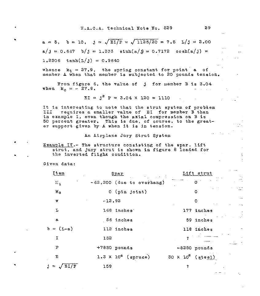
Z.A.C.A. Technical Mote.Wo. 529 29
a = 5, b = 10, j = J-Ey5= JYizgz-= 7.5 j-1/j = 2.00 -. --- a/j = 0.667 b/3 = 1.333 sinh(a/j) = 0.7172 cosh(a/j) = --
1.2306 tanh(L/j) = 0.9640
whence kt = 27.9, the spring constant fo,r point' a of member A when that member is subjected to 20 pounds tension.
Prom figure 6, the value of j for member B is 3.04 when kc = - 27.9. .-
31 = j" P = 3.04 x 120 = 1110 .
It is interesting to note that the strut system of problem 1Z.i requfres a smaller value of EI for member B than in example I, even though the axial compression on B is 50 percent greater. This is due, of course, to the great- er support given by A when it is in tension.
An Airplane Jury Strut System s .
Examgle IV.- The structure consisting of the spar, lift strut, and jury strut is shown in figure 8 ioaded for
. , the inverted flight, condition.
Given data:
Item -- slzr . 1.1 1 -62,200 (due to overhang]
g3 0 (pfn joint)
W -12.92
L 168 inches'
8 56 inches
b = (L-a) 112 inches
I 152
P +7830 pounds
E 1.3 X lo6 (spruce.)
j = JTE7F 159
Lift strut -
o--
0
0
177 inches
59 inches - ~ --
118 inch-es
? --__
-8250 pounds
.-
?
--

30 F.A.C.A. Technical Note No. 529 .
Given data (continued):
Item __ ._--
L/j
. . -IJff-t strut Gnar. , -_.-_._ _.
1.057 '? . . - ? L -.
a/j . .- . ;3521 -.;, .
sinh a/j, .3593
cash a/j
sinh L/j
1.0626 , l
1.2652
cash L/j
tanh L/j
l,i;l26. . -7845
M$;i is the'end moment due t-o the cantilever overhang. The axial loads are.computed in t-he ordinary manner, i.e.‘, using the given data f-or side loading.
A strut size must be selected which, first, will al- low the system to reIi;a.in .e,lastically stable, and second, which will not cause a supporting load on the wing spar that is large enough to stress it be:;ond the modulus of rupt7zre.
The Frbcedure is much f-he same as in the previous ex- amples; but a slight approxination and a COTTeCtiOn are necessary because of the angularity between the jury strut and the,-lfft strut.
It, is quite obvious that as the force in the jury strut of figure 8 is not normal to the lift strut, there is
an axial component imposed on the lower bay of the strut, As the supporting force mill be quite small in proportion to the tote1 axial load in the lift strut, the above axial component may be noglcctcd with no very great error.
As noted above, a correction :aust also be made to COP- pensatefor tile angularity of deflection and supporting force of the wing spar to the lift strut; this correction will be. made on the spring constant of tho strut. An ex- aggerated view of the system when doflocted is given in figure 9. In this figure ab and alb' represent t?re jury strut in the undeflected and deflected positions, ro-
-.- .-
-.
c
*
.

N.A.,C.A. Technical Note No. 629 . _. 31
spectfvely. Points a and b are assumed to deflect in directions sormal to the members when they are in the un- deflected positions. If aal fs assumed to equal bb", the deflection of the lift strut (bb') eq,uals the deflec- tion of .the spar' divided by COB cd (aa!/cos a). The above assumption i$ made on the basis.that alb' equals albll, whkch fs obviously untrue. Rowever, the error involved is very small for the small deflections~allowable in ordinary structures. Thus‘, if CabI = 18 inches, bb' = 2 iLnche8, and sin a = l/3 t b'b' ' = 2 sin a = 0.67 inches. Thus, a'b' - albf I '= 0.67/(2X18) = 0.0125 inch which, in com- parison with 2 inches, may be neglected. AS the deflec- tion bb' would be much less than 2 inches in practice, the assumption that alb' = alb*' i6 justified.
It is also apparent (f%g. 9) that the supportfng force normal to the lift strut (W,)opposes a-force equal to the load on the jury strut (mb) times cos a, that is, Ws (Strut) = - Wb (spar) X cos a.. Thus, from the above,
and
6b co= (war) = Ss (strut)
Bb (spar) = - & (strut)
(20)
(21)
and dividing (21) by (20)
(Spar) = -- 1
(COB Cc) (strut)
or kb (spar) = k, (strut)/cosa a (22) - Raving the necessary corrections for the special
case in which the strut and supporting beam are not paral- lel, we may now proceed wfth the calculations in the con-
'ventional manner, using equation (9).
The initial deflection of the SpaT 60, can be com- puted by the method outlfnea in section IV of the Appendix.
6 =- (23)
Since we have uniformly distributed side load, when x = a

32 N.A.C.A. Technical Note No. 529
Ma - (Ml + Wj2> cash (L/j) + wj2 sinh a M = -c-- -_ sinh (L/j) 3
+ oh + wj’) cash 5 - wj2 3
Substituting the given data in the above axpressions, we obtain:
hf = i 1199
MO = - 949
MO ” M = +2-50 .
s -250 = --- = -250 P
- = - 0.0320 inch 7830
The spring constant of the spar i6 obtained from equation (4)
1 kg-
a b + j sinh" (a/j) -c;;~-~-~-- - j sinh a cash - 3
Substituting the given data gives kt = +2800
In order to facilitate the selection of the bsst size of lift strut for this structure, a curve (fig. 10) of ' ks v60 j ma6 drawn as in example I. The calculations f-or figure 10 are shown in table II of section V of the Appendix. This curve shows that the spring constant of the strut changes very rapidly from the critical point to value6 of j in the neighborhood of 33. This indicates that the best strut size is one having a value of j near the sharp break in the curve (about j equals 33). It is quite ap arent region P
that reductions of strut siee below this J = 33) are accompanied by a very high rate of
change of k, which, of tour se, causes the support-ing force W of equation (9) to increase very rapidly. On the other hand, if a larger size strut is chosen (with a larger value of j), very little is gained in reduction of supporting force W because of the small rate of change of spring constant above j = 33.
.
*

Z.A.C.A. Technical Note 30. 529 33
Accordingly, the value of k, in figure 10 at j = 33 is found to be -380. Applying the correction derived above in equation, (2): Since
--
CO8 a = 56 z-0 95 59 l
corrected k, = -380 ---- (0.96-y = -' 421
Calculation of We from equation (9)
We = - 0.0320 X 2800 --- X 421 2800 - 421
where - 0.0320 = So
2800 = kb
-421 = ks
whence .
WV=- 15.9 pounds supporting load on spar (down).
Since the value of j for the strut is 33
I = [.33)2 X. 8250 30 x lo6
= 0.2995 *' -
For comparison, a strut having a value.of j = 32 will be tried. From figure 10, k, = -- 520 at j = 32. Corr-ect- ed
k, = -520 ---. (0.957
s- 576
w = - 0.0320 X 2800 X 576 = -_--- - 280C - 576
- 23.2 Founds
'L I = 0.282
\ . .

34 N.A.C.A. Technical Note No. 529 . I . . . ..a
Thus Re see that a 6-percent reduction of I causes a 34-percent increase in W. .'
' . It is'interesting to m&e.a comparison of 'ihe size of
tube needed when the strut is supported-and unsupported. The size of- an unsupported t,ube is:
and or
L/j = Tr for unsupported strut L = 177 inches J = 177/n = 56.3 -_ -’
The nearest commercial size of the above supported tube having a value of, $ F 0.282 would *be 2-l/4 by 0.083 inches and for a length of 177 inches would weigh 28.3 pounds. -The size of the unsupported tube having an I of 0.872 would be 3-l/4 by 0.120 inches and would weigh 59 pounds, or twice as much as the other. It is quite evi- dent that the reduction in weight due to the jury-strut system is quite worth while. 0: course, the weight of the jury strut should be added, in the case of the 6UgpOrted Btrut, but as the above calculations show, this member carries such a small load that it will be a relatively small tube.
Ln ordor toselect.,the.best point to connect the jury Gtrut, some idea must be had of the deflection curve of the spar .due to external loads, for it is obvious that if the jury strut happens to be connected to the point of zero deflection, the supporting force is zero. been mentioned before, hoiever,
It-has that this could only be
true for one particular loading.as'the point of zero de- flection moves as a function of the axial load in the spar. Nevertheless, this movement is relatively small and a connection in the vicinity of the zero'deflect-ion point is the most logical place to.make a joint. Accordingly, a deflection curve of the spar due to the external loads in example IV has been prepared (fig. 11). This curve show6 that the jury strut in the above'example- wa6 placed close to the point of zero deflection. Due to'the lack of knowl- edge at the I;resent time of the actual wing loading which occurs, it is possible that the externa$ deflection at the jury-strut connection is much greater than the assumed loading predicts, Some calculation should accordingly be made to determine just how serious and how large the sup- porting force might be under some extreme 'condition. For- mula (9) shows, however, that no extremely rapid change
T-
.

I~:.A.C.A. Technical Bate Bo. 529 35
may take place as W changes only in direct proportion to the initial deflection 6oti For an actual numerical calculation, SUppOSe the deflection at the jury-strut con- nection due to.some very unusual loading should equal the maximum deflection shown by the curve. This appears to be as unusual a condition as might be encountered because, under ordinary loads, the deflection of the above psint' Is -.-- - . very small.
From the curve, we see that the maximum external cle- flection is about 0.15 inch. Taking the same values used abovo in the calculation of W for a strut having a value of j=32:
W = - 0.15 X $zx 576 = = 109 pounds - 576
Thus, for an extreme case, the supporting load is only 109 pounds, mkich does not appear to be excessive. A check should be made, of course,
--. .__ of the bending moments 0.Ccur-i
ring due to the 109 pounds concentrated load added to the external loading. z.
- .- The above calculations deal with support in one plane
only. In most dosigns of today, the lift strut has a streamline section so that no support is necessary in the wind direction. Eowever , if a round tube is to be used, some means of side support must be made in another plane besides that one calculated in-example IV. This is pro%- ably most easily accomplished as shown in figure i2. A-s. a and b would both have approximately the -same deflec- tion under a given loading condition, point c will have very -little horizontal deflection. indicate that (ca)
The above-assumptions will carry very little load. If the
designor feels that a more precise calculation should be made, the method used in example IV may be used if some corrections are added to take care of the angufarity'of -- the members of figure 12. _.
36 W.A.C.A. Tschnic'al Yote No. 529
PART II
EXPERIMENTAL INVESTIGATION OF FORWLAS
1 By Reid Bogert
I. APPARATUS AND TESTS
The tests conducted to check the validity of the foT- mulas derived in the first part of this paper were carried out on an Olsen 20,000-pound, hand-operated, testing ma- chine located in the Materials Laboratory at StanfordUni- versity. The apparatus required for the tests is shown in the photographs of figures 13, 14, and 25, and in the de- tailed drawings of figures 16a to 16e and, except where otherwise noted, was constructed from cold-rolled steel- bar stock. The principal parts of t.his appa'ratns are an upper loading bar, (II) a'lomer 'loading bar, (III)(:) tie rod between the mnfdspan points of the beam and strut, e IV) a pulley system for applying side load, and (VI a screw nfcrometer for measuring deflections.
The upper loading bar had five 120-degree notches milled in the top surface to take ago-degree hardened steel knife-edge-mounted on the head of the testing ma- chine; On: the bottom surfbce of the upper loading bar and the top surfa,ce"of the lover loading bar there were corre- sponding pairs of g°ree notches take test members ia compression. of the upper and lower lo'ading .bar-s
~tf~~~r~~~~~.~~~~a~~~s~o a. slot was milled to
take fittings for the tension test members (figs. lba,b,e).
The tie rod is shown in deta-il in figure 16~. This rod was required-to prevent relat'ive lateral movement.of the midspan points of the beam and strut and no-t*-o inter- fere nith the bending in the beain and strut. '1-t was con- structed of two side pieces separated by four blocks, lon- gitudinally adjustable to take different sized test mem- bers, and held in position by four machine bolts passing through slots in the side pieces. The whole assembly, supported by rollers resting on a standard fitted into the lower loading bar, was free to move laterally.
Horizontal side load was applied to the midspan point of the test beam through a length of piano wire, at- tached to the tie rod and passing over a ball-bearing

N.A.C.A. Technical Note No. 529 37
pulley, to which was fastened a weight pan-loaded with shot bags. The pulley was supported on an arm extending from the lower loading bar.
.-
The screw micrometer was a l/4-inch steel screw threaded through a micarta block. It was mounted on a bar pivoted at the lower loading bar and slotted at the upper so that vertical movement of the upper lqading bar was un- imFed.ed (fig. 16d). The scale of the micrometer was cali- brated to 0.025 inch and a dial to 0.001 inch. Contact of tho micrometer screw with a bolthead mounted on the tie rod closed an electrical circuft containing a small flashlight bulb and battery.
Test members were made up from solid, cold-rolled steel-bar stock.
3/8, Compression members were l/2 inch in width and l/4, or l/2 inch in thickness. All were 20 inches long
and mere ground to 60-degree knife-edge ends.
The tension member was 1 inch in width and l/4 inch in thickness. Special end fittings were requfred (fig. 16e) and the length between supports was 22 inches. -
Values of ES in lb. in.2 were determined for all test members from bending tests. The members were simply supported on knife-edges and deflection measurements made for side load applied at midspan.
- The experimentalry de-
termined values of EI were as follows.*
Test Members
No . Size Type EI lb.in.2
1 l/2 by l/4 inch compression 19,000
2 l/2 by l/4 inch II 19,000
3 l/2 by 3/E inch II 67,000
4 ., l/2 by 3/E inch If 67,000
5 l/2 by l/2 inch II 156.000
6 - 1 by l/4 inch tension 39,500 ----- --- ------ ---- *The bending test data and calculations for EI were given in Bogert*s thesis, but are omitted from thfs report to conserve spacea Ed.

38 N.A.C.A. Technical Yote No, 529
The set-up for tests with tho beam in compression is shorn in tho g-h-otograph of---figure 15. The test members were placed at A and 9 (figs, LSa, 16b) and the external load at various positions between A and Be
The. set-up for t0st.s with the beam in tension is shown $11 the photograph of figure 14, The strut .nas placed at B and the beam at C (figs. 16a,'16b). The external load was placed .at various positions .outside of 9,
Deflection measurements were made tit the midspan points,on each of two sizes of compression members tested as struts nhen supported at the midspan point by each of three sizes of compressdon members and the tension member as beams, $or.each .co.mbination of test members, the posi- tion of the 'external ioad on the loading bar was varfed, thereby varying the proportions of.loads 2-n the beam and strut,- and f.or .each combination of members and positfon of externql load, tfie value of the side load was varied.
The test program was as follows: (Positions of mem- bers and load as shownin fig. 16a.)
Schedule of Tests
Test .
.Member at 'Total l.oad Side loads
a acting at fn pounds
A- 1 #5
-2 5
- '3 '5
B-l '5
- 2 5
-3 5
G-1 4
-2 .4
B C
#3
3
3
1
1
1
3
3
4
3
2
4
3
2
4.
3
0 - 15 - 30
0 - 15 - 30
0 - 15 - 30
0 - 10 - 30
0 - 10 - 30
0 - 10 - 30
0 - 10 - 20
0 - 10 - 20

K'.d.C.A. Technical Xote 30.529 39
Schedule of Tests (Cont.)
Tast
D-l
-2
-3
E-l
-2
F-l
-2
-3
G-1
-2
-3
Member at Total load acting at
A B C
3,l 4
3 1 3
3 1 2
2 1 4
2 1 3
4 6 5
4 6 3
4 6 1
1 6 5.
1 6 3
1 6 1
Side loads in pounds
o- 5-15
o- 5-15
o- 5-15
o- 5-10
o- 5-10
0 - 15 - 30
0 - 15 - 3p . .
0 - 15 - 30
o.- 10 - 15 ---
0 - 10 - 15
0 - 10 - 15
In making the tests, the test members were first set up in the apparatus, in a vertical position, and just suf- ficient total load applied to hold them %n place. The fTe- rod blocks were adjusted so that the loading edges were' in contact wfth the test members, and the clamping nuts tight- ened. Total load was then increased and the deflection of the strut with no side load measured. Such deflections were due to initial eccentricity in the test members and, as it was desirable to elimfnate the effect of this ecce-n. tricity as much as possible, readjustments of the tie-rod blocks were made untilthe deflections obtained with no side load were the minimum possible with the test apparatus. Data for deflection and total load were then recorded for - - the condition of no side load and incremeln.ts of the total load from the minimum to a maximum just under the faflure load. Similar runs were made for the beam subjected to constant side loads. In every case initial and final de- flection readings were taken for the minimum total load Rith and.without the side load. '

40 '1J.A.C.A. Technical Note No. 529 .
II. DISCUSSION
Scopeof Tests -
The formulas of Part I were developed for the analy- sis of a- structure consisting of a pin-ended strut sup- ported at any point, through a.tla rod perpendicular to the axis of the strut, by a parallel beam axially loaded and subjected to side loads, Application of the formulas to an airplane jury-strut system, in which the strut and beam are not parallel, required the use of correction fac- tors for-the relative angularity of the members. In these tests, however, a set-up was used similar to the condi- tions for'which the basic formulas were derived. Due to limitations in time, it was possible to investigate but one position for the tie rod and one type of side load on the beam. The position chosen for the tests was the mid- span point on the strut and b-earn, for at this point it is obvious that the deflections obtained would be greatest, and the relative effect on the deflections of inaccuracies in the set-up would be-least. The spring constants of the beam and strut, however, depend upon their geometrical di- mensions and the typ-e and value of the axial loads. The spring. constant, then, for a given etrut, varies with a change in posit-ion of the tie rod when the axial load is held constant, and varies with the axial load when the po- sition of the tie rod is held consizint. In the tests, the effect of a change in the value of the spring constant was investigat-ed by varying the axial load, The agroement be- tween the theoretical and experimental results, however, indicated that the change in spring. constant due to axial load was correctly accounted for .bythe. formulas. It is reasonable to'conclude, therefore, that the formulas would also be correct for a variation in spring constant due to change in the position of the ti.8 rod.
-
.
The lateral loading applied to the beam in the testi consisted of concentrated loads applied at the midspan, or supporting point, on the beam, The formulas, however, show that stability of the strut and beam. system is unaf- fected by the side load, although the position of equilib- rium of the system is dependent upon the deflection of the beam at the supporting point due to the side loads. In each of the test runs the side load was kept constant: Since the deflection of the beam far a constant side load is a function of the axial load, the variation in the ini- tial deflection of the beam covered a wide range. If the

N.A.“,. A. Technical Xote Bo. 529 41
stability of the system were dependent upon some function of the initial deflection, the effect would then be appar- ent in a comparison of the theoretical and experimental re- sults. As no such general effect is evident from the curves of ftgures 17 to 26, it can be conc~udeStJi$z the stability of the system is independent o-f the inftial de- flectfon,and therefore of the type of side load. -Tt seems, therefore,
-- that the present tests are sufficient proof of
the validity of the formulas for any conditions.
Apparatus
As the apparatus required for the making of these test5 was, of necessity, someThat complicated, some c.omment on the difficulties involved in its development and opera- tion seems advisable.
Axial load was applied. simultaneously to the two test members through an upper and lover loading bar in which pin- end ponditions for the test members were obtained by using knife-edge loading points. The apparatus and test members were constructed from cold-rolled steel and no‘.attempt -%a8 made to harden the knife-edges., Only on test member h, which was subjected to the greatest ioads, however, was any mutilbtion of the knife-edges evident. tests with beams in tension,
In prelimihary.
through circular pins. the tension member was loaded
The deflections obtained, however, -were considerably smaller than the results of theoretical calculations indicated. It was thought that this might be due to friction in the loading pins, so the pins were _-..- ground down to provide a simple knife-edge-support (fig. 16e). Although this did not completely eliminate the presence of friction, the agreement between the-theorefi- cal and experimental deflections was greatly improved;. The effect of the alteration is shown in figure 25. - * --
Some difficulty was encountered in satisfactorily ad- justing the tie rod to reduce the effect of initial bow and knife-edge eccentricities-, test members,
especiall-y in the--larger This difficulty was due -primarily.to the
design of the tie rod, the adjustment of the loading blocks of which was made by sliding clamping bolts in slots. A suggested improvement, but one which limitations Of time made impossible to take advantag-e of-for these‘: tests, would be an arrangement for adjusting -the blocks - . longitudinally by means of screws.
.

N.A.C.A. Technical Note Xo. 529 ,
In a preliminary study of the apparatus requir.ed for -. the t--e st s , it was thought that the deflections could be measured on a calibrated dial scale, the pointer of which was fastened to a small pin rotated by the movement of a wire attached to the tie rod, wrapped once around t?~.pi.n, and loaded with the side lo.ad weights. For the desired magnificationofthe deflections, however, it was neces- sary to use a pin of such small radius that wire WCS not sufficiently flexible to nrap.around it, A strong cord was used, but due to friction in the pin bearings and elasticity of the cord, the method nas entirely unsatis- factory. The apparatus mas then altered and side load ap- plied directly through a nire, passing over a large-diame- ter ~?_~lley carried on ball bearings, as. shown-in figures 14 and 15. Deflectton mas.measured by means of the screw micrometer, used in the final tests, but mounted on a bar fastened only to the lower loading.bar. It was found, how- ever, that due to uneven action of the loading screws in the testing machine used, one side of the head of the ma- chine was pulled down before the other, thereby giving It a slight lateral movement. As this motion was transmitted to the upper ends of the test members the deflection read- ings were affected. Several other testing machines were tried but the same motion of the head was presenf in a greater or less degree-in a.l.1.. The deleterious effect of this movement on thedeflection readings was finally elfm- inated by mounting the micrometer on a bar fastened by sin- 'gle bolts to both loading bars, In order that the sup- porting bar should take no vertical load from the upper loading bar, the slot, shown in figure 16d was provided in the upper end of the supportfng bar. This method pro- vided a parallelogram motion and maintained a constant distance between t-he micrometer support and the normal un- -_ loaded position of-the strut.
Precisj.on of Dimensional Quantities.and Measurements
The dimensional quantities and measurements for the apparatus and tests were made as accurate as was practi- cable with the set-up.
Dimensions of the test apparatus and test members' were made to an allowable variation of jX.025 inch. The maximum possible error in the value of the axial load fq the beam or strut would then be abEt- percent and a max- imum error in the initial defle.ction of the beam due to the length of the strut would .be about l/3 of 1 percent. A valid quantitative estimate of the probable error due to
N.A.C.A. Technical Rote No. 529 43
.
inconsistencies of the material, initial bend, or slight eccentricity of the knife-edge ends of the test members is impossible.
The value of EI in 1b.in.s used for 'each of the test members in the theoretical calculations, is the aver- age of a number of experimentally determined values as found from bending tests. The maximum variation of EI determined from these tests was about 3 percent. This would indicate a possible error in the initial defleetion of the b-earn of about 5 percent.
Side load in the tests was applied by weights, in the form of canvas bags filled with shot, placed in a light sling. The sling weighed approximately one quarter‘pound -- .. but this weight was neglected in the computations under .. the assumption that it would be balanced by friction in the pulley assembly and in the rollers supporting the tie rod. An error in this assumption would affect the deflec- tions directly in proportion to the ratio of the error to ' the side load. The canvas bags were 5, 10, and 25 pounds in weight and their- values were checked on a balance scale to within an ounce.
Values of the total load were read from the balance arm of the testing machine to the nearer five pounds, and corrected for a tare weight of 80 pounds. Small errors -in- this quantity would have a negligible effect when plotted to the scales used for the curves. Readings of deflection .-- were made to 0.001 inch and estimated to 0.0001 inch. It was assumed that movement of the head of the testing ma- chine vas small enough to neglect the effect of rotation of the -axis of the screw micrometer and that play in the pins holding the micrometer support Fras negligible.
The deflection values used in plotting the experimen- tal results in figures 17 to 26.are the djfferences between the deflection readings for the corresponding total load and side load, and the deflection reading for.the minimum total load and no side load. . The validity of these de- flection measurements therefore depends npon the assump- tion of a negligible deflection of the system for the con- dition of the minimum total load and no side load. -An ex- amination of the curves of deflection for no side load in figures 17 to 26 will show that the rate of increase of' deflection is small for low values of the total load. The assumption is therefore justified.

44 N.A.C.A. Technical Note No. 529
Zxperimental Curves
The experimental and theoretical data are shown in figures 17 to 26 in the form of curves of deflection as a function of total load. The agreement, in general, bo- tween the curves is sufficiently within the possible ex- perimental error to justify'the validity of the formulas.
In the theoretical formulas it is assumed that ideal conditions of loading and material of the strut and beam' are obtained. In the actual $5ase this is impossible of realization, as there is always some slight heterogeneity of the material or small eccentricity in loading which will affect the action of the strut or beam. In the pres- ent tests it was found impossible to eliminate the doflec- tions of the strut under the condition of no side load. These deflections, however, were reduced as much as possi- ble and were in the direction in which the side loads were applied for all the test-s. From a consideration of the curves it can be seen that, in general, initial differences in the experimental and theoretical curves are increased aa the load increases untfl a value of the load near the max- imum is reached. At loads approaching the maximum the curves tend to more nearly agree. The major exception to this is in test 0, in which the beam is in tension. Fric- tion in the loading pin is undoubtedly the cause of the high maximum loads, in comparison to the ideal condftion, obtained.
Attention is called to the fact that the scales of deflection for all the tests are similar although the load scales vary for different combinations of test members.
Practical Application of -Result-s
A study of the experimental curves of figures 17 to 26 inclusive shows that, in general, the effect of initial eccentricities becomesless important as the L/P ratio of the strut and the initial deflection due to side load on the beam increase. Bending moments on the strut due to small eccentricities, however, are relatively unimportant when compared with the moments induced by the deflect.ion of the system. For minimum bending moments the deflec- tion of the supported point due to side loads on the beam should be as small as possible. The jury strut, in an air- plane jury-strut system, therefore, should be connected to the wing spar at or near the point of zero deflection for the design load. This point will usually be near the
.

N.A.C.A. Technical Xote Bo. 529 45
point of inflection. The point of zero deflection, how- ever, will move as the load on the spar is reduced ahd t-he initial deflection at the supporting point will then be increased. This increase in initial deflectioa, in spite of a reduction of the external loads may cause the criti- cal bending moments on the strut to be those for a loading less than the design load. The designer-should take this possibility into account unless further study of the gen- eral problem should prove this to be unnecessary.
A curve has been includea in figure 25 to show the effect of friction in pin bearings on the deflection char- acteristics of a jury-strut system. Friction is evidently desirable from a consideration of structure rigidity, since it materially reduces the deflections by inducing restraining end moments in the strut and spar. Such re- straining moments in pin bearings, however, are small, and should be neglected in practical design.
In test BS, in which were tested the smaller strut and the largest beam, bending occurred in the unsupported semispans of the strut before the midspan point of the strut had reached a maximum deflection. The strut assumed an S shape rather than the usual simple bow. This bend- ing in the individual spans was first noticeable at an ax- ial load in the strut of about 1,750 pounds, which gives, for the whole strut, a value of and, for the semispans a value of L/j
L/j = 6.0 = 3.0. In no other test was
there any apparent S bending of this type in the unsup- ported spans. The maximum load, however-, on-the smaller strut (No. 1) was obtained in test Gl for a total load of 910 pounds. In this test the load in the strut was 1,910 pounds and L/j of the semispan was 3.17. The max- imum load on the larger strut (Xo. 4) was 3,820 pounds in test Fl corresponding to a value of L/3 of 2.45 for the semispan. It vi11 be noticed that, while bending in the unsupported spans occurred in test B3 at a value of L/j = 3.0, there was no noticeable bending in the unsup- ported spans in test Gl for a value of L/j = 3.17, or slightly more than rr. The curves show, however, that, in test Gl, the maximum load mas obtained at a deflection approximately five times that of test B3. AlthoFgh the results of these tests are not, in any nay, Conclusive evi- dence on this point, they aould indicate that the restraint coefficient c, for the unsupported spans, increases as the deflection at the point of support of. the strut in- creases. It may be remarked also that the midspan .poPnt of. .--

46 lJ.A..C,B. Technical Note 20. 529
support, used in these tests. Teuld be expected to be least ef~fective in increasing the restraint coefficients for the individual spans. If the strut rfere s~p~oo~ecl at the midspan point by a rigid support, the individual spans of the strut could act as simple pin-ended struts, the mho2.e strut bending in an S shape. If the point of sup- port were shifted to either side of the midspan point, how- ever, the shorter unsupported span nould provide an end. re- straint to.the longer span, As the airplane jury strut is usually located betmeen the third and mid points of the strut, an invest-igation of the eff-ective restraint coeffi- cients nhen an elast-icsupport is used at locations oth0r than midspan would be highly desira3le.
An interesting observation, from the results of these tests, is that for the type of set-up used, and if the beam and strut are the same length, the maximum load car- ried by the combination is approximately the same-regard- less of the proportion of?load in the beam snd strut. The maximum total load is reduced only slightly as the propor- tion of load in the strut is increased.
III. RESULTS
The resultrs of the tests described in this paper are shown graphically in the curves of figures 17 to 26, in- clusive.* Theoretical curves, calculated from the formu- las for t-he corresponding test conditions, are included- as a basis for comparison. The values of total load for the experimental curves have been corrected for a tare weight of 80 pounds, and the deflections given are equal to the difference between the d.efl&ci:ion reading for the corresponding total load and side load and the deflection reading for the mi:limum total load and no side load.
-wl_-_--__ d--____----- __A....._ __-- ----._---------
“These i? i g1J.r e S co7er onl; about half of the tests made, but t--hey inciude those in which the divergences between the experimental and theoretical curves are a maximum as well as those in which they are a minimum. As these ten sets of curves are a fair sample, including both the best and the poorest experimental r-es-ilts, the other nine sets have been omitted to conserve space. 'Ed.

The are c2.rIT eauatior, preceded tions ii2 ZLS possi commorl 6
3 .B.C .A. Technical h’ot e X0. 529 47
Xomenslature
derivations of formulas in the following sections ied out parallel to the derivations of the Newell s in Chapter XI of reference 2. Formula numbers
by the letter W denote references to the equa- that book. The nomenclature used is also, .50 far
ble, the saxe as that employed by Newell. The more ymbols and their meanings are as follorrs:
iil+ensitTF " J of drstributed lateral load in lb. per in., positive mhea acting upward.
magnitude Of concentrated lateral ioad in lb., positive rrhen acting uprrard. !
1 bending moment in in. lb., positive when it tends to cause com-pression in the upper fibers of the beam.
slope of elastic c'urve of the beam in radians, positive when the tangent rises from left t0 right.
deflection in in., positive Then the deflected po- sition of a moint is above the original position.
axial load, lb.
modulus of elasticity of the material, lb. per sq* in .
moment of inertia of the section in in?
length of span between supports in inches.
distance to a section from %he left end of the span in v;hich it is located, in inches.
distance from t.he ieft end of the span to the point of application of a concentrated side load. --

48 N.A.C.A. Technical Not-e No. 529 .
Derivation of the Extended Three-Xoment Equation
with Deflection of Supports
The first step is the derivation of formulas for a single span beam having a uniformly distributed side load, axial compression, and deflect,ed supports. It must be noted that the axial load P is not in line with the sup- port points but is always parallel ._-_---- tp the base line f-ram ----I_-- which 6 is measured. (See fig. 27.)
Taking moments about support (2), we have for R1
wL,2 ;.I, - 14, R1 = --5-L- -
-__---- + P (61 - 6,) ___------ 1 Ll Ll
and the moment at-any point is wx2 l[zy, + -- - 2 c VII 1 lJ2--M, P&-&2) ---
2 ~------~+~-.~~~----
Ll .Ll > x L p (y*&,)
(a.11
(A.2)
This expression is the same as that obtained in reference 2 l-p- 188) , equation (W 1l:l) except for the addition of the deflection terms.
On differentiating twice with.respect to 2, the de- flection terms varnish and the differential equation ob- tained is the same as that given on page 188 of reference 2 for the case without deflection of supports. As the boundary conditions are the same for the two cases, the expressions for M, equation (W 11:2), including even the constants of integration, are also identical for the t;vo cases. The same would be t-rue for any other condition of side loa~d, SC me find the interesting fact that the ex- pression for moment in a span of continuous beam in terms of the end moments and side loads on the span is independ- e I-2 t of any deflection of--the supports. This does not mean that the moment in the span is unaffected by such deflec- tions, since the end moments are definitely influenced by it as mill be seen below, but only that- the formula for intermediate moments in terms of end moments is unchanged,
The effect of supportideflection reappears when we obtain an expression for deflection at any point in the

span by substituting the value of El from equation (x ll:2) in equation (A.2) and solving for y. This gives an ex- pression identical to (N 11:6) except for the addition of the deflection terms
The slope of the tangent to the elastic curve at any point is obtained by differentiating the deflection equa- tion, This gives an equation identical to (K 11:7) except for the addition of the deflection term
1 _ - F (6, - 6,)) ----I---- P ( L i
Three-Xomeat Zquation
The three-moment equation is obtained in exactly the same may as described in article X1:3 of reference-2 eon page 190. The final equation is exactly the same as equa- tion(X 11:ll) extent for the addition of the deflection terms .
6 .-.- (hi -- - 6 > z -.--A!!?..-- 6 (6 - ----zL.- 6,) 3 i- .- L i + -_----. L2
It should be noted that after X2 has been obtained for a specific case by means of the three-moment equation, a deflection term must be added in the calculation of the reactions of the beam as indicated in equation (A.1). Thus, the deflection term ' (6, - 621/Li must be included in the expression for I?, and -P (6i - 52) LI in the ex- pressior- for La.
SECTION III
Derivation of Spring Constant for a Dean
Subjected to Axial Tension
In order to determine the spring constant for a point on a beam subjected to axial tension, it is necessary to develop the formulas for the deflection of a beam of this type due to a single concentrated side ioad 3. Such a
.
.
beam and the forces acting on it are shonn in figure 28.
T h e bend.ing :?oneilt at any point in the span nil1 be
IL = !i, -t- p 5 (8.3)
vher 8 Ii& is the bending moment d-ue t.o the effmect of the end moments, M 1 and Ma, arid the transverse load 'ii, ~Ci.l- ing alone, nhile Ii? y is the secondary momonir-due to the aerial ioad and the deflection. In Ghhj.s case, with the on- ly side load a concentrated one, the variable x does not appear in x0 to any power but the first. On differon- t iating twice with respect to x, therefore, the term MO disappears and the expression for moment becomes
The sol.ntions of this differentis eouation are
M i = c i sinh & -+- x C2cosh 1; 3he 13 X=a j
(A. 4-) J
xi, = c, sinh when x = a (A.5) c
Althou{:h the general form 0.. f the equatj.on for mo:lient is tke same for the two sections into which the beam 1s ,di- vided bLr the supporting load, t-he presence of t'hat load makes it aocessary to use two equations with oeparatu con- stants of integratj.on for the two sections of the beam.
Three of the cons.tants of integration can be Gvxluat- ed from the boundary cond.itmions that
X .z L, M = 142
*y z a , K, is the same, rcgardlcss of which equation Fs used.
For t 1-i. e fourth constaat of integration, the simplest method of eva.luation is to and (A.5) with respect to
differentiate equations (.A.=%) x, thus obtaining expressions
for the shear on sections normal to the elastic curve of

N.A.C,A, Technical Vote No. 529 51
the bea=. When x = a, these shear expressions should give values nhich differ by the amount of the concentrated load W.
Proceeding along these lines, me obtain
11 &‘a M i a (-j, = __-- L
- W j sinh P ------ -
sinh 5 tanh $' -W j coshy
3
Id2 - (Xl - U j sinh % cash $ c3 = -l_--l---------l- L------ J. -7
C4 = 14, - V j sinh % J
FOG purposes of con?puting deflections, equation (8.3) ma5; be written
y = c (23)
Substituting the values of id from (A.5)
equations (A.4) and
y Ix - 5 (h-c, SiEh $ w Cl& cash $) when x=a (A.7)
Since, in the case in which -ire are interested, the beam is assumed pi?--ended, X1 = X2 = 0.
MO = -3 b x/L nhen x= a and MO = -IV a(L-x)/L nhen*x= a
Vhen x=a at the supporting poi-r?t, the deflectfon Y=8 can be obtained by substituting these qualities in either equation (8.6) or (A,'7), whence
a P ba sinh j a
7:- = -- ,- - Kt
T + j sinh : i'--- 'tanh $
cash L J 1 3, (A.8)

52 X.B.C.A. Tec!lnical Xote No. 529
02” 1 1 /ab j sinh2 (a/j) a ---.._- ---- -
3r-L -- r. F (1 + -tanh (Y7j) a\ j sinh Y cash -; I
J 3 (4) i
Deflection of a "oeam Subjected to Axial Tension
The deflections of a beam subjected to axial tension and any side load may be abtained from formula (23) above if proper changes be made in Mo and. ?I to allow for the difference in the type of side loading.
When the side load is uniformly distributed over the span the deflection can be obtained from the formula given in reference 2 for this case. (See p* 208.)
D2 - D, L cash 7 IL X x I[ zzz ----I_ ---_-
L sinh - 4 I?, sinh 7 2
cash - - v js 3
J
The formulas for this and other types of side loading can also be obtai.AedPmfrom fcrmulas fomr the same type of side load and axial compression by the follorTing procedure,
1. Substitute for each triga;cm&:ic function the corre- spondiag hyperbolic f~unction,
3. Reverse the sign of 7g j" : but not that of w jl where it appears.
3. Substitute -2 for +F to indicate the effect of changing the character of the asial load in tile formula for deflection. Applying the se rules to the case of a side load varying uniformly from CT lb,,/in, at the left sUqrort

X.A.C.8. Technical Note Wo. 529 53
to (w -I- kn) lb./in. at the right support, F'C havs*
ji zz c, sir;h X cash-;-- J
iThere
IQ, +- (1 -I- k) B j” - (E, + m j”) cash s;! (yl = -.-----l_--- ----- I_--- L!-
L silih Y J
*ITote that k but the ratio span l
.---___ -_---____--- __-_l_---_-__-l___ in these f ormulns is oot a spring constant betmo en the side loads at the ends or" the

‘ote 170, 529 54
. SE,:? 108
Computation of S-grizg Constant
TBzLT!J i: Calculations fo
xamples
6*
.eri cal
4igur .----
j ---- 4.545
4,363
4.167
4.OGO
3.846
3.571
3.333
2.941 ----
a I -r 1 -t--
1.10 I-
1.15 I
. 1.20
i 1.25 I
! I.30
i .j -----
2.20
2.33
2.40
2.53
2.60
_-I___
1.0912
1.1009
1.11l.4
1.1225
X.1345
1.40
1.50
1 .-.70 j 1. ----.
2.80
3.00
i.167_0
1.1915
3.40 ----
L.2673
- Ps
_ --___- 1.6124
1.7325
1.8854
2.0864
2.3518
3.3963
7.3486
*3.0787 --- --
1 I- i i
j- / kc
t----- .I. I j
I I
I!
- L.---.---
21.580 1 i.1590 I
-3.293
-6.100
-8.625
22,829
24.402
26.476
29.290
39.768
79.443
-24.451 ------
1.3407
1.5607
1.8385
2.2000
3.4653
7.9443
-3.1404 ---_
I I
!
'-10.950
-13,090
I -17.070
)-20.980 .
.
. i i-31 ,640
Cl- -u C is compu.ted
L
fTOZ equatioo (LG) ,

TA3TJ ii: Cc;lcaiat Lens for kc of Figure iO* -----
j ----- 31
32
34
36
4Q
45
50
56,34 ---A-
-. I I -t-
i
I
/
I
---A-
a 7 J ----
1,093
1.844
I.735
1 -.640
--- ‘0 -; J ----
3.808
3,688
3.470
3.278
-I -,47s;2.350 1
1.312j2.622
1.180 2.360
1.048j2.094 ---I- i--
-- I ,i- I-
/ i i 1 I i
I i
I !
A.
---..----
Ti f-L
------. ~1.3723
1.3382
1'.2833
1.2423
1.1839
1.1401
1.1072
1.0819 -------
-. .----- $2
-_----- -0.7970
-1.1242
-2.3537
-6.3943
5.5875
2.4367
1.8195
1.5105 m--u--
--- ii i- I I i B
I- / i ! ! I
,-. * l1 C is compyJ,teii from equatior? (. 18
-_--_-- il 3,-tb, P2 r -_-~- -13.080 f- -53.702 I
-202.022 / ,
-68X.231.
729.175
354,797
280,026
242.083 .i -------
---___ 8
----- -0.1706
-,6870
-2.290
-8.550
5.970
2.295
1.469
1.000 .---~

56
SECTIOB VI
Samples of Experizental Data and Deflection Computations
Xlthougll it has seemed advisable to omit most~ of the detailed egporimental data and deflection curves, it a-p- pear s advi.sai;le t.o include samples of t1ii.s part of the mork in order t-o shoiu a little more clearly how the curves of figures 17 to 26 Bere obta.ined. Por this purpose the experimental data for test E- 1 reductions or"'the. general formulas for the special cases studied, and values computed fr0R-i th0Se fora~~las for the theoretical curves for tests X-1 and Q-l a.re g; ,ven in t';Lis section of the Appendix.
Experimental Data - Test X-l
---.-_ ---J
._I_. .* 3,s. IJ, 20 0 340 0.0003 550 .03Oi 73 5, .0044 a55 .0097
30 - .OOc12
__. 17. s . L , 20 5 lb. 20
195 295 415 540 705 805 U-70
20 N.S.L. 20
.I i
1 at B
6
0 0.0252
,0293 .0332 ‘0402 .0521 .0781 ‘1205 . 1849 .0261 .0013
Load at 4
Pm,
7, 2t.s.L. 20 10 lb. 20
135 300 420 535 660 735
20 7: s 7 1. , *A. 20
s .---__L 0 0.0460
.0539 *Ofi *OS09 a0998 l 1465 .1718 a0476
-.0002
For locations of loads and specimens, see figure 16.
P'S 3 total. lcad indicated by testing machine corrected for tare Foight of SO pounds.
8, deflection of r-lid-point of specimens measured from po- sition i7it.h minimum total load and no side load.
37. s . L . indicates tile condition of xiniaum total load and no inside load.

.
P
P a*
3.
B.A.C.A. Technical Xote Bo. 529 57
Xeduction of General Fornulss of Part I for the
Special Cases Investigated Experfmentally
Beduct? of equation (3) for the spring constazt of 0.5 L a str-ut in cozipression for the case where a=
= b.
Equatioo (3) is
1 1 ab -- = c - J-k (
-- + j_-si n2 I? L
--lSL.Jl L j sin 2 cos 5) tar (L/j) j 3
Substituting a for b, 2a for L, azd A a j /
P - G- =
F-5 j pd&+ - sic A cos A \ i'
for
= g - L tan A 2 2
(9.6)
Reduction of equation (4) for tke sprFng constant of a strut in tension for the case There a = b = 0.5 L.
Equatroa (4) is
1- ( a\ k; -
S (a-5 + j sixth2 a p \L
LJJ- - j sinh F cosb T 8 tad2 (L7jj Ji
Substituting a for b, 2a for L, and A for a j, /
F 2 + j /sinb2 A CO;?~ A - l
sinh A cash A \ -= kt s i.Eki /

58 N .A . c . A . Technical Note Wo. 529
P -- = a_ + j sinll---- @ A (ash 211 - 2 cash' Al) -----CL---- ------ : e LLt 2 2 sinh A cash A i
E a, - !I. --L--- 2 2 c 0 t 22 A
(A.7)
C. Derivation of formula for deflection of support -point when the only external load on the beam is a concen- trated force at the support point,
1n the case represented by the tests, the initial do- flection of the beam &o. can be obtained from the spring constant of that member. Thus
6, = S/k3
vhcre S is the side load in pounds
k”b, spring constant of the beam in pounds per inch.
Substituting this relation in equation (8) to deter- mine the deflection 6, of the combination of beam and strut , rfe have
]I- u 60 S 6 = ---___ = ------
k:?, -i- k, k-o -1- L;, (-4.8)
Xumerical Values of Spring Constants
T!lo values of the spring constants for specimens 1 2lid 2 ic. compression, and specimen G in tension, are given -DeloTi. The constants for s-oecimcns 1 and 2 were computed from eil_uation (A.S), tion (8.7).
and those for specrrren 6 from equn-
.
-
.
.

3 I A , C.A. Technical Kote 170. 529 59
Spring Constants for Specimens 1 arid 2
Size l/2 by l/4 inch Ei = 13,000 lb,iz~.~ a = 10 inches - -~
Axial load compression --
F
0 60
100 120 140 150 180 200 210 220 240 250
kc
-!-114.0 59.1 9c.3 85.4 80.3 77.9 70.2 65.8 63.7 GO.5 56.6 53.4
F
289 300 350 375 400 420 440 450 430 500 525 560
I
-f I
i
i
kc
44.9 41.5 29.4 22.8 17.1 12.2
7.1 4.3
-5,7 -7.7
-13.6 -22.1
T I
i-
F
600 625 6'60 700 750 770 840 875 880 300
1000 1050
kC
-32.3 -38.7 -47.3 -58.1 -70.3 -75.0 -92,6
-101.1 -102.9 -108.8 -133.5 -147.0
Spring Constants for Specimen 6
1200 1225 1250 1260 1400 1470 1500 1680 1750 1875 2100
! -Ii- I /
-186.0 -193.2 -199.5 -202,2 -240.0 -258.8 -268.5 -317.5 -337.' -377.5
I -445.0
Size 1 by l/4 inch Zi = 39,500 lb.in.' a = 11 inches
I --g-E&
40 l.86:8 60 191.5 70 193.2 80 294.5
100 197.5
Axial load tension 7 2 kt i F j kt 1 F
I 120 203.5 350 ! 255.2 800 140 209.0 400 270.0 880 160 212.0 440 1 274.0 180 218.5 600
I I
900 307,5 1320
200 222*1, 660 320.0 .I0540 220 226.2 329.8 1760 300 243.5 344.5 1980
I 352.0
I I
368.2 372.2 461.0 509.5 551.0 600.0

.~
P -T
0 200 400 500 SO0 700 800
-
T
N,d, C.B. Technical Tote X0. 529 60
Theoretical Geflections for Test E-l
Bear2 30. 2 Strut No. 1
Fb j ps
0 1 0 60 140
120 230 150 350 130 420 210 490 240 ( 560
t
I I / ! c
i k-b i k, i J++.k, j ---oe---
i I s = 5,= 10 Ii-
4114”.0 fii4.0 4228.0 99.1 30.3 179.4 85.4 44.9 130.3 77.9 29.4 207.3 70.2 12.2 82.4 63.7 -5.7 58.0 -01 5" 6 -22.1 34s5
I
0.0219 .0278 .c383 .0465 .0607 #OS63 .1450
, I
0.0438 .0556 .0'766 .0930 .I214 .I.726 .2900
PT -__
0 200 400 600 7CO 800
Theoretical Zeflections for Test G-1
pb=l.10 PT(tens.) P -8 =2.10 P+Ozip.)
i ! F-, ] F, 1 kg I I ks -kyi-k, i b
j s-- = 10, = 15 -- L I 1 I
I
0 0 -+177.6 t114.0 G-291.6 220 420 226,2 12.2 23a.4 440 8~0 274.0 -92.6 1.81.4 SSO 1260 321.0 -202.2 118s 770 1470 344.5 -252,a 85.7 880 lS80 368.2 -3i.7.5 50.7
Sta2fo:d University, Cal if 0 Tili2 , Bebruarp 1935.
0.0343 .0419 .G551 .084i
iL68 : 1970
0.0515 .0628 .082'1 .1263 .I750 .2958

Zigs. 1,3,4
7i q-r-2 - -:. 1.

B.4.C.A. Technical Note No. 529 Fig. 2

N.A.C.L. Techical note 270. 529 Figs. 5,7,8
10 lb. - External side load for exazpl e 2 Oril~.
3
7’ I 5"
II
---7
/ c 3, \
A Fipze 5.
szc i E
-
3
I x-
-0’
7;’ -37 ,
C a
T-
Fisn-e 7. ?-

N.A.C.A. Technical Bate X-0. 529 Fig. 6
Spring constant, k , lb./in.

N,AiC.A. Technical Botc No. 529 Figs. 9,12
Fig-ire 9.
Fi,gxi-e 12.

N.A.C.A. Technical Kote ?To. 529 Fig. 10
cn 0
Spring constant, k , lb./in. ii c-l Y
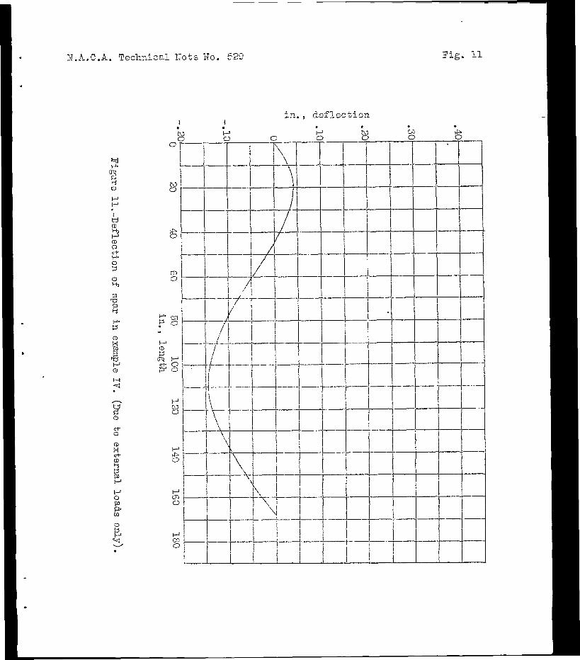
1T.b.C.A. Techniczl Kote 30. 529 Fig, 11

11.A.C.A. Technical Note No. 529 Figs. 13,14,15
Figure 13.
Figure 14.
IFigure 15.

.
N.A.C.A. TecImical Wote No, 529 Fig. 16
(a)
I I ’ LJ b)
I
i j -p F
-y--i- 4. / I
T --
f-J- J
-
-
--- E
-. -
-14 s-xi..- _. - -
P
i
(a) TJpper loading bar. (d) Xici--on?eter szpmrt. (b) Lower fl 'I (0) Tension: nmber fitting. (c) Tie rod (f) Strut dimensions. P
Figure 15.-DetaFls of test apparatus.
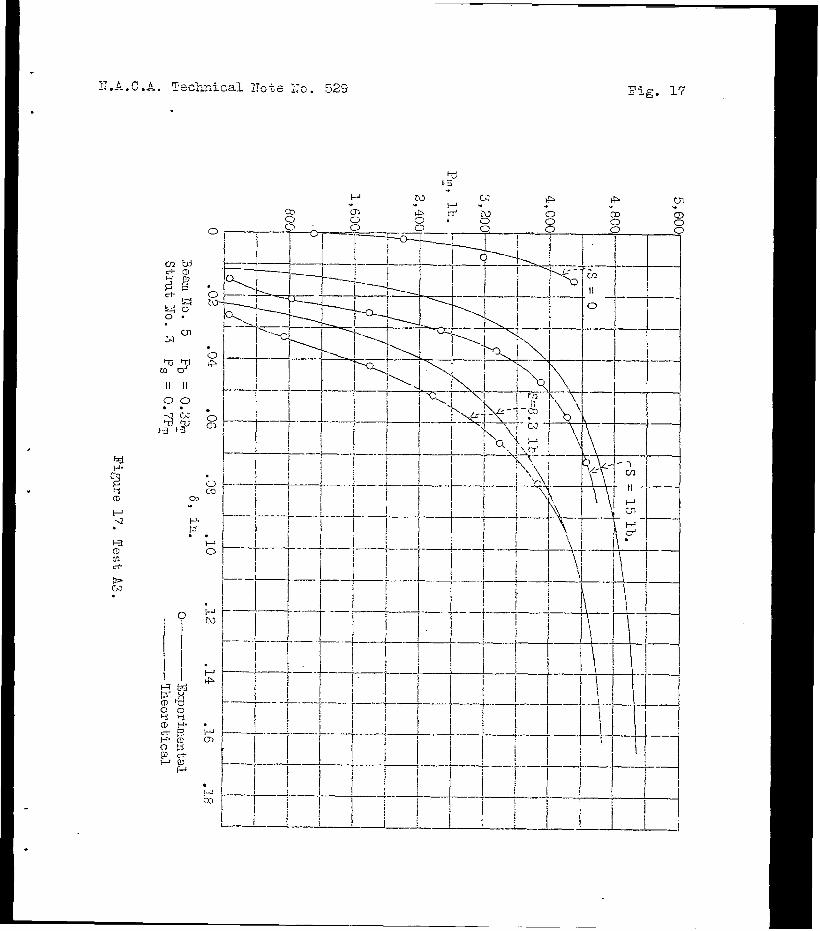
i- A C.A. -I .--. TecLmical 1Jote 2;s. 529 Fig. 17
i’ 2 P i2 .

E.A.S.A. Sechniczl. Note X0. 529 Fig. 18
-r
! 1 I-T-
! I I I

Tig. 19
” v ” ” v
Y---I I I i ! i I ! i i ! l-7

.A. Techical Bote No. 529
w w Lnd
II II 00 . . incn

N.A.C.A. Techical Note X0. 529 Fig. 21

,
.
N.A.C.A. ToclrA.cal ZToto 170. 529
00 . . -.l bi
Fig. 22

Fig. 23
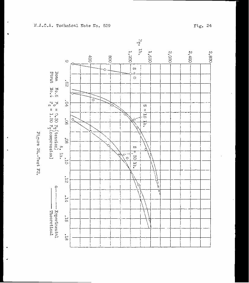
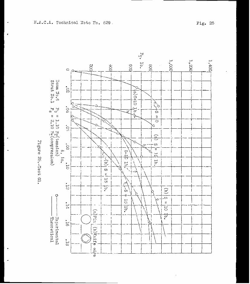
3.lL.C .A. Techdsal Xote 1To. 529 Zig. 25

N.A.C.A. Tec.hical Note No.529 Fig. 26
T-

N..k.C.A. Technical i?ote No. 529 Figs. 27,28
F I------ L+ ! L i !
si
!A 1 = h!! = 0 for pin exls
Figwe 28.