buckling/crippling of structural angle beams produced ...buckling/crippling of structural angle...
TRANSCRIPT

Buckling/Crippling of Structural Angle Beams Produced using Discontinuous-Fiber Composites
Tory Shifman, Brian Head, and Mark Tuttle
Department of Mechanical Engineering, University of Washington, Seattle WA
Abstract
The underlying objective of this four-year study is to determine how well the mechanical behavior of discontinuous-fiber composite (DFC) structural components can be predicted using properties inferred from simple coupon level measurements. During the tests discussed herein DFC angle beams were subjected to monotonically increasing bending loads until failure occurred. Beams with three different cross-sections were studied. Several replicate tests were performed for each beam type. Two of the beam types failed due to pronounced buckling/crippling of the compressive flange. In contrast, the third beam type exhibited little/no buckling. Rather, for this beam failure occurred due to near-simultaneous fracture of both flanges. Finite-element analyses of the three beam types were consistent with measured results. 1. Introduction
Discontinuous Fiber Composite (DFC) components produced using sheet-molding compounds are now being used in commercial transport aircraft. The use of DFCs is driven by the fact that (relative to continuous fiber composites) these materials allow compression molding of large numbers of complex parts at relatively low cost. In addition, DFCs provide high delamination resistance, near quasi-isotropic in-plane stiffness, high out-of-plane strength and stiffness, and low notch sensitivity. However, structural analysis of DFC parts is challenging since there are no widely-accepted methods of analyzing such materials. As a result, certification of DFC parts is currently achieved by testing a large number of parts (i.e., certification by “Point Design”). This is time consuming and costly and may lead to over-conservative part designs. In order to transition to a more desirable certification process based on analysis supported by test evidence, material allowables and related analysis methods must be developed to reliably predict the performance of DFC structures.
This study is focused on HexMC®, a DFC sheet-molding compound produced by the Hexcel Corporation. HexMC prepreg consists of randomly oriented and distributed ‘chips’, which are produced from unidirectional AS4/8552 pre-preg. Individual chips have a nominal thickness of 0.125 mm and in-plane dimensions of 8 mm x 50 mm. Since chips are randomly distributed the number of through-thickness chips varies modestly from one point to the next, and consequently pre-preg thickness is not as well-defined for HexMC as for continuous-fiber pre-preg systems. Eight chips typically exist through the thickness of a single HexMC ply, corresponding to a pre-preg ply thickness of roughly 1 mm. To produce a part multiple layers of plies are placed within a closed metal die and compression molded using standard practices. Following molding individual chips/plies are completely intermingled, so the original interface between neighboring plies cannot be distinguished. The interface between individual chips is readily apparent, however. Micrographs showing the surface and edge of a compression molded flat HexMC panel are shown in Fig. 1. Feraboli et al measured the elastic properties and failure strengths of HexMC [1,2,3]. Tensile properties were measured using coupons prepared according to a Boeing standard [4]. It was shown that HexMC can exhibit surface strain gradients of about 20% when subjected to simple uniaxial tension. Consequently material properties normally used in subsequent structural analyses, such as the elastic modulus E or tensile failure stress/strain for example, also exhibit this level of variation. Relatively large gage lengths must be used to infer nominal properties from experimental measurements. In light of these large strain gradients and associated variations in elastic properties, it is not known how well the elastic behavior of HexMC structures can be predicted using nominal properties and standard analytic/numerical

Edge Micrographs Surface Image
Figure 1: Typical HexMC images
techniques. Therefore, the objective of this study is to determine how well the behavior of DFC angle beams subjected to pure bending loads could be predicted. Angle beams were selected for study since they are relatively inexpensive to produce and test, and yet they represent a relatively “complex” structure, at least as compared to simple tension or compression coupon specimens. Two different rounds of bending tests have been performed. Results from the first round of testing were reported earlier [5]. Briefly, in the first round of tests relatively low magnitude bending loads were applied, to insure that strictly linear-elastic strain levels were induced throughout the beams. The bending moment vectors were applied at six different orientations with respect to the beam cross-section. Thus, in many tests the bending moment vector was not aligned with the principal centroidal axes, resulting in a condition of unsymmetric bending. Bending stiffness and orientation of the neutral axis were measured for all orientations considered and compared with predictions in each case. Measurements were qualitatively well-predicted, in the sense that the orientation of the neutral axis was well-predicted in each test and strains increased linearly with distance from the neutral axis. Quantitatively, the effective bending stiffness exhibited essentially the same level of scatter as reported by Feraboli during the simple coupon tests [1,2,3]. In the second round of tests, reported here, a bending moment is applied at a single orientation and increased monotonically until fracture occurred. At least five replicate tests were performed for each of the three beam sizes. The measured response of each beam is then compared to predictions based on a finite-element analysis performed using NASTRAN. 2. Description of the Angle Beams The angle beams studied were manufactured at Hexcel using standard production procedures. As-delivered beams with three different cross-sections were provided and are shown in Figure 2. Dimensions of the beam cross-sections are defined in Figure 3, and numerical values are provided in Table 1. In the following discussion the three specimen types will be referred to as the large, medium, and small angle beams.
Flan
ge L
engt
h
Flange Thickness
Figure 2: Compression-molded HexMC angle beams Figure 3: Angle Beam Cross-Section

Table 1. Beam dimensions and area properties
Flange length, f (mm)
Flange thickness,
t (mm)
Centroid position, c (mm)
Major mom of inertia, Iz (cm4)
Minor mom of inertia, Iy (cm4)
89 4.8 24 52.1 22.9 64 4.8 17 32.2 7.74 44 2.5 12 5.44 1.28
As delivered, the large, medium, and small angle beams had lengths of 710mm, 355 mm, and 550 mm (28 in, 14 in, and 21.5 in), respectively. Upon receipt all beam specimens were machined to a standard length of 355 mm (14 in) using a surface grinder equipped with a diamond-coated abrasive cutting disk. 3. Description of the Test Fixture The 4-point bending test fixture used is shown schematically in Figure 4, and a photograph of a composite angle mounted within the test fixture is provided in Figure 5. The fixture is designed to accept beam specimens 355mm (14 in) in length. The specimen is clamped within a 1-in thick grip at both ends, so the grip-to-grip beam length is 305 mm (12 in). An overall load P is applied to the fixture, resulting in a bending moment M = Pd/2 applied to the central angle beam, where dimension d = 25.4 cm (10 in) and is defined in Figure 4. The composite angle is clamped within two circular aluminum plates, which are in turn bolted to outer circular steel plates welded to the left and right loading beams. A bending moment orientation of 180°, illustrated in Figure 6, was used during all tests described here. This arrangement placed the upper flange in compression and the lower flange in tension.
P/2
P/2 P/2
P/2
Composite beam
d dStrain gages
Plated bolted together
Figure 4: Four-point bending test fixture Figure 5: The assembled four-pt bending fixture
M
Figure 6: Orientation of the bending moment M
4. Measurements A typical response for small beam specimen S3 is shown in Figure 7, where the load and the corresponding bending moment are plotted against crosshead displacement. A linear response was observed for bending moments less than about 3500 in-lbf. A pronounced buckling/crippling response of the compressively-loaded flange occurred at higher load levels. The buckling response was readily apparent, as shown in Figure 8. Five replicate tests of the small beams

were performed. Measurements for all five beams are superimposed in Figure 9. Although load-deflections curves were not identical, virtually all small beams exhibited a pronounced buckling of the compressively-loaded flange at load levels well below the final fracture event. Final fracture was due to a bending fracture of the buckled compressive flange. The bending moment at the moment of final fracture ranged from 4650-5700 in-lbf, as indicated in Figure 9.
Figure 7: Load-deflection measurements obtained during testing of small angle beam S3
(a) Appearance of specimen S3 at a bending load of
about 3000 in-lbf
(b) Appearance of specimen S3 at a bending load of about 4600 in-lbf
Figure 8: Photos illustrating buckling/crippling of the flange loaded in compression in small beam S3
0
1000
2000
3000
4000
5000
6000
0
100
200
300
400
500
600
0 0.1 0.2 0.3 0.4 0.5 0.6
App
lied
Ben
ding
Mom
ent (
in-lb
f)
App
lied
Load
(lbf
)
Crosshead Displacement (in)
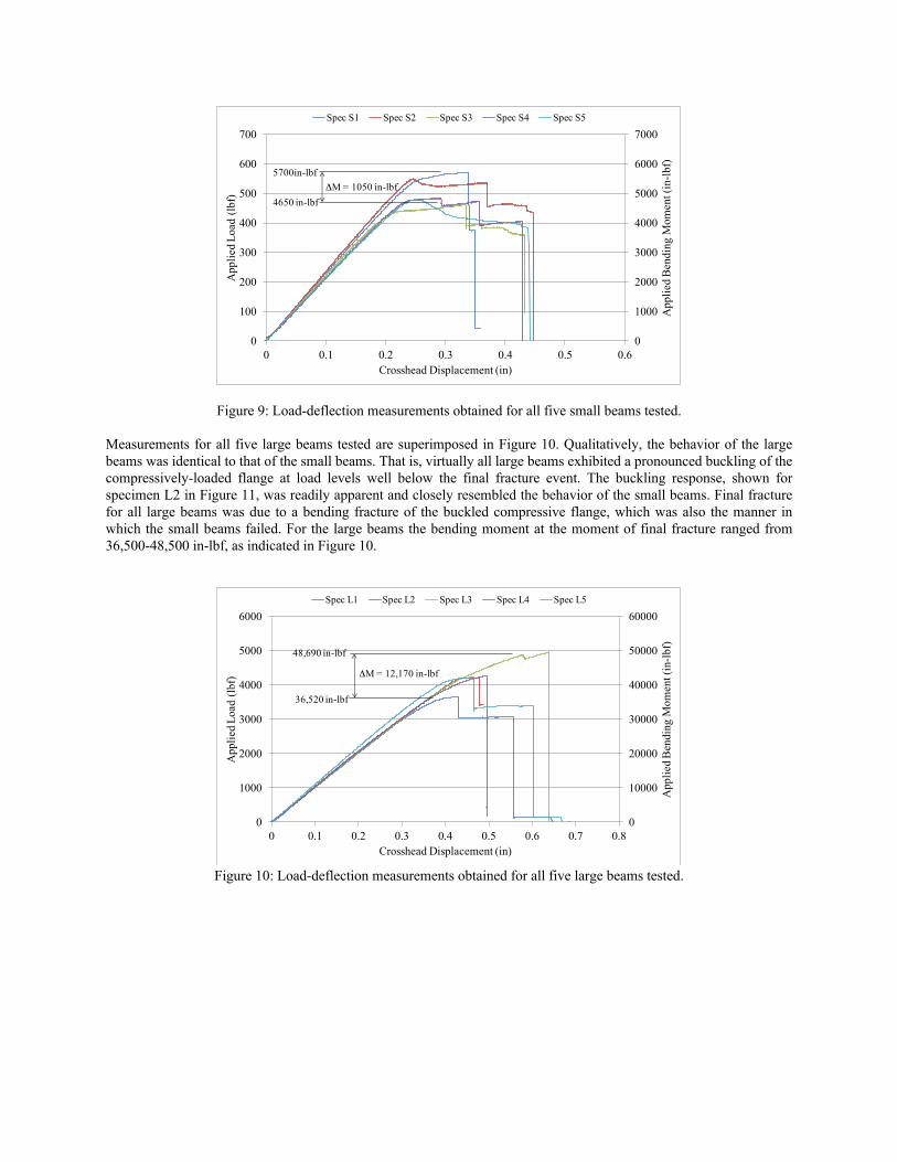
Figure 9: Load-deflection measurements obtained for all five small beams tested.
Measurements for all five large beams tested are superimposed in Figure 10. Qualitatively, the behavior of the large beams was identical to that of the small beams. That is, virtually all large beams exhibited a pronounced buckling of the compressively-loaded flange at load levels well below the final fracture event. The buckling response, shown for specimen L2 in Figure 11, was readily apparent and closely resembled the behavior of the small beams. Final fracture for all large beams was due to a bending fracture of the buckled compressive flange, which was also the manner in which the small beams failed. For the large beams the bending moment at the moment of final fracture ranged from 36,500-48,500 in-lbf, as indicated in Figure 10.
Figure 10: Load-deflection measurements obtained for all five large beams tested.
0
1000
2000
3000
4000
5000
6000
7000
0
100
200
300
400
500
600
700
0 0.1 0.2 0.3 0.4 0.5 0.6
App
lied
Ben
ding
Mom
ent (
in-lb
f)
App
lied
Load
(lbf
)
Crosshead Displacement (in)
Spec S1 Spec S2 Spec S3 Spec S4 Spec S5
ΔM = 1050 in-lbf4650 in-lbf
5700in-lbf
0
10000
20000
30000
40000
50000
60000
0
1000
2000
3000
4000
5000
6000
0 0.1 0.2 0.3 0.4 0.5 0.6 0.7 0.8
App
lied
Ben
ding
Mom
ent (
in-lb
f)
App
lied
Load
(lbf
)
Crosshead Displacement (in)
Spec L1 Spec L2 Spec L3 Spec L4 Spec L5
ΔM = 12,170 in-lbf
36,520 in-lbf
48,690 in-lbf

(a) Appearance of specimen L2 at a bending load of
about 30,000 in-lbf
(b) Appearance of specimen L2 at a bending load of about 42,000 in-lbf
Figure 11: Photos illustrating buckling/crippling of the flange loaded in compression in large beam L2
In contrast, the medium beams exhibited little or no buckling behavior prior to fracture. Seven medium beams were tested, but the data for specimen M1 was lost; results for the remaining six specimens (M2-M7) will be discussed here. The load and corresponding bending moment measured for the six medium specimens are plotted against crosshead displacement in Figure 12. Comparing these results to Figures 9 and 10, it is apparent that the response of the medium specimens was far more linear than that of the small or large specimens. Failure of three of the specimens (specimens M5, M6, and M7) occurred due to direct compression fracture of the compressively-loaded flange, whereas simultaneous failure of both the tensile and compressive flanges occurred for the remaining three specimens (specimens M2, M3, and M4). In these latter cases complete fracture of the entire cross-section occurred. Also, there was little visual evidence of buckling of the medium beams, as shown in the photos of specimen M3 presented in Figure 13.
Figure 12: Load-deflection measurements obtained for five medium beams.
0
5000
10000
15000
20000
25000
30000
35000
40000
45000
0
500
1000
1500
2000
2500
3000
3500
4000
4500
0 0.1 0.2 0.3 0.4 0.5 0.6 0.7
App
lied
Ben
ding
Mom
ent (
in-lb
f)
App
lied
Load
(lbf
)
Crosshead Displacement (in)
Spec M2 Spec M3 Spec M4 Spec M5 Spec M6 Spec M7

(5) Appearance of specimen M3 at a bending load
of about 30,000 in-lbf
(b) Appearance of specimen M3 at a bending load of about 37,000 in-lbf, just prior to fracture
Figure 13: Photos of medium specimen M3 during testing
These experimental results clearly demonstrated that the compressively-loaded flanges in the small and large beams buckled well before fracture, whereas buckling did not occur (or was minimal) prior to fracture of the medium beams. In general, the onset of buckling is dictated by the relevant dimensions of the structure involved (in this case the relevant dimensions are the flange length and thickness, listed in Table 1), and the modulus of the material, in this case the modulus of HexMC. Hence, the next step was to determine whether the experimentally-observed behavior of the HexMC angles (buckling of the small and large beam, but no buckling for the medium beams) could be predicted based on a finite-element analyses and the elastic modulii measured by Feraboli [1,2,3] using simple coupon specimens. 5. Finite Element Modeling The beams were modeled in Femap, a pre/post processor for the NX Nastran solver. They were modeled using 4 noded rectangular plane elements at the mid-plane. They were modeled as being 12 inches long with all nodes along the each end of the beam being fixed to a node at the centroid of the mean by rigid elements. This condition simulates the clamping aluminum plates. One end of the beam was fixed in all six degrees of freedom and the other was fixed in x translation and rotation about the y and z axes at the respective centroid nodes with the axes as indicated in Figure 14. These conditions simulate the rotation allowed by the fixture. The load was applied as an enforced rotation of the left end of the beam about the x axis at the centroid, which is also the neutral axis. Figure 14 shows a sample of the mesh of the large beam with ends fixed and the rotation applied. All three beams were modeled in the same manner. During preliminary modeling, solid elements were also used, but offered no increase in solution quality, but greatly increased solution time.
Figure 14: Large Beam Mesh, Loads and Constraints

The enforced rotation was applied gradually as a function of time, and the solution was obtained using NX Nastran’s Advanced Nonlinear Solver. Figures 15-17 shows plots for each beam size of the maximum stresses in the tensile and compressive flanges versus the bending moment applied to keep the right end from rotating. The two curves represent the high and low values of elastic modulus measured by coupon tests 7.66 and 5.10 Msi [1,2,3]. The black vertical lines represent the compressive and tensile strength ranges reported by Feraboli et al [3].
Figure 15: Small Beam
Figure 16: Medium Beam
0
1
2
3
4
5
6
-80 -60 -40 -20 0 20 40 60 80
Ben
ding
Mom
ent (
10^3
in-lb
f)
Stress (ksi)
7.66 Msi 5.10 Msi Strength Range
0
5
10
15
20
25
30
35
40
-100 -80 -60 -40 -20 0 20 40 60 80 100
Ben
ding
Mom
ent (
10^3
in-lb
s)
Stress (ksi)
7.66 Msi 5.10 Msi Strength Range

Figure 17: Large Beam
With these plots, it is desired to predict if the beam will buckle prior to failure, or failure will precede significant buckling behavior. If the onset of significant buckling behavior is taken as the divergence from linear behavior by more than 10%, it can be seen that the finite element analysis predicts significant buckling behavior before failure for the small and large beams and very little or no buckling prior to failure for the medium beam, assuming that higher modulus corresponds to higher strength. For both the small and large beams it can be seen that as the bending moment increases, buckling occurs before the stress reaches the respective strength. For the medium beam, it can be seen that the low modulus response reaches the tensile strength limit well before buckling. For the high modulus, the tensile strength is exceeded just after buckling behavior is exhibited. Figure 18 shows the medium beam with high modulus just prior to failure. It can be seen that it has just started to buckle, which agrees with the observed stress behavior seen in Figure 17.
Figure 18: Medium Beam High Modulus at 24,500 in-lbf
The flange in which failure is initiated can also be predicted. For the small beams the stress is exceeded in the compressive flange first for both the low and high modulus. For the medium beam, which flange fails first (i.e., the flange in tension or compression) depends on the assumed modulus value. This explains the inconsistent failures observed during testing of the medium beams. For the large beam, the high modulus exceeds the strength in the buckled compressive flange first. For the low modulus, the strength is exceeded in the compressive flange first, however a very slight error in the strength could change this.
0
5
10
15
20
25
30
35
40
-100 -80 -60 -40 -20 0 20 40 60 80
Ben
ding
Mom
ent (
10^3
in-lb
s)
Maximum Stress (ksi)
7.66 Msi 5.10 Msi Strength Range

Table 2: Bending Moment Comparison Experimental Buckling
Moment (in-lbf) Predicted Buckling Moment (in-lbf)
Angle Low Limit High Limit Low Modulus Percent Error High Modulus Percent Error Small 2325 2850 2612 21.5 3207 16.6
Medium 17500† 20000† 17050* N/A 22050* N/A Large 18260 24350 16380 2.4 21750 3.6
†Buckling did not occur before failure *Predicted to fail before reaching load The predicted and measured bending moments necessary to initiate buckling are listed in Table 2. For the small and large beams, the buckling load was over predicted by an average of 3% and 19.4% respectively. For the medium beam, the beam failed at an average of 97.5% of the predicted buckling load. 6. Summary and Conclusions The objective of this study is to determine whether the nominal modulus and tensile strength of a DFC HexMC material system, measured using simple tensile coupon specimens, can subsequently be used to predict the buckling and failure behavior of HexMC angle beams subjected to pure bending loads. Compression-molded HexMC angle beams with three different cross-sections were tested to failure, and measured results were compared with predictions based on a finite-element (NASTRAN) analysis. Overall, good agreement between measurement and prediction was achieved. The FE analyses predicted that the compressive flanges of the small and large angle beams would buckle well before fracture, which is precisely what was observed experimentally. In contrast, according to the FE analysis the bending moment necessary to cause buckling of the medium beams is nearly identical to the bending moment necessary to cause fracture. This prediction also agrees with measurement. The only significant deviation between measurement and prediction was that the magnitudes of the bending moments necessary to cause buckling of the small and large beams were over-predicted. Since buckling loads are notoriously sensitive to geometric and/or loading imperfections, these discrepancies are reasonable. The next step in this four-year project is to study a more “complex” HexMC structure. A HexMC intercostal has been selected for this purpose and is currently being tested. A comparison between measured and predicted elastic and fracture behaviors will be presented at a future meeting. 7. Acknowledgements The authors gratefully acknowledge the financial and technical support provided throughout this study by Dr. Larry Ilcewicz, Ms. Lynn Pham, and Mr. Curt Davies of the FAA, Dr. Bill Avery of the Boeing Company, and Mr. Bruno Boursier and Mr. Dave Barr of the Hexcel Corporation . 8. References 1. Feraboli, P., Peitso, E., Cleveland, T., and Stickler, P: Modulus Measurements for Prepreg-based Discontinuous
Carbon Fiber/Epoxy Systems, Journal Composite Materials, 42-19 (2009), 1947-1965. 2. Feraboli, P., Peitso, E., Deleo, F., Cleveland, T., Stickler, P.B., “Characterization of prepreg-based
discontinuous carbon fiber/epoxy systems: Part I”, J. Reinf. Plastics and Composites, Vol 28, No 10, pp. 1191-1214, 2009.
3. Feraboli, P., Peitso, E., Cleveland, T., Stickler, P.B., Halpin, J.C., “Notched behavior of prepreg-based discontinuous carbon fiber/ epoxy systems”, Composites Part A, Vol 40, pp. 289-299, 2009.
4. Boeing standard test method for unnotched tension, D6-83079-61, The Boeing Co. 5. Shifman, T.J., and Tuttle, M, E, “A Study of Structural Angle Beams Produced using Discontinuous-Fiber
Composites”, presented at the 2011 JAMS Conference, 20-21 San Diego, CA (presentation slides available at http://www.niar.wichita.edu/niarworkshops/Workshops/tabid/123/Default.aspx)