technical notes from the berlin 2 hdpe geomembrane ... · the ultimate workshop objective was to...
TRANSCRIPT

1
Technical Notes from the Berlin 2 HDPE Geomembrane Workshop:Assessing Remaining Service LifeReport authors: Dr. Ian D. Peggs, P.E. and Helmut Zanzinger
1.0 INTRODUCTION
Nearly all engineered systems have a finiteservice life. This includes geomembrane(GMB) barriers (liners) as part of the system forthe containment of valuable product (potablewater, gold solutions, etc.) andcontaminated/obnoxious liquids/solids (coalash, meat processing waste, etc.). All exposedhigh-density polyethylene (HDPE) GMBs willdegrade by oxidation in service and fail byquasi-brittle stress cracking. Clearly, facilityowners need to know when a liner will no
longer perform its containment function.
On 26 September 2014, the day after the endof 10th International Conference onGeosynthetics (ICG) in Berlin, Germany, aworkshop of international experts was held atthe Federal Institute for Materials Researchand Testing (BAM) to discuss “development
of a protocol to determine the remainingservice life of an already exposed HDPEgeomembrane liner”. This followed two
shorter workshops on the same topic atEuroGeo 5 in Valencia, Spain (2012) and atGeosynthetics 2013 in Long Beach, USA.
2.0 OBJECTIVES OF WORKSHOP
The ultimate workshop objective was to develop a protocol that would describe the actualcondition of an exposed HDPE GMB, to predict its remaining service life, i.e. the time before theGMB can be expected to fail, and consequently needs to be repaired or replaced to preventsuch failure. The discussion was limited to HDPE because of its globally common use in majorsectors such as waste and mining and because its durability characteristics are better
understood than those for other liner materials.
Figure 1. The "BAM Leak Detector." Dr. JP Giroud(Berlin 2 Facilitator) pauses outside the
proceedings to appreciate the intersection ofengineering and art.

2
A skeleton protocol to catalyze the discussion was proposed as follows, based on theassumption that final failure of HDPE GMB would occur by surface oxidation and stress
cracking:
1. Measure oxidative induction time (OIT) to assess whether or not oxidation protection isstill available.
2. Measure carbonyl index (CI) to assess extent of any oxidation that has occurred.3. Determine if there is a critical CI at which stress cracking (SC) is initiated.
4. Measure stress cracking resistance (SCR) to determine the time until SC is initiated.
Note well that the intent was to discuss barriers already installed that have been exposed to theenvironmental synergisms that cannot possibly be reproduced in the laboratory. It was not todiscuss accelerated testing on virgin materials in an artificially generated environment todetermine their expected service lives.
3.0 DIFFERENTIATION BETWEEN BURIED AND EXPOSED APPLICATIONS
3.1 Buried GMBs
Mechanical stresses in GMBs occur only during installation (under “ideal conditions”)
and if we ignore folded wrinkles (according to “North American practice”).
After installation, stresses in GMBs relax and GMBs are practically “stress-free” (under
“ideal conditions”).
The classical “3-stage aging model” (antioxidant {AO} depletion time + induction time +
polymer degradation resulting in a modification of the mechanical behavior of the GMB)
described by Hsuan & Koerner (1998) is reasonable because the service life, often
presented as time to reduce mechanical properties, defined with an acceptance criteria
of the original value is sufficient for an ideally designed and ideally installed, buried
GMB.
However, buried GMBs are not the topic of this workshop!
3.2 Exposed GMBs
The full designed stress (or more) may occur at any time – even after many years in
service! Therefore, End of Life (EoL) should be based on 100% retained or design-
based strength as 100% of the expected stress may occur at any time.
“2-stage model” (AO depletion time + induction time) is relevant:
o A reduction of mechanical properties cannot be considered as part of the service life
of an exposed GMB.
o First cracks occur in the surface after oxidation of the surface
(OIT is close to zero at the exposed surface of the GMB)
Mechanical properties are close to 100% (e.g. in case of phenol based stabilization).
3
3.3 Examples of functions of exposed GMBs
Snow pond (Example 1):
GMB is as a barrier to leakage because leakage water can lead to instability of the earth
dam surrounding the snow pond.
Water canal for a hydropower station (Example 2):
GMB is used as a barrier to water loss, as leakage will reduce the efficiency of the
hydropower station.
Containment of acid or soda in ponds and reservoirs in mining (Example 3):
GMB is specified as a barrier because groundwater or environmental pollution from
unlined leakage would represent inefficient (i.e. less profitable) operation.
Tailing reservoirs in mining (Example 4):
GMB is specified as a barrier because leakage from an unlined facility would be
detrimental to groundwater or the environment, or such leakage would lead to financially
inefficient operations. Regarding tailings ponds, many of them are now designed to bury
the geomembrane under a volume of material that may make monitoring impractical or
impossible.
It was originally expected that there would be much discussion on the difficulty of makingmeaningful comparisons between parameters measured on the full thickness of the GMB andparameters that assess surface layer properties. For instance, to compare CIs (typicallymeasured on a surface layer) and OITs, the OITs should also be measured on surface layersand not on full thickness GMB specimens as is usually done. The OIT of a surface layer may be
zero while that measured on the full thickness could be quite significant.
Similarly, should GMB specimens used for SCR tests be notched on the exposed/oxidized sideor the opposite unexposed side? Or should all GMB specimens for SCR tests be made frommelted material and solidified plaques? Or, should a test on an un-notched specimen be
performed?
The most serious discussion was on a definition of EoL, for without a definition of EoL, aremaining service life cannot be determined. This varied from appearance of the first stresscrack, through appearance of the first penetrating hole (but holes can be repaired, to extendservice life), and even to the need for each application to have its own EoL. Certainly mostpeople felt that a more practical EoL than time to 50% of a retained parameter could be
developed.
4.0 PARTICIPANTS
The workshop was organized by Ian D. Peggs (USA) and Helmut Zanzinger (Germany), withthe assistance of Elizabeth Peggs (USA), Chris Kelsey (USA), Werner Müller (Germany) andAndreas Wöhlecke (Germany). Experts were invited from different sectors of the industry and
from different countries.
4
Those in attendance:
Ian D. Peggs (co-chairman) I-CORP INTERNATIONAL, USA Consultant
Helmut Zanzinger (co-chairman) SKZ – Testing GmbH, Germany Research
J.P. Giroud (facilitator) J.P. Giroud, Inc., USA/France Consultant
Mike Sadlier Geosynthetic Consultants Australia, Australia Consultant
John Cowland GeoSystems Ltd., Hong Kong, China Consultant
Daniel Tan Solmax International Asia Pacific Sdn. Bhd, Malaysia Manufacturer
Vera Olischläger NAUE GmbH & Co. KG, Germany Manufacturer
Sebastian Hausmann SKZ – Testing GmbH, Germany Research
José Miguel Munoz Sotrafa S.A., Spain Manufacturer
Robert Kienzl OFI, Austria Research
Fred Gassner Golder Associates Pty Ltd., Australia Designer
Mauricio Ossa GSE Lining Technology, Chile Manufacturer
Ana M. Noval CEDEX, Spain Research
Catrin Tarnowski GSE Lining Technology GmbH, Germany Manufacturer
Werner Müller BAM, Germany Research
Marcus Grob BASF, Switzerland Research
Amr Ewais Queens University, Canada Research
Hyun-Jin Koo FITI, Korea Research
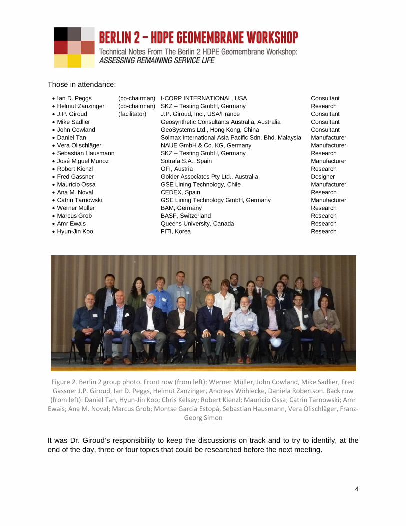
Figure 2. Berlin 2 group photo. Front row (from left): Werner Müller, John Cowland, Mike Sadlier, FredGassner J.P. Giroud, Ian D. Peggs, Helmut Zanzinger, Andreas Wöhlecke, Daniela Robertson. Back row
(from left): Daniel Tan, Hyun-Jin Koo; Chris Kelsey; Robert Kienzl; Mauricio Ossa; Catrin Tarnowski; AmrEwais; Ana M. Noval; Marcus Grob; Montse Garcia Estopá, Sebastian Hausmann, Vera Olischläger, Franz-
Georg Simon
It was Dr. Giroud’s responsibility to keep the discussions on track and to try to identify, at the
end of the day, three or four topics that could be researched before the next meeting.
5
5.0 WORKSHOP INVITATION OUTLINE
Invited participants were sent a skeleton proposed protocol and were requested to prepare andsubmit a 400 word “abstract” of a relevant topic prior to the workshop to stimulate discussion.
The abstracts were circulated to all participants before the workshop.
The day after the INTERNATIONAL GEOSYNTHETICS CONFERENCE in Berlin ends,I-CORP INTERNATIONAL (USA) and SKZ – Testing GmbH (GERMANY) are co-chairing a workshop to develop a protocol for the determination of remaining service lifein in-service exposed HDPE Geomembranes. The objective is to determine when liners
need to be replaced before a catastrophic failure occurs.
Pre-service lifetime estimates based on testing virgin materials at specific temperatures,in specific environments, cannot possibly reproduce all the synergisms that can occur inthe field, but once a material has been in service for some time it should be moreappropriate to assess remaining service life in that continuing environment.
The outline of a remaining service life assessment protocol follows and abstracts/paperswill be invited from about 35 experts modifying that proposal or proposing anotherprotocol. About 15 of these papers will be briefly presented to initiate extensive
discussion. All papers and the discussion will be recorded and published electronically.
The skeleton of a proposed reference protocol is:
Definition of EoL
Measure OIT of exposed surface layer to assess stabilizer remaining
Measure carbonyl index to assess extent of surface oxidation
Measure stress cracking resistance of unnotched specimen or of
melted/solidified plaque
Determination of critical carbonyl index at which SC is initiated
Assess impact of SCR on SC initiation after critical CI is reached
Consider surface properties vs. bulk properties. Consider use of thin film specimens.Consider novel testing techniques - impact resistance, autoclave oxidation, strain-
hardening modulus.
Remember, we are seeking remaining service life of already installed material, not the
expected life of virgin material.
BERLIN 2: One target. Multiple methodologies. Lively discussion.
One commonly heard comment was,
“I have no test results, so I have nothing I can contribute to the discussion”.
Clearly, there are little data available, hence the reason for the Workshop. The objective of thediscussion was to identify the data that are needed. Thus, forward-looking, out-of-the-box
thinking, rather than hard data, was required. Many participants had difficulty with this.

6
6.0 INDIVIDUAL INTRODUCTORY ABSTRACTS
There are several recurring questions that can be followed during the initial presentations and
the subsequent discussion. They are:
Definition(s) of failure in individually measured parameters that individually or togethercan define EoL.
What combination of parameters is required to define EoL?
Monitoring changes in measured parameters and extrapolating them as a function oftime to determine remaining service life, as opposed to taking a sample, measuringrelevant parameters, then performing accelerated aging tests to determine time to EoL.
Perform tests relevant to the service environment of each facility, as opposed to doingstandard tests applicable to all installations.
Focus on tests on past performance of the liner to extrapolate to EoL rather than focuson tests that show the future performance of the liner and time to EoL.
Test seams as well as liner material since most failures occur at seams.
Selected abstracts submitted by the invited experts follow:
6.1 Abstract of Mike Sadlier:
The obvious answer to the EOL question is when it “ceases to perform the required function” butthat can mean different things in different situations. Much of this will depend on what is goingon around a liner. A liner buried under tailings or waste and immobilized may lose properties butcontinue to reasonably perform its required function. However a pond liner or floating cover that
loses properties will quickly cease to function.
The other important question is what HDPE are we talking about? To me there are three verybroad categories of HDPE with distinctly different properties and this brings into question
whether our current definition of HDPE is adequate:
The “old time” HDPE with carbon black and little else had its difficulties with welding and
stress cracking but it brought excellent chemical resistance and excellent UV resistance
as can be seen on some older installations.
The “current standard” HDPE intended to meet GM13 is easier to work with and has
better stress cracking properties along with what seems to be reasonable chemical
resistance and good UV resistance.
The “new world” HDPE that shows much improved mechanical properties (e.g. multiaxial
elongation at over 40%, NCTL approaching 1500 h). With good high-pressure OIT (HP-
OIT) we can anticipate good UV performance but with mechanical properties similar to
linear low-density polyethylene (LLDPE) what do we expect of chemical resistance?
We also need to know more about the real world of exposure of a HDPE or other GMB materialwhich may well involve influences beyond those considered at design. Some examples includeacidic ash from certain coal fired power stations, active radiation and other minerals in thegeneral environment, especially at mining sites. There have been occasions when deterioration

7
due to the intended exposure was minimal but other more general exposures have caused
damage.
In assessing the performance of a GMB in service we are often limited by the capacity to extractsamples from exposed locations and the capacity to generate a “benchmark” for theperformance of unexposed material. Does material sampled from an anchor trench reallyrepresent unexposed material? This is where archived materials and exposure coupons canenable a much better informed answer to the perennial question “how much time do we have
left?”
6.2 Abstract of John Cowland:
The expected life of GMBs will depend on their intended applications, which can be quitedifferent for different projects, such as mining projects, solid waste landfills, the containment ofwater and the containment of hazardous liquids. Expected life can also be affected by exposure
to high and low temperatures, and UV light.
All too often, the design engineer is required to take responsibility for the future performance ofa GMB manufactured with additives that the design engineer knows little about. Indeed, it is myexperience from many factory inspections that some manufacturers do not know as much aboutthe additives they have been sold to add to their GMBs as they should do to safeguard theirown liability. I have experienced unfortunate cases where additives have been used to protect
the GMB against exposure to acids where the project will expose the GMB to alkalis.
The skeleton of the proposed reference protocol is excellent, and in my view the workshop
should also discuss how this protocol can help design engineers.
Finally, in my opinion, this workshop should be expanded to include all types of GMB, not justHDPE, or medium-density polyethylene (MDPE).
6.3 Abstract of Fred Gassner:
In response to the request for an opinion on life of HDPE GMB, I provide the following points
from the point of view of a designer:
The operational or functional life of a GMB is related to when the effect of the GMB is
materially different to what it was intended. It is my opinion this is when the seepage rate
through the liner due to defects has changed by one order of magnitude compared to the
design intent.
In my experience the degradation/failure of GMB liners occurs or starts at welds. A
defect formed due to degradation is usually a long split along the edge of seam of the
GMB and its seepage effect can be assessed similar to a wrinkle. The impact of failures
along weld edges is most marked in ponds, where usually no or minor confinement
exists over the GMB. The consequence of failures along seam edges in landfills may be
less due to the confinement effect on the GMB.

8
Much analysis and research is aimed at intact GMB. Consideration should be given to
the weld conditions and their durability as welding results in degradation of
stabilizers/AO from the welding heating effect and hence is likely to be the first area of
age failure of GMB liners.
Stress cracking can occur while the GMB still has a moderate level of OIT time. Probably
worthwhile to get a better understanding of current stabilizer packages and their effect
on SCR. Some GMBs plateau at certain OIT values, and is possibly linked to mobility of
stabilizers molecules within the GMB sheet. So OIT values may no longer be a reliable
way to assess the degradation status of the GMB.
The remaining service life of an exposed GMB can be assessed by a simple tensile test
on coupons across the welds, compared to strength values achieved referenced from
installation quality control records. These residual strength values can be compared to
design strength requirements for wind uplift etc. Once values drop to unacceptable
factors of safety this liner has reached its end of life, as a design wind effect is likely to
result in large extent of liner seam separation at the panel seams. Failed seams along
panel edges are likely to result in seepage rates similar to no liner being present, in most
situations. This can be assessed on a case by case basis.
With advances in the GMB industry, is there a basis to develop a GMB with most of the
chemical resistance of HDPE but with a resin that is not prone to stress cracking? The
majority of projects do not need the very high chemical resistance of HDPE.
6.4 Abstract of Catrin Tarnowski:
In the recent years the focus on the relevant long-term performance parameter of HDPE GMBshas changed: Whereas for several years the community talked on stress crack resistancenowadays the focus is getting back to oxidative stability. It seems that with having establishedthe performance parameter for NCTL being > 300 h acc. to ASTM D5397, Appendix, that theproblem of early failure is solved. Also considering that GMBs shall be installed in relaxed
conditions, stress cracking should not be an issue.
But just for exposed applications we cannot exclude external stresses like wind action for
example. When failures are reported the failure mechanism is a brittle one – stress cracking.
Thus not only the stage of oxidation, but also the stress crack performance related to thespecific conditions of use has to be considered. The topic – when does a liner need to bereplaced before a catastrophic failure does occur – is just for exposed applications a verychallenging one. So what is the stress crack resistance value needed to overcome possible
stress?
From the authors point of view a protocol addressing critical/relevant points in projects would bea starting point rather than knowing the GMB performance only. This might possibly beleaching, wind speeds, points and number of wind action, critical weld areas or bridging
problems, initial performance of the liner, kind of raw materials used and various others.

9
With such a protocol one might find similarities in different projects related to the aging stage ofa GMB and possible time to failure or necessary point of replacement. Thinking about failureswhich have occurred after short time period only, whereas in other cases HDPE GMBs areexposed for more than 30 years and still in service. Also a database on the properties of these
GMBs itself might be a helpful tool.
6.5 Abstract of Ian Peggs:
Many studies have been done on the expected service life of a given as-manufactured HDPEGMB material in a given environment usually covered by soil. Lifetime is usually presented astime to reduce a given parameter, often tensile strength, to 50% of its original value. This isquite an arbitrary parameter. And most researchers will clarify that the results apply only to thatspecific HDPE formulation in that specific environment. Unfortunately no laboratory testenvironment can reproduce the field environment and synergisms of temperature(expansion/contraction), chemistry (environment/internal), and stresses (expansion/contraction,wind uplift), and UV exposure. And field failures rarely occur as a result of the material losing its
tensile strength.
Most usually it is recognized EoL occurs as a result of thermal oxidation and UV photo-oxidationwhich causes the initiation of stress cracks in the exposed surface which ultimately propagatethrough the GMB by slow crack growth or rapid crack propagation. Since it is not possible topredict the propagation rate of a stress crack through a given thickness of GMB EoL is thereforeconsidered to be when stress cracks first occur in an exposed surface. So, how can we assessthe oxidation "degradation" rate in an exposed GMB, provided of course it will remain in thesame environment? Two or three samples taken after different service times will be comparedto the uninstalled GMB. The following parameters will be measured for the following reasons,
remembering that oxidation is a surface process:
HP-OIT to assess the rate of consumption of anti-oxidants in the stabilizer formulation.
This will be done on a surface layer of the exposed liner, not on the complete thickness
as is usually done.
When the HP-OIT effectively reaches a plateau in the surface layer, oxidation may not
immediately occur. Therefore CI will be measured to determine the extent and rate of
oxidation. The use of an attenuated total reflection (ATR) crystal in a Fourier transform
infrared spectrometer (FTIR) will enable the CI of a surface layer to be measured.
Researchers in HDPE gas pipe have proposed there to be a critical CI at which SC is
initiated. To determine this relationship in the exposed material the surface CI measured
above will be compared to the unnotched SCR of a thin plaque prepared from the full
thickness sample.
This will require data to be generated on the relationship between CI and unnotched
SCR on variably oxidized specimens to determine the critical CI at which SC occurs on
the GMB surface.
Thus the measured CI at different service times can be extrapolated to the time to critical
CI and the initiation of SC, therefore the time to end of practical service life.
10
Knowing the time to EoL should allow the owner to plan for appropriate repairs or replacement
of the liner and to avoid an unexpected catastrophic failure.
6.6 Abstract of Werner Müller:
The remaining service life of exposed HDPE GMBs depends (1) on the type and amount of
AOs, which are still present, (2) on the loading conditions, i.e. to which extent tensile forces are
regularly imposed onto the GMB due to thermal shrinkage at low temperatures, wind suction,
deformations, indentations, etc., (3) the surface properties, i.e. occurrence of critical stress
initiation points, deep scratches and grooves, local stress concentration at geometric
discontinuities associated with seems, etc. Typically HDPEs are stabilized by a combination of
phenolic and phosphitic AO. These AOs are primarily consumed by UV accelerated oxidation
processes and hydrolytic degradation at the surface, by extraction and evaporation of the AO
molecules and their degradation fragments from the surface. This will be discussed in detail.
Two regimes of AO depletion have been found. Regime A: Accelerated loss of AOs due to
exudation. Regime B: loss by normal diffusion. Since the AOs get lost at the surface, there is a
concentration gradient between surface and bulk which drives the diffusion of AOs from the bulk
to the surface. If AO concentration in the bulk becomes very low and concentration at the
surface is therefore essentially zero, then a heterogeneous oxidation process starts at various
spots on the surface, which are depleted from AOs (regime C). With tensile force present,
cracks are initiated at these spots. Failure of the whole product will then be imminent. The depth
profile of such AO concentration can be measured by OIT. From such measurements, one may
deduce remaining service life. Nowadays, hindered amine stabilizers (HAS) are sometimes
added to the “classical” stabilization. Since HAS are less extractable and not sensitive to
hydrolysis, HAS may still be present even after extended loss of phenolic and phosphitic AO
components. However, HAS do not prevent oxidation, even though, oxidative degradation is
significantly decelerated. What happens to HAS stabilized HDPE GMBs? To which extend is
stress cracking initiation prevented? How can a depth profile of HAS be determined, since
neither Std-OIT nor HP-OIT are applicable?
6.7 Abstract of Amr Ewais:
There are a number of challenges to creating a protocol for assessing the remaining service life
of exposed GMBs. First, it is anticipated that the GMB resistance required will differ from one
application to another. Second, the rate degradation of the GMB would not only depend on the
GMB properties (resin) but also on the exposure conditions. Third, there are difficulties
associated with the techniques used to assess the remaining resistance of a GMB. For

11
example, one of the techniques used to assess the GMB resistance is the stress crack
resistance (SCR, ASTM D5397) of the GMB. To use the SCR to assess the end of life for the
GMB, the following questions need to be answered: (a) is this a useful technique, and (b) if so,
what is the critical SCR at which the liner will rupture and when will this critical SCR will be
reached? To address these questions, two studies were conducted to investigate the
degradation of polyethylene GMBs under different loading conditions (demand). The first study,
considered the degradation of different GMBs exposed to very different climatological
conditions. It was shown that: (a) SCR may decrease significantly without any evidence of
chemical degradation, and (b) the GMB installed on a 3H:1V, 22 m high, slope had not ruptured
after 16 years despite a reduction in SCR to about 70 hours. In the second study, three sets of
polyethylene GMB samples (14 different polyethylene GMB) were left exposed on a wooden
rack inclined at 2H:1V in southern Ontario Canada. The first set of the GMB samples were
exhumed from leachate lagoon after 14 years in service before being placed on the rack for an
additional 17 years (a total of 31 years aging to date). The second set of GMB samples were
taken from an initially un-aged GMB and have been exposed since 1997. The third set of GMB
samples were taken from 12 different polyethylene GMBs of different thicknesses and resins
and have been exposed since 2010. The temperature of the GMBs from different sets was
monitored and it was found that: (a) there was no significant difference in the temperatures of
the black GMBs regardless the difference in resin and thickness, (b) in Kingston, Canada, the
temperature of the black GMB may exceed 70 °C in the summer where the temperature of the
white GMB did not exceed 40 °C, and (c) minimum temperature of the GMB in winter may reach
-20 °C. Although the GMB (from which the samples of the first set was taken) extensively
ruptured in the lagoon during 14 years of service; intact samples taken from the lagoon and
aged on the roof were observed to rupture after 12 years exposure on the roof (26 years of
aging in total for these samples). This highlights the role of load-demand on the rupture of the
GMB. Although the GMB samples in the second set still have a standard OIT (Std-OIT) of ~40
minutes (30% of the initial value) and a HP-OIT of 1200 minutes after being exposed to the
elements for 16 years, several severe surface cracks have developed and the stress crack
resistance has decreased from ~ 6000 hours to ~ 3000 hours (possibly due to surface aging).
Comparing the depletion of the Std-OIT from the GMBs of third set in the second study, it was
found that: (a) an increased HP-OIT correlated with a decreased depletion of Std-OIT, (b)
thicker GMBs had slower Std-OIT depletion, (c) the depletion of AOs from high density and
linear low density polyethylene GMBs depended more on the AO package than the polyethylene
resin, and (d) the white GMB had the slowest Std-OIT depletion. The SCR measured for the
black GMBs in the third set of samples decreased by 30 to 70% although they still had
significant Std-OIT and HP-OIT; in contrast, the stress crack resistance of the white GMB has
not decreased over three years of monitoring this GMB. The results of these studies highlight
the challenges of assessing the EOL of a GMB and the need to better understand the different
factors that may affect the time to GMB rupture.
12
6.8 Overview
Few participants addressed the immediate topic of developing an integrated testing protocol toassess remaining service life. Several addressed the need for durability in specific applicationsand several addressed different individual test methods that might be used as a part of anoverall protocol but few addressed the integration of a number of tests. For instance, stresscrack resistance test methods, and the data they generated were discussed but there was nodiscussion on how these data would or could be used to define a remaining service life.Nevertheless, it was interesting to see how the various experts interpreted the topic and thedepth of their knowledge of HDPE GMBs.
7.0 MORNING DISCUSSION SESSION
7.1 Ian Peggs: General introduction
In his general introduction to the workshop, Ian Peggs identified what he expected would besome of the more lively topics of discussion. These included:
Confirming the “natural” mode of failure of an exposed HDPE geomembrane at the endof its service life, assuming no negative mechanical, physical, and chemical agencieswere acting upon it.
How to describe a practical EoL so that the “natural” mode of failure does not occur. Identify parameters and test methods that allow for a practical EoL to be determined. Giving owners and engineers confidence that a geomembrane’s end of life is
approaching, but that there is still has time to repair/replace the liner so that failure doesnot occur.
Identify research that is needed to provide data that is presently not available todetermine EoL.
7.2 Mike Sadlier asked:“What is the function of a GMB in a specific project and how is the GMB used?” EoL could
be seen as “end of function”. In most projects it is difficult to cut large samples. Only small
samples can be taken. On these samples only OIT measurements can be made. Therefore
tensile tests and NCTL tests are not done. It is difficult to find archived samples (baseline
samples). Such samples should be stored in a controlled climate without stress and unaged.
Samples from anchor trenches are often used as the best baseline samples available in a
project. Old and new HDPE GMBs have different formulations. New HDPE GMBs have
‘enhanced’ performances. OIT or HP-OIT is not always appropriate. The exposure of a GMB
can be very different. The GMB can be exposed to UV or to chemicals. Even at the same
site a GMB may have different locations with other exposures.
7.3 John Cowland mentioned, that
… different project owners tolerate and accept differential leakage rates. For prevention of
water ingress into an earthen dam suffering piping problems, zero leakage might be insisted

13
upon. For solid waste landfills with double GMB layers, the leakage rates resulting from up
to 15 defects per hectare in one layer might be accepted. How can an all-encompassing
EoL be defined if some projects can tolerate more leakage then others?"
GMB in floating covers for wastewater are designed to withstand mechanical stresses at the
anchor trenches. Various (hazardous) chemicals (cyanide and caustic soda in gold mining,
sulphuric acid in copper and nickel mining, caustic soda in processing of alumina) are used
in the mining industry and operating temperature has been increased from 30°C to 60°C in
some mines. Laboratory tests are often carried out at 20°C but in mining projects the
temperatures are higher! Scratches on the surfaces of a GMB can reduce service life.
Joints and connections of GMB to rigid structures can overstress a GMB.
Testing protocol is needed to be tailored to the function of the GMB containment.
7.4 Daniel Tan stated, that
… most studies are made with GMB with thicknesses of 1 mm and thicker. Thin GMB with
thicknesses of 0.5 mm and 0.75 mm are not studied regarding durability. There is a need for
research on thin GMBs. The highest depletion of stabilizers (in other words: lowest
remaining OIT) is at the crest. The AO depletion rate is significantly higher for thin GMBs.
The increase is exponential. In tropical areas the washing off of dust accelerates the aging
of GMB compared with arid regions. Dust can act as a protector of a GMB against UV-aging.
Periodical testing of OIT, HP-OIT, tensile properties and SCR at facilities across the world is
recommended.
7.5 Vera Olischläger noticed, that
… the meaning of the thickness for the lifetime of GMB shall be studied. Research is
needed for GMB thicker than 1.5 mm.
7.6 Sebastian Hausmann proposed, that
EoL of exposed GMB could be defined as the time when mechanical properties start to
change, when OIT is ‘zero’ or in high-pressure autoclave test (HPAT) at the onset of oxygen
pressure decrease – in other words, when the polymer starts to degrade.
7.7 Helmut Zanzinger required, that
…for the evaluation of the surficial aging of exposed GMBs, the unexposed GMB surface
shall be notched in notched constant tensile load (NCTL) tests or in accelerated NCTL
(ANCTL) tests. Failure times at different stresses, other than 30% of yield stress, should be
determined in NCTL tests. NCTL tests at temperatures other than 50°C would be of interest.
In a certain depth of a GMB stabilizers are not completely consumed as it could be the case
at the exposed surface. Inside the GMB the polymer could still be protected from aging and

14
the original reference curves of SCR tests are kept valid for the deeper section in the
exposed GMB.
7.8 Jose Munoz informed, that
… the SCR of HDPE GMB is good for resins with low density and wide molecular weight
distribution.
7.9 Robert Kienzl observed, that
... cracks occur preferably near extrusion welds. They are found after 15 to 25 years in
service on GMB installed in the late 1980s. Three-mm-thick HDPE concrete protection liners
(CPL) showed no failures after 10 years in service as containment of landfill waste water.
7.10 Fred Gassner believes, that
… EoL depends on the functional intent of the liner. He experienced long cracks next to
weld due to heating effects. SC may occur due to wind load and thermal cycling effects
above water line in ponds but pond may still function to hold liquid. There are stress
concentrations by seams. Therefore, research on SCR of seams is necessary.
Editor’s Note: Later on it became clear that other design engineers made the experience
that is often very difficult taking even small samples from the side or it is not even allowed by
the owner to take any sample, because it is the client’s desire to keep the facility
operational. And exposure coupons are much rarer than they should be in the real world.
7.11 Mauricio Ossa found, that
… white surface of a GMB reduces the temperature differential to minimize wrinkles and AO
depletion of white GMBs is lower than of black GMBs.
7.12 Anna M. Noval showed, that
… the performance of a 1.5 mm thick HDPE GMB in San Isidro reservoir, Gran Canary
Island, has been shown for water tightness after 22 years – even when OIT decreases, CI
increases and the retained mechanical properties are around 70 to 75% of the original
mechanical properties.
7.13 Catrin Tarnowski realized, that
… there are different perspectives and challenges of project owners, designers,
manufacturers and installers. Different protocols are needed for different
formulations/products and for different applications/projects and for different aging and for
different installations. Which information on the formulation can be made available? Which
are the relevant properties (OIT, NCTL, carbonyl index (CI), performance of welds) to be
monitored? Are the current test procedures adequate? These tests should focus on
15
remaining service life. Should we do tensile creep tests, stress relaxation tests and the old
impact strength tests? Is there information available on the product in its initial stage?
Such information should be stored together with retained samples for future projects. We
have to define the needed relevant information for future evaluations of exposed GMBs.
Such application related information includes:
external forces at critical point of the application amount of UV-radiation average temperature and peak temperature bearing layer influence chemical influence leaching by contained water or rain wind actions or even uplift in connection with lying flat quality of welding works points of possible stress concentrations of the above AND: Can samples be retrieved at critical areas?
The best practice (design, product, installation, quality control / quality assurance (QC/QA)
and allowance for monitoring) for an exposed application of a GMB should be described and
respected by all involved parties of a project.
7.14 Ian Peggs remarks, that
… SC occurs after a certain degree of oxidation. The major concern is on bulk performance
vs. surface performance. The OIT is to be measured on the surface, but how thick is the
“surface” to be tested? The SCR notch must not penetrate the surface layer. Should SCR
tests be made on un-notched specimens? Could trial tests be made on thin films? Most
failures occur as a result of SC at extrusion seams. A simple approach for EoL would be a
first appearance of stress cracks.
7.15 Werner Müller stated, that
… exposed GMBs are always affected by some kind of mechanical stress. Exposed GMBs
will fail in the long run by stress cracking primarily located at seams. Ductile failure always
indicates errors in design or installation or it may be triggered by accidents or disasters.
Oxidative degradation will strongly reduce SCR. Even high SCR GMBs will finally become
susceptible to SC triggered by oxidative degradation. A protocol has to refer to the state of
oxidative degradation. The lifetimes of buried GMBs are very long as AO depletion process
is extremely slow. Exposed GMBs degrade faster due to UV-radiation and additionally by
the input of solar heat radiation primarily in a small surface layer. Oxidation starts at
“oxidation spots” in the surface. SC are initiated at those spots. Once initiated they will
propagate through the intact bulk material within years (depending in field site conditions).
OIT over thickness should be measured. Survey of any indication of crack formation at

16
seams is necessary. An evaluation of the change of the SCR is needed by determining the
whole curve. Get also the information about type and amount of AO, measure the Std-OIT
profiles through the thickness of the GMB and evaluate these profiles.
7.16 Marcus Grob noted, that
… OIT and even HP-OIT measurements are far away from real thermal stresses on GMBs.
OIT is measured in the liquid/molten state but the final application is in the solid state. In a
molten state thermal/processing history has been cancelled, mobility of the stabilizers is
much too high, solubility of the stabilizers strongly influenced by the temperature, volatility of
the stabilizers is different, inhomogeneity of the stabilizers in the polymer (crystalline
regions/amorphous regions) are not considered and reactions in a solid phase or in a highly
viscous liquid with a gas depend on the diffusion of the gas/partial pressure of the gas. OIT
depends strongly on the sample preparation, surface to volume ratio. Different stabilizers
show different activity at the OIT testing temperatures. OIT depends not only from the
polymer and the stabilizers but also on the rest of the formulation (fillers, pigments,
antacids), but reactivity is not linear at the end-use conditions and at OIT temperature.
Failure criterion for HAS or for phenol could create completely different EoL. Accelerated
aging should be done under similar conditions as the final application (e.g. extractive, light
exposed), with the same concentration as in the final application, at not too elevated
temperatures to have similar degradation patterns, with a well-defined EoL criterion and the
disadvantage is: It is time consuming.
7.17 Amr Ewais reported, that
…50% retained strength and 50% retained elongation are not the appropriate failure
criterion for an exposed GMB. The presence of high OIT values does not necessary mean
that the GMB is resistant against chemical oxidative degradation. The surface of a GMB
may degrade before the core increasing the susceptibility of the GMB to SC. GMB
resistance is significantly affected by the morphological changes that take place in the GMB
decreasing its SCR before AO depletion or chemical degradation has occurred.
7.18 Overview
It very quickly became apparent that the definition of a single EoL would be very difficult if
not impossible. A general definition such as “when the GMB ceases to perform its design
function” moves us no further forward. Since the function of the liner is containment, one
could argue that the first appearance of a leak is EoL. However, leaks can be repaired and
allowable leakage rates (ALR) are specified in several projects to accommodate some
leakage that will not further damage the subgrade or the lining system.
One could argue that the first appearance of a stress crack (the mode of ultimate failure) on
an exposed slope could be EoL. But cracks on a slope do not mean there are cracks under
the liquid level that are leaking.

17
When the leakage rate reaches the ALR could also be considered the EoL, but repairs can
be made to extend service life. However, if repairs do not reduce leakage below the ALR,
that too could be defined as EoL.
To further complicate the issue, most liner failures are initiated at seams that have been
overheated, suffered overgrind, or were improperly applied, and which have little to do with
the degradation rate of the GMB material itself.
It therefore appears that EoL could consist of two components. The basic component would
be for liner material degradation processes and based on first cracking, first in-service leak,
critical OIT, etc. The second component would be a modification for the specific application
of the liner and seaming quality, etc.
To counter the complexity of a definition of EoL it was expected that if the physical-chemical
environment did not significantly change while the liner was in service, it would not matter,
for instance, what the relative contributions of chemistry, temperature, and UV exposure
would be to the oxidation degradation rate, all that would be required would be a measure of
the extent of oxidation. Thus, there would be no need for complex considerations of
environmental parameters. Detailed knowledge of the make-up of the environment would
not be necessary.
8.0 SUMMARY OF MORNING SESSION
The morning session concluded with the identification of the major topics of concern which wereto be addressed in the afternoon. As identified by JP Giroud and Chris Kelsey, they were:
8.1 Definition of EoL
The morning session of Berlin 2 was dedicated to 17 presentations by workshop participants
and a brief session focused on defining EoL and outlining goals for remaining discussion in
the day. The DEFINITION AGREED UPON, for the sake of guiding the day’s continuing
conversation, was: “End of Life is when a GMB is no longer acceptable for its intended fluid
containment function as a result of degradation.“
ISO/PDTS 13434 describes EoL in the following:
A geosynthetic is intended to perform a particular function for a minimum expected time,called the design life. Impermeability to liquids is the functional property for a geosynthetic
barrier.
Assessment of the durability of structures using geosynthetics requires a study of theeffects of time on the functional properties. The physical structure of the geosynthetic, thenature of the polymer used, the manufacturing process, the physical and chemicalenvironment, the conditions of storage and installation, and the load supported by the

18
GSY are all parameters which govern the durability. The main task is to understand andassess the evolution of the functional properties over the entire design life. This problem isquite complex due to the combination and interaction of numerous parameters present in
the soil environment and the lack of well documented experience.
It is necessary to differentiate between the available and required values of a functionalproperty. Figure 3 is a schematic representation of the evolution of the available property of a
material as a function of lifetime, represented by the curves on the graph. The functionalproperty may be a mechanical or a hydraulic property such as tensile strength or permeability.The events that happen between manufacture of the product and the end of product life can beindicated along the time axis. After installation, the operating life of the material starts. Failure
implies that the geosynthetic can no longer perform the function for which it is being selected.
Figure 3. Functional property of an exposed GMB as a function of time (Courtesy: JP Giroud)
ST: Tensile stress in storage and transportationC: Tensile stress during constructionAS: Actual tensile stress in service without windMS: Margin of safetyW1: Wind less strong than design windW2: Unforeseen strong wind causing rupture and repair of the
geomembraneW3: Unforeseen strong wind causing premature end of service
because the geomembrane is not repairableCD: Construction damageED: End of design lifeES: End of service lifeEG1, EG2, EG3: End of GMB life (defined by criteria)
19
Editor’s note: As a definition for EoL could not be agreed during the workshop thediscussion among the design engineers continued and ended in Figure 3 (above)being developed by JP Giroud in March 2018. It became obvious that we have todistinguish between end of design life, end of service life and end of product life.The later one is project specific and depends and the criteria applied, becausesome projects may tolerate more leakage than others.
Prediction for EoL is described by Greenwood et al. (2012):
EoL prediction can be based on experience, on the extrapolation of measured properties,or on tests intended to simulate the whole lifetime of a GSY by accelerated testing.Experience is simply not available for the long design life expected of GSY.Measurements have to be made for at least ten to twenty years in order to detect withsufficient accuracy the changes that will lead to failure after more than a century. Manyprocesses occur non-linearly, showing little evidence of change in their early stages andthen reaching a threshold where degradation sets in emphatically. In others one processof degradation follows another. Life prediction is not as simple as measuring theprogressive wear of a car tire to determine when it will need replacement.
"End of life” is a more appropriate description than failure. EoL depends on the function for
which the geosynthetic has been chosen. The function determines the end of life.
To make a numerical life prediction, the end of life has to be defined as a number. Vaguegeneral statements are not sufficient. Examples of a quantitative and measurable criterionare as follows:- 50% reduction in strength,- increase (e.g., 10%) in permeability,- visible holes in a GMB, whether the GMB is a single or double liner or a composite, inwhich case the quality of contact between the GMB and the underlying mineral liner has tobe considered or whether the leachate source is persistent, leachate head, and the
chemical nature of the leachate and the sensitivity of the site to groundwater quality.
Thus the end of life criterion can vary from one site to the next. Lifetime of a geosynthetic,as defined by its end of life criterion, is greater than its design life. In other words, the
geosynthetic will continue to do its job.
8.2 Prediction of remaining service life on the basis of control or reference samples
The use of control samples is a GOOD SOLUTION, but control samples from the identical batch
are hardly available.

20
The use of unexposed samples from the same site as reference samples is the SIMPELESTSOLUTION but it has many uncertainties:
- Samples from a weld are very small.
- Samples from an anchor trench might be damaged during installation.
- Often only OIT can be determined, but mechanical properties would be interesting.- “Unexposed” samples from a site are also aged to a certain extent.
Figure 4. Prediction of EoL based on “unaged” control samples
Evaluation should be better based on two ways:
Periodic short-term tests on samples from the site in a monitoring program.
This is the best way to predict the remaining service life.
The second best solution might be accelerated tests in the laboratory on samples from
the site, to determine the remaining service life for which a modeling for lifetime
prediction is necessary. (NOTE: Not all attendees are in agreement about the utility of
accelerating testing for creating an EoL protocol.)
21
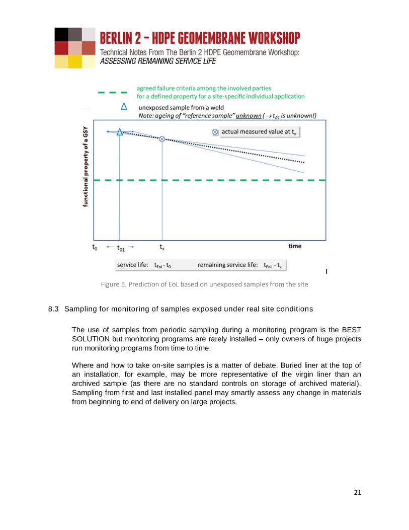
Figure 5. Prediction of EoL based on unexposed samples from the site
8.3 Sampling for monitoring of samples exposed under real site conditions
The use of samples from periodic sampling during a monitoring program is the BESTSOLUTION but monitoring programs are rarely installed – only owners of huge projectsrun monitoring programs from time to time.
Where and how to take on-site samples is a matter of debate. Buried liner at the top ofan installation, for example, may be more representative of the virgin liner than anarchived sample (as there are no standard controls on storage of archived material).Sampling from first and last installed panel may smartly assess any change in materialsfrom beginning to end of delivery on large projects.
22
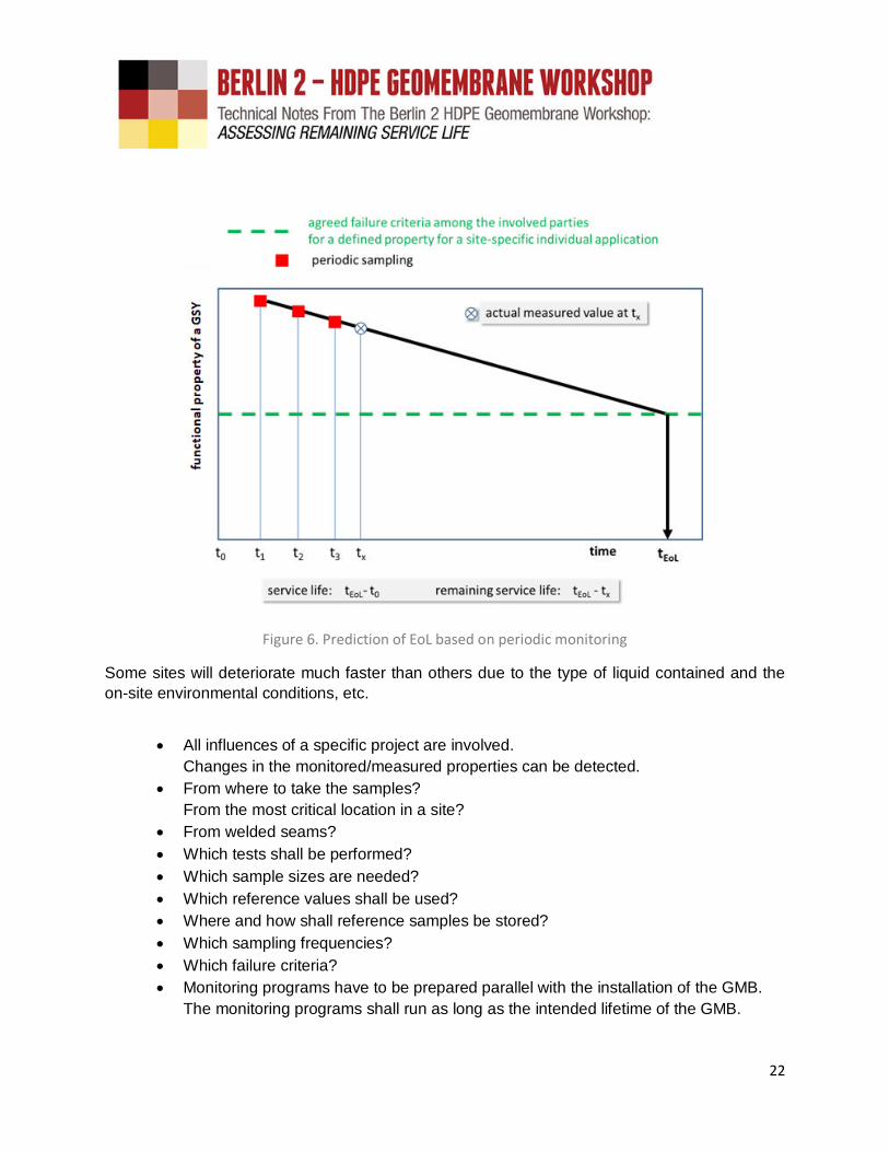
Figure 6. Prediction of EoL based on periodic monitoring
Some sites will deteriorate much faster than others due to the type of liquid contained and the
on-site environmental conditions, etc.
All influences of a specific project are involved.
Changes in the monitored/measured properties can be detected.
From where to take the samples?
From the most critical location in a site?
From welded seams?
Which tests shall be performed?
Which sample sizes are needed?
Which reference values shall be used?
Where and how shall reference samples be stored?
Which sampling frequencies?
Which failure criteria?
Monitoring programs have to be prepared parallel with the installation of the GMB.
The monitoring programs shall run as long as the intended lifetime of the GMB.

23
8.4 Simulation of remaining service life using accelerated aging tests
IF neither control samples nor “unexposed site samples” nor “periodic samples” areavailable, accelerated tests in the lab on samples from the field might be considered foruse as an ALTERNATIVE SOLUTION to EoL prediction.
Figure 7. Prediction of EoL based on accelerated tests in the lab
However, workshop participants were not in agreement on whether this would bepractical. Consider: Should an accelerated aging test be conducted on a 20-year-oldliner still in service? More discussion is needed here, but laboratory work in this area isworth visiting.
As such, IF aging tests shall be performed, they should be performed under definedaccelerated conditions with the real media from the specific project simulating singularaging processes or simulating combinations of different aging tests one after the other.The test parameters for each single aging test must to be considered and the projectspecifically defined.
24
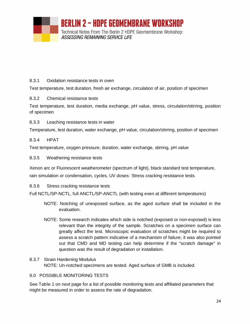
8.3.1 Oxidation resistance tests in oven
Test temperature, test duration, fresh air exchange, circulation of air, position of specimen
8.3.2 Chemical resistance tests
Test temperature, test duration, media exchange, pH value, stress, circulation/stirring, position
of specimen
8.3.3 Leaching resistance tests in water
Temperature, test duration, water exchange, pH value, circulation/stirring, position of specimen
8.3.4 HPAT
Test temperature, oxygen pressure, duration, water exchange, stirring, pH value
8.3.5 Weathering resistance tests
Xenon arc or Fluorescent weatherometer (spectrum of light), black standard test temperature,
rain simulation or condensation, cycles, UV doses: Stress cracking resistance tests
8.3.6 Stress cracking resistance tests
Full NCTL/SP-NCTL, full ANCTL/SP-ANCTL (with testing even at different temperatures)
NOTE: Notching of unexposed surface, as the aged surface shall be included in the
evaluation.
NOTE: Some research indicates which side is notched (exposed or non-exposed) is less
relevant than the integrity of the sample. Scratches on a specimen surface can
greatly affect the test. Microscopic evaluation of scratches might be required to
assess a scratch pattern indicative of a mechanism of failure; it was also pointed
out that CMD and MD testing can help determine if the “scratch damage” in
question was the result of degradation or installation.
8.3.7 Strain Hardening Modulus
NOTE: Un-notched specimens are tested. Aged surface of GMB is included.
9.0 POSSIBLE MONITORING TESTS
See Table 1 on next page for a list of possible monitoring tests and affiliated parameters that
might be measured in order to assess the rate of degradation.

25
Table 1. Parameters that might be measured in order to assess the rate of degradation
TEST STANDARD REMARKS
Tensile Test ISO 527-3
Yield tensile stress and elongation at yield
Tensile strength at break and elongation at break
A “design tensile strength” Td has to be given in kN/m (force per
unit width). Thickness is involved in this consideration, if it is given
in kN/m. The thickness of the tested specimen will not be
measured. The width of the specimen has to be measured. The
basis must be tensile strength at yield for HDPE GMB. Evaluation
is based on tensile strength T vs. time (logarithmic scale) log t.
What is the tensile stress in kN/m which a GMB can withstand –
ignoring whether it is textured or smooth, new or already single-
sided partly oxidized?
Std. OIT at temperatures of 180°C
and at 210°C, and HP-OIT at 150°C
ISO 11357-6,
ASTM D3895 and
ASTM D5885
OIT distribution profile through the geomembrane thickness:
- at the exposed surfaces (e.g. upper 300 µm) of the sample?
- at the center of the sample?
- from the entire cross section of the sample?
Oxidation onset temperature (OOT) ISO 11357-6
Stabilizer content
(e.g. HPLC, UV/IR-spectroscopy)
Strain hardening modulus prEN 17096:2017
Recent research has shown a relationship between the strain
hardening modulus determined by uniaxial tensile testing and the
SCR of the materials.
Carbonyl Index (CI) ASTM E334In plastic pipe, it has been proposed that a CI ≥ 0.10 is the
threshold for SC to be initiated.
Multiaxial tensile test (burst test)
EN 14151,
DIN 61551,
ASTM D5617
Water tightness EN 14150
Tensile strength of welded seamDVS 2226-2 and
DVS 2226-3
Shear elongation (DVS 2226-2) and peel separation (DVS 2226-3)
Burst strength and elongation of
welded seamDIN 61551
Impact strength of welded seam ISO 8256
Impact strength tests can provide much information on the
presence of mechanical defects in seams and sheets and their
influence on the susceptibility to stress cracking failures, both
slow crack growth (SCG) and rapid crack propagation (RCP).
Puncture impact energy EN 12691
26
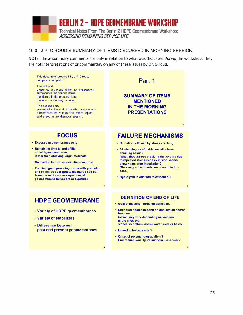
10.0 J.P. GIROUD’S SUMMARY OF ITEMS DISCUSSED IN MORNING SESSION
NOTE: These summary comments are only in relation to what was discussed during the workshop. They
are not interpretations of or commentary on any of these issues by Dr. Giroud.

27

28
11.0 AFTERNOON DISCUSSION SESSION
The afternoon session focused on the question raised in the summary of J.P. Giroud. Muchinformation is needed to ensure a GMB has optimum performance. Research work to be done
was described.
11.1 Liner integrity
A lot of information is needed for a good design of a GMB in any application.
Raw material
Additive formulation
Manufacturing of GMB
Factory Production Control (FPC)
Third party control
Design:
o Installation
o Storage
o Loads (confining pressure, wind loads, thermal stresses, …)
o Environment (UV-radiation, chemicals, …)
o Ambient temperature
o Liner Temperature
o Surrounding soil (particle size, angularity, …)
o Protection of GMB (e.g. use of GTX or sand layers)
o Welding (welding standards, techniques, …)
o Anchorage
o Ballasting
Construction Quality Control (CQC)
Construction Quality Assurance (CQA)
29
As previously stated, many experts felt that samples of the aged liner should be incubated foraccelerated aging tests in order to predict remaining service life. However, as stated in Dr.
Giroud’s summary:
“……. incubation is irrelevant today because we focus on samples taken from the field.”
In other words, we focus on the past real world performance and extrapolate to the future andEoL. The intent is not to perform complex incubation and aging prediction tests to determinefuture degradation rates. EoL is determined by historical performance rather than by laboratory
aging tests.”
11.2 End of Life
Only a broad definition of EoL was reached. EoL occurs when the GMB fails to perform itsrequired function. However, there was no agreement on what constitutes a “failure” to perform.It was felt there is no single definition based on technical performance that could be applied toany lining system. There was a strong feeling that any definition should consider the structuralfunctions of the site-specific geomembrane and the criticality of the installation. For instance, thecontribution of surface texture to stability of the liner on slopes is a factor that impacts the
geomembrane’s EoL.
Several people believe the definition of EoL should be based on “ideal” conditions, i.e. idealdesign and ideal installation, which, of course, rarely happens. Others believe that in the realworld it should be possible to find appropriate parameters that monitor material changes andthat can be combined in some way to track the overall degradation rate independently of quality
of installation and specific environmental conditions.
The difficulty in settling upon a definition of failure for the field can be seen in one of theexample definitions provided to the workshop. It comes from a real litigation case in which the
Final Judgment document cited the following:
“Failure is a condition or state that prevents the liner from fulfilling its intended purpose.Failure of the lining therefore refers to a leak that permits process liquids to contact a
concrete tank (in this case) in significant quantities”.
From the perspective of End of Life and the mechanisms involved in the deterioration and(potential) failure of an exposed HDPE geomembrane, we can immediately observe that thisactual “definition” of failure from a real legal document does not consider any aging or use of thegeomembrane. It does not consider any “ideal” conditions. Rather, it is entirely focused onleakage—which could be present at the inception of an installation (e.g., design, installation, oroperation conditions that are not ideal). Also, how do we interpret “significant” quantities?Certainly, it is useful word: significant means in quantities that have such an impact on theconsidered project that service is interrupted. Still, this definition is far too inexact to move thefield towards a useful EoL definition.

30
11.3 Testing
The tests considered relevant for assessing time to EoL include SCR (possibly un-notchedspecimens), OIT including stabilizer profiles through the thickness of the liner, HP-OIT whenHAS are in the stabilizer package, and carbonyl index (CI). However, applicability of CI wasseriously questioned. This may be because it is a surface layer property while most other tests
are full thickness properties - but a surface layer property may be what we need most.
Regarding SCR, un-notched specimen tests seem to be very important here. Yet, a test with aspecimen notched on the non-exposed side may be useful—if failure occurs from the exposed
face. Such an occurrence would indicate that the exposed face is in critical condition.
If the end of life is to be characterized by onset of stress cracking, the test specimen must notbe notched on the exposed side. Test with an un-notched specimen must be run. A test with aspecimen notched on the non-exposed side may be useful if failure occurs from the exposed
face: this would indicate that the exposed face is in critical condition.
Standard mechanical tests are relevant, but can require large samples (e.g. multiaxial tensiletests). The question of the introduction of impact testing that can reflect surface conditions and
such as has been used to introduce and study RCP cracks in HDPE pipe was raised.
Further physical tests of interest are melt flow rate (MFR), density, and discoloration. Basicphysical characteristics that should be reported to describe the GMB are thickness, additives
and whether the material is smooth, textured, or structured.
11.4 Sampling Frequency
A constant frequency of monitoring such as every 5 years for “ordinary” projects and every 2
years for critical containment projects was suggested.
11.5 Sampling Location
Tests could be performed on samples from all relevant locations such as on slopes above andbelow liquid level, at the waterline, at the crest of slopes, on the floor, and at the anchor trench.However, this is not a research program. Therefore, samples should be removed from what is
considered to be the most aggressive environment location. Welds must be included.
If as-manufactured archive samples have not been retained and maintained in a cool, darklocation the best baseline sample would be from the anchor trench, bearing in mind thatinstallation damage can negatively influence parameters such as impact resistance and tensile
elongation at break.
31
12.0 OVERALL RESEARCH WORK TO BE DONE
Topics and areas of general research required to provide data to help development of a protocol
to determine EoL are as follows:
Is the 3-stage model relevant for exposed GMB?
If we agree that onset of cracking is the criterion, then 2-stage model is right.
Lifetime of GMB in mining
o High temperatures (up to 60°C)o Aggressive chemicals:
- Cyanide and caustic soda- Sulphuric acid
Relevance of thickness of a GMB on durability
(need of research on the service life of GMB with various thicknesses)
o In which condition can a thicker GMB compensate the oxidation in the surface?Is the AO package of a thinner GMB (≤ 1.5 mm) consumed earlier than the identical AO package and concentration of a thicker GMB (> 2 mm)? (For the applications citedin the workshop’s discussions and the sensitivity of EoL in these applications, it’s likelythat geomembranes < 1.5 mm are not relevant to this EoL protocol and not to beencouraged in these applications.)
o Will SC in a thicker GMB occur later than in a thin GMB?o Can a thicker GMB withstand higher external loads than thinner GMB?o What is the minimum thickness of a GMB for a specific application?o Does the thickness represent a “factor of safety”?o Can a thicker GMB compensate mistakes in the installation better?o Can scratches in a thicker GMB be tolerated rather than scratches in a thin GMB?o Do thicker GMBs provide a wider “temperature window” for welding?o Is the welding of thicker GMBs easier?o Do thin GMBs have to be welded in a factory to panels and only thick GMBs can be
welded on site?What are the relevant tests for the evaluation of EoL? And how is EoL to be defined?
Lifetime of welded seams
o Cyclic loading of GMB to simulate wind loads?o Tensile creep?o Stress relaxation?o Impact strength?o SCR of seams?
Accelerated aging tests—if they are to be considered—on samples from the field:
o under similar conditions as in the field (e.g. extractive media, light exposed …)o with the same concentration as in the fieldo at not too elevated temperatures, to have similar degradation patternso with a well-defined EoL criterion

32
Evaluation of GMB based on OIT-measurements:
o From where should a specimen be taken from a sample?o How shall the specimen be prepared?o Check OIT profile over thickness.o OIT can give only an indication but for many AO the OIT test temperature are
unrealistic and then the OIT measurement may be irrelevant.Where are the critical locations to be monitored?
o Near extrusion welds?o Near overheated areas?
Which test data are necessary for the evaluation?
o Full NCTL curve?o NCTL curve for different temperatures?o Notching of the aged side of the GMB or the opposite side?
Data base from periodically testing at facilities across the world
Development of function-tailored testing protocols
Service life of joints between GMB and rigid structures (concrete, metal and plastics)
Effects of colored GMB on temperature in the GMB
(thermo-oxidative aging, thermal expansion effects)
Relevance of density to SCR
Development of failure criteria for phenol stabilized GMB
o Phenol stabilized materials show no change in strength or elongation for a long time
and then mechanical properties drop rapidly.
Development of a failure criteria for HAS-stabilized GMB
o HAS show a steady loss in strength or elongation.
13.0 J.P. GIROUD’S SUMMARY OF ITEMS DISCUSSED IN AFTERNOON SESSION
NOTE: These summary comments are only in relation to what was discussed during the workshop. They
are not interpretations of or commentary on any of these issues by Dr. Giroud.

33
14.0 SPECIFIC ACTION ITEMS
At the end of the day the four topics that clearly needed additional work and discussion were as
follows as agreed by all attendees:
Better definition(s) of End of Life. Can there be one overarching definition but with
secondary definitions depending on application, if necessary? Without question, the fieldneeds something other than “half-life” to work with.
34
Comparisons of bulk OIT and surface layer OIT (or distribution of OIT from one surface
to the other).
Relevance of OIT, CI and impact testing to determination of EoL.
Stress cracking resistance and location of notch, or whether to notch
It is hoped that all participants, and others in the field, will continue to consider these items and
to include them in research projects and in forensic investigations.
15.0 WORKSHOP SUMMARY
A one-day workshop of international experts was held on 26 September 2014, in Berlin,Germany to discuss the development of a protocol to determine the End of Life (e.g., theremaining service life) of an already installed HDPE GMB liner. These technical notes provide
an overview of the discussions.
While all agreed that a half-life of some mechanical property should be improved upon therewas no description of EoL that was generated other than “when the liner fails to perform itsintended function” which, by default, implies that each lined facility has its own EoL. In this, themeaning of EoL was most closely agreed upon as the “end of a functional service life.” Service
life and EoL, however, are not thought to be interchangeable terms.
The objective of trying to identify the threshold for an unacceptable degraded condition of anexposed HDPE GMB, was far from achieved. An important point made at the meeting was thatthe end of life is site specific and is based on continuation of same exposure conditions. In otherwords, history was considered essential. However, a few research topics that would go some
way to achieving this objective were proposed.
The complete workshop was videotaped and audio recorded.
16.0 ACKNOWLEDGEMENTS
Ian D. Peggs and Helmut Zanzinger thank the following for their assistance and support with the
workshop:
SKZ German Plastics Center for Helmut Zanzinger’s time. Werner Müller and Andreas Wöhlecke for arrangements at the BAM Institute. The BAM Institute for recording the workshop. The BAM Institute for coffee breaks and lunch. J.P. Giroud for acting as Facilitator (and as a reviewer of this report). Elizabeth Peggs and Chris Kelsey for arrangements before, during, and after the
workshop. All the participants.

35
17.0 DOCUMENTATION
The following documents and media are available from the workshop:
Presenter abstracts (~400 words) from (list names and titles). Contact Geosynthetica Extended abstracts from (list names and titles). Contact Geosynthetica
RECOMMENDED READING
John H. Greenwood, Hartmut F. Schroeder, Wim Voskamp (2012). Durability of Geosynthetics,
CUR Building & Infrastructure Report 243
Hsuan, Y. G. and Koerner, R. M. (1998). Antioxidant depletion lifetime in high densitypolyethylene geomembranes. Journal of Geotechnical and Geoenvironmental Engineering,
124(6), 532–541.
ISO/TS 13434. Geosynthetics -- Guidelines for the assessment of durability