drop -in specifications for g - jmd company smooth hdpe spe… · · 2011-09-26drop-in...
TRANSCRIPT

GSE and other trademarks in this document are registered trademarks of GSE Lining Technology, Inc. in the United States and certain foreign countries.
DROP-IN SPECIFICATIONS FOR GEOMEMBRANES
The following drop-in specifications is a sample guideline to be customized by the engineer for
preparing site specific specification. This information is provided for reference purposes only and is
not intended as a warranty or guarantee. GSE assumes no liability in connection with the use of this
information. Please contact GSE for current specifications.

Drop-In Specifications for Geomembrane 2 R 07/19/09
1 GENERAL
1.1 SCOPE
This drop-in specification covers the technical requirements for the Manufacturing and
Installation of the geomembrane. All materials meet or exceed the requirements of this
specification, and all work will be performed in accordance with the procedures provided in
these project specifications
1.2 REFERENCES
A. American Society for Testing and Materials (ASTM)
1. D 1004 Test Method for Initial Tear Resistance of Plastic Film and Sheeting
2. D 1238 Standard Test Method for Flow Rates of Thermoplastics by Extrusion
Plastometer
3. D 1505 Test Method for Density of Plastics by the Density-Gradient Technique
4. D 1603 Test Method for Carbon Black in Olefin Plastics
5. D 3895 Standard Test Method for Oxidative-Induction Time of Polyolefins by
Differential Scanning Calorimetry
6. D 4218 Standard Test Method for Determination of Carbon Black in Polyethylene
Compounds
7. D 4833 Standard Test Method for Index Puncture Resistance of Geotextiles,
Geomembranes, and Related Products
8. D 5199 Standard Test Method for Measuring Nominal Thickness of Geotextiles and
Geomembranes
9. D 5397 Standard Test Method for Evaluation of Stress Crack Resistance of
Polyolefin Geomembranes Using Notched Constant Tensile Load Test
10. D 5596 Standard Test Method for Microscopic Evaluation of the Dispersion of
Carbon Black in Polyolefin Geosynthetics
11. D 5994 Standard Test Method for Measuring Core Thickness of Textured
Geomembranes
12. D 6392 Standard Test Method for Determining the Integrity of Nonreinforced
Geomembrane Seams Produced Using Thermo-Fusion Methods
13. D 6693 Standard Test Method for Determining Tensile Properties of Nonreinforced
Polyethylene and Nonreinforced Flexible Polypropylene Geomembranes
14. D 7240 Standard Practice for Leak Location using Geomembranes with an
Insulating Layer in Intimate Contact with a Conductive Layer via Electrical
Capacitance Technique (Conductive Geomembrane Spark Test)
B. Geosynthetic Research Institute
1. GRI GM 13 Test Properties, Testing Frequency and Recommended Warranty for
High Density Polyethylene (HDPE) Smooth and Textured Geomembranes
2. GRI GM 17 Test Properties, Testing Frequency and Recommended Warranty for
Linear Low Density Polyethylene (LLDPE) Smooth and Textured Geomembranes
1.3 DEFINITIONS
A. Lot - A quantity of resin (usually the capacity of one rail car) used in the manufacture of
geomembranes. Finished roll will be identified by a roll number traceable to the resin lot
used.

Drop-In Specifications for Geomembrane 3 R 07/19/09
B. Construction Quality Assurance Consultant (CONSULTANT) - Party, independent from
MANUFACTURER and INSTALLER that is responsible for observing and
documenting activities related to quality assurance during the lining system construction.
C. ENGINEER- The individual or firm responsible for the design and preparation of the
project’s Contract Drawings and Specifications.
D. Geomembrane Manufacturer (MANUFACTURER) - The party responsible for
manufacturing the geomembrane rolls.
E. Geosynthetic Quality Assurance Laboratory (TESTING LABORATORY) - Party,
independent from the OWNER, MANUFACTURER and INSTALLER, responsible for
conducting laboratory tests on samples of geosynthetics obtained at the site or during
manufacturing, usually under the direction of the OWNER.
F. INSTALLER- Party responsible for field handling, transporting, storing, deploying,
seaming and testing of the geomembrane seams.
G. Panel- Unit area of a geomembrane that will be seamed in the field that is larger than 100
ft2.
H. Patch - Unit area of a geomembrane that will be seamed in the field that is less than 100
ft2.
I. Subgrade Surface - Soil layer surface which immediately underlies the geosynthetic
material(s).
1.4 SUBMITTALS POST-AWARD
A. Furnish the following product data, in writing, to ENGINEER prior to installation of the
geomembrane material:
1. Resin Data shall include the following.
a. Certification stating that the resin meets the specification requirements (see Table
1.9B).
2. Geomembrane Roll
a. Statement certifying no recycled polymer and no more than 10% rework of the
same type of material is added to the resin (product run may be recycled).
B. The INSTALLER shall furnish the following information to the ENGINEER and
OWNER prior to installation:
1. Installation layout drawings
a. Must show proposed panel layout including field seams and details
b. Must be approved prior to installing the geomembrane
2. Approved drawings will be for concept only and actual panel placement will be
determined by site conditions.
3. Installer’s Geosynthetic Field Installation Quality Assurance Plan
C. The INSTALLER will submit the following to the ENGINEER upon completion of
installation:
1. Certificate stating the geomembrane has been installed in accordance with the
Contract Documents
2. Material and installation warranties
3. As-built drawings showing actual geomembrane placement and seams including
typical anchor trench detail
1.5 QUALITY ASSURANCE
A. The OWNER will engage and pay for the services of a Geosynthetic Quality Assurance
Consultant and Laboratory to monitor geomembrane installation.

Drop-In Specifications for Geomembrane 4 R 07/19/09
1.6 QUALIFICATIONS
A. MANUFACTURER
1. Geomembrane shall be manufactured by the following:
a. GSE Lining Technology, Inc.
b. approved equal
2. MANUFACTURER shall have manufactured a minimum of 10,000,000 square feet
of polyethylene geomembrane during the last year.
B. INSTALLER
1. Installation shall be performed by one of the following installation companies (or
approved equal)
a. GSE Lining Technology, Inc.
b. GSE Approved Installers
2. INSTALLER shall have installed a minimum of [ ] square feet of HDPE
geomembrane during the [ ] last years.
3. INSTALLER shall have worked in a similar capacity on at least [ ] projects similar in
complexity to the project described in the contract documents, and with at least [ ]
square feet of HDPE geomembrane installation on each project.
4. The Installation Supervisor shall have worked in a similar capacity on projects
similar in size and complexity to the project described in the Contract Documents.
5. The INSTALLER shall provide a minimum of one Master Seamer for work on the
project.
a. Must have completed a minimum of 1,000,000 square feet of geomembrane
seaming work using the type of seaming apparatus proposed for the use on this
Project.
1.7 MATERIAL LABELING, DELIVERY, STORAGE AND HANDLING
A. Labeling - Each roll of geomembrane delivered to the site shall be labeled by the
MANUFACTURER. The label will identify:
a. manufacturer’s name
b. product identification
c. thickness
d. length
e. width
f. roll number
B. Delivery- Rolls of liner will be prepared to ship by appropriate means to prevent damage
to the material and to facilitate off-loading.
C. Storage- The on-site storage location for geomembrane material, provided by the
CONTRACTOR to protect the geomembrane from punctures, abrasions and excessive
dirt and moisture for should have the following characteristics:
a. level (no wooden pallets)
b. smooth
c. dry
d. protected from theft and vandalism
e. adjacent to the area being lined
D. Handling- Materials are to be handled so as to prevent damage.
1.8 WARRANTY

Drop-In Specifications for Geomembrane 5 R 07/19/09
A. Material shall be warranted, on a pro-rata basis against Manufacturer’s defects for a
period of 5 years from the date of geomembrane installation.
B. Installation shall be warranted against defects in workmanship for a period of 1 year
from the date of geomembrane completion.
1.9 GEOMEMBRANE PROPERTIES
A. Material shall be smooth/textured polyethylene geomembrane as shown on the drawings.
B. Resin
1. Resin shall be new, first quality, compounded and manufactured specifically for
producing geomembrane.
2. Natural resin (without carbon black) shall meet the following requirements:
Table 1.9B: Raw Material Properties Property
Test Method HDPE LLDPE
Density (g/cm3) ASTM D 1505
>0.932 >0.915
Melt Flow Index (g/10 min) ASTM D 1238 (190/2.16)
<1.0 <1.0
OIT (minutes) ASTM D 3895 (1 atm/200
0C)
>100 >100
C. Geomembrane Rolls
1. Do not exceed a combined maximum total of 1 percent by weight of additives other
than carbon black.
2. Geomembrane shall be free of holes, pinholes as verified by on-line electrical
detection, bubbles, blisters, excessive contamination by foreign matter, and nicks and
cuts on roll edges.
3. Geomembrane material is to be supplied in roll form. Each roll is to be identified
with labels indicating roll number, thickness, length, width and MANUFACTURER.
4. All liner sheets produced at the factory shall be inspected prior to shipment for
compliance with the physical property requirements listed in section 1.09 D and be
tested by an acceptable method of inspecting for pinholes. If pinholes are located,
identified and indicated during manufacturing, these pinholes may be corrected
during installation.
D. Smooth surfaced geomembrane shall meet the requirements shown in the following data
sheets below:
1. Table 1.1 for black HDPE
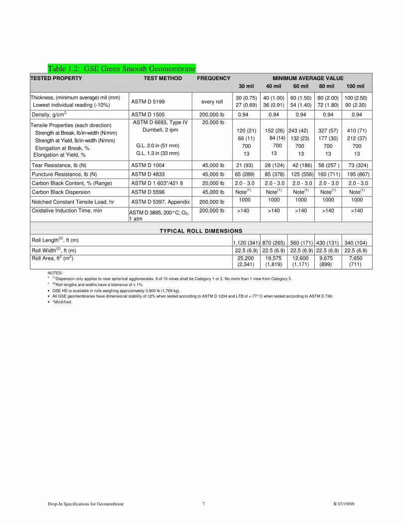
2. Table 1.2 for green HDPE
3. Table 1.3 for white-surfaced HDPE
a) The geomembrane shall be a white-surfaced, coextruded geomembrane.
b) The white surface shall be installed upwards.
4. Table 1.4 for smooth conductive HDPE
a) The geomembrane shall have a coextruded, electrically conductive layer.
b) The conductive layer is installed downward.
c) Electrical testing shall be performed after liner installation by the INSTALLER.
5. Table 1.5 for black LLDPE
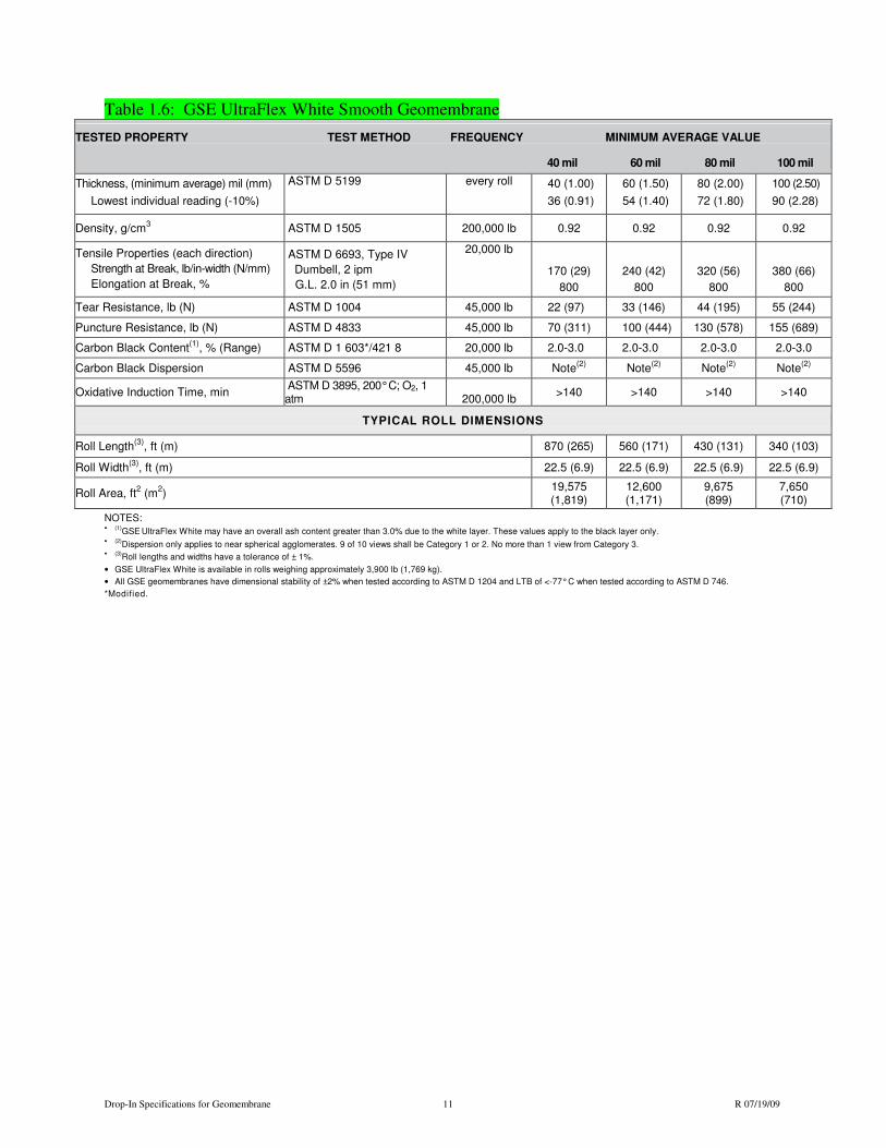
6. Table 1.6 for white-surfaced LLDPE
a) The geomembrane shall be a white-surfaced, coextruded geomembrane.
b) The white surface shall be installed upwards.

Drop-In Specifications for Geomembrane 6 R 07/19/09
Table 1.1: GSE HD Smooth Geomembrane TESTED PROPERTY TEST METHOD FREQUENCY MINIMUM AVERAGE VALUE
30 mil 40 mil 60 mil 80 mil 100 mil
Thickness, (minimum average) mil (mm)
Lowest individual reading (-10%)
ASTM D 5199
every roll
30 (0.75)
27 (0.69)
40 (1.00)
36 (0.91)
60 (1.50)
54 (1.40)
80 (2.00)
72 (1.80)
100 (2.50)
90 (2.30)
Density, g/cm3 ASTM D 1505 200,000 lb 0.94 0.94 0.94 0.94 0.94
Tensile Properties (each direction)
Strength at Break, lb/in-width (N/mm)
Strength at Yield, lb/in-width (N/mm)
Elongation at Break, %
Elongation at Yield, %
ASTM D 6693, Type IV
Dumbell, 2 ipm
G.L. 2.0 in (51 mm)
G.L. 1.3 in (33 mm)
20,000 lb
120 (21)
66 (11)
700
13
152 (26)
84 (14)
700
13
243 (42)
132 (23)
700
13
327 (57)
177 (30)
700
13
410 (71)
212 (37)
700
13
Tear Resistance, lb (N) ASTM D 1004 45,000 lb 21 (93) 28 (124) 42 (186) 58 (257 ) 73 (324)
Puncture Resistance, lb (N) ASTM D 4833 45,000 lb 65 (289) 85 (378) 125 (556) 160 (711) 195 (867)
Carbon Black Content, % (Range) ASTM D 1 603*/421 8 20,000 lb 2.0 - 3.0 2.0 - 3.0 2.0 - 3.0 2.0 - 3.0 2.0 - 3.0
Carbon Black Dispersion ASTM D 5596 45,000 lb Note(1) Note
(1) Note(1) Note
(1) Note(1)
Notched Constant Tensile Load, hr ASTM D 5397, Appendix 200,000 lb 1000 1000 1000 1000 1000
Oxidative Induction Time, min
ASTM D 3895, 200°C; O2, 1 atm
200,000 lb
>140
>140
>140
>140
>140
TYPICAL ROLL DIMENSIONS
Roll Length(2)
, ft (m) 1,120 (341) 870 (265) 560 (171) 430 (131) 340 (104)
Roll Width(2)
, ft (m) 22.5 (6.9) 22.5 (6.9) 22.5 (6.9) 22.5 (6.9) 22.5 (6.9)
Roll Area, ft2 (m
2) 25,200
(2,341) 19,575 (1,819)
12,600 (1,171)
9,675 (899)
7,650 (711)
NOTES: •
(1)
Dispersion only applies to near spherical agglomerates. 9 of 10 views shall be Category 1 or 2. No more than 1 view from Category 3. •
(2)
Roll lengths and widths have a tolerance of ± 1%.
• GSE HD is available in rolls weighing approximately 3,900 lb (1,769 kg).
• All GSE geomembranes have dimensional stability of ±2% when tested according to ASTM D 1204 and LTB of <-77° C when tested according to ASTM D 746.
• *Modified.
Drop-In Specifications for Geomembrane 7 R 07/19/09
Table 1.2: GSE Green Smooth Geomembrane TESTED PROPERTY TEST METHOD FREQUENCY MINIMUM AVERAGE VALUE
30 mil 40 mil 60 mil 80 mil 100 mil
Thickness, (minimum average) mil (mm)
Lowest individual reading (-10%)
ASTM D 5199
every roll
30 (0.75)
27 (0.69)
40 (1.00)
36 (0.91)
60 (1.50)
54 (1.40)
80 (2.00)
72 (1.80)
100 (2.50)
90 (2.30)
Density, g/cm3 ASTM D 1505 200,000 lb 0.94 0.94 0.94 0.94 0.94
Tensile Properties (each direction)
Strength at Break, lb/in-width (N/mm)
Strength at Yield, lb/in-width (N/mm)
Elongation at Break, %
Elongation at Yield, %
ASTM D 6693, Type IV
Dumbell, 2 ipm
G.L. 2.0 in (51 mm)
G.L. 1.3 in (33 mm)
20,000 lb
120 (21)
66 (11)
700
13
152 (26)
84 (14)
700
13
243 (42)
132 (23)
700
13
327 (57)
177 (30)
700
13
410 (71)
212 (37)
700
13
Tear Resistance, lb (N) ASTM D 1004 45,000 lb 21 (93) 28 (124) 42 (186) 58 (257 ) 73 (324)
Puncture Resistance, lb (N) ASTM D 4833 45,000 lb 65 (289) 85 (378) 125 (556) 160 (711) 195 (867)
Carbon Black Content, % (Range) ASTM D 1 603*/421 8 20,000 lb 2.0 - 3.0 2.0 - 3.0 2.0 - 3.0 2.0 - 3.0 2.0 - 3.0
Carbon Black Dispersion ASTM D 5596 45,000 lb Note(1)
Note(1) Note
(1) Note(1) Note
(1)
Notched Constant Tensile Load, hr ASTM D 5397, Appendix 200,000 lb 1000 1000 1000 1000 1000
Oxidative Induction Time, min ASTM D 3895, 200° C; O2, 1 atm
200,000 lb >140 >140 >140 >140 >140
TYPICAL ROLL DIMENSIONS
Roll Length(2)
, ft (m) 1,120 (341) 870 (265) 560 (171) 430 (131) 340 (104)
Roll Width(2)
, ft (m) 22.5 (6.9) 22.5 (6.9) 22.5 (6.9) 22.5 (6.9) 22.5 (6.9)
Roll Area, ft2 (m
2) 25,200
(2,341) 19,575 (1,819)
12,600 (1,171)
9,675 (899)
7,650 (711)
NOTES: •
(1)
Dispersion only applies to near spherical agglomerates. 9 of 10 views shall be Category 1 or 2. No more than 1 view from Category 3. •
(2)
Roll lengths and widths have a tolerance of ± 1%.
• GSE HD is available in rolls weighing approximately 3,900 lb (1,769 kg).
• All GSE geomembranes have dimensional stability of ±2% when tested according to ASTM D 1204 and LTB of <-77° C when tested according to ASTM D 746.
• *Modified.

Drop-In Specifications for Geomembrane 8 R 07/19/09
Table 1.3: GSE White Smooth Geomembrane
TESTED PROPERTY TEST METHOD FREQUENCY MINIMUM AVERAGE VALUE
30 mil 40 mil 60 mil 80 mil 100 mil Thickness, (minimum average) mil (mm)
Lowest individual reading (-10%)
ASTM D 5199 every roll 30 (0.75)
27 (0.69)
40 (1.00)
36 (0.91)
60 (1.50)
54 (1.40)
80 (2.00)
72 (1.80)
100 (2.50)
90 (2.30)
Density, g/cm3 ASTM D 1505 200,000 lb 0.94 0.94 0.94 0.94 0.94
Tensile Properties (each direction) Strength at
Break, lb/in-width (N/mm) Strength at Yield,
lb/in-width (N/mm) Elongation at Break, %
Elongation at Yield, %
ASTM D 6693, Type IV
Dumbell, 2 ipm
G.L. 2.0 in (51 mm)
G.L. 1.3 in (33 mm)
20,000 lb
120 (21)
66 (11)
700
13
152 (26)
84 (14)
700
13
243 (42)
132 (23)
700
13
327 (57)
177 (30)
700
13
410 (71)
212 (37)
700
13
Tear Resistance, lb (N) ASTM D 1004 45,000 lb 21 (93) 28 (124) 42 (186) 58 (257 ) 73 (324)
Puncture Resistance, lb (N) ASTM D 4833 45,000 lb 65 (289) 85 (378) 125 (556) 160 (711) 195 (867)
Carbon Black Content(1)
, % (Range) ASTM D 1 603*/421 8 20,000 lb 2.0 - 3.0 2.0 - 3.0 2.0 - 3.0 2.0 - 3.0 2.0 - 3.0
Carbon Black Dispersion ASTM D 5596 45,000 lb Note(2) Note
(2) Note(2) Note
(2) Note(2)
Notched Constant Tensile Load, hr ASTM D 5397, Appendix 200,000 lb 1000 1000 1000 1000 1000
Oxidative Induction Time, min ASTM D 3895, 200° C; O2, 1 atm
200,000 lb >140 >140 >140 >140 >140
TYPICAL ROLL DIMENSIONS
Roll Length(3)
, ft (m) 1,120 (341) 870 (265) 560 (171) 430 (131) 340 (104)
Roll Width(3)
, ft (m) 22.5 (6.9) 22.5 (6.9) 22.5 (6.9) 22.5 (6.9) 22.5 (6.9)
Roll Area, ft2 (m
2) 25,200
(2,341) 19,575 (1,819)
12,600 (1,171)
9,675 (899)
7,650 (711)
NOTES: •
(1)
GSE White may have an overall ash content greater than 3.0% due to the white layer. These values apply to the black layer only.
•
(2)
Dispersion only applies to near spherical agglomerates. 9 of 10 views shall be Category 1 or 2. No more than 1 view from Category 3. •
(3)
Roll lengths and widths have a tolerance of ± 1%.
• GSE White is available in rolls weighing approximately 3,900 lb (1,769 kg).
• All GSE geomembranes have dimensional stability of ±2% when tested according to ASTM D 1204 and LTB of <-77° C when tested according to ASTM D 746.
• *Modified.

Drop-In Specifications for Geomembrane 9 R 07/19/09
Table 1.4: GSE Conductive Smooth Geomembrane
TESTED PROPERTY TEST METHOD FREQUENCY MINIMUM AVERAGE VALUE
40 mil 60 mil 80 mil 100 mil
Thickness, (minimum average) mil (mm)
Lowest individual reading (-10%)
ASTM D 5199 every roll 40 (1.00)
36 (0.91)
60 (1.50)
54 (1.40)
80 (2.00)
72 (1.80)
100 (2.50)
90 (2.30)
Density, g/cm3 ASTM D 1505 200,000 lb 0.94 0.94 0.94 0.94
Tensile Properties (each direction)
Strength at Break, lb/in-width (N/mm)
Strength at Yield, lb/in-width (N/mm)
Elongation at Break, %
Elongation at Yield, %
ASTM D 6693, Type IV
Dumbell, 2 ipm
G.L. 2.0 in (51 mm)
G.L. 1.3 in (33 mm)
20,000 lb
152 (26)
84 (14)
700
13
243 (42)
132 (23)
700
13
327 (57)
177 (30)
700
13
410 (71)
212 (37)
700
13
Tear Resistance, lb (N) ASTM D 1004 45,000 lb 28 (124) 42 (186) 58 (257 ) 73 (324)
Puncture Resistance, lb (N) ASTM D 4833 45,000 lb 85 (378) 125 (556) 160 (711) 195 (867)
Carbon Black Content(1)
, % (Range) ASTM D 1 603*/421 8 20,000 lb 2.0 - 3.0 2.0 - 3.0 2.0 - 3.0 2.0 - 3.0
Carbon Black Dispersion ASTM D 5596 45,000 lb Note(2)
Note(2)
Note(2) Note
(2) Note(2)
Notched Constant Tensile Load, hr ASTM D 5397, Appendix 200,000 lb 1000 1000 1000 1000
Oxidative Induction Time, min ASTM D 3895, 200° C; O2, 1 atm
200,000 lb >140 >140 >140 >140
TYPICAL ROLL DIMENSIONS
Roll Length(3)
, ft (m) 870 (265) 560 (171) 430 (131) 340 (104)
Roll Width(3)
, ft (m) 22.5 (6.9) 22.5 (6.9) 22.5 (6.9) 22.5 (6.9)
Roll Area, ft2 (m
2) 19,575
(1,819) 12,600 (1,171)
9,675 (899)
7,650 (711)
NOTES: • (1)
GSE Conductive may have an overall ash content greater than 3.0%. These values apply to the non-conductive black layers.
• (2)Dispersion only applies to near spherical agglomerates. 9 of 10 views shall be Category 1 or 2. No more than 1 view from Category 3.
• (3)Roll lengths and widths have a tolerance of ± 1%.
• GSE Conductive is available in rolls weighing approximately 3,900 lb (1,769 kg).
• All GSE geomembranes have dimensional stability of ±2% when tested according to ASTM D 1204 and LTB of <-77° C when tested according to ASTM D 746.
• *Modified.

Drop-In Specifications for Geomembrane 10 R 07/19/09
Table 1.5: GSE UltraFlex Smooth Geomembrane
NOTES: •
(1)
Dispersion only applies to near spherical agglomerates. 9 of 10 views shall be Category 1 or 2. No more than 1 view from Category 3. •
(2)
Roll lengths and widths have a tolerance of ± 1%.
• GSE UltraFlex is available in rolls weighing approximately 3,900 lb (1,769 kg).
• All GSE geomembranes have dimensional stability of ±2% when tested according to ASTM D 1204 and LTB of <-77° C when tested according to ASTM D 746.
• *Modified.
TESTED PROPERTY TEST METHOD FREQUENCY MINIMUM AVERAGE VALUE
40 mil 60 mil 80 mil 100 mil
Thickness, (minimum average) mil (mm)
Lowest individual reading (-10%)
ASTM D 5199 every roll 40 (1.00)
36 (0.91)
60 (1.50)
54 (1.40)
80 (2.00)
72 (1.80)
100 (2.50)
90 (2.28)
Density, g/cm3 ASTM D 1505 200,000 lb 0.92 0.92 0.92 0.92
Tensile Properties (each direction)
Strength at Break, lb/in-width (N/mm)
Elongation at Break, %
ASTM D 6693, Type IV
Dumbell, 2 ipm
G.L. 2.0 in (51 mm)
20,000 lb
170 (29)
800
240 (42)
800
320 (56)
800
380 (66)
800
Tear Resistance, lb (N) ASTM D 1004 45,000 lb 22 (97) 33 (146) 44 (195) 55 (244)
Puncture Resistance, lb (N) ASTM D 4833 45,000 lb 70 (311) 100 (444) 130 (578) 155 (689)
Carbon Black Content, % (Range) ASTM D 1 603*/421 8 20,000 lb 2.0-3.0 2.0-3.0 2.0-3.0 2.0-3.0
Carbon Black Dispersion ASTM D 5596 45,000 lb Note(1)
Note(1) Note
(1) Note(1)
Oxidative Induction Time, min ASTM D 3895, 200° C; O2, 1 atm 200,000 lb
>140 >140 >140 >140
TYPICAL ROLL DIMENSIONS
Roll Length(2)
, ft (m) 870 (265) 560 (171) 430 (131) 340 (103)
Roll Width(2)
, ft (m) 22.5 (6.9) 22.5 (6.9) 22.5 (6.9) 22.5 (6.9)
Roll Area, ft2 (m
2)
19,575 (1,819)
12,600 (1,171)
9,675 (899)
7,650 (710)
Drop-In Specifications for Geomembrane 11 R 07/19/09
Table 1.6: GSE UltraFlex White Smooth Geomembrane
TESTED PROPERTY TEST METHOD FREQUENCY MINIMUM AVERAGE VALUE
40 mil 60 mil 80 mil 100 mil
Thickness, (minimum average) mil (mm)
Lowest individual reading (-10%)
ASTM D 5199 every roll 40 (1.00)
36 (0.91)
60 (1.50)
54 (1.40)
80 (2.00)
72 (1.80)
100 (2.50)
90 (2.28)
Density, g/cm3 ASTM D 1505 200,000 lb 0.92 0.92 0.92 0.92
Tensile Properties (each direction)
Strength at Break, lb/in-width (N/mm)
Elongation at Break, %
ASTM D 6693, Type IV
Dumbell, 2 ipm
G.L. 2.0 in (51 mm)
20,000 lb
170 (29)
800
240 (42)
800
320 (56)
800
380 (66)
800
Tear Resistance, lb (N) ASTM D 1004 45,000 lb 22 (97) 33 (146) 44 (195) 55 (244)
Puncture Resistance, lb (N) ASTM D 4833 45,000 lb 70 (311) 100 (444) 130 (578) 155 (689)
Carbon Black Content(1)
, % (Range) ASTM D 1 603*/421 8 20,000 lb 2.0-3.0 2.0-3.0 2.0-3.0 2.0-3.0
Carbon Black Dispersion ASTM D 5596 45,000 lb Note(2)
Note(2) Note
(2) Note(2)
Oxidative Induction Time, min ASTM D 3895, 200° C; O2, 1 atm 200,000 lb
>140 >140 >140 >140
TYPICAL ROLL DIMENSIONS
Roll Length(3)
, ft (m) 870 (265) 560 (171) 430 (131) 340 (103)
Roll Width(3)
, ft (m) 22.5 (6.9) 22.5 (6.9) 22.5 (6.9) 22.5 (6.9)
Roll Area, ft2 (m
2)
19,575 (1,819)
12,600 (1,171)
9,675 (899)
7,650 (710)
NOTES: •
(1)
GSE UltraFlex White may have an overall ash content greater than 3.0% due to the white layer. These values apply to the black layer only.
•
(2)
Dispersion only applies to near spherical agglomerates. 9 of 10 views shall be Category 1 or 2. No more than 1 view from Category 3. •
(3)
Roll lengths and widths have a tolerance of ± 1%.
• GSE UltraFlex White is available in rolls weighing approximately 3,900 lb (1,769 kg).
• All GSE geomembranes have dimensional stability of ±2% when tested according to ASTM D 1204 and LTB of <-77° C when tested according to ASTM D 746.
*Modified.
Drop-In Specifications for Geomembrane 12 R 07/19/09
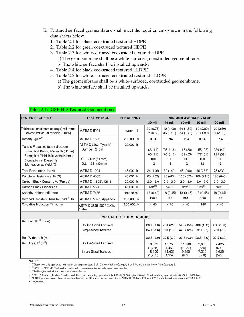
E. Textured surfaced geomembrane shall meet the requirements shown in the following
data sheets below.
1. Table 2.1 for black coextruded textured HDPE
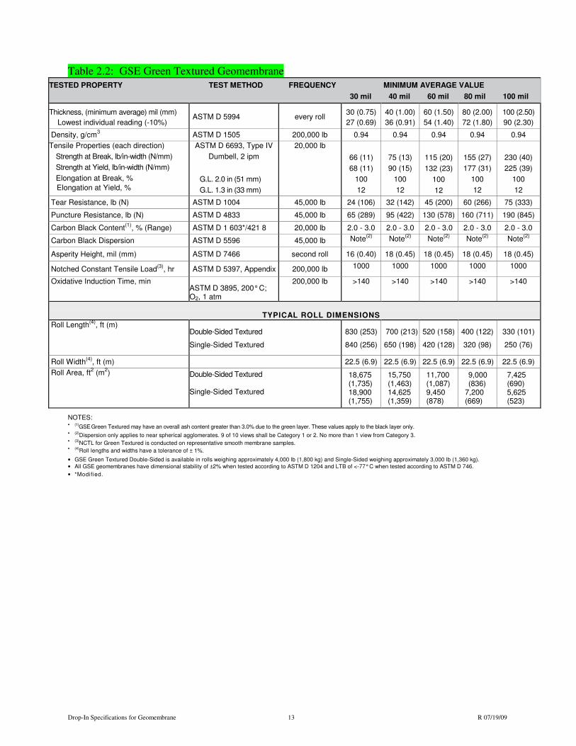
2. Table 2.2 for green coextruded textured HDPE
3. Table 2.3 for white-surfaced coextruded textured HDPE
a) The geomembrane shall be a white-surfaced, coextruded geomembrane.
b) The white surface shall be installed upwards.
4. Table 2.4 for black coextruded textured LLDPE
5. Table 2.5 for white-surfaced coextruded textured LLDPE
a) The geomembrane shall be a white-surfaced, coextruded geomembrane.
b) The white surface shall be installed upwards.
Table 2.1: GSE HD Textured Geomembrane
NOTES: •
(1)
Dispersion only applies to near spherical agglomerates. 9 of 10 views shall be Category 1 or 2. No more than 1 view from Category 3. •
(2)
NCTL for GSE I-ID Textured is conducted on representative smooth membrane samples. •
(3)
Roll lengths and widths have a tolerance of ± 1%.
• GSE I-ID Textured Double-Sided is available in rolls weighing approximately 4,000 lb (1,800 kg) and Single-Sided weighing approximately 3,000 lb (1,360 kg).
• All GSE geomembranes have dimensional stability of ±2% when tested according to ASTM D 1204 and LTB of <-77° C when tested according to ASTM D 746.
• *Modified.
TESTED PROPERTY TEST METHOD FREQUENCY MINIMUM AVERAGE VALUE
30 mil 40 mil 60 mil 80 mil 100 mil
Thickness, (minimum average) mil (mm)
Lowest individual reading (-10%)
ASTM D 5994
every roll
30 (0.75)
27 (0.69)
40 (1.00)
36 (0.91)
60 (1.50)
54 (1.40)
80 (2.00)
72 (1.80)
100 (2.50)
90 (2.30)
Density, g/cm3 ASTM D 1505 200,000 lb 0.94 0.94 0.94 0.94 0.94
Tensile Properties (each direction)
Strength at Break, lb/in-width (N/mm)
Strength at Yield, lb/in-width (N/mm)
Elongation at Break, %
Elongation at Yield, %
ASTM D 6693, Type IV
Dumbell, 2 ipm
G.L. 2.0 in (51 mm)
G.L. 1.3 in (33 mm)
20,000 lb
66 (11)
68 (11)
100
12
75 (13)
90 (15)
100
12
115 (20)
132 (23)
100
12
155 (27)
177 (31)
100
12
230 (40)
225 (39)
100
12
Tear Resistance, lb (N) ASTM D 1004 45,000 lb 24 (106) 32 (142) 45 (200) 60 (266) 75 (333)
Puncture Resistance, lb (N) ASTM D 4833 45,000 lb 65 (289) 95 (422) 130 (578) 160 (711) 190 (845)
Carbon Black Content, % (Range) ASTM D 1 603*/421 8 20,000 lb 2.0 - 3.0 2.0 - 3.0 2.0 - 3.0 2.0 - 3.0 2.0 - 3.0
Carbon Black Dispersion ASTM D 5596 45,000 lb Note(1) Note
(1) Note(1) Note
(1) Note(1)
Asperity Height, mil (mm) ASTM D 7466 second roll 16 (0.40) 18 (0.45) 18 (0.45) 18 (0.45) 18 (0.45)
Notched Constant Tensile Load(2)
, hr ASTM D 5397, Appendix 200,000 lb 1000 1000 1000 1000 1000
Oxidative Induction Time, min ASTM D 3895, 200° C; O2, 1 atm
200,000 lb >140 >140 >140 >140 >140
TYPICAL ROLL DIMENSIONS
Roll Length(3)
, ft (m) Double-Sided Textured
Single-Sided Textured
830 (253)
840 (256)
700 (213)
650 (198)
520 (158)
420 (128)
400 (122)
320 (98)
330 (101)
250 (76)
Roll Width(3)
, ft (m)
22.5 (6.9) 22.5 (6.9) 22.5 (6.9) 22.5 (6.9) 22.5 (6.9)
Roll Area, ft2 (m
2) Double-Sided Textured
Single-Sided Textured
18,675 (1,735) 18,900 (1,755)
15,750 (1,463) 14,625 (1,359)
11,700 (1,087) 9,450 (878)
9,000 (836) 7,200 (669)
7,425 (690) 5,625 (523)
Drop-In Specifications for Geomembrane 13 R 07/19/09
Table 2.2: GSE Green Textured Geomembrane
TESTED PROPERTY TEST METHOD FREQUENCY MINIMUM AVERAGE VALUE
30 mil 40 mil 60 mil 80 mil 100 mil Thickness, (minimum average) mil (mm)
Lowest individual reading (-10%)
ASTM D 5994
every roll
30 (0.75)
27 (0.69)
40 (1.00)
36 (0.91)
60 (1.50)
54 (1.40)
80 (2.00)
72 (1.80)
100 (2.50)
90 (2.30)
Density, g/cm3 ASTM D 1505 200,000 lb 0.94 0.94 0.94 0.94 0.94
Tensile Properties (each direction)
Strength at Break, lb/in-width (N/mm)
Strength at Yield, lb/in-width (N/mm)
Elongation at Break, %
Elongation at Yield, %
ASTM D 6693, Type IV
Dumbell, 2 ipm
G.L. 2.0 in (51 mm)
G.L. 1.3 in (33 mm)
20,000 lb
66 (11)
68 (11)
100
12
75 (13)
90 (15)
100
12
115 (20)
132 (23)
100
12
155 (27)
177 (31)
100
12
230 (40)
225 (39)
100
12
Tear Resistance, lb (N) ASTM D 1004 45,000 lb 24 (106) 32 (142) 45 (200) 60 (266) 75 (333)
Puncture Resistance, lb (N) ASTM D 4833 45,000 lb 65 (289) 95 (422) 130 (578) 160 (711) 190 (845)
Carbon Black Content(1)
, % (Range) ASTM D 1 603*/421 8 20,000 lb 2.0 - 3.0 2.0 - 3.0 2.0 - 3.0 2.0 - 3.0 2.0 - 3.0
Carbon Black Dispersion ASTM D 5596 45,000 lb Note(2) Note
(2) Note(2) Note
(2) Note(2)
Asperity Height, mil (mm) ASTM D 7466 second roll 16 (0.40) 18 (0.45) 18 (0.45) 18 (0.45) 18 (0.45)
Notched Constant Tensile Load(3)
, hr ASTM D 5397, Appendix 200,000 lb 1000 1000 1000 1000 1000
Oxidative Induction Time, min ASTM D 3895, 200° C; O2, 1 atm
200,000 lb >140 >140 >140 >140 >140
TYPICAL ROLL DIMENSIONS
Roll Length(4)
, ft (m) Double-Sided Textured
Single-Sided Textured
830 (253)
840 (256)
700 (213)
650 (198)
520 (158)
420 (128)
400 (122)
320 (98)
330 (101)
250 (76)
Roll Width(4)
, ft (m) 22.5 (6.9) 22.5 (6.9) 22.5 (6.9) 22.5 (6.9) 22.5 (6.9)
Roll Area, ft2 (m
2) Double-Sided Textured
Single-Sided Textured
18,675 (1,735) 18,900 (1,755)
15,750 (1,463) 14,625 (1,359)
11,700 (1,087) 9,450 (878)
9,000 (836)
7,200 (669)
7,425 (690) 5,625 (523)
NOTES: •
(1)
GSE Green Textured may have an overall ash content greater than 3.0% due to the green layer. These values apply to the black layer only.
•
(2)
Dispersion only applies to near spherical agglomerates. 9 of 10 views shall be Category 1 or 2. No more than 1 view from Category 3. •
(3)
NCTL for Green Textured is conducted on representative smooth membrane samples. •
(4)
Roll lengths and widths have a tolerance of ± 1%.
• GSE Green Textured Double-Sided is available in rolls weighing approximately 4,000 lb (1,800 kg) and Single-Sided weighing approximately 3,000 lb (1,360 kg).
• All GSE geomembranes have dimensional stability of ±2% when tested according to ASTM D 1204 and LTB of <-77° C when tested according to ASTM D 746.
• *Modified.
Drop-In Specifications for Geomembrane 14 R 07/19/09
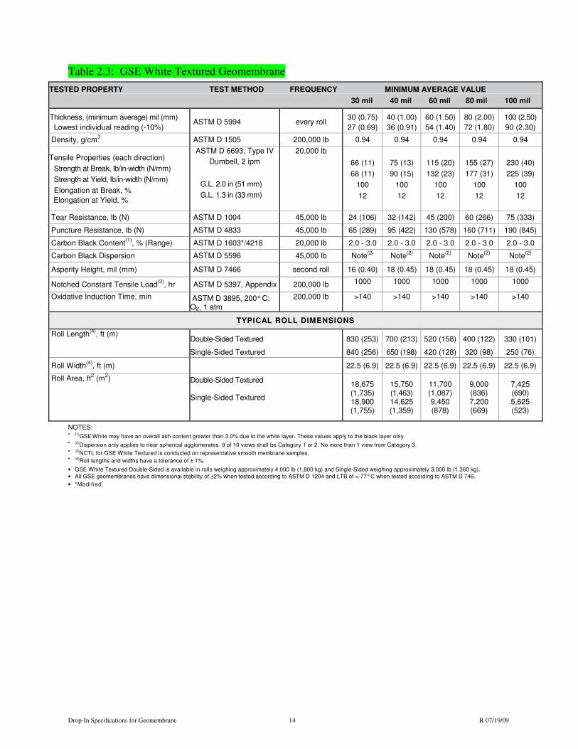
Table 2.3: GSE White Textured Geomembrane
NOTES: •
(1)
GSE White may have an overall ash content greater than 3.0% due to the white layer. These values apply to the black layer only.
•
(2)
Dispersion only applies to near spherical agglomerates. 9 of 10 views shall be Category 1 or 2. No more than 1 view from Category 3. •
(3)
NCTL for GSE White Textured is conducted on representative smooth membrane samples. •
(4)
Roll lengths and widths have a tolerance of ± 1%.
• GSE White Textured Double-Sided is available in rolls weighing approximately 4,000 lb (1,800 kg) and Single-Sided weighing approximately 3,000 lb (1,360 kg).
• All GSE geomembranes have dimensional stability of ±2% when tested according to ASTM D 1204 and LTB of <-77° C when tested according to ASTM D 746.
• *Modified.
TESTED PROPERTY TEST METHOD FREQUENCY MINIMUM AVERAGE VALUE
30 mil 40 mil 60 mil 80 mil 100 mil
Thickness, (minimum average) mil (mm)
Lowest individual reading (-10%)
ASTM D 5994
every roll
30 (0.75)
27 (0.69)
40 (1.00)
36 (0.91)
60 (1.50)
54 (1.40)
80 (2.00)
72 (1.80)
100 (2.50)
90 (2.30)
Density, g/cm3 ASTM D 1505 200,000 lb 0.94 0.94 0.94 0.94 0.94
Tensile Properties (each direction)
Strength at Break, lb/in-width (N/mm)
Strength at Yield, lb/in-width (N/mm)
Elongation at Break, %
Elongation at Yield, %
ASTM D 6693, Type IV
Dumbell, 2 ipm
G.L. 2.0 in (51 mm)
G.L. 1.3 in (33 mm)
20,000 lb
66 (11)
68 (11)
100
12
75 (13)
90 (15)
100
12
115 (20)
132 (23)
100
12
155 (27)
177 (31)
100
12
230 (40)
225 (39)
100
12
Tear Resistance, lb (N) ASTM D 1004 45,000 lb 24 (106) 32 (142) 45 (200) 60 (266) 75 (333)
Puncture Resistance, lb (N) ASTM D 4833 45,000 lb 65 (289) 95 (422) 130 (578) 160 (711) 190 (845)
Carbon Black Content(1)
, % (Range) ASTM D 1603*/4218 20,000 lb 2.0 - 3.0 2.0 - 3.0 2.0 - 3.0 2.0 - 3.0 2.0 - 3.0
Carbon Black Dispersion ASTM D 5596 45,000 lb Note(2)
Note(2)
Note(2) Note
(2) Note(2)
Asperity Height, mil (mm) ASTM D 7466 second roll 16 (0.40) 18 (0.45) 18 (0.45) 18 (0.45) 18 (0.45)
Notched Constant Tensile Load(3)
, hr ASTM D 5397, Appendix 200,000 lb 1000 1000 1000 1000 1000
Oxidative Induction Time, min ASTM D 3895, 200° C; O2, 1 atm
200,000 lb >140 >140 >140 >140 >140
TYPICAL ROLL DIMENSIONS
Roll Length(4)
, ft (m) Double-Sided Textured
Single-Sided Textured
830 (253)
840 (256)
700 (213)
650 (198)
520 (158)
420 (128)
400 (122)
320 (98)
330 (101)
250 (76)
Roll Width(4)
, ft (m)
22.5 (6.9) 22.5 (6.9) 22.5 (6.9) 22.5 (6.9) 22.5 (6.9)
Roll Area, ft2 (m
2) Double-Sided Textured
Single-Sided Textured
18,675 (1,735) 18,900 (1,755)
15,750 (1,463) 14,625 (1,359)
11,700 (1,087) 9,450 (878)
9,000 (836) 7,200 (669)
7,425 (690) 5,625 (523)

Drop-In Specifications for Geomembrane 15 R 07/19/09
Table 2.4: GSE UltraFlex Textured Geomembrane
NOTES: •
(1)
Dispersion only applies to near spherical agglomerates. 9 of 10 views shall be Category 1 or 2. No more than 1 view from Category 3. •
(2)
Roll lengths and widths have a tolerance of ± 1%.
• GSE UltraFlex Textured Double-Sided is available in rolls weighing approximately 4,000 lb (1,800 kg) and Single-Sided weighing approximately 3,000 lb (1,360 kg).
• All GSE geomembranes have dimensional stability of ±2% when tested according to ASTM D 1204 and LTB of <-77° C when tested according to ASTM D 746.
• *Modified.
TESTED PROPERTY TEST METHOD FREQUENCY MINIMUM AVERAGE VALUE
40 mil 60 mil 80 mil 100 mil
Thickness, (minimum average) mil (mm)
Lowest individual reading (-10%)
ASTM D 5994 every roll 40 (1.00)
36 (0.91)
60 (1.50)
54 (1.40)
80 (2.00)
72 (1.80)
100 (2.50)
90 (2.28)
Density, g/cm3 ASTM D 1505 200,000 lb 0.92 0.92 0.92 0.92
Tensile Properties (each direction)
Strength at Break, lb/in-width (N/mm)
Elongation at Break, %
ASTM D 6693, Type IV
Dumbell, 2 ipm
G.L. 2.0 in (51 mm)
20,000 lb
115 (20)
500
168 (29)
500
224 (39)
500
270 (47)
500
Tear Resistance, lb (N) ASTM D 1004 45,000 lb 25 (111) 38 (169) 50 (222) 60 (266)
Puncture Resistance, lb (N) ASTM D 4833 45,000 lb 65 (289) 95 (422) 125 (556) 140 (622)
Carbon Black Content, % (Range) ASTM D 1 603*/421 8 20,000 lb 2.0-3.0 2.0-3.0 2.0-3.0 2.0-3.0
Carbon Black Dispersion ASTM D 5596 45,000 lb Note(1) Note
(1) Note(1) Note
(1)
Asperity Height, mil (mm) ASTM D 7466 second roll 18 (0.45) 18 (0.45) 18 (0.45) 18 (0.45)
Oxidative Induction Time, min ASTM D 3895, 200° C; O2, 1 atm 200,000 lb
>140 >140 >140 >140
TYPICAL ROLL DIMENSIONS
Roll Length(2)
, ft (m) Double-Sided Textured
Single-Sided Textured
700 (213)
650 (198)
520 (158)
420 (128)
400 (122)
320 (98)
330 (100)
250 (76)
Roll Width(2)
, ft (m) 22.5 (6.9) 22.5 (6.9) 22.5 (6.9) 22.5 (6.9)
Roll Area, ft2 (m
2) Double-Sided Textured
Single-Sided Textured
15,750 (1,463)
14,625 (1,359)
11,700 (1,087)
9,450 (878)
9,000 (836)
7,200 (669)
7,425 (689)
5,625 (522)

Drop-In Specifications for Geomembrane 16 R 07/19/09
Table 2.5: GSE UltraFlex White Textured Geomembrane TESTED PROPERTY TEST METHOD FREQUENCY MINIMUM AVERAGE VALUE
40 mil 60 mil 80 mil 100 mil
Thickness, (minimum average) mil (mm)
Lowest individual reading (-10%)
ASTM D 5994 every roll 40 (1.00)
36 (0.91)
60 (1.50)
54 (1.40)
80 (2.00)
72 (1.80)
100 (2.50)
90 (2.28)
Density, g/cm3 ASTM D 1505 200,000 lb 0.92 0.92 0.92 0.92
Tensile Properties (each direction)
Strength at Break, lb/in-width (N/mm)
Elongation at Break, %
ASTM D 6693, Type IV
Dumbell, 2 ipm
G.L. 2.0 in (51 mm)
20,000 lb
115 (20)
500
168 (29)
500
224 (39)
500
270 (47)
500
Tear Resistance, lb (N) ASTM D 1004 45,000 lb 25 (111) 38 (169) 50 (222) 60 (266)
Puncture Resistance, lb (N) ASTM D 4833 45,000 lb 65 (289) 95 (422) 125 (556) 140 (622)
Carbon Black Content(1)
, % (Range) ASTM D 1 603*/421 8 20,000 lb 2.0-3.0 2.0-3.0 2.0-3.0 2.0-3.0
Carbon Black Dispersion ASTM D 5596 45,000 lb Note(2)
Note(2) Note
(2) Note(2)
Asperity Height, mil (mm) ASTM D 7466 second roll 18 (0.45) 18 (0.45) 18 (0.45) 18 (0.45)
Oxidative Induction Time, min ASTM D 3895, 200° C; O2, 1 atm
200,000 lb >140 >140 >140 >140
TYPICAL ROLL DIMENSIONS
Roll Length(3)
, ft (m) Double-Sided Textured
Single-Sided Textured
700 (213)
650 (198)
520 (158)
420 (128)
400 (122)
320 (98)
330 (100)
250 (76)
Roll Width(3)
, ft (m) 22.5 (6.9) 22.5 (6.9) 22.5 (6.9) 22.5 (6.9)
Roll Area, ft2 (m
2) Double-Sided Textured
Single-Sided Textured
15,750 (1,463)
14,625 (1,359)
11,700 (1,087)
9,450 (878)
9,000 (836)
7,200 (669)
7,425 (689)
5,625 (522)
NOTES: •
(1)
GSE UltraFlex White Textured may have an overall ash content greater than 3.0% due to the white layer. These values apply to the black layer only.
•
(2)
Dispersion only applies to near spherical agglomerates. 9 of 10 views shall be Category 1 or 2. No more than 1 view from Category 3. •
(3)
Roll lengths and widths have a tolerance of ± 1%.
• GSE UltraFlex White Textured Double-Sided is available in rolls weighing approximately 4,000 lb (1,800 kg) and Single-Sided weighing approximately 3,000 lb (1,360 kg).
• All GSE geomembranes have dimensional stability of ±2% when tested according to ASTM D 1204 and LTB of <-77° C when tested according to ASTM D 746.
• *Modified.

Drop-In Specifications for Geomembrane 17 R 07/19/09
F. Extrudate Rod or Bead
1. Extrudate material shall be made from same type resin as the geomembrane.
2. Additives shall be thoroughly dispersed.
3. Materials shall be free of contamination by moisture or foreign matter.
1.10 EQUIPMENT
A. Welding equipment and accessories shall meet the following requirements:
1. Gauges showing temperatures in apparatus (extrusion welder) or wedge (wedge
welder) shall be present.
2. An adequate number of welding apparati shall be available to avoid delaying work.
3. Power source must be capable of providing constant voltage under combined line
load.
1.11 DEPLOYMENT
A. Assign each panel a simple and logical identifying code. The coding system shall be
subject to approval and shall be determined at the job site.
B. Visually inspect the geomembrane during deployment for imperfections and mark faulty
or suspect areas.
C. Deployment of geomembrane panels shall be performed in a manner that will comply
with the following guidelines:
1. Geomembranes shall be installed according to site-specific specifications, and GSE
Conductive should be installed with the Conductive layer down.
Note: A spark tester or ohm meter can be used to determine Conductive layer.
2. Unroll geomembrane using methods that will not damage geomembrane and will
protect underlying surface from damage (spreader bar, protected equipment bucket).
3. Place ballast (commonly sandbags) on geomembrane which will not damage
geomembrane to prevent wind uplift.
4. Personnel walking on geomembrane shall not engage in activities or wear shoes that
could damage it. Smoking will not be permitted on the geomembrane.
5. Do not allow heavy vehicular traffic directly on geomembrane. Rubber-tired ATV’s
and trucks are acceptable if wheel contact is less than 6 psi.
6. Protect geomembrane in areas of heavy traffic by placing protective cover over the
geomembrane.
D. Sufficient material (slack) shall be provided to allow for thermal expansion and
contraction of the material.
1.12 FIELD SEAMING
A. Seams shall meet the following requirements:
1. To the maximum extent possible, orient seams parallel to line of slope, i.e., down and
not across slope.
2. Minimize number of field seams in corners, odd-shaped geometric locations and
outside corners.
3. Slope seams (panels) shall extend a minimum of five-feet beyond the grade break into
the flat area.
4. Use a sequential seam numbering system compatible with panel numbering system
that is agreeable to the CONSULTANT and INSTALLER.

Drop-In Specifications for Geomembrane 18 R 07/19/09
5. Align seam overlaps consistent with the requirements of the welding equipment being
used. A 6-inch overlap is commonly suggested.
B. During Welding Operations
1. Provide at least one Master Seamer who shall provide direct supervision over other
welders as necessary.
C. Extrusion Welding
1. Hot-air tack adjacent pieces together using procedures that do not damage the
geomembrane.
2. Clean geomembrane surfaces by disc grinder or equivalent.
3. Purge welding apparatus of heat-degraded extrudate before welding.
D. Hot Wedge Welding
1. Welding apparatus shall be a self-propelled device equipped with an electronic
controller which displays applicable temperatures.
2. Clean seam area of dust, mud, moisture and debris immediately ahead of hot wedge
welder.
3. Protect against moisture build-up between sheets.
E. Trial Welds
1. Perform trial welds on geomembrane samples to verify welding equipment is
operating properly.
2. Make trial welds under the same surface and environmental conditions as the
production welds, i.e., in contact with subgrade and similar ambient temperature.
3. Minimum of two trial welds per day, per welding apparatus, one made prior to the
start of work and one completed at mid shift.
4. Cut four, one-inch wide by six-inch long test strips from the trial weld.
5. Quantitatively test specimens for peel adhesion, and then for shear strength.
6. Trial weld specimens shall pass when the results shown in the following tables for
HDPE and LLDPE are achieved in both peel and shear test.
Table 1.12.6A: Minimum Weld Values for HDPE Geomembranes Property
Test Method 30 (0.75) 40 (1.0) 60 (1.5) 80 (2.0) 100 (2.5) 120 (3.0)
Peel Strength (fusion), ppi (kN/m) Peel Strength (extrusion), ppi (kN/m)
ASTM D 6392 ASTM D 6392
49 (8.6) 39 (6.8)
65 (11.4) 52 (9.1)
98 (17.2) 78 (13.7)
130 (22.8) 104 (18.2)
162 (28.4) 130 (22.8)
196 (34.3) 157 (27.5)
Shear Strength (fusion & ext.), ppi (kN/m)
ASTM D 6392
61 (10.7)
81 (14.2)
121 (21.2)
162 (28.4)
203 (35.5)
242 (42.4)
Table 1.2.6B: Minimum Weld Values for HDPE Geomembranes Property
Test Method 30 (0.75) 40 (1.0) 60 (1.5) 80 (2.0) 100 (2.5)
Peel Strength (extrusion), ppi (kN/m) Peel Strength (fusion), ppi (kN/m)
ASTM D 6392 ASTM D 6392
36 (6.3) 38 (6.7)
48 (8.4) 50 (8.8)
72 (12.6) 75 (13.1)
96 (16.8) 100 (17.5)
120 (21.0) 125 (21.9)
Shear Strength (fusion & ext.), ppi (kN/m) ASTM D 6392 45 (7.9) 60 (10.5) 90 (15.8) 120 (21.0) 150 (26.3)
a. The break, when peel testing, occurs in the liner material itself, not through peel
separation (FTB).
b. The break is ductile.
7. Repeat the trial weld, in its entirety, when any of the trial weld samples fail in either
peel or shear.
8. No welding equipment or welder shall be allowed to perform production welds until
equipment and welders have successfully completed trial weld.
Drop-In Specifications for Geomembrane 19 R 07/19/09
F. Seaming shall not proceed when ambient air temperature or adverse weather conditions
jeopardize the integrity of the liner installation. INSTALLER shall demonstrate that
acceptable seaming can be performed by completing acceptable trial welds.
G. Defects and Repairs
1. Examine all seams and non-seam areas of the geomembrane for defects, holes,
blisters, undispersed raw materials, and any sign of contamination by foreign matter.
2. Repair and non-destructively test each suspect location in both seam and non-seam
areas. Do not cover geomembrane at locations that have been repaired until test
results with passing values are available.
1.13 FIELD QUALITY ASSURANCE
A. MANUFACTURER and INSTALLER shall participate in and conform to all terms and
requirements of the Owner’s quality assurance program. CONTRACTOR shall be
responsible for assuring this participation.
B. Quality assurance requirements are as specified in this Section and in the Field
Installation Quality Assurance Manual if it is included in the contract.
C. Field Testing
1. Non-destructive testing may be carried out as the seaming progresses or at completion
of all field seaming.
a. Vacuum Testing
1) Shall be performed in accordance with ASTM D 5641, Standard Practice for
Geomembrane Seam Evaluation by Vacuum Chamber.
b. Air Pressure Testing
1) Shall be performed in accordance with ASTM D 5820, Standard Practice for
Pressurized Air Channel Evaluation of Dual Seamed Geomembranes.
c. Spark Tesing
1) Shall be performed accordance with ASTM D 7240 Standard Practice for Leak
Location using Geomembranes with an Insulating Layer in Intimate Contact
with a Conductive Layer via Electrical Capacitance Technique (Conductive
Geomembrane Spark Test).
d. Other approved methods.
2. Destructive Testing (performed by CONSULTANT with assistance from
INSTALLER)
a. Location and Frequency of Testing
1) Collect destructive test samples at a frequency of one per every 1500 lineal feet
of seam length.
2) Test locations will be determined after seaming.
3) Exercise Method of Attributes as described by GRI GM-14 (Geosynthetic
Research Institute, http://www.geosynthetic-institute.org) to minimize test
samples taken.
b. Sampling Procedures are performed as follows:
1) INSTALLER shall cut samples at locations designated by the CONSULTANT
as the seaming progresses in order to obtain field laboratory test results before
the geomembrane is covered.
2) CONSULTANT will number each sample, and the location will be noted on the
installation as-built.
3) Samples shall be twelve (12) inches wide by minimal length with the seam
centered lengthwise.
Drop-In Specifications for Geomembrane 20 R 07/19/09
4) Cut a 2-inch wide strip from each end of the sample for field-testing.
5) Cut the remaining sample into two parts for distribution as follows:
a) One portion for INSTALLER, 12-inches by 12 inches
b) One portion for the Third Party laboratory, 12-inches by 18-inches
c) Additional samples may be archived if required.
6) Destructive testing shall be performed in accordance with ASTM D 6392,
Standard Test Method for Determing the Integrity of Non-Reinforced
Geomembrane Seams Produced Using Thermo-Fusion Methods.
7) INSTALLER shall repair all holes in the geomembrane resulting from
destructive sampling.
8) Repair and test the continuity of the repair in accordance with these
Specifications.
3. Failed Seam Procedures
a) If the seam fails, INSTALLER shall follow one of two options:
1) Reconstruct the seam between any two passed test locations.
2) Trace the weld to intermediate location at least 10 feet minimum or where the
seam ends in both directions from the location of the failed test.
b) The next seam welded using the same welding device is required to obtain an
additional sample, i.e., if one side of the seam is less than 10 feet long.
c) If sample passes, then the seam shall be reconstructed or capped between the test
sample locations.
d) If any sample fails, the process shall be repeated to establish the zone in which the
seam shall be reconstructed.
1.14 REPAIR PROCEDURES
A. Remove damaged geomembrane and replace with acceptable geomembrane materials if
damage cannot be satisfactorily repaired.
B. Repair any portion of unsatisfactory geomembrane or seam area failing a destructive or
non-destructive test.
C. INSTALLER shall be responsible for repair of defective areas.
D. Agreement upon the appropriate repair method shall be decided between
CONSULTANT and INSTALLER by using one of the following repair methods:
1. Patching- Used to repair large holes, tears, undispersed raw materials and
contamination by foreign matter.
2. Abrading and Re-welding- Used to repair short section of a seam.
3. Spot Welding- Used to repair pinholes or other minor, localized flaws or where
geomembrane thickness has been reduced.
4. Capping- Used to repair long lengths of failed seams.
5. Flap Welding- Used to extrusion weld the flap (excess outer portion) of a fusion weld
in lieu of a full cap.
6. Remove the unacceptable seam and replace with new material.
E. The following procedures shall be observed when a repair method is used:
1. All geomembrane surfaces shall be clean and dry at the time of repair.
2. Surfaces of the polyethylene which are to be repaired by extrusion welds shall be
lightly abraded to assure cleanliness.
3. Extend patches or caps at least 6 inches for extrusion welds and 4 inches for wedge
welds beyond the edge of the defect, and around all corners of patch material.
F. Repair Verification

Drop-In Specifications for Geomembrane 21 R 07/19/09
1. Number and log each patch repair (performed by CONSULTANT).
2. Non-destructively test each repair using methods specified in this Specification.
1.15 MEASUREMENT AND PAYMENT
A. Payment for geomembrane installation will be as per contract unit price per square foot,
as measured parallel to liner surface, including designed anchor trench material and is
based upon net lined area.
B. Net lined area is defined to be the true area of all surfaces to be lined plus designed
burial in all anchor trenches, rubsheets, and sacrificial layers.
C. Prices shall include full compensation for furnishing all labor, material, tools, equipment,
and incidentals.
D. Prices also include doing all the work involved in performing geomembrane installation
completely as shown on the drawing, as specified herein, and as directed by the
ENGINEER.
END OF SECTION