technical manual for the mobile data terminal - … mdt-100 technical manual v1.00.pdf · the mdt...
TRANSCRIPT
Technical Manual 1.00, Mobile Data Terminal
Logic IO www.logicio.com
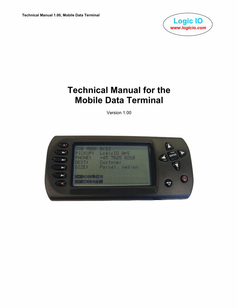
Technical Manual for the Mobile Data Terminal
Version 1.00

Logic IO ApS. Ph: (+45) 7625 0210 Holmboes Allé 14 Fax: (+45) 7625 0211 8700 Horsens Email: [email protected] Denmark www.logicio.com / www.rtcu.dk
Technical Manual 1.00, Mobile Data Terminal
Page 2 of 8
Logic IO www.logicio.com
Introduction
This manual contains technical documentation allowing easy installation and use of the unit. For programming information please consult the RTCU Programming Documentation and/or the RTCU IDE Online help. The Mobile Data Terminal (MDT) extends the RTCU units (MX2 / M11 series) with a flexible and easy-to-use user interface solution with many advanced features, allowing all kinds of two-way messaging applications to be implemented. The MDT is robust, field proven, and is packed to survive thermal extremes and vibrations. The MDT is easily connected to the RTCU units and includes the following features:
• High contrast graphic Liquid Crystal Display (LCD)
• 8 lines, 26 characters per line
• 13 tactile, user definable keys
• Built in piezo buzzer
• 10 user selectable backlight levels
• Two easy mounting options
• High-level VPL library
• Full simulator support in RTCU-IDE
• Built for tough environments
• Easy vehicle installation
• MDT on/off and standby functionality
Table of Contents
Introduction ......................................................................................................................... 2 Table of Contents................................................................................................................ 2 Graphical view..................................................................................................................... 3 External connections........................................................................................................... 4
Overview ......................................................................................................................... 4 Connector ‘1’ ................................................................................................................... 4 Connector ‘2’ ................................................................................................................... 4
Installation........................................................................................................................... 5 MX2 ................................................................................................................................. 5 M11i Series...................................................................................................................... 6 Power and standby modes .............................................................................................. 6
Mounting ............................................................................................................................. 7 Flexible suction cup. ........................................................................................................ 7 M3 mounting holes. ......................................................................................................... 7
Specifications for the Mobile Data Terminal ........................................................................ 8

Logic IO ApS. Ph: (+45) 7625 0210 Holmboes Allé 14 Fax: (+45) 7625 0211 8700 Horsens Email: [email protected] Denmark www.logicio.com / www.rtcu.dk
Technical Manual 1.00, Mobile Data Terminal
Page 3 of 8
Logic IO www.logicio.com
Graphical view
Figure 1: Front view
Interface cable 6 tactile keys
Large easy-to-read display (8 x 26)
7 tactile keys
M3 Brass insert M3 Brass insert
M3 Brass insert M3 Brass insert
Connector 2 Slot for suction bracket cup
Figure 2: Backside view
Logic IO ApS. Ph: (+45) 7625 0210 Holmboes Allé 14 Fax: (+45) 7625 0211 8700 Horsens Email: [email protected] Denmark www.logicio.com / www.rtcu.dk
Technical Manual 1.00, Mobile Data Terminal
Page 4 of 8
Logic IO www.logicio.com
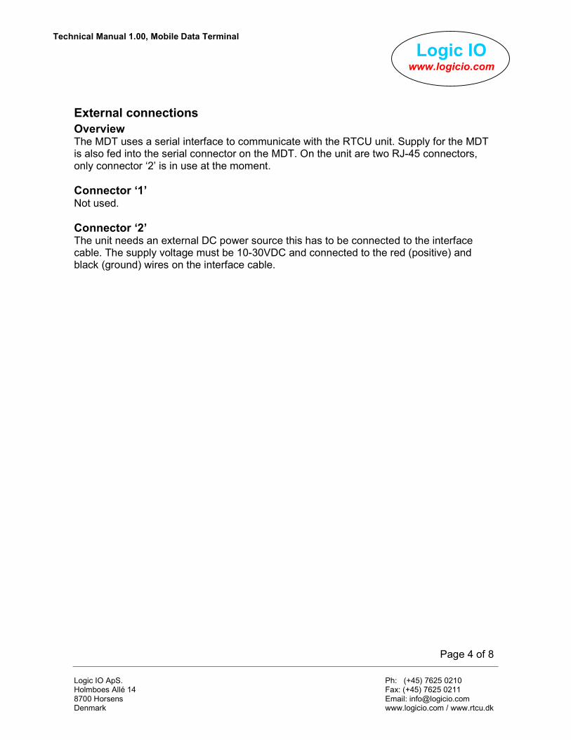
External connections
Overview The MDT uses a serial interface to communicate with the RTCU unit. Supply for the MDT is also fed into the serial connector on the MDT. On the unit are two RJ-45 connectors, only connector ‘2’ is in use at the moment.
Connector ‘1’ Not used.
Connector ‘2’ The unit needs an external DC power source this has to be connected to the interface cable. The supply voltage must be 10-30VDC and connected to the red (positive) and black (ground) wires on the interface cable.

Logic IO ApS. Ph: (+45) 7625 0210 Holmboes Allé 14 Fax: (+45) 7625 0211 8700 Horsens Email: [email protected] Denmark www.logicio.com / www.rtcu.dk
Technical Manual 1.00, Mobile Data Terminal
Page 5 of 8
Logic IO www.logicio.com
Installation
The interface cable provided in the MDT package is made by Logic IO. The external supply wires and data signal blue (MX2) / grey (M11) cable are wired into one (black) cable to the MDT unit. The total length of the cable is ~3.5m see the figure 3 below for details.
Figure 3: MX2 Cable dimensions
MX2 The blue cable must be inserted into serial port 2 on the MX2 unit, the black must be inserted into connector ‘2’ on the MDT unit, see figure 2 for placement of connector ‘2’ on the MDT. For further information on external connections on the MX2, see MX2 Technical Manual.
Figure 4: MX2 Cable
MX2 / M11i / M11Gi Serial Port 2
MDT Connector 2
External supply 10-30VDC
~3m ~0.5m
~0.5m

Logic IO ApS. Ph: (+45) 7625 0210 Holmboes Allé 14 Fax: (+45) 7625 0211 8700 Horsens Email: [email protected] Denmark www.logicio.com / www.rtcu.dk
Technical Manual 1.00, Mobile Data Terminal
Page 6 of 8
Logic IO www.logicio.com
M11i Series The grey cable must be inserted into serial port 2 on the M11i/M11Gi unit, the black must be inserted into connector ‘2’ on the MDT unit, see figure 2 for placement of connector ‘2’ on the MDT. For further information on external connections on the M11 series, see the appropriate M11i Series Technical Manual.
Figure 5: M11i / M11Gi Cable
Power and standby modes The MDT has two power modes with different behaviors and power consumption:
• Power: Controls the DC supply for the MDT, if turned off it’s not possible to resume operation by using the power-key. The MDT can only be turned on again from the VPL application running in the RTCU unit. Power savings are at maximum in this state.
• Standby: In standby mode the MDT will enter a power-saving mode where the LCD-display is turned off to save power. In this mode the MDT can still send the power-key events to the RTCU unit and therefore on user request resume normal operation. Power savings are minimal in this state.
For more information on this subject please consult the RTCU Programming Documentation and/or the RTCU IDE Online help.

Logic IO ApS. Ph: (+45) 7625 0210 Holmboes Allé 14 Fax: (+45) 7625 0211 8700 Horsens Email: [email protected] Denmark www.logicio.com / www.rtcu.dk
Technical Manual 1.00, Mobile Data Terminal
Page 7 of 8
Logic IO www.logicio.com
Mounting
There are two ways to mount the MDT unit these are described below.
Flexible suction cup. 1. Match the two slides on the bracket to the corresponding slots on the back of the
MDT unit until they firmly latch into place. 2. Find a smooth surface and clean it thoroughly. 3. Press the suction cup firmly to the surface while pulling the lever down to seal the
suction cup. 4. Hold the bracket base and bend the stalk to adjust the viewing position.
M3 mounting holes. The brass inserts on the backside can be used to mount the MDT on a custom made bracket. There are eight M3 mounting holes available, see figure 6 below for guidance. Be careful not to over tighten the screws as driving the screws in too far may cause damage, therefore use M3x6mm screws.
Figure 6: M3 brass insert placements

Logic IO ApS. Ph: (+45) 7625 0210 Holmboes Allé 14 Fax: (+45) 7625 0211 8700 Horsens Email: [email protected] Denmark www.logicio.com / www.rtcu.dk
Technical Manual 1.00, Mobile Data Terminal
Page 8 of 8
Logic IO www.logicio.com
Specifications for the Mobile Data Terminal
26 Characters/line
160 x 80
8
Pixel resolution
Lines LCD
VDC 30 - 10 Operating Voltage
Unit in Power OFF mode Unit in Standby mode Unit ON with full backlight
Currents are measured @ 12VDC
mA mA mA
0 40 70
Max
Typ
Min Power supply
Measured 1m in front of unit
kHz
dB
90
1
-
80
Frequency
Sound level Piezo buzzer
ºC +60 - -25 Operating temperature
Kg 0.226 Weight
Without mounting brackets W 185 x H 85 x D 32 mm External dimensions
External interface: • RJ45 for seriel interface and power supply • Comes with interface cable for either the RTCU MX2 or RTCU M11 / M11i Series.
UV stabilized, high-temperature resistant
Enclosure
ºC +85 - -40 Storage temperature
Humidity % 95