stand 06/2015 technical manual mdt switch … 06/2015 technical manual mdt switch actuator/fancoil...
TRANSCRIPT
MDT technologies GmbH,Geschäftsbereich Gebäudeautomation
Tel.: +49-2263-880•Fax: +49-2263-4588•E-Mail:[email protected]•www.mdtautomation.de 1
1
Stand 06/2015
Technical Manual
MDT Switch Actuator/FanCoil
AKK-03UP.01
Technical Manual Switch Actuator 3-fold, FanCoil
MDT technologies GmbH • 51766 Engelskirchen • Papiermühle 1
Tel.: +49-2263-880 • Fax: +49-2263-4588 • [email protected] • www.mdt.de 2
2
1 Content 1 Content ................................................................................................................................................. 2
2 Overview ............................................................................................................................................... 4
2.1 Overview Devices .......................................................................................................................... 4
2.2 Exemplary circuit diagram ............................................................................................................ 4
2.3 Usage & Areas of Apllication ......................................................................................................... 5
2.4 Design & Usage .............................................................................................................................. 6
2.5 Setting at the ETS-Software ........................................................................................................... 7
2.6 Starting Up ..................................................................................................................................... 7
3 Communication objects ........................................................................................................................ 8
3.1 Mode: Actuator ............................................................................................................................. 8
3.1.1 Overview and Usage ............................................................................................................... 8
3.1.2 Default-Settings of the Communication Objects .................................................................. 10
3.2 Mode: FanCoil ............................................................................................................................. 11
3.2.1 Overview and Usage ............................................................................................................. 11
3.2.2 Default settings of the communication objects ................................................................... 16
4 Configuration of the operating mode ................................................................................................ 18
4.1 General Settings .......................................................................................................................... 18
5 Reference ETS-Parameter - Actuator ................................................................................................. 19
5.1 Channel selection ........................................................................................................................ 19
5.2 Identical parameter ..................................................................................................................... 20
5.2.1 Relay operating mode .......................................................................................................... 20
5.2.2 Central function .................................................................................................................... 21
5.2.3 Behavior at block/unblock .................................................................................................... 21
5.3 Switching output ......................................................................................................................... 23
5.3.1 Overview ............................................................................................................................... 23
5.3.2 On-/Off-delay ....................................................................................................................... 25
5.3.3 Logical functions ................................................................................................................... 26
5.3.4 Scene function ...................................................................................................................... 28
5.4 Staircase ...................................................................................................................................... 33
5.4.1 Overview ............................................................................................................................... 33
5.4.2 Staircase time ....................................................................................................................... 35
5.4.3 Prewarning und Warning ..................................................................................................... 36
5.4.4 Manual switch off ................................................................................................................. 37
5.4.5 Extend staircase time ........................................................................................................... 37
Technical Manual Switch Actuator 3-fold, FanCoil
MDT technologies GmbH • 51766 Engelskirchen • Papiermühle 1
Tel.: +49-2263-880 • Fax: +49-2263-4588 • [email protected] • www.mdt.de 3
3
6 Parameter - FanCoil ............................................................................................................................ 38
6.1 General Functions........................................................................................................................ 38
6.1.1 FanCoil-System ..................................................................................................................... 38
6.1.2 General FanCoil settings ....................................................................................................... 40
6.1.3 Blocking Functions ................................................................................................................ 43
6.1.4 Activation of further submenus ........................................................................................... 44
6.2 Additional Ventilation ................................................................................................................. 45
6.2.1 Automatic additional ventilation .......................................................................................... 45
6.2.2 Manual additional ventilation .............................................................................................. 45
6.3 Automatic Mode .......................................................................................................................... 46
6.3.1 Automatic Mode – Control Value ......................................................................................... 46
6.3.2 Automatic mode – Delta T .................................................................................................... 50
6.4 Direct Mode ................................................................................................................................. 54
6.4.1 binary coded ......................................................................................................................... 54
6.4.2 Step switch ........................................................................................................................... 54
6.4.3 - 1 Bit Up/Down .................................................................................................................... 54
6.5 State............................................................................................................................................. 55
6.5.1 Status Fan at heating/cooling mode active .......................................................................... 56
6.5.2 Status maximum control value ............................................................................................. 56
6.5.3 Status maximum Level.......................................................................................................... 56
7 Index ................................................................................................................................................... 57
7.1 List of figures ............................................................................................................................... 57
7.2 List of tables................................................................................................................................. 58
8 Attachment ......................................................................................................................................... 59
8.1 Statutory requirements ............................................................................................................... 59
8.2 Routine disposal .......................................................................................................................... 59
8.3 Assemblage .................................................................................................................................. 59
8.4 Datasheet .................................................................................................................................... 59

Technical Manual Switch Actuator 3-fold, FanCoil
MDT technologies GmbH • 51766 Engelskirchen • Papiermühle 1
Tel.: +49-2263-880 • Fax: +49-2263-4588 • [email protected] • www.mdt.de 4
4
2 Overview
2.1 Overview Devices The manual refers to the following devices (Order number printed in bold letters):
AKK-03UP.01 Switch actuator 3-fold flush mounted, FanCoil
o Flush mounted, Nominal Voltage: 230VAC, Maximum Load: 10A
Switch Actuator - Mode: Switching and Staircase functions, Logic Function, Blocking
functions, central function, scene functions
FanCoil-Mode: Controlling 3 three phase Fans, 2 Blocking objects, Additional
ventilation, Automatic mode via control value or Delta T available, switching times
individual adjustable
2.2 Exemplary circuit diagram Connecting as switch actuator:
Figure 1: Exemplary circuit diagram - Actuator
Technical Manual Switch Actuator 3-fold, FanCoil
MDT technologies GmbH • 51766 Engelskirchen • Papiermühle 1
Tel.: +49-2263-880 • Fax: +49-2263-4588 • [email protected] • www.mdt.de 5
5
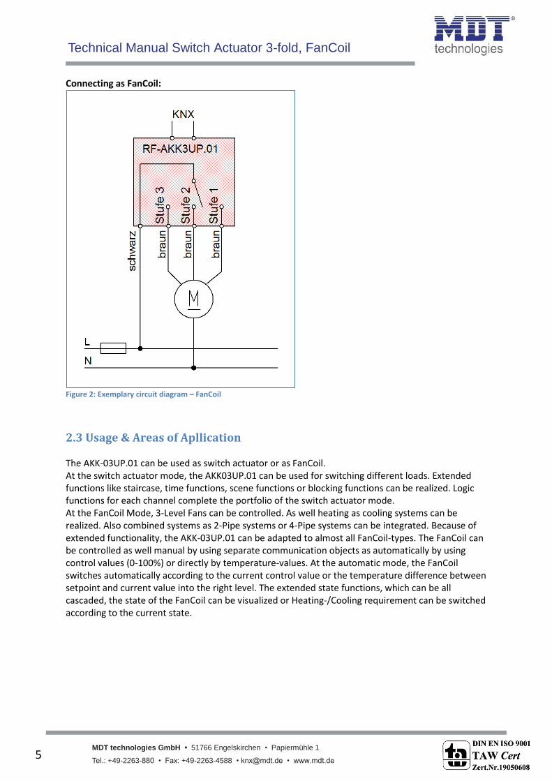
Connecting as FanCoil:
Figure 2: Exemplary circuit diagram – FanCoil
2.3 Usage & Areas of Apllication The AKK-03UP.01 can be used as switch actuator or as FanCoil. At the switch actuator mode, the AKK03UP.01 can be used for switching different loads. Extended functions like staircase, time functions, scene functions or blocking functions can be realized. Logic functions for each channel complete the portfolio of the switch actuator mode. At the FanCoil Mode, 3-Level Fans can be controlled. As well heating as cooling systems can be realized. Also combined systems as 2-Pipe systems or 4-Pipe systems can be integrated. Because of extended functionality, the AKK-03UP.01 can be adapted to almost all FanCoil-types. The FanCoil can be controlled as well manual by using separate communication objects as automatically by using control values (0-100%) or directly by temperature-values. At the automatic mode, the FanCoil switches automatically according to the current control value or the temperature difference between setpoint and current value into the right level. The extended state functions, which can be all cascaded, the state of the FanCoil can be visualized or Heating-/Cooling requirement can be switched according to the current state.
Technical Manual Switch Actuator 3-fold, FanCoil
MDT technologies GmbH • 51766 Engelskirchen • Papiermühle 1
Tel.: +49-2263-880 • Fax: +49-2263-4588 • [email protected] • www.mdt.de 6
6
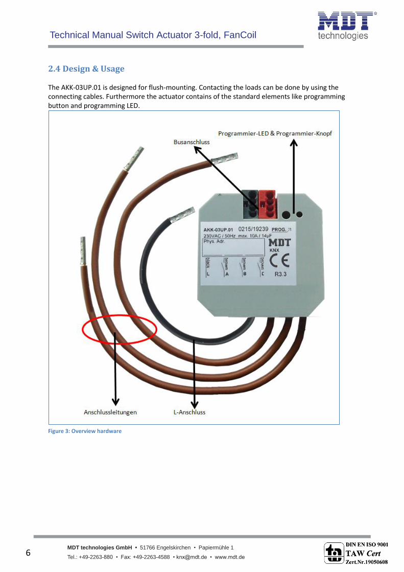
2.4 Design & Usage The AKK-03UP.01 is designed for flush-mounting. Contacting the loads can be done by using the connecting cables. Furthermore the actuator contains of the standard elements like programming button and programming LED.
Figure 3: Overview hardware

Technical Manual Switch Actuator 3-fold, FanCoil
MDT technologies GmbH • 51766 Engelskirchen • Papiermühle 1
Tel.: +49-2263-880 • Fax: +49-2263-4588 • [email protected] • www.mdt.de 7
7
2.5 Setting at the ETS-Software
Selection at the product database: Manufacturer: MDT Technologies Product family: Actuator Product type: Switching, Staircase Medium Type: Twisted Pair (TP) Product name: AKK-03UP.01 Order number: AKK-03UP.01
2.6 Starting Up After wiring the allocation of the physical address and the parameterization of every channel follow:
(1) Connect the interface with the bus, e.g. MDT USB interface (2) set bus power up (3) Press the programming button at the device(red programming LED lights) (4) Loading of the physical address out of the ETS-Software by using the interface(red LED goes
out, as well this process was completed successful) (5) Loading of the application, with requested parameterization (6) If the device is enabled you can test the requested functions(also possible by using the ETS-
Software)

Technical Manual Switch Actuator 3-fold, FanCoil
MDT technologies GmbH • 51766 Engelskirchen • Papiermühle 1 • Tel.: +49-2263-880 • Fax: +49-2263-4588 • [email protected] • www.mdt.de 8
8
3 Communication objects
3.1 Mode: Actuator
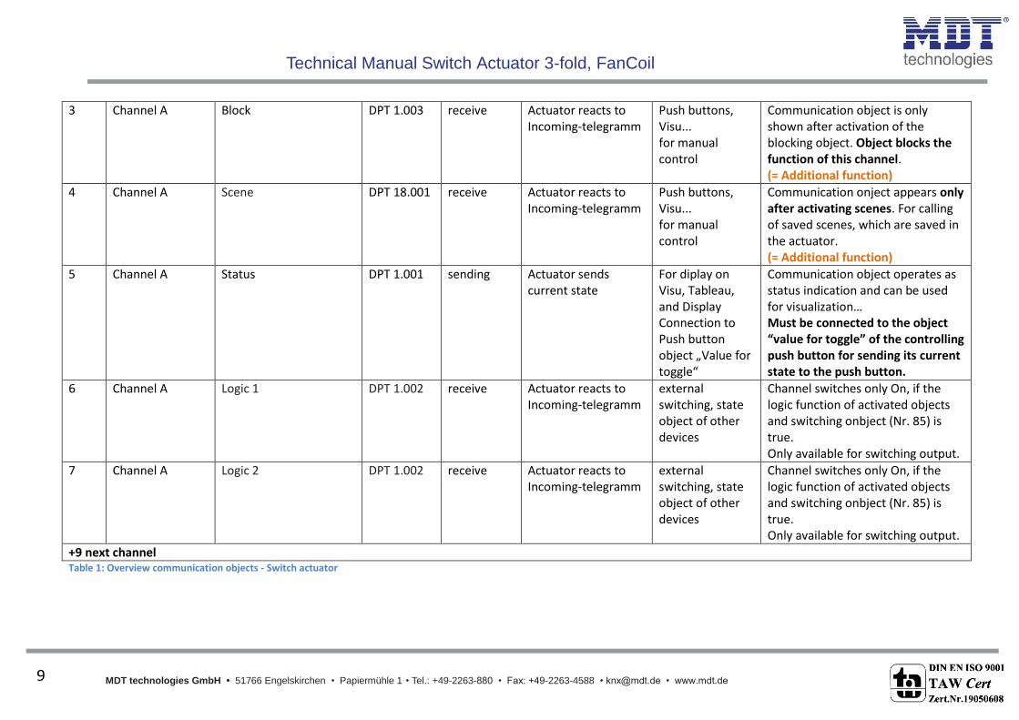
3.1.1 Overview and Usage No. Name Object function Data type Direction Info Usage Tip
General Functions:
45 Central function Switch on/off DPT 1.001 receive Actuator reacts to Incoming-telegramm
Push buttons, Visu... for manual control
Communication object is always shown and enbales the central on/off switching of all channels, which have an enabled central function.
46 Operating Send Status DPT 1.011 send Actuator sends Operating-Telgeram cyclic
Diagnostic Object is shown when the cyclic Operating telegram is set to active.
Functions per channel:
0 Channel A Switch on/off DPT 1.001 receive Actuator reacts to Incoming-telegramm
Push buttons, Visu... for manual control
Communication object is shown at the operating mode „switch“ and controls the channel On/Off, which is normally connected to all control keys. (= Main function at switch)
1 Channel A Staircase DPT 1.001 receive Actuator reacts to Incoming-telegramm
Push buttons, Visu... for manual control
Communication object is shown at the operating mode „switch“ and controls the channel On/Off, which is normally connected to all control keys. The channel switches off again after adjusted time is expired. (= Main function at staircase)
Technical Manual Switch Actuator 3-fold, FanCoil
MDT technologies GmbH • 51766 Engelskirchen • Papiermühle 1 • Tel.: +49-2263-880 • Fax: +49-2263-4588 • [email protected] • www.mdt.de 9
9
3 Channel A Block DPT 1.003 receive Actuator reacts to Incoming-telegramm
Push buttons, Visu... for manual control
Communication object is only shown after activation of the blocking object. Object blocks the function of this channel. (= Additional function)
4 Channel A Scene DPT 18.001 receive Actuator reacts to Incoming-telegramm
Push buttons, Visu... for manual control
Communication onject appears only after activating scenes. For calling of saved scenes, which are saved in the actuator. (= Additional function)
5 Channel A Status DPT 1.001 sending Actuator sends current state
For diplay on Visu, Tableau, and Display Connection to Push button object „Value for toggle“
Communication object operates as status indication and can be used for visualization… Must be connected to the object “value for toggle” of the controlling push button for sending its current state to the push button.
6 Channel A Logic 1 DPT 1.002 receive Actuator reacts to Incoming-telegramm
external switching, state object of other devices
Channel switches only On, if the logic function of activated objects and switching onbject (Nr. 85) is true. Only available for switching output.
7 Channel A Logic 2 DPT 1.002 receive Actuator reacts to Incoming-telegramm
external switching, state object of other devices
Channel switches only On, if the logic function of activated objects and switching onbject (Nr. 85) is true. Only available for switching output.
+9 next channel Table 1: Overview communication objects - Switch actuator
Technical Manual Switch Actuator 3-fold, FanCoil
MDT technologies GmbH • 51766 Engelskirchen • Papiermühle 1
Tel.: +49-2263-880 • Fax: +49-2263-4588 • [email protected] • www.mdt.de 10
10
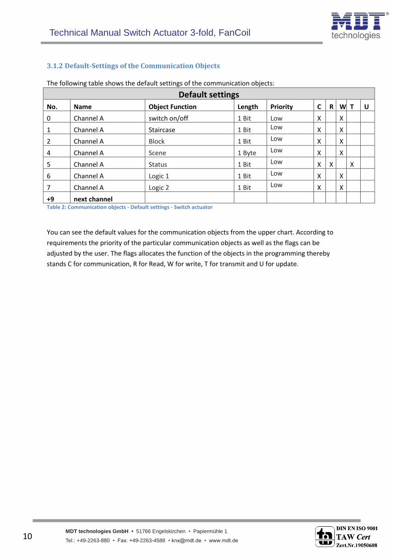
3.1.2 Default-Settings of the Communication Objects The following table shows the default settings of the communication objects:
Default settings No. Name Object Function Length Priority C R W T U
0 Channel A switch on/off 1 Bit Low X X
1 Channel A Staircase 1 Bit Low X X
2 Channel A Block 1 Bit Low X X
4 Channel A Scene 1 Byte Low X X
5 Channel A Status 1 Bit Low X X X
6 Channel A Logic 1 1 Bit Low X X
7 Channel A Logic 2 1 Bit Low X X
+9 next channel Table 2: Communication objects - Default settings - Switch actuator
You can see the default values for the communication objects from the upper chart. According to
requirements the priority of the particular communication objects as well as the flags can be
adjusted by the user. The flags allocates the function of the objects in the programming thereby
stands C for communication, R for Read, W for write, T for transmit and U for update.
Technical Manual Switch Actuator 3-fold, FanCoil
MDT technologies GmbH • 51766 Engelskirchen • Papiermühle 1 • Tel.: +49-2263-880 • Fax: +49-2263-4588 • [email protected] • www.mdt.de
11
11
3.2 Mode: FanCoil
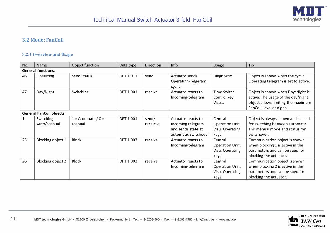
3.2.1 Overview and Usage
No. Name Object function Data type Direction Info Usage Tip
General functions:
46 Operating Send Status DPT 1.011 send Actuator sends Operating-Telgeram cyclic
Diagnostic Object is shown when the cyclic Operating telegram is set to active.
47 Day/Night Switching DPT 1.001 receive Actuator reacts to Incoming-telegram
Time Switch, Control key, Visu…
Object is shown when Day/Night is active. The usage of the day/night object allows limiting the maximum FanCoil Level at night.
General FanCoil objects:
1 Switching Auto/Manual
1 = Automatic/ 0 = Manual
DPT 1.001 send/ receicve
Actuator reacts to Incoming telegram and sends state at automatic switchover
Central Operation Unit, Visu, Operating keys
Object is always shown and is used for switching between automatic and manual mode and status for switchover.
25 Blocking object 1 Block DPT 1.003 receive Actuator reacts to Incoming-telegram
Central Operation Unit, Visu, Operating keys
Communication object is shown when blocking 1 is active in the parameters and can be sued for blocking the actuator.
26 Blocking object 2 Block DPT 1.003 receive Actuator reacts to Incoming-telegram
Central Operation Unit, Visu, Operating keys
Communication object is shown when blocking 2 is active in the parameters and can be sued for blocking the actuator.
Technical Manual Switch Actuator 3-fold, FanCoil
MDT technologies GmbH • 51766 Engelskirchen • Papiermühle 1 • Tel.: +49-2263-880 • Fax: +49-2263-4588 • [email protected] • www.mdt.de
12
12
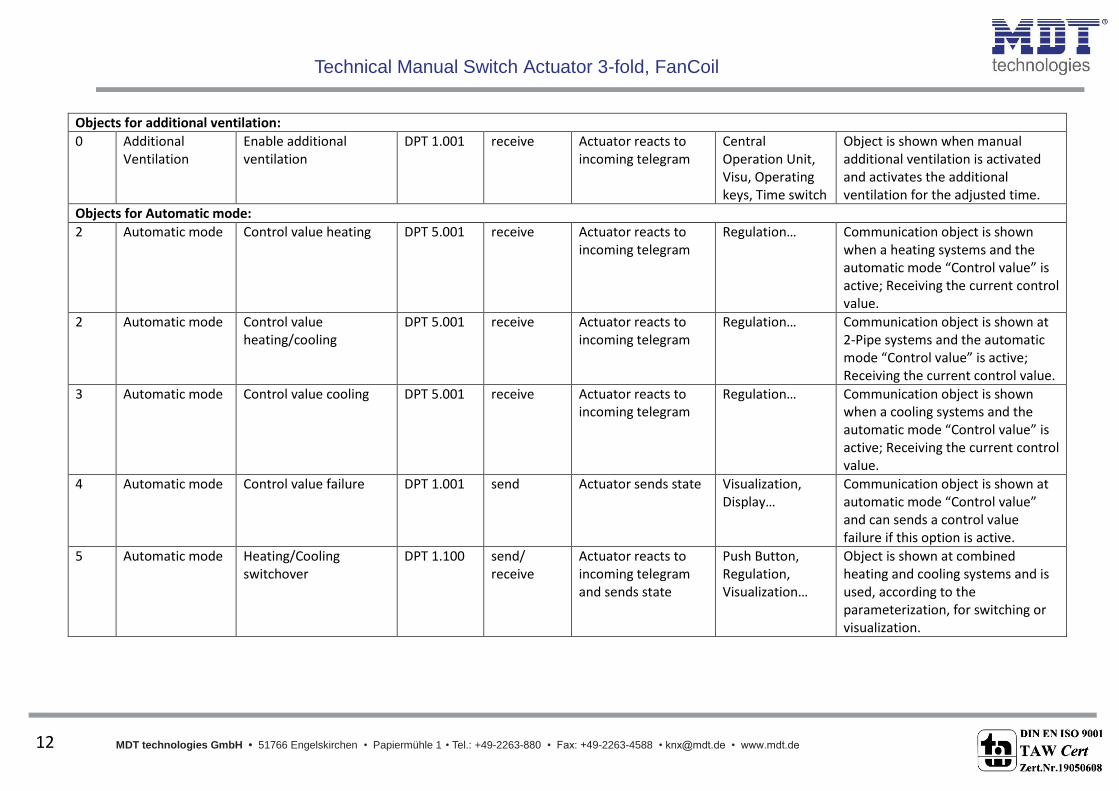
Objects for additional ventilation:
0 Additional Ventilation
Enable additional ventilation
DPT 1.001 receive Actuator reacts to incoming telegram
Central Operation Unit, Visu, Operating keys, Time switch
Object is shown when manual additional ventilation is activated and activates the additional ventilation for the adjusted time.
Objects for Automatic mode:
2 Automatic mode Control value heating DPT 5.001 receive Actuator reacts to incoming telegram
Regulation… Communication object is shown when a heating systems and the automatic mode “Control value” is active; Receiving the current control value.
2 Automatic mode Control value heating/cooling
DPT 5.001 receive Actuator reacts to incoming telegram
Regulation… Communication object is shown at 2-Pipe systems and the automatic mode “Control value” is active; Receiving the current control value.
3 Automatic mode Control value cooling DPT 5.001 receive Actuator reacts to incoming telegram
Regulation… Communication object is shown when a cooling systems and the automatic mode “Control value” is active; Receiving the current control value.
4 Automatic mode Control value failure DPT 1.001 send Actuator sends state Visualization, Display…
Communication object is shown at automatic mode “Control value” and can sends a control value failure if this option is active.
5 Automatic mode Heating/Cooling switchover
DPT 1.100 send/ receive
Actuator reacts to incoming telegram and sends state
Push Button, Regulation, Visualization…
Object is shown at combined heating and cooling systems and is used, according to the parameterization, for switching or visualization.

Technical Manual Switch Actuator 3-fold, FanCoil
MDT technologies GmbH • 51766 Engelskirchen • Papiermühle 1 • Tel.: +49-2263-880 • Fax: +49-2263-4588 • [email protected] • www.mdt.de
13
13
6 Automatic mode Switch heating valve DPT 1.001 send Actuator sends switching telegram
separate switching channel for switching the heating valve of the FanCoil-system
Object is always shown when heating mode is active.
7 Automatic mode Switch cooling valve DPT 1.001 send Actuator sends switching telegram
separate switching channel for switching the cooling valve of the FanCoil-system
Object is always shown when cooling mode is active.
8 Automatic mode Manual setpoint offset DPT 1.007 receive Actuator reacts to incoming telegram
Central operation unit, Visu, Push Button…
Object can be activated at automatic mode “Delta T”
27 Automatic mode Temperature value DPT 9.001 receive Actuator reacts to incoming telegram
Temperature-sensor
Object is always shown at automatic mode “Delta T” and is used for receiving the current temperature.
28 Automatic mode Setoint temperature DPT 9.001 receive Actuator reacts to incoming telegram
Central operation unit, Visu, Push Button…
Object is always shown at automatic mode “Delta T” and is used for receiving a new setpoint.
29 Automatic mode Setpoint offset DPT 9.002 receive Actuator reacts to incoming telegram
Central operation unit, Visu, Push Button…
Object can be activated at automatic mode “Delta T” and is used for receiving a setpoint offset.
30 Automatic mode Current setpoint temperature
DPT 9.001 send Actuator sends state Visualization… Object is always shown at automatic mode “Delta T” and is used for visualization the current setpoint.
Technical Manual Switch Actuator 3-fold, FanCoil
MDT technologies GmbH • 51766 Engelskirchen • Papiermühle 1 • Tel.: +49-2263-880 • Fax: +49-2263-4588 • [email protected] • www.mdt.de
14
14
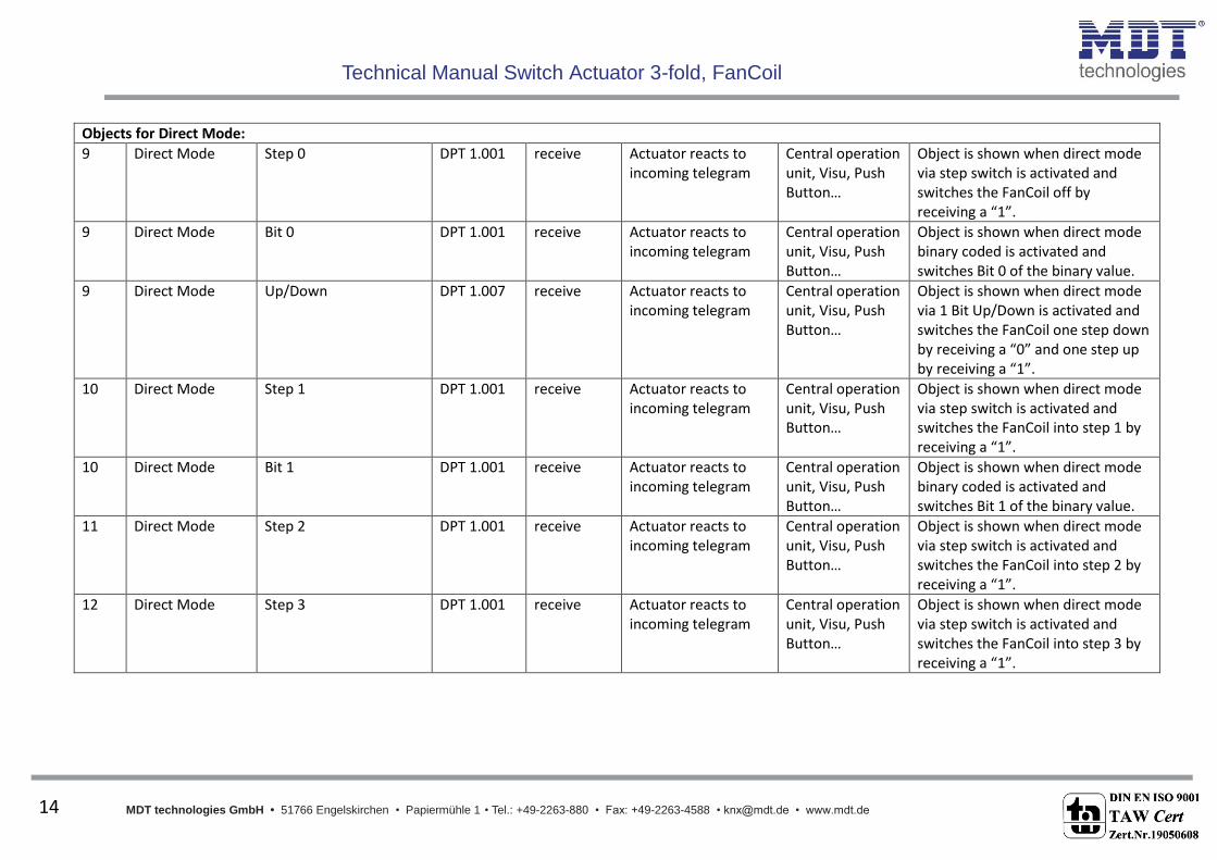
Objects for Direct Mode:
9 Direct Mode Step 0 DPT 1.001 receive Actuator reacts to incoming telegram
Central operation unit, Visu, Push Button…
Object is shown when direct mode via step switch is activated and switches the FanCoil off by receiving a “1”.
9 Direct Mode Bit 0 DPT 1.001 receive Actuator reacts to incoming telegram
Central operation unit, Visu, Push Button…
Object is shown when direct mode binary coded is activated and switches Bit 0 of the binary value.
9 Direct Mode Up/Down DPT 1.007 receive Actuator reacts to incoming telegram
Central operation unit, Visu, Push Button…
Object is shown when direct mode via 1 Bit Up/Down is activated and switches the FanCoil one step down by receiving a “0” and one step up by receiving a “1”.
10 Direct Mode Step 1 DPT 1.001 receive Actuator reacts to incoming telegram
Central operation unit, Visu, Push Button…
Object is shown when direct mode via step switch is activated and switches the FanCoil into step 1 by receiving a “1”.
10 Direct Mode Bit 1 DPT 1.001 receive Actuator reacts to incoming telegram
Central operation unit, Visu, Push Button…
Object is shown when direct mode binary coded is activated and switches Bit 1 of the binary value.
11 Direct Mode Step 2 DPT 1.001 receive Actuator reacts to incoming telegram
Central operation unit, Visu, Push Button…
Object is shown when direct mode via step switch is activated and switches the FanCoil into step 2 by receiving a “1”.
12 Direct Mode Step 3 DPT 1.001 receive Actuator reacts to incoming telegram
Central operation unit, Visu, Push Button…
Object is shown when direct mode via step switch is activated and switches the FanCoil into step 3 by receiving a “1”.
Technical Manual Switch Actuator 3-fold, FanCoil
MDT technologies GmbH • 51766 Engelskirchen • Papiermühle 1 • Tel.: +49-2263-880 • Fax: +49-2263-4588 • [email protected] • www.mdt.de
15
15
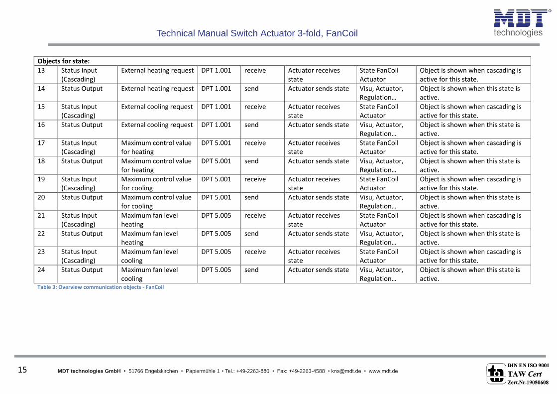
Objects for state:
13 Status Input (Cascading)
External heating request DPT 1.001 receive Actuator receives state
State FanCoil Actuator
Object is shown when cascading is active for this state.
14 Status Output External heating request DPT 1.001 send Actuator sends state Visu, Actuator, Regulation…
Object is shown when this state is active.
15 Status Input (Cascading)
External cooling request DPT 1.001 receive Actuator receives state
State FanCoil Actuator
Object is shown when cascading is active for this state.
16 Status Output External cooling request DPT 1.001 send Actuator sends state Visu, Actuator, Regulation…
Object is shown when this state is active.
17 Status Input (Cascading)
Maximum control value for heating
DPT 5.001 receive Actuator receives state
State FanCoil Actuator
Object is shown when cascading is active for this state.
18 Status Output Maximum control value for heating
DPT 5.001 send Actuator sends state Visu, Actuator, Regulation…
Object is shown when this state is active.
19 Status Input (Cascading)
Maximum control value for cooling
DPT 5.001 receive Actuator receives state
State FanCoil Actuator
Object is shown when cascading is active for this state.
20 Status Output Maximum control value for cooling
DPT 5.001 send Actuator sends state Visu, Actuator, Regulation…
Object is shown when this state is active.
21 Status Input (Cascading)
Maximum fan level heating
DPT 5.005 receive Actuator receives state
State FanCoil Actuator
Object is shown when cascading is active for this state.
22 Status Output Maximum fan level heating
DPT 5.005 send Actuator sends state Visu, Actuator, Regulation…
Object is shown when this state is active.
23 Status Input (Cascading)
Maximum fan level cooling
DPT 5.005 receive Actuator receives state
State FanCoil Actuator
Object is shown when cascading is active for this state.
24 Status Output Maximum fan level cooling
DPT 5.005 send Actuator sends state Visu, Actuator, Regulation…
Object is shown when this state is active.
Table 3: Overview communication objects - FanCoil

Technical Manual Switch Actuator 3-fold, FanCoil
MDT technologies GmbH • 51766 Engelskirchen • Papiermühle 1
Tel.: +49-2263-880 • Fax: +49-2263-4588 • [email protected] • www.mdt.de 16
16
3.2.2 Default settings of the communication objects The following table shows the default settings of the communication objects:
Default settings No. Name Object Function Length Priority C R W T U 0 Additional
ventilation Enable additional ventilation
1 Bit Low X X
1 Switching Auto/Manual
1 = Automatic/ 0 = Manual
1 Bit Low X X X X X
2 Automatic mode Control value heating 1 Byte Low X X
2 Automatic mode Control value heating/cooling
1 Byte Low X X
3 Automatic mode Control value cooling 1 Byte Low X X
4 Automatic mode Control value failure 1 Bit Low X X X
5 Automatic mode Heating/Cooling switchover
1 Bit Low X X X X X
6 Automatic mode Switch heating valve 1 Bit Low X X X
7 Automatic mode Switch cooling valve 1 Bit Low X X X
8 Automatic mode Manual setpoint offset 1 Bit Low X X
9 Direktbetrieb Step 0 1 Bit Low X X
9 Direktbetrieb Bit 0 1 Bit Low X X
9 Direktbetrieb Up/Down 1 Bit Low X X
10 Direktbetrieb Step 1 1 Bit Low X X
10 Direktbetrieb Bit 1 1 Bit Low X X
11 Direktbetrieb Step 2 1 Bit Low X X
12 Direktbetrieb Step 3 1 Bit Low X X
13 Status Input (Cascading)
External heating request
1 Bit Low X X
14 Status Output External heating request
1 Bit Low X X X
15 Status Input (Cascading)
External cooling request 1 Bit Low X X
16 Status Output External cooling request 1 Bit Low X X X
17 Status Input (Cascading)
Maximum control value for heating
1 Byte Low X X
18 Status Output Maximum control value for heating
1 Byte Low X X X
19 Status Input (Cascading)
Maximum control value for cooling
1 Byte Low X X
20 Status Output Maximum control value for cooling
1 Byte Low X X X
21 Status Input (Cascading)
Maximum fan level heating
1 Byte Low X X
22 Status Output Maximum fan level heating
1 Byte Low X X X
23 Status Input (Cascading)
Maximum fan level cooling
1 Byte Low X X
Technical Manual Switch Actuator 3-fold, FanCoil
MDT technologies GmbH • 51766 Engelskirchen • Papiermühle 1
Tel.: +49-2263-880 • Fax: +49-2263-4588 • [email protected] • www.mdt.de 17
17
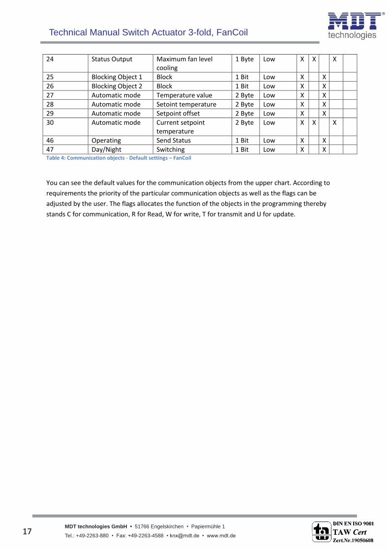
24 Status Output Maximum fan level cooling
1 Byte Low X X X
25 Blocking Object 1 Block 1 Bit Low X X
26 Blocking Object 2 Block 1 Bit Low X X
27 Automatic mode Temperature value 2 Byte Low X X
28 Automatic mode Setoint temperature 2 Byte Low X X
29 Automatic mode Setpoint offset 2 Byte Low X X
30 Automatic mode Current setpoint temperature
2 Byte Low X X X
46 Operating Send Status 1 Bit Low X X
47 Day/Night Switching 1 Bit Low X X Table 4: Communication objects - Default settings – FanCoil
You can see the default values for the communication objects from the upper chart. According to
requirements the priority of the particular communication objects as well as the flags can be
adjusted by the user. The flags allocates the function of the objects in the programming thereby
stands C for communication, R for Read, W for write, T for transmit and U for update.
Technical Manual Switch Actuator 3-fold, FanCoil
MDT technologies GmbH • 51766 Engelskirchen • Papiermühle 1
Tel.: +49-2263-880 • Fax: +49-2263-4588 • [email protected] • www.mdt.de 18
18
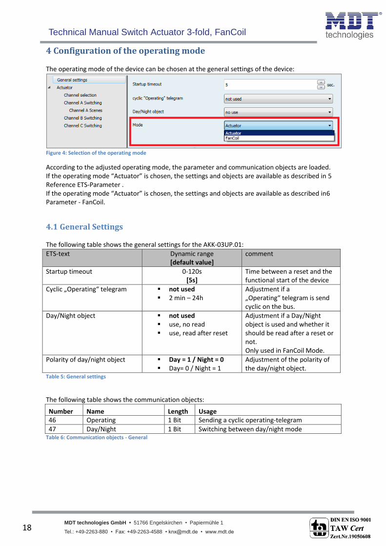
4 Configuration of the operating mode The operating mode of the device can be chosen at the general settings of the device:
Figure 4: Selection of the operating mode
According to the adjusted operating mode, the parameter and communication objects are loaded. If the operating mode “Actuator” is chosen, the settings and objects are available as described in 5 Reference ETS-Parameter . If the operating mode “Actuator” is chosen, the settings and objects are available as described in6 Parameter - FanCoil.
4.1 General Settings The following table shows the general settings for the AKK-03UP.01:
ETS-text Dynamic range [default value]
comment
Startup timeout 0-120s [5s]
Time between a reset and the functional start of the device
Cyclic „Operating“ telegram not used 2 min – 24h
Adjustment if a „Operating“ telegram is send cyclic on the bus.
Day/Night object not used use, no read use, read after reset
Adjustment if a Day/Night object is used and whether it should be read after a reset or not. Only used in FanCoil Mode.
Polarity of day/night object Day = 1 / Night = 0 Day= 0 / Night = 1
Adjustment of the polarity of the day/night object.
Table 5: General settings
The following table shows the communication objects:
Number Name Length Usage 46 Operating 1 Bit Sending a cyclic operating-telegram
47 Day/Night 1 Bit Switching between day/night mode Table 6: Communication objects - General

Technical Manual Switch Actuator 3-fold, FanCoil
MDT technologies GmbH • 51766 Engelskirchen • Papiermühle 1
Tel.: +49-2263-880 • Fax: +49-2263-4588 • [email protected] • www.mdt.de 19
19
5 Reference ETS-Parameter - Actuator
5.1 Channel selection
Every channel can be selected as Switch or as Staircase function at the sub menu Channel Selection. According to this setting, further settings are shown:
Figure 5: Channel Selection

Technical Manual Switch Actuator 3-fold, FanCoil
MDT technologies GmbH • 51766 Engelskirchen • Papiermühle 1
Tel.: +49-2263-880 • Fax: +49-2263-4588 • [email protected] • www.mdt.de 20
20
5.2 Identical parameter The following parameters, which are described at the headings 5.2.x, are as well available at channels selected as switch as at channels selected as staircase.
5.2.1 Relay operating mode The following illustration shows the setting options for this parameter:
Figure 6: Operating mode
The following chart shows the dynamic range for this parameter:
ETS-text Dynamic range [default value]
comment
Mode normally opened normally closed
Relay operating mode of the channel
Table 7: Operating mode
The following diagram shows the behavior of the relay operating mode normally closed and normally opened. The input for the channels is a KNX-telegram, which sends alternating 0-signals and 1-signals:

Technical Manual Switch Actuator 3-fold, FanCoil
MDT technologies GmbH • 51766 Engelskirchen • Papiermühle 1
Tel.: +49-2263-880 • Fax: +49-2263-4588 • [email protected] • www.mdt.de 21
21
5.2.2 Central function The following illustration shows the setting options at the ETS-Software:
Figure 7: Central function
The following chart shows the dynamic range for this parameter:
ETS-text Dynamic range [default value]
comment
Central function not active active
switches the central function on/off for this channel
Table 8: Central function
The central function can be switched on/off for every channel. For switching on this function, you have to choose the option “active”. By calling the central communication object, all channels with an activated central function are switched on with their current parameterization. So switch-on delays or staircase functions are still kept. The central function can make programming much more easier and your project can become more clear. The following chart shows the associated communication object:
Number Name Length Usage 45 Central function 1 Bit central switching of the channels
number depends to the number of channels Table 9: Communication object central function
5.2.3 Behavior at block/unblock The following illustration shows the setting options at the ETS-Software:
Figure 8: Blocking function
The following chart shows the dynamic range for this parameter:
ETS-text Dynamic range [default value]
comment
Behavior when locked Behavior when unlocked
On Off no change
Behavior to a blocking/unblocking process
Table 10: Behavior at block/unblock
Technical Manual Switch Actuator 3-fold, FanCoil
MDT technologies GmbH • 51766 Engelskirchen • Papiermühle 1
Tel.: +49-2263-880 • Fax: +49-2263-4588 • [email protected] • www.mdt.de 22
22
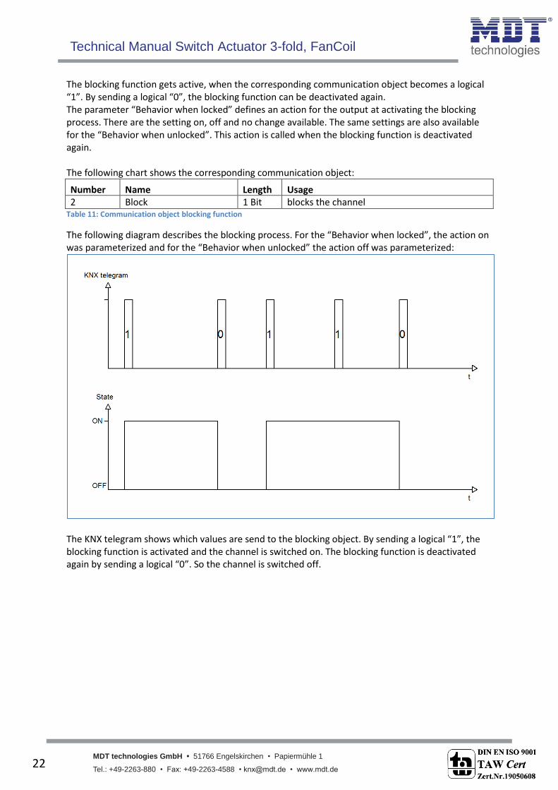
The blocking function gets active, when the corresponding communication object becomes a logical “1”. By sending a logical “0”, the blocking function can be deactivated again. The parameter “Behavior when locked” defines an action for the output at activating the blocking process. There are the setting on, off and no change available. The same settings are also available for the “Behavior when unlocked”. This action is called when the blocking function is deactivated again. The following chart shows the corresponding communication object:
Number Name Length Usage 2 Block 1 Bit blocks the channel
Table 11: Communication object blocking function
The following diagram describes the blocking process. For the “Behavior when locked”, the action on was parameterized and for the “Behavior when unlocked” the action off was parameterized:
The KNX telegram shows which values are send to the blocking object. By sending a logical “1”, the blocking function is activated and the channel is switched on. The blocking function is deactivated again by sending a logical “0”. So the channel is switched off.

Technical Manual Switch Actuator 3-fold, FanCoil
MDT technologies GmbH • 51766 Engelskirchen • Papiermühle 1
Tel.: +49-2263-880 • Fax: +49-2263-4588 • [email protected] • www.mdt.de 23
23
5.3 Switching output The following parameters, which are described at the headings 4.3.x, are only available at channels selected as switch.
5.3.1 Overview By choosing a channel as switch, a sub menu, called Channel A Switching, appears for this channel at the left drop down menu. The sub menu is shown at the following illustration:
Figure 9: Switching output
Technical Manual Switch Actuator 3-fold, FanCoil
MDT technologies GmbH • 51766 Engelskirchen • Papiermühle 1
Tel.: +49-2263-880 • Fax: +49-2263-4588 • [email protected] • www.mdt.de 24
24
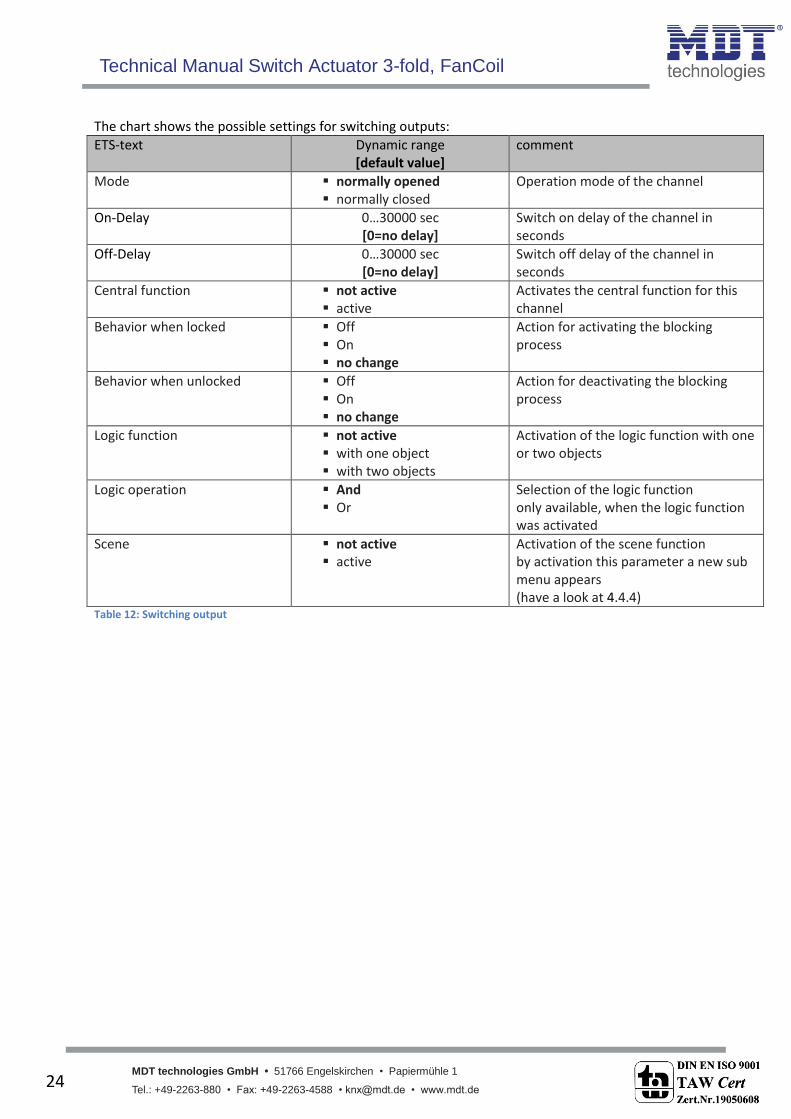
The chart shows the possible settings for switching outputs:
ETS-text Dynamic range [default value]
comment
Mode normally opened normally closed
Operation mode of the channel
On-Delay 0…30000 sec [0=no delay]
Switch on delay of the channel in seconds
Off-Delay 0…30000 sec [0=no delay]
Switch off delay of the channel in seconds
Central function not active active
Activates the central function for this channel
Behavior when locked Off On no change
Action for activating the blocking process
Behavior when unlocked Off On no change
Action for deactivating the blocking process
Logic function not active with one object with two objects
Activation of the logic function with one or two objects
Logic operation And Or
Selection of the logic function only available, when the logic function was activated
Scene not active active
Activation of the scene function by activation this parameter a new sub menu appears (have a look at 4.4.4)
Table 12: Switching output

Technical Manual Switch Actuator 3-fold, FanCoil
MDT technologies GmbH • 51766 Engelskirchen • Papiermühle 1
Tel.: +49-2263-880 • Fax: +49-2263-4588 • [email protected] • www.mdt.de 25
25
5.3.2 On-/Off-delay The following illustration shows the setting options at the ETS-Software:
Figure 10: On/Off delay
The on-delay causes a delayed switch of the channel. At sending an on-signal to the channel, first the adjusted on delay time expires and afterwards the channel will be switched on. The off delay works on the same principle. At sending an off-signal, first the adjusted off delay time expires and afterwards the channel will be switched off. Both functions work as well alone as combined. By adjusting “0 seconds” for a delay the function is switched off. The following diagram describes the combination of on and off delay:

Technical Manual Switch Actuator 3-fold, FanCoil
MDT technologies GmbH • 51766 Engelskirchen • Papiermühle 1
Tel.: +49-2263-880 • Fax: +49-2263-4588 • [email protected] • www.mdt.de 26
26
5.3.3 Logical functions The following illustration shows the setting options at the ETS-Software:
Figure 11: Logical functions
The logic function can be activated with one or two objects. The objects are the inputs of the logic block. Furthermore you can choose between an AND-function and an OR-function. The following figure shows an overview of the basic logic function with two objects:
Figure 12: Overview Logic function
The logic function consists of the activated input objects and the switching object for each channel. The output of the logic is the respective relay output of the channel, so the physical switching of the channel. The following chart shows the relevant communication objects:
Number Name Length Usage 5 Logic 1 1 Bit Logic object 1, is the first input for the logic
block
6 Logic 2 1 Bit Logic object 2, is the second input for the logic block
Table 13: Communication objects logic
Technical Manual Switch Actuator 3-fold, FanCoil
MDT technologies GmbH • 51766 Engelskirchen • Papiermühle 1
Tel.: +49-2263-880 • Fax: +49-2263-4588 • [email protected] • www.mdt.de 27
27
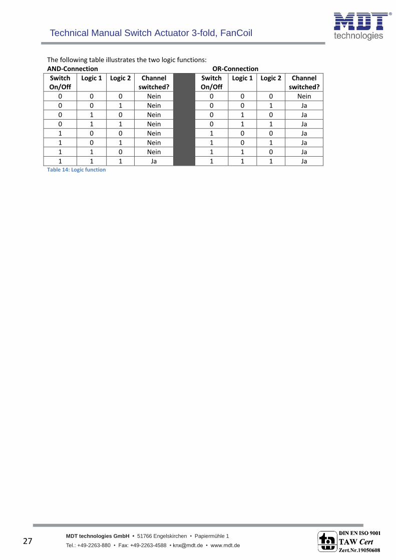
The following table illustrates the two logic functions: AND-Connection OR-Connection
Switch On/Off
Logic 1 Logic 2 Channel switched?
Switch On/Off
Logic 1 Logic 2 Channel switched?
0 0 0 Nein 0 0 0 Nein
0 0 1 Nein 0 0 1 Ja
0 1 0 Nein 0 1 0 Ja
0 1 1 Nein 0 1 1 Ja
1 0 0 Nein 1 0 0 Ja
1 0 1 Nein 1 0 1 Ja
1 1 0 Nein 1 1 0 Ja
1 1 1 Ja 1 1 1 Ja Table 14: Logic function

Technical Manual Switch Actuator 3-fold, FanCoil
MDT technologies GmbH • 51766 Engelskirchen • Papiermühle 1
Tel.: +49-2263-880 • Fax: +49-2263-4588 • [email protected] • www.mdt.de 28
28
5.3.4 Scene function When functions of different groups (e.g. light, heating and shutter) shall be changed simultaneously with only one keystroke, it is practical to use the scene function. By calling a scene, you can switch the lights to a specific value, drive the shutter to an absolute position, switch the heating to the day mode and switch the power supply of the sockets on. The telegrams of these functions can have as well different formats as different values with different meaning (e.g. “0” for switch the lights off and open the shutters). If there were no scene function, you would have to send a single telegram for every actuator to get the same function. The scene function of the switch actuator enables you to connect the channels of the switch actuator to a scene control. For that, you have to assign the value to the appropriated space (scene A..H). It is possible to program up to 8 scenes per switching output. When you activate the scene function at the switching output, a new sub menu for the scenes appears at the left drop down menu. There are settings to activate single scenes, set values and scene numbers and switch the memory function on/off at this sub menu. Scenes are activated by receiving their scene numbers at the communication object for the scenes. If the memory function of the scenes is activated, the current value of the channel will be saved at the called scene number. The communication objects of the scenes have always the length of 1 byte. The following illustration shows the setting options at the ETS-Software for activating the scene function:
Figure 13: Scene function
The following chart shows the relevant communication object:
Number Name Length Usage 3 Scene 1 Byte Call of the scene
Table 15: Communication object scene
For calling a certain scene, you have to send the value for the scene to the communication object. The value of the scene number is always one number less than the adjusted scene number. For calling scene 1, you have to send a “0”. So the scene numbers have the numbers from 1 to 64, but the values for the scenes only from 0 to 63. If you want to call scenes by a binary input or another KNX device, you have to set the same number at the calling device as at the receiving device. The calling device, e.g. a binary input, sends automatically the right value for calling the scene.
Technical Manual Switch Actuator 3-fold, FanCoil
MDT technologies GmbH • 51766 Engelskirchen • Papiermühle 1
Tel.: +49-2263-880 • Fax: +49-2263-4588 • [email protected] • www.mdt.de 29
29
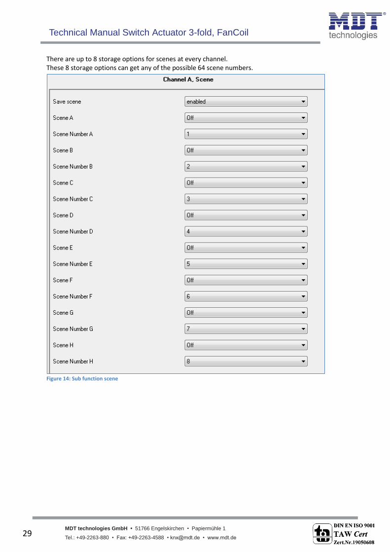
There are up to 8 storage options for scenes at every channel. These 8 storage options can get any of the possible 64 scene numbers.
Figure 14: Sub function scene
Technical Manual Switch Actuator 3-fold, FanCoil
MDT technologies GmbH • 51766 Engelskirchen • Papiermühle 1
Tel.: +49-2263-880 • Fax: +49-2263-4588 • [email protected] • www.mdt.de 30
30
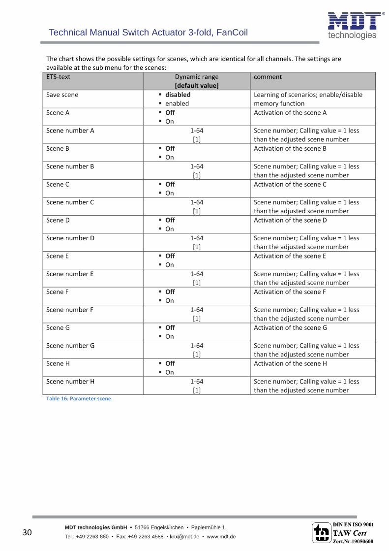
The chart shows the possible settings for scenes, which are identical for all channels. The settings are available at the sub menu for the scenes:
ETS-text Dynamic range [default value]
comment
Save scene disabled enabled
Learning of scenarios; enable/disable memory function
Scene A Off On
Activation of the scene A
Scene number A 1-64 [1]
Scene number; Calling value = 1 less than the adjusted scene number
Scene B Off On
Activation of the scene B
Scene number B 1-64 [1]
Scene number; Calling value = 1 less than the adjusted scene number
Scene C Off On
Activation of the scene C
Scene number C 1-64 [1]
Scene number; Calling value = 1 less than the adjusted scene number
Scene D Off On
Activation of the scene D
Scene number D 1-64 [1]
Scene number; Calling value = 1 less than the adjusted scene number
Scene E Off On
Activation of the scene E
Scene number E 1-64 [1]
Scene number; Calling value = 1 less than the adjusted scene number
Scene F Off On
Activation of the scene F
Scene number F 1-64 [1]
Scene number; Calling value = 1 less than the adjusted scene number
Scene G Off On
Activation of the scene G
Scene number G 1-64 [1]
Scene number; Calling value = 1 less than the adjusted scene number
Scene H Off On
Activation of the scene H
Scene number H 1-64 [1]
Scene number; Calling value = 1 less than the adjusted scene number
Table 16: Parameter scene
Technical Manual Switch Actuator 3-fold, FanCoil
MDT technologies GmbH • 51766 Engelskirchen • Papiermühle 1
Tel.: +49-2263-880 • Fax: +49-2263-4588 • [email protected] • www.mdt.de 31
31
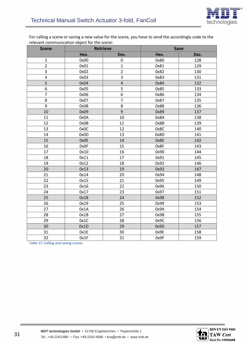
For calling a scene or saving a new value for the scene, you have to send the accordingly code to the relevant communication object for the scene:
Scene Retrieve Save Hex. Dez. Hex. Dez.
1 0x00 0 0x80 128
2 0x01 1 0x81 129
3 0x02 2 0x82 130
4 0x03 3 0x83 131
5 0x04 4 0x84 132
6 0x05 5 0x85 133
7 0x06 6 0x86 134
8 0x07 7 0x87 135
9 0x08 8 0x88 136
10 0x09 9 0x89 137
11 0x0A 10 0x8A 138
12 0x0B 11 0x8B 139
13 0x0C 12 0x8C 140
14 0x0D 13 0x8D 141
15 0x0E 14 0x8E 142
16 0x0F 15 0x8F 143
17 0x10 16 0x90 144
18 0x11 17 0x91 145
19 0x12 18 0x92 146
20 0x13 19 0x93 147
21 0x14 20 0x94 148
22 0x15 21 0x95 149
23 0x16 22 0x96 150
24 0x17 23 0x97 151
25 0x18 24 0x98 152
26 0x19 25 0x99 153
27 0x1A 26 0x9A 154
28 0x1B 27 0x9B 155
29 0x1C 28 0x9C 156
30 0x1D 29 0x9D 157
31 0x1E 30 0x9E 158
32 0x1F 31 0x9F 159 Table 17: Calling and saving scenes
Technical Manual Switch Actuator 3-fold, FanCoil
MDT technologies GmbH • 51766 Engelskirchen • Papiermühle 1
Tel.: +49-2263-880 • Fax: +49-2263-4588 • [email protected] • www.mdt.de 32
32
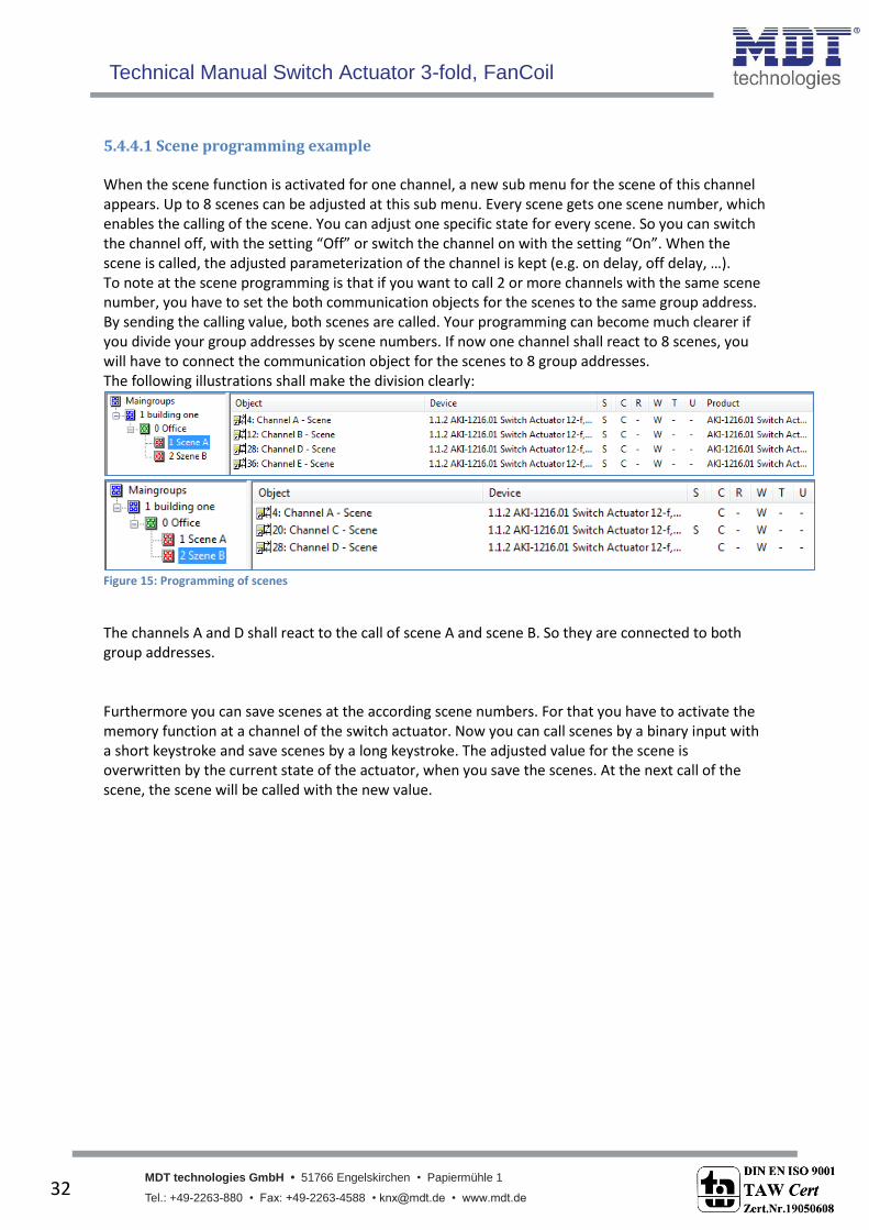
5.4.4.1 Scene programming example When the scene function is activated for one channel, a new sub menu for the scene of this channel appears. Up to 8 scenes can be adjusted at this sub menu. Every scene gets one scene number, which enables the calling of the scene. You can adjust one specific state for every scene. So you can switch the channel off, with the setting “Off” or switch the channel on with the setting “On”. When the scene is called, the adjusted parameterization of the channel is kept (e.g. on delay, off delay, …). To note at the scene programming is that if you want to call 2 or more channels with the same scene number, you have to set the both communication objects for the scenes to the same group address. By sending the calling value, both scenes are called. Your programming can become much clearer if you divide your group addresses by scene numbers. If now one channel shall react to 8 scenes, you will have to connect the communication object for the scenes to 8 group addresses. The following illustrations shall make the division clearly:
Figure 15: Programming of scenes
The channels A and D shall react to the call of scene A and scene B. So they are connected to both group addresses. Furthermore you can save scenes at the according scene numbers. For that you have to activate the memory function at a channel of the switch actuator. Now you can call scenes by a binary input with a short keystroke and save scenes by a long keystroke. The adjusted value for the scene is overwritten by the current state of the actuator, when you save the scenes. At the next call of the scene, the scene will be called with the new value.
Technical Manual Switch Actuator 3-fold, FanCoil
MDT technologies GmbH • 51766 Engelskirchen • Papiermühle 1
Tel.: +49-2263-880 • Fax: +49-2263-4588 • [email protected] • www.mdt.de 33
33
5.4 Staircase The following parameters, which are described at the headings 4.4.x, are only available at channels selected as staircase.
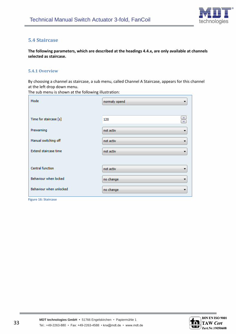
5.4.1 Overview By choosing a channel as staircase, a sub menu, called Channel A Staircase, appears for this channel at the left drop down menu. The sub menu is shown at the following illustration:
Figure 16: Staircase

Technical Manual Switch Actuator 3-fold, FanCoil
MDT technologies GmbH • 51766 Engelskirchen • Papiermühle 1
Tel.: +49-2263-880 • Fax: +49-2263-4588 • [email protected] • www.mdt.de 34
34
The chart shows all possible settings for staircase outputs:
ETS-text Dynamic range [default value]
comment
Mode normally opened normally closed
Operation mode of the channel
Time for staircase [s] 0…65535 sec [120 sec]
Duration of the switching process
Prewarning not active active
Activates the prewarning function
Warning time [s] 0…65535 sec [120 sec]
Duration of the warning; Only available when warning is activated
Prewarning time [s] 0…65535 sec [120 sec]
Adjustment, how long the light shall be switched on after the warning; Whole duration of the warning process is the sum of the 3 times: Staircase time, warning and prewarning Only available when warning is activated
Manual switching off not active active
Activation of the manual turn off of the staircase
Extend staircase time not active active
Activation of the extension of the staircase
Central function not active active
Activates the central function for this channel
Behavior when locked Off On no change
Action for activating the blocking process
Behavior when unlocked Off On no change
Action for deactivating the blocking process
Table 18: Parameter staircase
Technical Manual Switch Actuator 3-fold, FanCoil
MDT technologies GmbH • 51766 Engelskirchen • Papiermühle 1
Tel.: +49-2263-880 • Fax: +49-2263-4588 • [email protected] • www.mdt.de 35
35
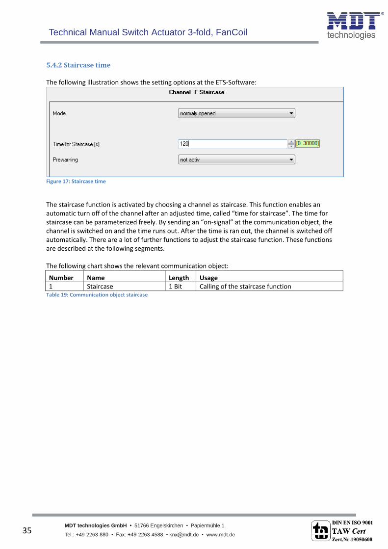
5.4.2 Staircase time The following illustration shows the setting options at the ETS-Software:
Figure 17: Staircase time
The staircase function is activated by choosing a channel as staircase. This function enables an automatic turn off of the channel after an adjusted time, called “time for staircase”. The time for staircase can be parameterized freely. By sending an “on-signal” at the communication object, the channel is switched on and the time runs out. After the time is ran out, the channel is switched off automatically. There are a lot of further functions to adjust the staircase function. These functions are described at the following segments. The following chart shows the relevant communication object:
Number Name Length Usage 1 Staircase 1 Bit Calling of the staircase function
Table 19: Communication object staircase

Technical Manual Switch Actuator 3-fold, FanCoil
MDT technologies GmbH • 51766 Engelskirchen • Papiermühle 1
Tel.: +49-2263-880 • Fax: +49-2263-4588 • [email protected] • www.mdt.de 36
36
5.4.3 Prewarning und Warning The following illustration shows the setting options at the ETS-Software:
Figure 18: Warning timer & prewarning time
The warning function can be activated by adjusting the parameter “Prewarning” as active. Now, you can adjust warning time and prewarning time. The warning function is for warning that the staircase time ran almost out and the lights are switched off soon. This warning happens trough a short turn off the lights. The duration of the turn off is indicated by the warning time. A value of 1-3s is advisable for this parameter. When the warning time runs out, the lights will be switched on again for the adjusted prewarning time. Now you have the opportunities to extend the staircase time, when this parameter was activated, or leave the staircase. A dynamic programming is advisable for this time. So you can adapt this time to spatial conditions (next switch, length of the staircase, etc.). The whole duration of the switching process is the sum of the 3 times. The following diagram shall make this clear:

Technical Manual Switch Actuator 3-fold, FanCoil
MDT technologies GmbH • 51766 Engelskirchen • Papiermühle 1
Tel.: +49-2263-880 • Fax: +49-2263-4588 • [email protected] • www.mdt.de 37
37
5.4.4 Manual switch off The following illustration shows the setting options at the ETS-Software:
Figure 19: Manual switch off
By activation this function, you can switch the channel off before the staircase time runs out. For switching off the channel, you have to send a logical “0” to the communication object for switching the staircase function (have a look atTable 19: Communication object staircase). When this function is not activated, the channel switches only off after the staircase time runs out.
5.4.5 Extend staircase time The following illustration shows the setting options at the ETS-Software:
Figure 20: Extend staircase time
By activating this function, the staircase time is retriggerable. That means, when the staircase time runs already out to 2/3, you can restart the time by sending a new on-signal to the communication object of the staircase function (have a look atTable 19: Communication object staircase). The following diagram shows the behavior of this parameter:
Technical Manual Switch Actuator 3-fold, FanCoil
MDT technologies GmbH • 51766 Engelskirchen • Papiermühle 1
Tel.: +49-2263-880 • Fax: +49-2263-4588 • [email protected] • www.mdt.de 38
38
6 Parameter - FanCoil
6.1 General Functions
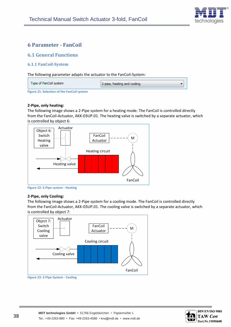
6.1.1 FanCoil-System The following parameter adapts the actuator to the FanCoil-System:
Figure 21: Selection of the FanCoil system
2-Pipe, only heating: The following image shows a 2-Pipe system for a heating mode. The FanCoil is controlled directly from the FanCoil-Actuator, AKK-03UP.01. The heating valve is switched by a separate actuator, which is controlled by object 6:
Figure 22: 2-Pipe system - Heating
2-Pipe, only Cooling: The following image shows a 2-Pipe system for a cooling mode. The FanCoil is controlled directly from the FanCoil-Actuator, AKK-03UP.01. The cooling valve is switched by a separate actuator, which is controlled by object 7:
Figure 23: 2-Pipe System - Cooling

Technical Manual Switch Actuator 3-fold, FanCoil
MDT technologies GmbH • 51766 Engelskirchen • Papiermühle 1
Tel.: +49-2263-880 • Fax: +49-2263-4588 • [email protected] • www.mdt.de 39
39
2-Pipe System, Heating and Cooling: The following image shows a 2-Pipe system with combined heating and cooling mode. The FanCoil is controlled directly from the FanCoil-Actuator, AKK-03UP.01. The valve, which works as heating and cooling valve, is switched by a separate actuator, which is controlled by object 6. According to the mode - heating or cooling - the heating- or cooling-supply is switched on:
Figure 24: 2-Pipe System - Heating and Cooling
4-Pipe System, Heating and Cooling: The following image shows a 4-Pipe system with separate heating and cooling mode. The FanCoil is controlled directly from the FanCoil-Actuator, AKK-03UP.01. The valves are switched by separate actuators, which are controlled by the objects 6 and 7. According to the mode - heating or cooling - the heating- or cooling-valve is switched on:
Figure 25: 4-Pipe System - Heating & Cooling
Technical Manual Switch Actuator 3-fold, FanCoil
MDT technologies GmbH • 51766 Engelskirchen • Papiermühle 1
Tel.: +49-2263-880 • Fax: +49-2263-4588 • [email protected] • www.mdt.de 40
40
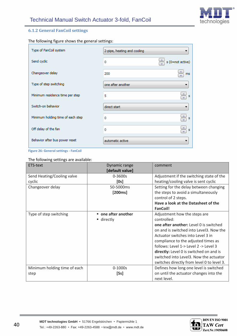
6.1.2 General FanCoil settings The following figure shows the general settings:
Figure 26: General settings - FanCoil
The following settings are available:
ETS-text Dynamic range [default value]
comment
Send Heating/Cooling valve cyclic
0-3600s [0s]
Adjustment if the switching state of the heating/cooling valve is sent cyclic
Changeover delay 50-5000ms [200ms]
Setting for the delay between changing the steps to avoid a simultaneously control of 2 steps. Have a look at the Datasheet of the FanCoil!
Type of step switching one after another directly
Adjustment how the steps are controlled: one after another: Level 0 is switched on and is switched into Level3. Now the Actuator switches into Level 3 in compliance to the adjusted times as follows: Level 1-> Level 2 -> Level 3 directly: Level 0 is switched on and is switched into Level3. Now the actuator switches directly from level 0 to level 3.
Minimum holding time of each step
0-1000s [5s]
Defines how long one level is switched on until the actuator changes into the next level.
Technical Manual Switch Actuator 3-fold, FanCoil
MDT technologies GmbH • 51766 Engelskirchen • Papiermühle 1
Tel.: +49-2263-880 • Fax: +49-2263-4588 • [email protected] • www.mdt.de 41
41
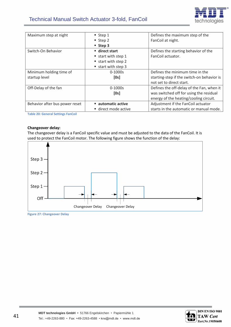
Maximum step at night Step 1 Step 2 Step 3
Defines the maximum step of the FanCoil at night.
Switch-On Behavior direct start start with step 1 start with step 2 start with step 3
Defines the starting behavior of the FanCoil actuator.
Minimum holding time of startup level
0-1000s [0s]
Defines the minimum time in the starting-step if the switch-on behavior is not set to direct start.
Off-Delay of the fan 0-1000s [0s]
Defines the off-delay of the Fan, when it was switched off for using the residual energy of the heating/cooling circuit.
Behavior after bus power reset automatic active direct mode active
Adjustment if the FanCoil actuator starts in the automatic or manual mode.
Table 20: General Settings FanCoil
Changeover delay: The changeover delay is a FanCoil specific value and must be adjusted to the data of the FanCoil. It is used to protect the FanCoil motor. The following figure shows the function of the delay:
Figure 27: Changeover Delay
Technical Manual Switch Actuator 3-fold, FanCoil
MDT technologies GmbH • 51766 Engelskirchen • Papiermühle 1
Tel.: +49-2263-880 • Fax: +49-2263-4588 • [email protected] • www.mdt.de 42
42
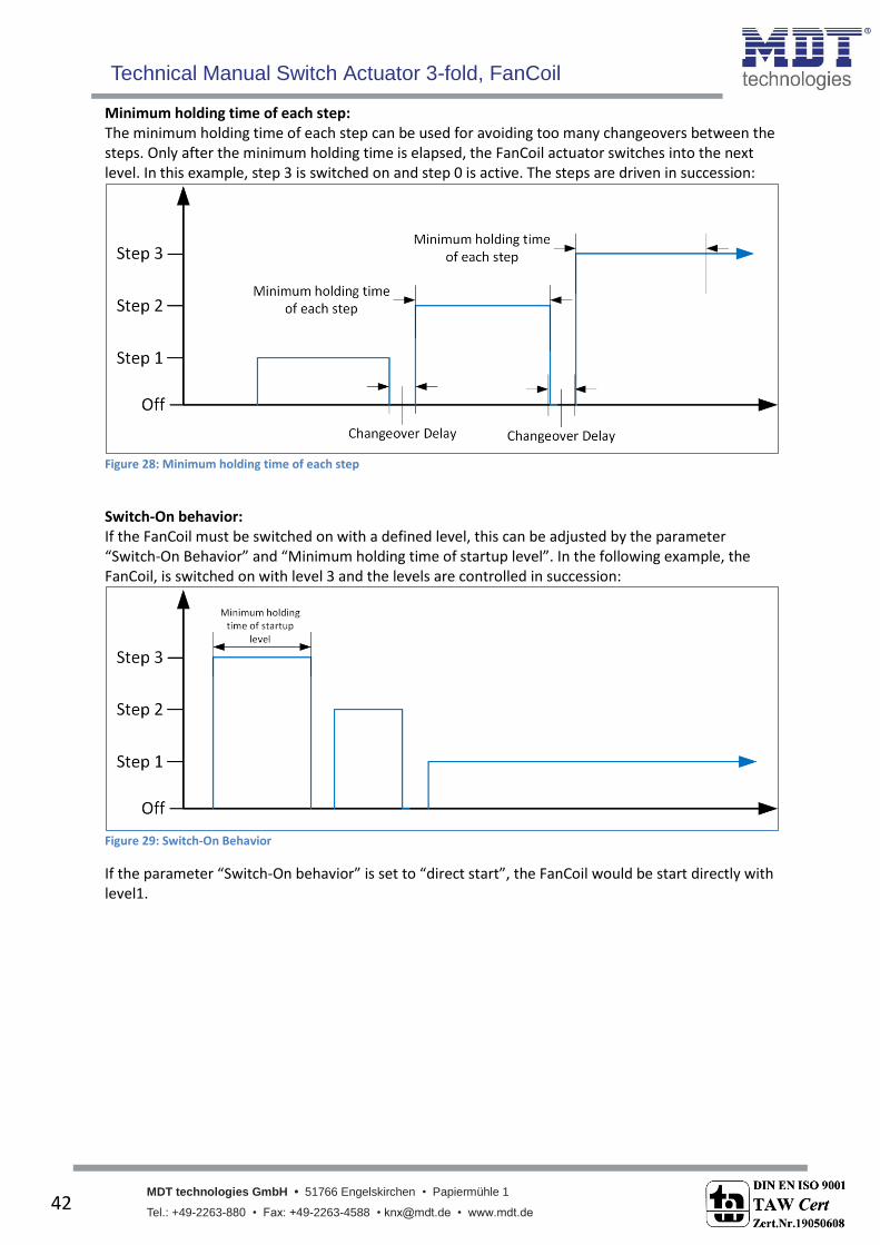
Minimum holding time of each step: The minimum holding time of each step can be used for avoiding too many changeovers between the steps. Only after the minimum holding time is elapsed, the FanCoil actuator switches into the next level. In this example, step 3 is switched on and step 0 is active. The steps are driven in succession:
Figure 28: Minimum holding time of each step
Switch-On behavior: If the FanCoil must be switched on with a defined level, this can be adjusted by the parameter “Switch-On Behavior” and “Minimum holding time of startup level”. In the following example, the FanCoil, is switched on with level 3 and the levels are controlled in succession:
Figure 29: Switch-On Behavior
If the parameter “Switch-On behavior” is set to “direct start”, the FanCoil would be start directly with level1.

Technical Manual Switch Actuator 3-fold, FanCoil
MDT technologies GmbH • 51766 Engelskirchen • Papiermühle 1
Tel.: +49-2263-880 • Fax: +49-2263-4588 • [email protected] • www.mdt.de 43
43
Off-Delay of the Fan: For using the residual energy off the heating/cooling circuit at switching the FanCoil off, the FanCoil can run after for a defined time. The valve is closed directly at the point off switching, but the FanCoil is switched after the Off-Delay is elapsed:
Figure 30: Off-Delay
The following table shows the available communication objects for these parameters:
Number Name Length Usage 6 Switch heating valve 1 Bit Switching the heating valve
6 Switch heating/cooling valve
1 Bit Switching the heating/cooling valve; at 2-Pipe heating/cooling systems
7 Switch cooling valve 1 Bit Switching the cooling valve Table 21: Communication objects - FanCoil general
6.1.3 Blocking Functions The following figure shows the available blocking functions:
Figure 31: Blocking Functions

Technical Manual Switch Actuator 3-fold, FanCoil
MDT technologies GmbH • 51766 Engelskirchen • Papiermühle 1
Tel.: +49-2263-880 • Fax: +49-2263-4588 • [email protected] • www.mdt.de 44
44
The following table shows the available settings:
ETS-text Dynamic range [default value]
comment
Block Object 1/2 not active active
Activates/Deactivates the blocking object
Action at Activation Blocking of 1/2
no reaction switch off valves and
ventilation switch to step 1 switch to step 2 switch to step 3
no reaction: The FanCoil is blocked for further control and stays in the current step. Switch off valves and ventilation: The FanCoil and the valve is switched off. Switch to step 1-3: The FanCoil is switched to the adjusted step.
Action at Deactivation Blocking of 1/2
no reaction switch to step 1 switch to step 2 switch to step 3 restore previous step
(Memory function)
no reaction: The FanCoil is blocked for further control and stays in the current step. Switch to step 1-3: The FanCoil is switched to the adjusted step. Memory function: The FanCoil restores the step which was active before blocking.
Table 22: Blocking function - FanCoil
The blocking objects 1 and 2 works independent of each other. Blocking object 1 has a higher priority than blocking object 2. The following table shows the available communication objects:
Number Name Length Usage 25 Block object 1 1 Bit Blocking the FanCoil
26 Block object 2 1 Bit Blocking the FanCoil Table 23: Communication objects - Blocking Function
6.1.4 Activation of further submenus For activating the menus of additional ventilation, automatic mode, direct mode and state functions, the following settings must be set to active:
Figure 32: Activation of the submenus
Technical Manual Switch Actuator 3-fold, FanCoil
MDT technologies GmbH • 51766 Engelskirchen • Papiermühle 1
Tel.: +49-2263-880 • Fax: +49-2263-4588 • [email protected] • www.mdt.de 45
45
6.2 Additional Ventilation
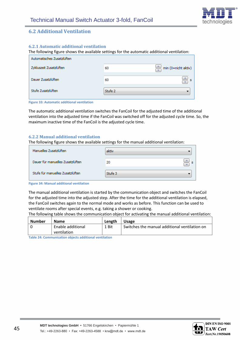
6.2.1 Automatic additional ventilation The following figure shows the available settings for the automatic additional ventilation:
Figure 33: Automatic additional ventilation
The automatic additional ventilation switches the FanCoil for the adjusted time of the additional ventilation into the adjusted time if the FanCoil was switched off for the adjusted cycle time. So, the maximum inactive time of the FanCoil is the adjusted cycle time.
6.2.2 Manual additional ventilation The following figure shows the available settings for the manual additional ventilation:
Figure 34: Manual additional ventilation
The manual additional ventilation is started by the communication object and switches the FanCoil for the adjusted time into the adjusted step. After the time for the additional ventilation is elapsed, the FanCoil switches again to the normal mode and works as before. This function can be used to ventilate rooms after special events, e.g. taking a shower or cooking. The following table shows the communication object for activating the manual additional ventilation:
Number Name Length Usage 0 Enable additional
ventilation 1 Bit Switches the manual additional ventilation on
Table 24: Communication objects additional ventilation

Technical Manual Switch Actuator 3-fold, FanCoil
MDT technologies GmbH • 51766 Engelskirchen • Papiermühle 1
Tel.: +49-2263-880 • Fax: +49-2263-4588 • [email protected] • www.mdt.de 46
46
6.3 Automatic Mode The automatic mode can be realized via control value or a Delta T control. The following communication object switches between automatic and direct mode:
Number Name Length Usage 1 Switching Auto/Manual 1 Bit Switchover between automatic and manual
mode Table 25: Communication object - Switchover Auto/Manual
The FanCoil actuator reacts only to control values or temperature values if the automatic mode is switched on. The selection of the steps in the direct mode is always possible. If a new step is selected via the direct mode, the FanCoil will be switched into the manual mode and the switchover object sends the state.
6.3.1 Automatic Mode – Control Value The following figure shows the available settings for the automatic mode via control values:
Figure 35: Automatic Mode - Control value
Technical Manual Switch Actuator 3-fold, FanCoil
MDT technologies GmbH • 51766 Engelskirchen • Papiermühle 1
Tel.: +49-2263-880 • Fax: +49-2263-4588 • [email protected] • www.mdt.de 47
47
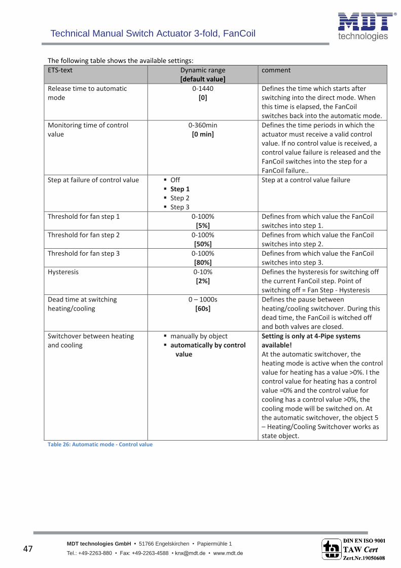
The following table shows the available settings:
ETS-text Dynamic range [default value]
comment
Release time to automatic mode
0-1440 [0]
Defines the time which starts after switching into the direct mode. When this time is elapsed, the FanCoil switches back into the automatic mode.
Monitoring time of control value
0-360min [0 min]
Defines the time periods in which the actuator must receive a valid control value. If no control value is received, a control value failure is released and the FanCoil switches into the step for a FanCoil failure..
Step at failure of control value Off Step 1 Step 2 Step 3
Step at a control value failure
Threshold for fan step 1
0-100% [5%]
Defines from which value the FanCoil switches into step 1.
Threshold for fan step 2
0-100% [50%]
Defines from which value the FanCoil switches into step 2.
Threshold for fan step 3
0-100% [80%]
Defines from which value the FanCoil switches into step 3.
Hysteresis 0-10% [2%]
Defines the hysteresis for switching off the current FanCoil step. Point of switching off = Fan Step - Hysteresis
Dead time at switching heating/cooling
0 – 1000s [60s]
Defines the pause between heating/cooling switchover. During this dead time, the FanCoil is witched off and both valves are closed.
Switchover between heating and cooling
manually by object automatically by control
value
Setting is only at 4-Pipe systems available! At the automatic switchover, the heating mode is active when the control value for heating has a value >0%. I the control value for heating has a control value =0% and the control value for cooling has a control value >0%, the cooling mode will be switched on. At the automatic switchover, the object 5 – Heating/Cooling Switchover works as state object.
Table 26: Automatic mode - Control value
Technical Manual Switch Actuator 3-fold, FanCoil
MDT technologies GmbH • 51766 Engelskirchen • Papiermühle 1
Tel.: +49-2263-880 • Fax: +49-2263-4588 • [email protected] • www.mdt.de 48
48
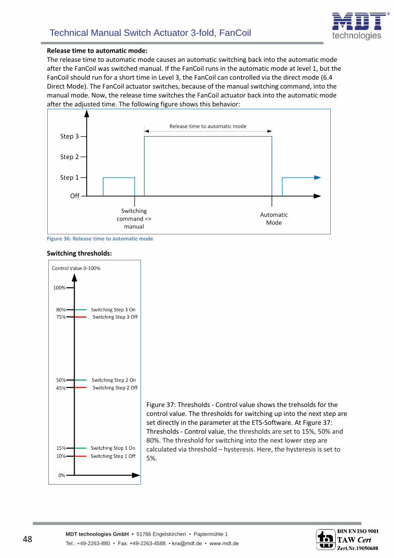
Release time to automatic mode: The release time to automatic mode causes an automatic switching back into the automatic mode after the FanCoil was switched manual. If the FanCoil runs in the automatic mode at level 1, but the FanCoil should run for a short time in Level 3, the FanCoil can controlled via the direct mode (6.4 Direct Mode). The FanCoil actuator switches, because of the manual switching command, into the manual mode. Now, the release time switches the FanCoil actuator back into the automatic mode after the adjusted time. The following figure shows this behavior:
Figure 36: Release time to automatic mode
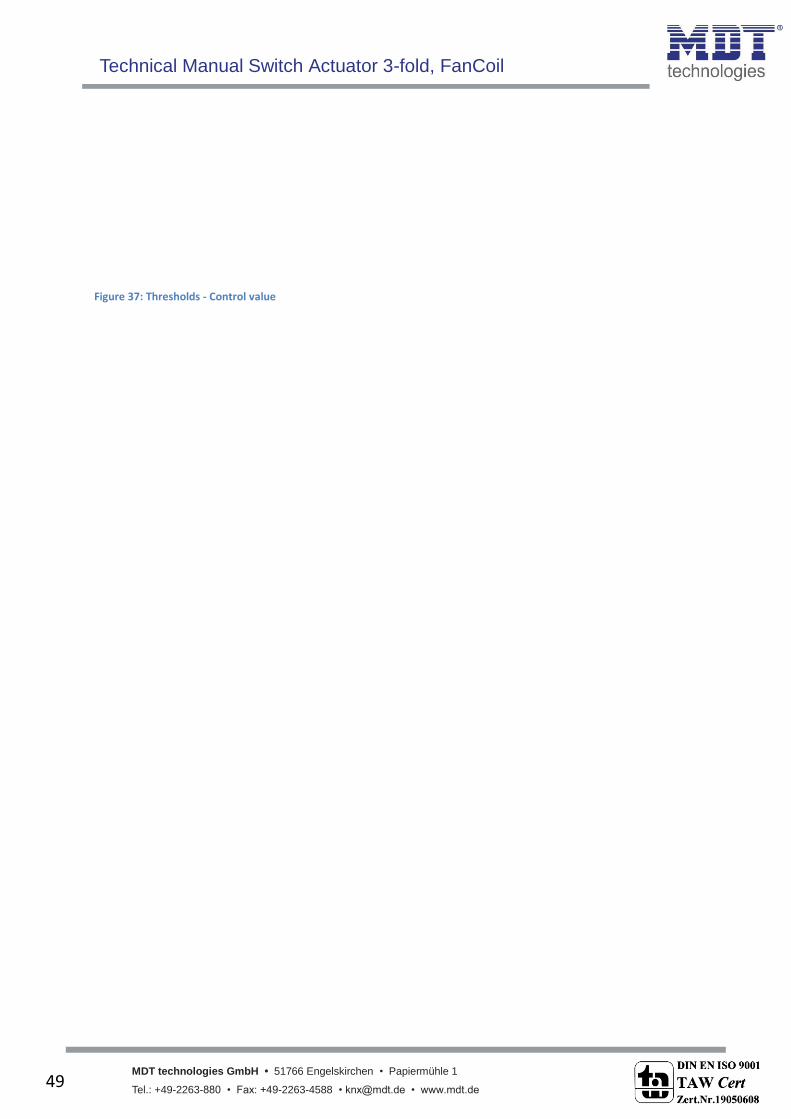
Switching thresholds: Figure 37: Thresholds - Control value shows the trehsolds for the control value. The thresholds for switching up into the next step are set directly in the parameter at the ETS-Software. At Figure 37: Thresholds - Control value, the thresholds are set to 15%, 50% and 80%. The threshold for switching into the next lower step are calculated via threshold – hysteresis. Here, the hysteresis is set to 5%.
Technical Manual Switch Actuator 3-fold, FanCoil
MDT technologies GmbH • 51766 Engelskirchen • Papiermühle 1
Tel.: +49-2263-880 • Fax: +49-2263-4588 • [email protected] • www.mdt.de 49
49
Figure 37: Thresholds - Control value

Technical Manual Switch Actuator 3-fold, FanCoil
MDT technologies GmbH • 51766 Engelskirchen • Papiermühle 1
Tel.: +49-2263-880 • Fax: +49-2263-4588 • [email protected] • www.mdt.de 50
50
Dead time at switching heating/cooling The dead time between heating and cooling causes a pause between the switchover of heating and cooling. This function avoids ventilating with hot air after the FanCoil was switched from heating to cooling. The following figure shows the dead time at switching from heating into cooling:
Figure 38: Dead time at heating/cooling switchover
The following table shows the communication objects for the automatic mode – control value:
Number Name Length Usage 2 Control value heating 1 Byte Receiving a control value for heating
2 Control value heating/cooling
1 Byte Receiving a control value for heating/cooling; at 2-Pipe systems
3 Control value cooling 1 Byte Receiving a control value for cooling
4 Control value failure 1 Bit Showing a control value failure
5 Heating/Cooling switchover
1 Bit Switchover between heating/cooling; Showing the current state
Table 27: Communication object - Automatic mode control value

Technical Manual Switch Actuator 3-fold, FanCoil
MDT technologies GmbH • 51766 Engelskirchen • Papiermühle 1
Tel.: +49-2263-880 • Fax: +49-2263-4588 • [email protected] • www.mdt.de 51
51
6.3.2 Automatic mode – Delta T The following figure shows the available settings for the automatic mode via Delta T:
Figure 39: Automatic mode - Delta T
The following table shows the available settings:
ETS-text Dynamic range [default value]
comment
Release time to automatic mode
0-1440 [0]
Defines the time which starts after switching into the direct mode. When this time is elapsed, the FanCoil switches back into the automatic mode.
Monitoring time of control value
0-360min [0 min]
Defines the time periods in which the actuator must receive a valid control value. If no control value is received, a control value failure is released and the FanCoil switches into the step for a FanCoil failure..

Technical Manual Switch Actuator 3-fold, FanCoil
MDT technologies GmbH • 51766 Engelskirchen • Papiermühle 1
Tel.: +49-2263-880 • Fax: +49-2263-4588 • [email protected] • www.mdt.de 52
52
Step at failure of control value Off Step 1 Step 2 Step 3
Step at a control value failure
Threshold for fan step 1
0-100% [5%]
Defines from which value the FanCoil switches into step 1.
Threshold for fan step 2
0-100% [50%]
Defines from which value the FanCoil switches into step 2.
Threshold for fan step 3
0-100% [80%]
Defines from which value the FanCoil switches into step 3.
Hysteresis 0-10% [2%]
Defines the hysteresis for switching off the current FanCoil step. Point of switching off = Fan Step - Hysteresis
Setpoint temperature 10°C – 30°C [21°C]
Adjustment of the setpoint
Setpoint offset by 2 Byte object not active active
Activation of the setpoint offset via 2 Byte.
Maximum setpoint offset 1,0k – 10,0K [1,0K]
Adjustment of the maximum setpoint offset
Setpoint offset by 1 Bit object not active active
The setpoint offset via 1 Bit object increases the setpoint at receiving a “1” by the adjusted step range and reduces the setpoint at receiving a “0” by the adjusted step range.
Step range 0,0K – 1,0K [0,5K]
Defines the step range fort eh setpoint offset via 1 Bit object.
Dead time at switching heating/cooling
0 – 1000s [60s]
Defines the pause between heating/cooling switchover. During this dead time, the FanCoil is witched off and both valves are closed.
Switchover between heating and cooling
manually by object by temperature and object
Adjustment is only at heating and cooling systems available! The automatic switchover switches automatically, in accordance to the received temperature and the current setpoint, between heating and cooling. At the automatic switchover, the object 5 – Heating/Cooling switchover, is used as state object.
Dead zone between heating and cooling
0,0K – 10,0K [2,0K]
The dead zone between heating and cooling is used for the automatic switchover between heating and cooling.
Table 28: Automatic mode - Delta T

Technical Manual Switch Actuator 3-fold, FanCoil
MDT technologies GmbH • 51766 Engelskirchen • Papiermühle 1
Tel.: +49-2263-880 • Fax: +49-2263-4588 • [email protected] • www.mdt.de 53
53
The settings „Release time to automatic mode“ and „Dead time at switching heating/cooling” are explained in chapter 6.3.1 Automatic Mode – Control Value. Thresholds:
Figure 40: Thresholds - Delta T
shows the thresholds for the temperature difference. The thresholds for switching up into the next step are set directly in the parameter at the ETS-Software. At Figure 40: Thresholds - Delta T the thresholds are set to 1K, 2K and 3,5K. The threshold for switching into the next lower step are calculated via threshold – hysteresis. Here, the hysteresis is set to 0,5K. The Delta T value is calculate with setpoint – temperature at the heating mode and with temperature – setpoint at the cooling mode.
Figure 40: Thresholds - Delta T
Switchover Heating/Cooling: At the automatic switchover via the temperature, a dead zone between heating and cooling can be defined to avoid too much switching. The dead zone is calculated symmetric around the setpoint. A dead zone of 2K at a setpoint of 21°C causes switching points at 20°C and 22°C:
Figure 41: Dead zone heating & cooling
Technical Manual Switch Actuator 3-fold, FanCoil
MDT technologies GmbH • 51766 Engelskirchen • Papiermühle 1
Tel.: +49-2263-880 • Fax: +49-2263-4588 • [email protected] • www.mdt.de 54
54
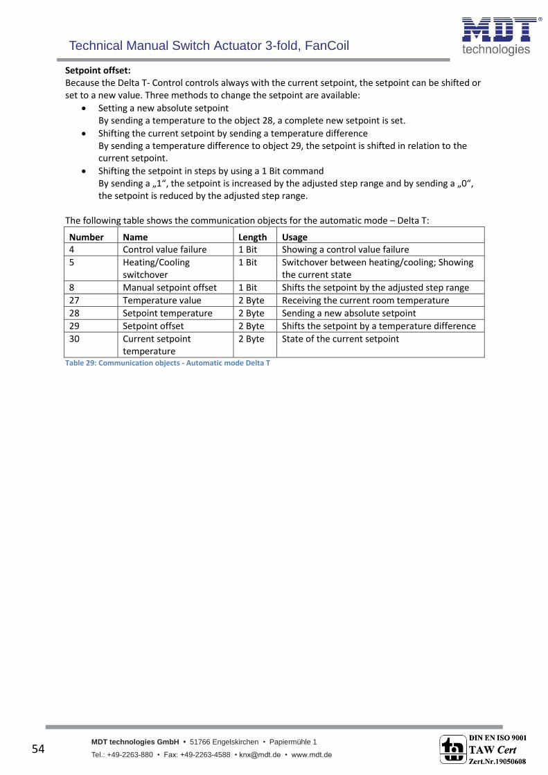
Setpoint offset: Because the Delta T- Control controls always with the current setpoint, the setpoint can be shifted or set to a new value. Three methods to change the setpoint are available:
Setting a new absolute setpoint By sending a temperature to the object 28, a complete new setpoint is set.
Shifting the current setpoint by sending a temperature difference By sending a temperature difference to object 29, the setpoint is shifted in relation to the current setpoint.
Shifting the setpoint in steps by using a 1 Bit command By sending a „1“, the setpoint is increased by the adjusted step range and by sending a „0“, the setpoint is reduced by the adjusted step range.
The following table shows the communication objects for the automatic mode – Delta T:
Number Name Length Usage 4 Control value failure 1 Bit Showing a control value failure
5 Heating/Cooling switchover
1 Bit Switchover between heating/cooling; Showing the current state
8 Manual setpoint offset 1 Bit Shifts the setpoint by the adjusted step range
27 Temperature value 2 Byte Receiving the current room temperature
28 Setpoint temperature 2 Byte Sending a new absolute setpoint
29 Setpoint offset 2 Byte Shifts the setpoint by a temperature difference
30 Current setpoint temperature
2 Byte State of the current setpoint
Table 29: Communication objects - Automatic mode Delta T
Technical Manual Switch Actuator 3-fold, FanCoil
MDT technologies GmbH • 51766 Engelskirchen • Papiermühle 1
Tel.: +49-2263-880 • Fax: +49-2263-4588 • [email protected] • www.mdt.de 55
55
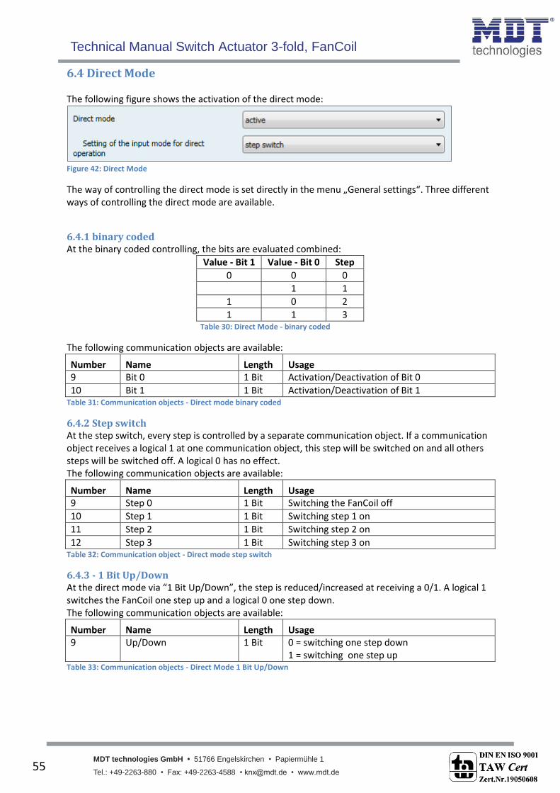
6.4 Direct Mode The following figure shows the activation of the direct mode:
Figure 42: Direct Mode
The way of controlling the direct mode is set directly in the menu „General settings“. Three different ways of controlling the direct mode are available.
6.4.1 binary coded At the binary coded controlling, the bits are evaluated combined:
Value - Bit 1 Value - Bit 0 Step
0 0 0
1 1
1 0 2
1 1 3 Table 30: Direct Mode - binary coded
The following communication objects are available:
Number Name Length Usage 9 Bit 0 1 Bit Activation/Deactivation of Bit 0
10 Bit 1 1 Bit Activation/Deactivation of Bit 1 Table 31: Communication objects - Direct mode binary coded
6.4.2 Step switch At the step switch, every step is controlled by a separate communication object. If a communication object receives a logical 1 at one communication object, this step will be switched on and all others steps will be switched off. A logical 0 has no effect. The following communication objects are available:
Number Name Length Usage 9 Step 0 1 Bit Switching the FanCoil off
10 Step 1 1 Bit Switching step 1 on
11 Step 2 1 Bit Switching step 2 on
12 Step 3 1 Bit Switching step 3 on Table 32: Communication object - Direct mode step switch
6.4.3 - 1 Bit Up/Down At the direct mode via “1 Bit Up/Down”, the step is reduced/increased at receiving a 0/1. A logical 1 switches the FanCoil one step up and a logical 0 one step down. The following communication objects are available:
Number Name Length Usage 9 Up/Down 1 Bit 0 = switching one step down
1 = switching one step up Table 33: Communication objects - Direct Mode 1 Bit Up/Down
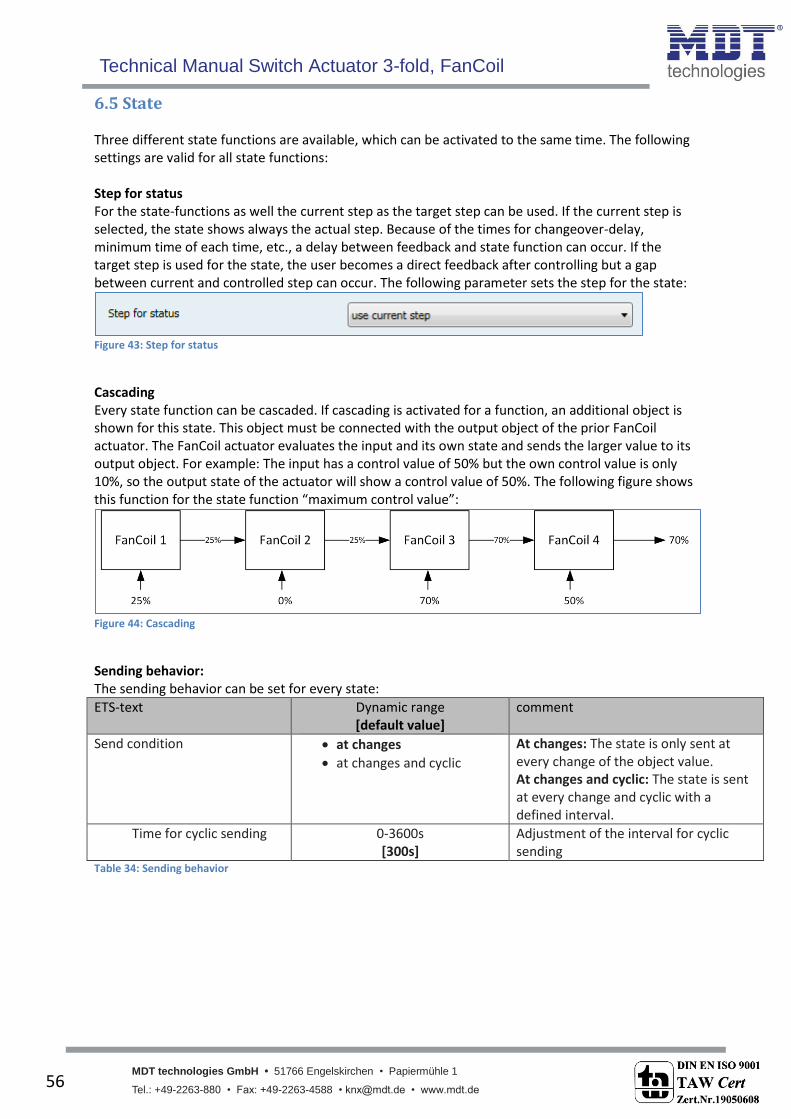
Technical Manual Switch Actuator 3-fold, FanCoil
MDT technologies GmbH • 51766 Engelskirchen • Papiermühle 1
Tel.: +49-2263-880 • Fax: +49-2263-4588 • [email protected] • www.mdt.de 56
56
6.5 State Three different state functions are available, which can be activated to the same time. The following settings are valid for all state functions: Step for status For the state-functions as well the current step as the target step can be used. If the current step is selected, the state shows always the actual step. Because of the times for changeover-delay, minimum time of each time, etc., a delay between feedback and state function can occur. If the target step is used for the state, the user becomes a direct feedback after controlling but a gap between current and controlled step can occur. The following parameter sets the step for the state:
Figure 43: Step for status
Cascading Every state function can be cascaded. If cascading is activated for a function, an additional object is shown for this state. This object must be connected with the output object of the prior FanCoil actuator. The FanCoil actuator evaluates the input and its own state and sends the larger value to its output object. For example: The input has a control value of 50% but the own control value is only 10%, so the output state of the actuator will show a control value of 50%. The following figure shows this function for the state function “maximum control value”:
Figure 44: Cascading
Sending behavior: The sending behavior can be set for every state:
ETS-text Dynamic range [default value]
comment
Send condition at changes
at changes and cyclic
At changes: The state is only sent at every change of the object value. At changes and cyclic: The state is sent at every change and cyclic with a defined interval.
Time for cyclic sending 0-3600s [300s]
Adjustment of the interval for cyclic sending
Table 34: Sending behavior

Technical Manual Switch Actuator 3-fold, FanCoil
MDT technologies GmbH • 51766 Engelskirchen • Papiermühle 1
Tel.: +49-2263-880 • Fax: +49-2263-4588 • [email protected] • www.mdt.de 57
57
6.5.1 Status Fan at heating/cooling mode active The state “Fan at heating/cooling mode” sends a “1” when the FanCoil is switched on – so runs at least with level 1. The cascading of the state has the effect that the output sends a “1” when the input has a “1” or the FanCoil is witched on. This state function can e.g. be used for switching a heating pump. The following objects are available:
Number Name Length Usage 13 External heating request
(Input) 1 Bit Input for cascading the heating request
14 External heating request (Output)
1 Bit Output of the heating request
15 External cooling request (Input)
1 Bit Input for cascading the cooling request
16 External cooling request (Output)
1 Bit Output of the cooling request
Table 35: Communication objects - State fan active
6.5.2 Status maximum control value The state maximum control value sends in the automatic mode-control value the received control value. The cascading of this state evaluates the input object and its own state and sends the larger value to its output object (Figure 44: Cascading). The following communication objects are available:
Number Name Length Usage 17 Maximum control value
for heating (Input) 1 Byte Input for cascading the state of the maximum
control value
18 Maximum control value for heating (Output)
1 Byte Output of the state of the maximum control value
19 Maximum control value for heating (Input)
1 Byte Input for cascading the state of the maximum control value
20 Maximum control value for heating (Output)
1 Byte Output of the state of the maximum control value
Table 36: Communication object - State maximum control value
6.5.3 Status maximum Level The state maximum level shows the current Fan Level. At cascading this state, the FanCoil actuator evaluates the input object and ist own Fan-Level and sends the bigger one to ist output object. The following communication objects are available:
Number Name Length Usage 21 Maximum fan level
heating (Input) 1 Bit Input for cascading the maximum Fan Level in
heating mode
22 Maximum fan level heating (Output)
1 Bit Output of the maximum Fan Level in heating mode
23 Maximum fan level cooling (Input)
1 Bit Input for cascading the maximum Fan Level in cooling mode
24 Maximum fan level cooling (Output)
1 Bit Output of the maximum Fan Level in cooling mode
Table 37: Communication objects - State maximum level

Technical Manual Switch Actuator 3-fold, FanCoil
MDT technologies GmbH • 51766 Engelskirchen • Papiermühle 1
Tel.: +49-2263-880 • Fax: +49-2263-4588 • [email protected] • www.mdt.de 58
58
7 Index
7.1 List of figures Figure 1: Exemplary circuit diagram - Actuator ....................................................................................... 4 Figure 2: Exemplary circuit diagram – FanCoil ........................................................................................ 5 Figure 3: Overview hardware .................................................................................................................. 6 Figure 4: Selection of the operating mode ............................................................................................ 18 Figure 5: Channel Selection ................................................................................................................... 19 Figure 6: Operating mode ..................................................................................................................... 20 Figure 7: Central function ...................................................................................................................... 21 Figure 8: Blocking function .................................................................................................................... 21 Figure 9: Switching output .................................................................................................................... 23 Figure 10: On/Off delay ......................................................................................................................... 25 Figure 11: Logical functions ................................................................................................................... 26 Figure 12: Overview Logic function ....................................................................................................... 26 Figure 13: Scene function ...................................................................................................................... 28 Figure 14: Sub function scene ............................................................................................................... 29 Figure 15: Programming of scenes ........................................................................................................ 32 Figure 16: Staircase ............................................................................................................................... 33 Figure 17: Staircase time ....................................................................................................................... 35 Figure 18: Warning timer & prewarning time ....................................................................................... 36 Figure 19: Manual switch off ................................................................................................................. 37 Figure 20: Extend staircase time ........................................................................................................... 37 Figure 21: Selection of the FanCoil system ........................................................................................... 38 Figure 22: 2-Pipe system - Heating ........................................................................................................ 38 Figure 23: 2-Pipe System - Cooling ........................................................................................................ 38 Figure 24: 2-Pipe System - Heating and Cooling ................................................................................... 39 Figure 25: 4-Pipe System - Heating & Cooling ....................................................................................... 39 Figure 26: General settings - FanCoil ..................................................................................................... 40 Figure 27: Changeover Delay ................................................................................................................. 41 Figure 28: Minimum holding time of each step .................................................................................... 42 Figure 29: Switch-On Behavior .............................................................................................................. 42 Figure 30: Off-Delay............................................................................................................................... 43 Figure 31: Blocking Functions ................................................................................................................ 43 Figure 32: Activation of the submenus ................................................................................................. 44 Figure 33: Automatic additional ventilation.......................................................................................... 45 Figure 34: Manual additional ventilation .............................................................................................. 45 Figure 35: Automatic Mode - Control value .......................................................................................... 46 Figure 36: Release time to automatic mode ......................................................................................... 48 Figure 37: Thresholds - Control value ................................................................................................... 48 Figure 38: Dead time at heating/cooling switchover ............................................................................ 49 Figure 39: Automatic mode - Delta T .................................................................................................... 50 Figure 40: Thresholds - Delta T .............................................................................................................. 52 Figure 41: Dead zone heating & cooling ............................................................................................... 52 Figure 42: Direct Mode .......................................................................................................................... 54 Figure 43: Step for status ...................................................................................................................... 55 Figure 44: Cascading .............................................................................................................................. 55
Technical Manual Switch Actuator 3-fold, FanCoil
MDT technologies GmbH • 51766 Engelskirchen • Papiermühle 1
Tel.: +49-2263-880 • Fax: +49-2263-4588 • [email protected] • www.mdt.de 59
59
7.2 List of tables Table 1: Overview communication objects - Switch actuator ................................................................. 9 Table 2: Communication objects - Default settings - Switch actuator .................................................. 10 Table 3: Overview communication objects - FanCoil ............................................................................ 15 Table 4: Communication objects - Default settings – FanCoil ............................................................... 17 Table 5: General settings ....................................................................................................................... 18 Table 6: Communication objects - General ........................................................................................... 18 Table 7: Operating mode ....................................................................................................................... 20 Table 8: Central function ....................................................................................................................... 21 Table 9: Communication object central function .................................................................................. 21 Table 10: Behavior at block/unblock ..................................................................................................... 21 Table 11: Communication object blocking function.............................................................................. 22 Table 12: Switching output .................................................................................................................... 24 Table 13: Communication objects logic ................................................................................................ 26 Table 14: Logic function ........................................................................................................................ 27 Table 15: Communication object scene ................................................................................................ 28 Table 16: Parameter scene .................................................................................................................... 30 Table 17: Calling and saving scenes....................................................................................................... 31 Table 18: Parameter staircase ............................................................................................................... 34 Table 19: Communication object staircase ........................................................................................... 35 Table 20: General Settings FanCoil ........................................................................................................ 41 Table 21: Communication objects - FanCoil general ............................................................................. 43 Table 22: Blocking function - FanCoil .................................................................................................... 44 Table 23: Communication objects - Blocking Function ......................................................................... 44 Table 24: Communication objects additional ventilation ..................................................................... 45 Table 25: Communication object - Switchover Auto/Manual ............................................................... 46 Table 26: Automatic mode - Control value ........................................................................................... 47 Table 27: Communication object - Automatic mode control value ...................................................... 49 Table 28: Automatic mode - Delta T...................................................................................................... 51 Table 29: Communication objects - Automatic mode Delat T .............................................................. 53 Table 30: Direct Mode - binary coded ................................................................................................... 54 Table 31: Communication objects - Direct mode binary coded ............................................................ 54 Table 32: Communication object - Direct mode step switch ................................................................ 54 Table 33: Communication objects - Direct Mode 1 Bit Up/Down ......................................................... 54 Table 34: Sending behavior ................................................................................................................... 55 Table 35: Communication objects - State fan active ............................................................................. 56 Table 36: Communication object - State maximum control value ........................................................ 56 Table 37: Communication objects - State maximum level .................................................................... 56
Technical Manual Switch Actuator 3-fold, FanCoil
MDT technologies GmbH • 51766 Engelskirchen • Papiermühle 1
Tel.: +49-2263-880 • Fax: +49-2263-4588 • [email protected] • www.mdt.de 60
60
8 Attachment
8.1 Statutory requirements
The above-described devices must not be used with devices, which serve directly or indirectly the
purpose of human, health- or lifesaving. Further the devices must not be used if their usage can
occur danger for humans, animals or material assets.
Do not let the packaging lying around careless, plastic foil/ -bags etc. can be a dangerous toy for kids.
8.2 Routine disposal
Do not throw the waste equipment in the household rubbish. The device contains electrical devices,
which must be disposed as electronic scrap. The casing contains of recyclable synthetic material.
8.3 Assemblage
Risk for life of electrical power!
All activities on the device should only be done by an electrical specialist. The county specific
regulations and the applicable EIB-directives have to be observed.
8.4 Datasheet