06/2016 technical manual mdt ip interface
TRANSCRIPT

MDT technologies GmbH • 51766 Engelskirchen • Papiermühle 1
Tel.: +49-2263-880 • Fax: +49-2263-4588 • [email protected] • www.mdt.de
06/2016
Technical Manual
MDT IP Interface
SCN-IP000.02

Technical Manual IP Interface – SCN-IP000.02
MDT technologies GmbH • 51766 Engelskirchen • Papiermühle 1
Tel.: +49-2263-880 • Fax: +49-2263-4588 • [email protected] • www.mdt.de 2
1 Contents
1 Contents ............................................................................................................................................... 2
2 Overview ............................................................................................................................................... 4
2.1 Areas of application IP-Interface ................................................................................................... 4
2.2 Areas of application E-Mail Client ................................................................................................. 4
2.3 Areas of application Timeserver .................................................................................................... 4
2.4 Overview LEDS & Operation .......................................................................................................... 5
2.5 Commissioning .............................................................................................................................. 6
3 Parameter –> IP-Interface .................................................................................................................... 7
3.1 General .......................................................................................................................................... 7
3.2 IP –Configuration ........................................................................................................................... 8
3.2.1 Example of assigning IP addresses ......................................................................................... 9
3.3 Communication settings .............................................................................................................. 10
3.3.1 Procedure ETS 4 .................................................................................................................... 10
3.3.2 Procedure ETS 5 .................................................................................................................... 11
3.3.3 More than one connection ................................................................................................... 13
4 Parameter –> E-Mail Client ................................................................................................................ 14
4.1 General settings ........................................................................................................................... 14
4.1.1 General ................................................................................................................................. 14
4.1.2 Web-Interface ...................................................................................................................... 15
4.1.3 Time/Date ............................................................................................................................. 16
4.2 E-Mail functions ........................................................................................................................... 17
4.2.1 Status elements .................................................................................................................... 17
4.2.2 Bit alarms .............................................................................................................................. 19
Macros ....................................................................................................................................... 20
4.2.3 Text alarms ........................................................................................................................... 21
4.2.4 Status reports ....................................................................................................................... 22
4.2.5 Specific behavior and error handling ................................................................................... 23
4.3 Overview communication objects ............................................................................................... 24
5 Web-Interface..................................................................................................................................... 26
5.1 Call of the Web-Interface ............................................................................................................ 26
5.2 Overview Web-Interface ............................................................................................................. 27
5.3 Setting of E-Mail functionality ..................................................................................................... 28
5.4 E-Mail – Error codes & remedy ................................................................................................... 31
5.5 Receive E-Mail as push message ................................................................................................. 31
5.6 Receive E-Mail as SMS ................................................................................................................. 31

Technical Manual IP Interface – SCN-IP000.02
MDT technologies GmbH • 51766 Engelskirchen • Papiermühle 1
Tel.: +49-2263-880 • Fax: +49-2263-4588 • [email protected] • www.mdt.de 3
6 Index ................................................................................................................................................... 32
6.1 Register of illustrations ................................................................................................................ 32
6.2 List of tables................................................................................................................................. 33
7 Attachment ......................................................................................................................................... 34
7.1 Statutory requirements ............................................................................................................... 34
7.2 Routine disposal .......................................................................................................................... 34
7.3 Assemblage .................................................................................................................................. 34
7.4 Datasheet .................................................................................................................................... 34

Technical Manual IP Interface – SCN-IP000.02
MDT technologies GmbH • 51766 Engelskirchen • Papiermühle 1
Tel.: +49-2263-880 • Fax: +49-2263-4588 • [email protected] • www.mdt.de 4
2 Overview
The MDT IP Interface, SCN IP000.02, has 2 parallel applications.
On the one hand there is one application for the IP Interface (Step 1), which allows access to the bus
via Ethernet.
The second application (Step 2) is on the TP side and can send by KNX triggered emails, serve as a
time server and provides access to the device via a Web-Interface.
Table 1: Database for applications
Important: As these are 2 different applications, both applications must be programmed
independently. The IP interface must get 2 physical addresses!
Specifics:
Use as a time server
Extensive email functionality with status information from the KNX bus
Supplied completely from the KNX bus, no additional power supply required!
2.1 Areas of application IP-Interface
The MDT IP interface connects the KNX bus with an Ethernet network. Through the network, KNX
telegrams can be sent to other devices or received from. For communication, the device uses the
KNXnet / IP protocol of the KNX Association. It thus operates as a programming interface and
replaces a RS232 or USB interface.
The IP interface includes a tunneling function for point-to-point connection.
The power is supplied via the KNX bus.
2.2 Areas of application E-Mail Client
The email client can emit status reports, bit alarms and text alarms. All email events can be triggered
via KNX telegrams. In addition, status reports can also be sent at fixed times - the email client has the
functionality to work as a clock-master. All e-mails can be sent to up to 3 addresses simultaneously.
The settings of the e-mail functionality can be carried out comfortably via the web interface.
2.3 Areas of application Timeserver
The IP Interface receives the date and time of the NTP server and can distribute them as the
"master" to further KNX devices via the bus.

Technical Manual IP Interface – SCN-IP000.02
MDT technologies GmbH • 51766 Engelskirchen • Papiermühle 1
Tel.: +49-2263-880 • Fax: +49-2263-4588 • [email protected] • www.mdt.de 5
2.4 Overview LEDS & Operation
The figure below shows the structure of the device and the location of the LEDs:
Figure 1: Structure Hardware module
1. LED Bus State - LAN
2. LED Bus State - KNX
3. LED Traffic - LAN
4. LED Traffic - KNX
5. no function
6. no function
7. Function button
8. Programming LED
9. Programming button
Function of Programming-button:
Short press: programming LED lights steady red -> IP interface is in the programming mode
Long press: programming LED flashes red -> E-Mail client is in the programming mode
Reset device:
Press the Function button (7) for 15sec, the LEDs 1,2,5 and 6 light red. Now release the Function
button and press it again until all LEDs turn off. The device will reboot.
Now the device is reset to factory settings.
1 2
3 4
5 6
7
9 8

Technical Manual IP Interface – SCN-IP000.02
MDT technologies GmbH • 51766 Engelskirchen • Papiermühle 1
Tel.: +49-2263-880 • Fax: +49-2263-4588 • [email protected] • www.mdt.de 6
Green Red
LED 1
Bus State - LAN
Off: LAN Error
On: LAN OK
LED 2
Bus State - KNX
Off: KNX Bus: Error or not connected
On: KNX Bus OK
LED 3
Traffic - LAN
Flashing: Bus load at LAN-side
Off: No Bus load at LAN-side
Speed up to 10 Mbit/s
Flashing: Transmission error at LAN
side
LED 4
Traffic - KNX
Flashing: Bus load at KNX side
Off: No Bus load at KNX side
Flashing: Transmission error at KNX
side Table 2: Overview LEDs
2.5 Commissioning
The following procedure is recommended for commissioning the SCN-IP000.02:
1. Configuration of the IP-Interface:
2. Transfer of the physical address and the application of the IP Interface. For this, the
programming button must be pressed shortly. The programming LED lights steady red.
3. After successful transfer of the physical address and the application, the red LED turns off
again.
4. Configuration of the E-Mail Client:
5. Transfer of the physical address and the application of the E-Mail Client. For this, the
programming button must be pressed long. The programming LED flashes red.
6. After successful transfer of the physical address and the application, the red LED turns off
again.
7. Accessing the Web client to configure the e-mail addresses by opening an Internet browser
and call the address: http:\\IP address: port, for example: http: \\192.168.1.178:8080 for the
IP address 192.168 .1.178 and the http port 8080
Important: If the IP address of the IP interfaces gets changed subsequently, the device must perform
a reboot. This restart is not performed automatically by the application programming in the ETS4/5.
Here, a manual restart will be required, which either by right-clicking on the device and selecting
"Reset device" is executed or a short removing of the bus connector.
Technical Manual IP Interface – SCN-IP000.02
MDT technologies GmbH • 51766 Engelskirchen • Papiermühle 1
Tel.: +49-2263-880 • Fax: +49-2263-4588 • [email protected] • www.mdt.de 7
3 Parameter –> IP-Interface
3.1 General
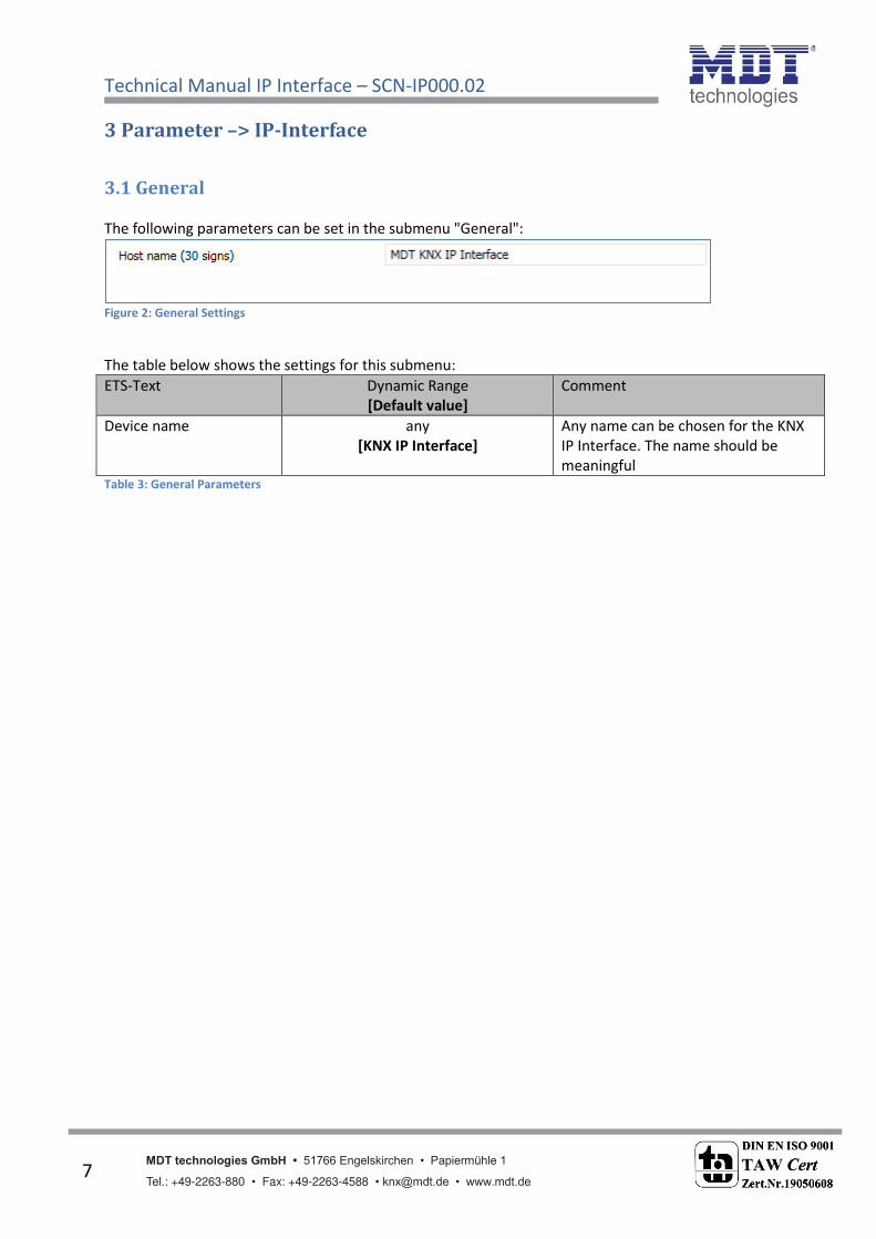
The following parameters can be set in the submenu "General":
Figure 2: General Settings
The table below shows the settings for this submenu:
ETS-Text Dynamic Range
[Default value]
Comment
Device name any
[KNX IP Interface]
Any name can be chosen for the KNX
IP Interface. The name should be
meaningful Table 3: General Parameters

Technical Manual IP Interface – SCN-IP000.02
MDT technologies GmbH • 51766 Engelskirchen • Papiermühle 1
Tel.: +49-2263-880 • Fax: +49-2263-4588 • [email protected] • www.mdt.de 8
3.2 IP –Configuration
The following parameters can be set in the submenu "IP Configuration":
Figure 3: IP Configuration 1
The following table shows the setting options for this submenu:
ETS-Text Dynamic Range
[Default value]
Comment
HTTP Port 80
8080
Specifying of the http port
DHCP use
not in use
Setting whether the IP address should be
assigned automatically via DHCP or manually
be set in further submenus
IP-address (0-255).(0-255).(0-255).(0-255)
0.0.0.0
IP-address of the router
only with manual IP address
assignment
Net mask (0-255).(0-255).(0-255).(0-255)
0.0.0.0
Subnet mask of the network
only with manual IP address
assignment
Gateway (0-255).(0-255).(0-255).(0-255)
0.0.0.0
Gateway-address of the network
only with manual IP address
assignment
DNS (0-255).(0-255).(0-255).(0-255)
0.0.0.0
Domain Name Server of the network
only with manual IP address
assignment Table 4: IP Configuration

Technical Manual IP Interface – SCN-IP000.02
MDT technologies GmbH • 51766 Engelskirchen • Papiermühle 1
Tel.: +49-2263-880 • Fax: +49-2263-4588 • [email protected] • www.mdt.de 9
The assignment of the IP address of the device can be done either manually or by a DHCP server, this
is often available in DSL routers.
When selecting DHCP - do not use , the IP configuration can be set manually.
When selecting "DHCP – use , a DHCP server must assign a valid IP address to the KNX / IP router. If
there is no DHCP server available, the router restarts after a certain waiting period with an AutoIP
address (address range of 169.254.1.0 to 169.254.254.255). Once a DHCP server is available, it
automatically assignes a new IP address to the device.
IP-address
The IP address must be allocated so that the bytes 1-3 are the same as those of the communicating
computers. So the membership is given on the network. The 4th byte must be any available IP
address (0-255) on the network, so as to avoid addressing conflicts.
The subnet mask is used for the device to determine whether a communication partner is located in
the local network. Should not be a partner in the local network, the device does not send the
telegrams directly to the partner but to the gateway, which handles the routing.
The setting of the gateway makes it possible for networks, which are based on different protocols to
communicate with each other.
Note: If the KNX IP Interface is only be used in the local LAN, the entry can remain 0.0.0.0.
The network settings of the communicating computers can be read in the network settings of the PC.
3.2.1 Example of assigning IP addresses
A KNX IP interface to be accessed via PC. The PC has the following IP settings:
IP address of the PC: 192.168.1.30
Subnet of the PC: 255.255.255.0
Is the KNX IP Interface located in the same local LAN, i.e. it uses the same subnet, the assignment of
the IP address is restricted by the subnet. That means in this example the IP address of the IP router
has to be 192.168.1.xx. xx can be a number from 1 to 254 (with the exception of 30, which has
already been used). It must be ensured, no numbers are assigned twice. The following settings can
therefore be made in the IP Interface:
IP address of the IP Interface: 192.168.1.31
Subnet of the IP Interface: 255.255.255.0
Technical Manual IP Interface – SCN-IP000.02
MDT technologies GmbH • 51766 Engelskirchen • Papiermühle 1
Tel.: +49-2263-880 • Fax: +49-2263-4588 • [email protected] • www.mdt.de 10
3.3 Communication settings
If the IP configuration of the KNX Interface is valid, the device can be used as an interface to KNX/EIB.
Therefore, connect the IP Interface to the KNX bus and the network.
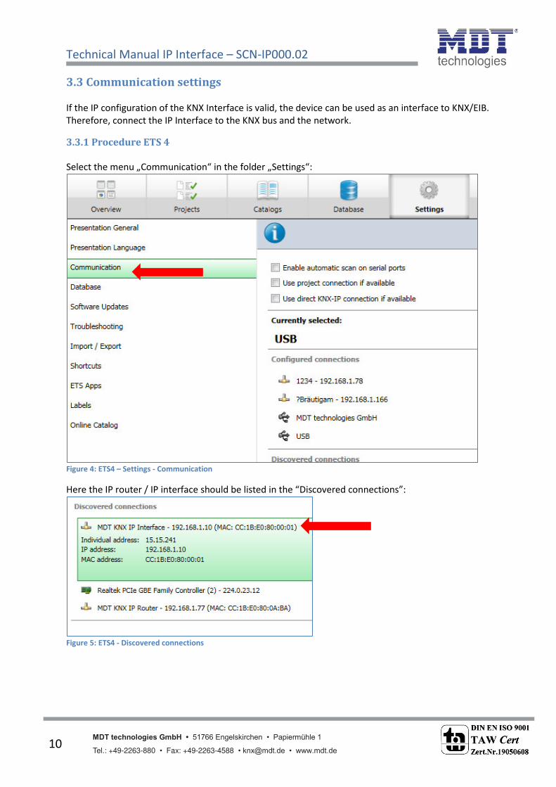
3.3.1 Procedure ETS 4
“ele t the e u „Communication i the folder „“etti gs :
Figure 4: ETS4 – Settings - Communication
Here the IP router / IP interface should be listed in the Discovered connections :
Figure 5: ETS4 - Discovered connections

Technical Manual IP Interface – SCN-IP000.02
MDT technologies GmbH • 51766 Engelskirchen • Papiermühle 1
Tel.: +49-2263-880 • Fax: +49-2263-4588 • [email protected] • www.mdt.de 11
The connection can be choosen as active by clicking on "Select". Now the settings for this interface
can be configured by selecting the button "Settings":
Figure 6: ETS4 - Local Settings Interface
Here, the first tunneling address can be assigned.
3.3.2 Procedure ETS 5
“ele t „I terfa es i e u „Bus :
Figure 7: ETS5 - Bus - Interfaces

Technical Manual IP Interface – SCN-IP000.02
MDT technologies GmbH • 51766 Engelskirchen • Papiermühle 1
Tel.: +49-2263-880 • Fax: +49-2263-4588 • [email protected] • www.mdt.de 12
Here the IP router / IP interface should be listed in the Discovered connections :
Figure 8: ETS5 - Discovered connections
After sele ti g the IP Router/IP I terfa e press utto Test . If OK ou a press utto “ele t .
Figure 9: ETS5 - Interface Test/Select
No de i e is sho as Curre t I terfa e
For the selected IP router / IP interface, the first tunneling connection can then be set:
Figure 10: ETS5 - IP Tunneling connection

Technical Manual IP Interface – SCN-IP000.02
MDT technologies GmbH • 51766 Engelskirchen • Papiermühle 1
Tel.: +49-2263-880 • Fax: +49-2263-4588 • [email protected] • www.mdt.de 13
3.3.3 More than one connection
The KNX IP router / KNX IP interface supports up to 4 simultaneous connections. The first physical
address is adjusted as described under 3.3 in the ETS connections. In the Web-Interface, the further
physical addresses can be assigned automatically pressi g the “et utto i the e u
Prog.Mode :
Figure 11: Set Tunneling Addresses in "Prog.Mode"
Now the 3 following physical addresses are assigned. If, for example, the IP Interface has got the first
tunneling address assigned to the physical address 15.15.241, so the device provides further
tunneling addresses automatically to 15.15.242, 15.15.243 and 15.15.244. When the first address
was assigned to x.x.255, so the further tunneling addresses are not assigned automatically!

Technical Manual IP Interface – SCN-IP000.02
MDT technologies GmbH • 51766 Engelskirchen • Papiermühle 1
Tel.: +49-2263-880 • Fax: +49-2263-4588 • [email protected] • www.mdt.de 14
4 Parameter –> E-Mail Client
4.1 General settings
4.1.1 General
The following figure shows the general settings:
Figure 12: General settings E-Mail Client
Startup delay time
The Startup delay time determines the time between a bus voltage recovery and a functional device
start.
Telegram Operation
With the cyclic In operation telegram , a failure detection for this device can be realized.
Language for email content
Here is selected in which language the email contents are sent.
Device name
The device name is displayed in the e-mail and can be integrated via macros in the email. It is
advisable here to assign a meaningful name of the object, in which the IP interface is used.

Technical Manual IP Interface – SCN-IP000.02
MDT technologies GmbH • 51766 Engelskirchen • Papiermühle 1
Tel.: +49-2263-880 • Fax: +49-2263-4588 • [email protected] • www.mdt.de 15
4.1.2 Web-Interface
The following settings are available to set-up the web interface:
Table 5: Settings Web-Interface
Password
The password is used to control access to the Web Interface. There should always be a password be
entered!
Timeout for valid login
The parameter specifies the time at which the web interface can be reached after a login. After the
set time, the web interface is automatically locked.
Timeout startup of the web interface after reset
The parameter specifies the time how long the web interface can be reached after restarting
(switching ON the bus voltage or reset via ETS). After the set time, the Web interface is no more
accessible and can only be reached after a restart or after an activation of the web interface via
object.
Temporary activation of the web interface for Email event
The parameter allows the temporal activation of the web interface after sending an email.
Activation/deactivation of the web interface over object
To activate via bus, regardless of any other settings, a communication object can be displayed to
activate the web interface via object.
Following communication object appears for this purpose:
Number Name Lenght Usage
55 Web interface 1 Bit lock/unlock of Web-Interface Table 6: Communication object - lock/unlock Web-Interface
Attention: For security reasons it is recommended to disable the web interface after a certain time
using the parameter "Timeout startup of the web interface after reset" or to activate the web
interface only via object and deactivate when not in use!

Technical Manual IP Interface – SCN-IP000.02
MDT technologies GmbH • 51766 Engelskirchen • Papiermühle 1
Tel.: +49-2263-880 • Fax: +49-2263-4588 • [email protected] • www.mdt.de 16
4.1.3 Time/Date
The following settings are available for time and date:
Table 7: Settings Time/Date
Send cyclic system time each…
Setting whether the system time is to be sent cyclically.
Summer/Winter time change
Setting whether the time is switched automatically between summer and winter time.
Time difference to universal time UTC+…
Setting of timezone.
The following communication objects are displayed:
Number Name Lenght Usage
2 Time 3 Byte Sending Time
3 Date 3 Byte Sending Date
4 Date/Time 8 Byte Sending Date and Time Table 8: Communication objects - Time/Date

Technical Manual IP Interface – SCN-IP000.02
MDT technologies GmbH • 51766 Engelskirchen • Papiermühle 1
Tel.: +49-2263-880 • Fax: +49-2263-4588 • [email protected] • www.mdt.de 17
4.2 E-Mail functions
The IP interface supports extensive email functionality. Thus, up to 30 status items are available,
whose names and values can be displayed in the emails. The emails can be triggered via bit telegrams
(bit alarms) or by sending text strings (Text alarms).
Furthermore can be sent up to 3 status reports, in which the 30 status items can be displayed. These
status reports can be sent out by objects as well as at fixed times.
The configuration of the e-mail functionality, such as sending e-mail address, e-mail recipients, etc.,
is ade i the e i terfa e, see 5 We i terfa e .
4.2.1 Status elements
For the Status element 1 following settings is available:
Table 9: Settings - Status element 1
Each state element, a display name and a data point type can be assigned. The display name can then
be reported in the emails.
The following data point types with the corresponding values can be set:
Lenght: 1 Bit
Data point type Value for 1 Value for 0
1 Bit Switch On Off
1 Bit Lock Locked Unlocked
1 Bit Up/Down Down Up
1 Bit Open/Closed Closed Open
1 Bit Heating/Cooling Heating Cooling
1 Bit Yes/No Yes No
1 Bit Present/Absent Present Absent
1 Bit Day Day Night
1 Bit Night Night Day Table 10: Status elements - 1 Bit

Technical Manual IP Interface – SCN-IP000.02
MDT technologies GmbH • 51766 Engelskirchen • Papiermühle 1
Tel.: +49-2263-880 • Fax: +49-2263-4588 • [email protected] • www.mdt.de 18
Lenght 1 Byte
Data point type Dynamic range
1 Byte value 0-255
1 Byte Percent value 0-100%
1 Byte HVAC Status 0x01 -> Comfort
0x02 -> Standby
0x03 -> Night
0x04 -> Frost-/Heat protection
1 Byte HVAC Mode The HVAC mode is evaluated bit by bit
and displayed:
Bit 0 -> 1 = Comfort
Bit 1 -> 1 = Standby
Bit 2 -> 1 = Night
Bit 3 -> 1 = Frost-/Heat protection
Bit 5 -> 0 = Cooling/ 1= Heating
Bit 7 -> 1 = Frost alarm Figure 13: Status elements - 1 byte
Lenght 2 Byte
Data point type Dynamic range
2 Byte unsigned value 0 – 65535
2 Byte signed value -32768 – 32767
2 Byte floating value -670760 – 670760 Table 11: Status elements - 2 byte
Lenght 4 Byte
Data point type Dynamic range
4 Byte unsigned value 0 – 4 294 967 295
4 Byte signed value -2 147 483 648 – 2 147 483 647
4 Byte floating value Floating point according to IEEE 754 Table 12: Status elements - 4 byte
Lenght 14 Byte Zeichen
Data point type Dynamic range
14 Byte String (ISO 8859-1) Any string with max. 14 characters Table 13: Status elements - 14 byte
The following table shows the available communication objects:
Number Name Length Usage
21 Status element 1 1 Bit
1 Byte
2 Byte
4 Byte
14 Byte
Setting the value of the status element
+1 next status element Table 14: Communication objects - Status elements
Technical Manual IP Interface – SCN-IP000.02
MDT technologies GmbH • 51766 Engelskirchen • Papiermühle 1
Tel.: +49-2263-880 • Fax: +49-2263-4588 • [email protected] • www.mdt.de 19
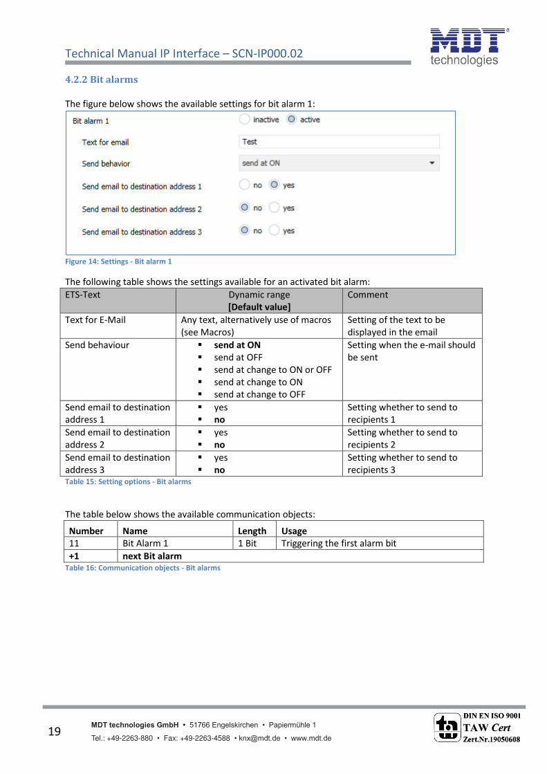
4.2.2 Bit alarms
The figure below shows the available settings for bit alarm 1:
Figure 14: Settings - Bit alarm 1
The following table shows the settings available for an activated bit alarm:
ETS-Text Dynamic range
[Default value]
Comment
Text for E-Mail Any text, alternatively use of macros
(see Macros)
Setting of the text to be
displayed in the email
Send behaviour send at ON
send at OFF
send at change to ON or OFF
send at change to ON
send at change to OFF
Setting when the e-mail should
be sent
Send email to destination
address 1
yes
no
Setting whether to send to
recipients 1
Send email to destination
address 2
yes
no
Setting whether to send to
recipients 2
Send email to destination
address 3
yes
no
Setting whether to send to
recipients 3 Table 15: Setting options - Bit alarms
The table below shows the available communication objects:
Number Name Length Usage
11 Bit Alarm 1 1 Bit Triggering the first alarm bit
+1 next Bit alarm Table 16: Communication objects - Bit alarms

Technical Manual IP Interface – SCN-IP000.02
MDT technologies GmbH • 51766 Engelskirchen • Papiermühle 1
Tel.: +49-2263-880 • Fax: +49-2263-4588 • [email protected] • www.mdt.de 20
Macros
In order to display values in emails, macros can be used. The following macros are available:
$D$ -> If this macro is inserted in the text, so the IP interface replaces this by the device
name.
$T$ -> If this macro is inserted into the text, so the IP interface replaces this to the date
and time at which the e-mail event was triggered.
$Nxx$ -> If this macro is inserted into the text so the IP Interface replace it with the name of
the Status element "xx". Should, e.g. the name of the Status element 11 be displayed, so
must be entered $N11$. For the Status element 1 it is enough to enter $N1$.
$Vxx$ -> If this macro is inserted into the text, so the IP interface replaces this with the
value of Status elements „ . Should, e.g. the value of the Status element 11 be displayed,
so must be entered $V11$. For the Status element 1 it is enough to enter $V1$.
A semicolon creates a line break, or writes the first part before the semicolon in the subject
line of the email.
Examples:
For the following examples the device name MDT is gi e . The status ele ent 1 has the name
"light kitchen" and the data point type 1 bit switching.
1) Texts for E-Mail: $D$ $T$ $N1$ $V1$
A e ail ith the su je t it alarm: MDT ill e sent. The text of the e-mail is:
MDT date-time light kitchen OFF
Since nothing is separated by a semicolon, the whole text is put into the description field of
the e-mail and used for the subject of the default-subject. The macros in the text field will be
replaced by the IP interface and lined up
2) Texts for E-Mail: $D$; $T$; $N1$: $V1$
A e ail ith the su je t MDT ill e se t. The text of the e-mail is:
Date –Time
Light Kitchen: OFF (depending on the current value)
The semicolons separate the name of the device as subject and the text of the email. After
that date, an additional line break is generated.

Technical Manual IP Interface – SCN-IP000.02
MDT technologies GmbH • 51766 Engelskirchen • Papiermühle 1
Tel.: +49-2263-880 • Fax: +49-2263-4588 • [email protected] • www.mdt.de 21
4.2.3 Text alarms
The figure below shows the available settings for the first text-Alarm:
Figure 15: Settings - Text alarm 1
The following table shows the settings available for an activated text alarm:
ETS-Text Dynamic range
[Defaultwert]
Comment
Waiting time until
collected 14 byte
telegrams are sent out
together
1-120s
[10s]
Setting the time window in
which text messages are
combined into one email.
Send email to destination
address 1
yes
no
Setting whether to send to
recipients 1
Send email to destination
address 2
yes
no
Setting whether to send to
recipients 2
Send email to destination
address 3
yes
no
Setting whether to send to
recipients 3 Figure 16: Setting options - Text alarms
A text alarm is triggered as soon as a value is written to the corresponding communication object.
To send longer texts than 14 characters: After sending a value to the corresponding communication
object, the IP interface will wait the set waiting time.
If, within the set waiting time, another string has been sent to the communication object, all
collected strings are sent one after another in the email.
The table below shows the available communication objects:
Number Name Lenght Usage
8 Text alarm 1 1 Bit Setting the value for the text alarm
+1 next Text alarm Table 17: Communication objects - Text alarms

Technical Manual IP Interface – SCN-IP000.02
MDT technologies GmbH • 51766 Engelskirchen • Papiermühle 1
Tel.: +49-2263-880 • Fax: +49-2263-4588 • [email protected] • www.mdt.de 22
4.2.4 Status reports
The figure below shows the available settings for the first status report:
Figure 17: Settings - Status report 1
The following table shows the settings available for an activated status report:
ETS-Text Dynamic range
[Defaultwert]
Comment
Send condition fixed day in the week
fixed date in month
Object „Send status
Setting when the status report
should be sent.
Send email to destination
address 1
yes
no
Setting whether to send to
recipients 1
Send email to destination
address 2
yes
no
Setting whether to send to
recipients 2
Send email to destination
address 3
yes
no
Setting whether to send to
recipients 3
Status element 1-30 not contained in E-Mail
contained in E-Mail
Setting whether the status
element should be displayed in
the email Table 18: Setting options - Status report
The status report can be sent cyclically, once a week or once a month, as well as beeing transmitted
via object.
Each activated Status element can be integrated in the status report. All activated Status elements
are displayed in the status report as follows:
Name of the status element: value of the status element
The table below shows the available communication objects:
Number Name Lenght Usage
8 Status report 1 1 Bit Sending the status report; is displayed only
he the se d o ditio is set to o je t
+1 next Status report Table 19: Communication objects - Status report
Technical Manual IP Interface – SCN-IP000.02
MDT technologies GmbH • 51766 Engelskirchen • Papiermühle 1
Tel.: +49-2263-880 • Fax: +49-2263-4588 • [email protected] • www.mdt.de 23
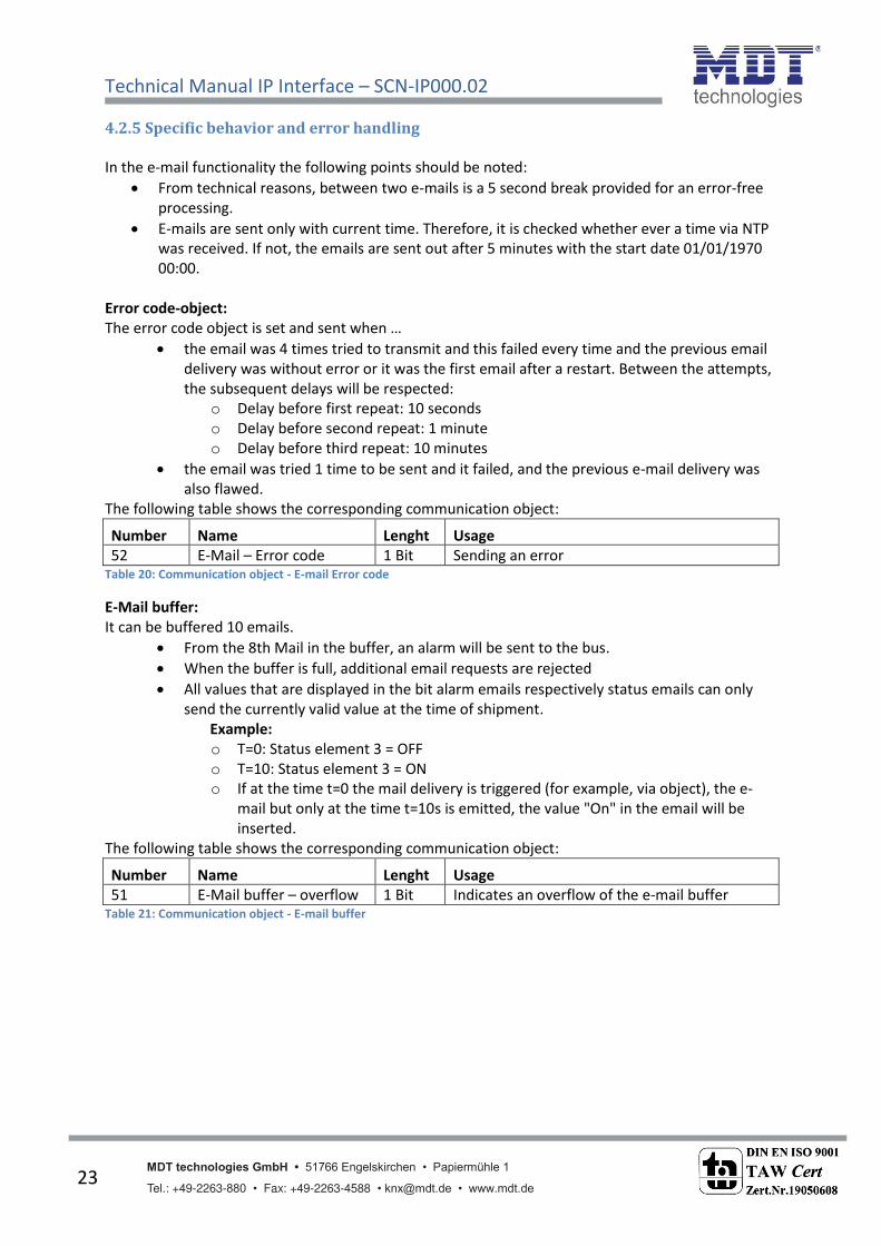
4.2.5 Specific behavior and error handling
In the e-mail functionality the following points should be noted:
From technical reasons, between two e-mails is a 5 second break provided for an error-free
processing.
E-mails are sent only with current time. Therefore, it is checked whether ever a time via NTP
was received. If not, the emails are sent out after 5 minutes with the start date 01/01/1970
00:00.
Error code-object:
The error code object is set and sent when …
the email was 4 times tried to transmit and this failed every time and the previous email
delivery was without error or it was the first email after a restart. Between the attempts,
the subsequent delays will be respected:
o Delay before first repeat: 10 seconds
o Delay before second repeat: 1 minute
o Delay before third repeat: 10 minutes
the email was tried 1 time to be sent and it failed, and the previous e-mail delivery was
also flawed.
The following table shows the corresponding communication object:
Number Name Lenght Usage
52 E-Mail – Error code 1 Bit Sending an error Table 20: Communication object - E-mail Error code
E-Mail buffer:
It can be buffered 10 emails.
From the 8th Mail in the buffer, an alarm will be sent to the bus.
When the buffer is full, additional email requests are rejected
All values that are displayed in the bit alarm emails respectively status emails can only
send the currently valid value at the time of shipment.
Example:
o T=0: Status element 3 = OFF
o T=10: Status element 3 = ON
o If at the time t=0 the mail delivery is triggered (for example, via object), the e-
mail but only at the time t=10s is emitted, the value "On" in the email will be
inserted.
The following table shows the corresponding communication object:
Number Name Lenght Usage
51 E-Mail buffer – overflow 1 Bit Indicates an overflow of the e-mail buffer Table 21: Communication object - E-mail buffer

Technical Manual IP Interface – SCN-IP000.02
MDT technologies GmbH • 51766 Engelskirchen • Papiermühle 1 • Tel.: +49-2263-880 • Fax: +49-2263-4588 • [email protected] • www.mdt.de
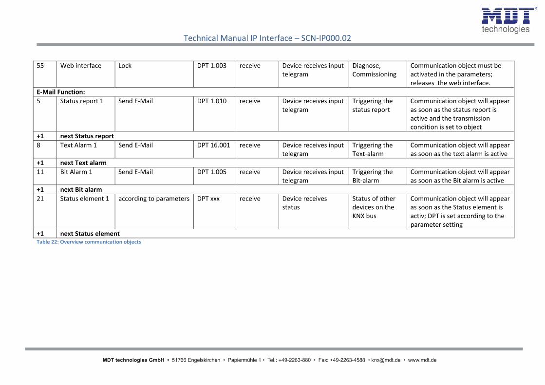
4.3 Overview communication objects
No. Name Object funktion Data point Direction Info Usage Note
allgemeine Objekte:
1 Operation Send status DPT 1.011 send Device sends cyclic
In-operation
telegram
Diagnose Communication object is displayed
once the "cyclic In operation
telegram" was activated.
2 Time Send current time DPT 10.001 send Device sends time Time
synchronization
Communication object is
permanently displayed.
3 Date Send current date DPT 11.001 send Device sends date Time
synchronization
Communication object is
permanently displayed.
4 Date/Time Send current date and
time
DPT 19.001 send Device sends date
and time
Time
synchronization
Communication object is
permanently displayed.
51 E-Mail buffer Overflow DPT 1.005 send Device reports error Diagnose Communication object is
permanently displayed and shows
an email to overflow.
52 E-Mail Error code DPT 1.005 send Device reports error Diagnose Communication object is
permanently displayed and displays
an e-mail transmission error.
53 NTP Time server Error DPT 1.005 send Device reports error Diagnose Communication object is
permanently displayed and
indicates that no time from NTP
time server could be received
54 Webinterface Lock status DPT 1.003 send Device sends Status Diagnose,
Visualisation
Communication object is
permanently displayed and
indicates whether the web interface
is accessible.
Technical Manual IP Interface – SCN-IP000.02
MDT technologies GmbH • 51766 Engelskirchen • Papiermühle 1 • Tel.: +49-2263-880 • Fax: +49-2263-4588 • [email protected] • www.mdt.de
55 Web interface Lock DPT 1.003 receive Device receives input
telegram
Diagnose,
Commissioning
Communication object must be
activated in the parameters;
releases the web interface.
E-Mail Function:
5 Status report 1 Send E-Mail DPT 1.010 receive Device receives input
telegram
Triggering the
status report
Communication object will appear
as soon as the status report is
active and the transmission
condition is set to object
+1 next Status report
8 Text Alarm 1 Send E-Mail DPT 16.001 receive Device receives input
telegram
Triggering the
Text-alarm
Communication object will appear
as soon as the text alarm is active
+1 next Text alarm
11 Bit Alarm 1 Send E-Mail DPT 1.005 receive Device receives input
telegram
Triggering the
Bit-alarm
Communication object will appear
as soon as the Bit alarm is active
+1 next Bit alarm
21 Status element 1 according to parameters DPT xxx receive Device receives
status
Status of other
devices on the
KNX bus
Communication object will appear
as soon as the Status element is
activ; DPT is set according to the
parameter setting
+1 next Status element Table 22: Overview communication objects

Technical Manual IP Interface – SCN-IP000.02
MDT technologies GmbH • 51766 Engelskirchen • Papiermühle 1
Tel.: +49-2263-880 • Fax: +49-2263-4588 • [email protected] • www.mdt.de 26
5 Web-Interface
5.1 Call of the Web-Interface
The web interface can be accessed in 2 types:
1.) Via the Browser:
For this, open your default browser and insert the following address in the address bar:
http:\\ip-address:Port
Example: The following settings are made for the IP interface:
Figure 18: Web-Interface - Example IP Configuration
Here insert http://192.168.1.178:8080 to the address bar.
2.) Go to the Wi do s E plorer a d ope the folder Net ork . Here our IP i terfa e should appear with the specified host name. Double-click on the interface, your default browser is
invoked with the correct address.

Technical Manual IP Interface – SCN-IP000.02
MDT technologies GmbH • 51766 Engelskirchen • Papiermühle 1
Tel.: +49-2263-880 • Fax: +49-2263-4588 • [email protected] • www.mdt.de 27
5.2 Overview Web-Interface
After calling up the web interface, the login window appears:
Figure 19: Web-Interface - Login window
After a successful login, the menus can be selected on the left side. The menus have the following
functions:
Device Info
The menu De i e I fo o tai s i for atio a d setti gs of the IP i terfa es, su h as MAC address, IP address, network settings, software version, etc.
Prog. Mode
I the e u Prog. Mode the progra i g LEDs for the TP a d the IP side can be switched
ON and OFF. Furthermore, the allocated physical addresses, the tunneling addresses and
serial number can be seen.
I the e u E ail the e-mail functionality can be set, see also 5.3 .
Time
I the e u Ti e , information concerning the time server can be viewed.
Firmware Update
It is possible to perform an update for the IP interface. Please contact the MDT support if an
update for your device is available and if so, useful. The MDT Support tells you the steps
required to.

Technical Manual IP Interface – SCN-IP000.02
MDT technologies GmbH • 51766 Engelskirchen • Papiermühle 1
Tel.: +49-2263-880 • Fax: +49-2263-4588 • [email protected] • www.mdt.de 28
5.3 Setting of E-Mail functionality
To set up E-mail functionality, open the menu E-mail and click "Settings":
Figure 20: Web-Interface – Destination E-Mail test
Subsequently, the following menu opens:
Figure 21: Web-Interface – E-Mail settings

Technical Manual IP Interface – SCN-IP000.02
MDT technologies GmbH • 51766 Engelskirchen • Papiermühle 1
Tel.: +49-2263-880 • Fax: +49-2263-4588 • [email protected] • www.mdt.de 29
Now the sending E-mail address and the destination addresses (up to 3) can be set.
The following settings have to be made for the sending email address:
SMTP server address
Here the outgoing mail server has to be specified.
SMTP server port
Here the port is specified for the outgoing mail.
E-Mail Address
Specification of the sending email address.
Username
The name needs to be entered with which you log on to your e-mail address. This can vary
depending on the provider and can be e.g. a complete e-mail address, a user name or an ID.
Password
Enter the password you use to log in to your e-mail address.
Note: The following example is made with the German provider WEB.DE . For details regarding the specifications of other providers (outside Germany) please check with your local provider.
If searching for server data e.g. at web.de, the following data are given:
Figure 22: Example 1 - server data (German)
Thus, i the field „“MTP ser er address the alue „s tp. e .de a e e tered a d i the field „“MTP ser er port the alue „5
At the provider web.de it is further required that the sending of e-mails via external programs needs
to be activated in the settings:
Figure 23: Example 2 - server data (German)

Technical Manual IP Interface – SCN-IP000.02
MDT technologies GmbH • 51766 Engelskirchen • Papiermühle 1
Tel.: +49-2263-880 • Fax: +49-2263-4588 • [email protected] • www.mdt.de 30
In addition to the above described vendor web.de, the following providers are tested with the
settings listet below:
gmx.de
SMTP server adress: mail.gmx.net
SMTP server port: 587
1&1
SMTP server adress: smtp.1und1.de
SMTP server port: 587
Telekom
SMTP server adress: smtpmail.t-online.de
SMTP server port: 465
HotMail, jetzt outlook.com/de
SMTP server adress: smtpmail.live.com
SMTP server port: 587
Strato
SMTP server adress: smtp.strato.de
SMTP server port: 587
All data of the email providers are on the state of the manual, see front page, and are not
guaranteed.
Into the Destination E-mail address i sert all email addresses (max. 3) to which you want to send
an email.
Then you close the menu by the OK button.
In the following menu the e-mail configuration can be tested:
Figure 24: Web-Interface – E-Mail Test
After successful configuration, a test e-mail to the set destination addresses can be triggered.
Then the status is displayed and if so, an error is displayed. The significance of the error codes is
shown in 5.4.
Test E-Mail address 1
Status

Technical Manual IP Interface – SCN-IP000.02
MDT technologies GmbH • 51766 Engelskirchen • Papiermühle 1
Tel.: +49-2263-880 • Fax: +49-2263-4588 • [email protected] • www.mdt.de 31
5.4 E-Mail – Error codes & remedy
Status in the web interface always shows the status of the last sent email. If an error occurs, the error
codes have the following meanings:
Error 0: No error (250 Requested mail action okay, completed: id=0LgK3g-1aIfqB1ZsS-
00nhnX)
o Last E-Mail was sent without problems.
Error 4: unable to connect to server
o Wrong Port specified
Check Port
Error 6: invalid sending Email address
o Sending-E-Mail address is invalid
o Sending-E-Mail address not accepted by server
Check the settings for the E-Mail address
Error 8: invalid receiving Email address
o Destination E-Mail address is invalid
Check destination E-Mail address
Error 9: Socket unexpectedly closed
Restart the device and if necessary reprogram
Error 12: Unknown/unsupported server authentication request (535 Authentication
credentials invalid)
o Invalid username or password
Check username and/or password
5.5 Receive E-Mail as push message
E-mails can be received as a push message to the phone. Therefore, certain services need to be used.
Thus, e.g. be used for Apple devices, the service Prowl: http://www.prowlapp.com/ can be used.
By using push messages, emails are immediately displayed as "Notification" on the device.
5.6 Receive E-Mail as SMS
To convert emails into SMS and send this, a number of providers offer this service in certain packages,
for example, Telekom. If your email provider does not support any SMS-service for e-mails, so third
parties like SMS77 - https://www.sms77.de/ - can be used.

Technical Manual IP Interface – SCN-IP000.02
MDT technologies GmbH • 51766 Engelskirchen • Papiermühle 1
Tel.: +49-2263-880 • Fax: +49-2263-4588 • [email protected] • www.mdt.de 32
6 Index
6.1 Register of illustrations
Figure 1: Structure Hardware module ..................................................................................................... 5
Figure 2: General Settings ....................................................................................................................... 7
Figure 3: IP Configuration 1 ..................................................................................................................... 8
Figure 4: ETS4 – Settings - Communication ........................................................................................... 10
Figure 5: ETS4 - Discovered connections ............................................................................................... 10
Figure 6: ETS4 - Local Settings Interface ............................................................................................... 11
Figure 7: ETS5 - Bus - Interfaces ............................................................................................................ 11
Figure 8: ETS5 - Discovered connections ............................................................................................... 12
Figure 9: ETS5 - Interface Test/Select .................................................................................................... 12
Figure 10: ETS5 - IP Tunneling connection ............................................................................................ 12
Figure 11: Set Tunneling Addresses in "Prog.Mode" ............................................................................ 13
Figure 12: General settings E-Mail Client .............................................................................................. 14
Figure 13: Status elements - 1 byte ....................................................................................................... 18
Figure 14: Settings - Bit alarm 1 ............................................................................................................ 19
Figure 15: Settings - Text alarm 1 .......................................................................................................... 21
Figure 16: Setting options - Text alarms ................................................................................................ 21
Figure 17: Settings - Status report 1 ...................................................................................................... 22
Figure 18: Web-Interface - Example IP Configuration ........................................................................... 26
Figure 19: Web-Interface - Login window ............................................................................................. 27
Figure 20: Web-Interface – Destination E-Mail test .............................................................................. 28
Figure 21: Web-Interface – E-Mail settings ........................................................................................... 28
Figure 22: Example 1 - server data (German)........................................................................................ 29
Figure 23: Example 2 - server data (German)........................................................................................ 29
Figure 24: Web-Interface – E-Mail Test ................................................................................................. 30

Technical Manual IP Interface – SCN-IP000.02
MDT technologies GmbH • 51766 Engelskirchen • Papiermühle 1
Tel.: +49-2263-880 • Fax: +49-2263-4588 • [email protected] • www.mdt.de 33
6.2 List of tables
Table 1: Database for applications .......................................................................................................... 4
Table 2: Overview LEDs ........................................................................................................................... 6
Table 3: General Parameters ................................................................................................................... 7
Table 4: IP Configuration ......................................................................................................................... 8
Table 5: Settings Web-Interface ............................................................................................................ 15
Table 6: Communication object - lock/unlock Web-Interface .............................................................. 15
Table 7: Settings Time/Date .................................................................................................................. 16
Table 8: Communication objects - Time/Date....................................................................................... 16
Table 9: Settings - Status element 1 ...................................................................................................... 17
Table 10: Status elements - 1 Bit ........................................................................................................... 17
Table 11: Status elements - 2 byte ........................................................................................................ 18
Table 12: Status elements - 4 byte ........................................................................................................ 18
Table 13: Status elements - 14 byte ...................................................................................................... 18
Table 14: Communication objects - Status elements ............................................................................ 18
Table 15: Setting options - Bit alarms ................................................................................................... 19
Table 16: Communication objects - Bit alarms ...................................................................................... 19
Table 17: Communication objects - Text alarms ................................................................................... 21
Table 18: Setting options - Status report .............................................................................................. 22
Table 19: Communication objects - Status report................................................................................. 22
Table 20: Communication object - E-mail Error code ........................................................................... 23
Table 21: Communication object - E-mail buffer .................................................................................. 23
Table 22: Overview communication objects ......................................................................................... 25

Technical Manual IP Interface – SCN-IP000.02
MDT technologies GmbH • 51766 Engelskirchen • Papiermühle 1
Tel.: +49-2263-880 • Fax: +49-2263-4588 • [email protected] • www.mdt.de 34
7 Attachment
7.1 Statutory requirements
The above-described devices must not be used with devices, which serve directly or indirectly the
purpose of human, health- or lifesaving. Further the devices must not be used if their usage can
occur danger for humans, animals or material assets.
Do not let the packaging lying around careless, plastic foil/ -bags etc. can be a dangerous toy for kids.
7.2 Routine disposal
Do not throw the waste equipment in the household rubbish. The device contains electrical devices,
which must be disposed as electronic scrap. The casing contains of recyclable synthetic material.
7.3 Assemblage
Risk for life of electrical power!
All activities on the device should only be done by an electrical specialist. The county specific
regulations and the applicable EIB-directives have to be observed.
7.4 Datasheet

MDT USB/IP Interface
SCN-USBR.01 SCN-LK001.01
MDT Interface, MDRC
Version
SCN-USBR.01 USB Interface 2SU MDRC
SCN-IP000.02 IP Interface 2SU MDRC
SCN-IP100.02 IP Interface with Routing 2SU MDRC
SCN-LK001.01 Line Coupler 2SU MDRC
MDT technologies offers four KNX Interfaces to enable communication between PC and the KNX/EIB system.
KNX USB Interface: The USB Interface enables the communication between the PC and the KNX/EIB system.
The USB interface is galvanically isolated from the KNX/EIB bus.
KNX IP Interface: The IP Interface enables the communication between the PC and the KNX/EIB system via LAN.
4 simultaneous connections possible.
KNX IP Interface with routing: This interface offers the same functions as the IP Interface, but the device routes
telegrams as a line/area coupler using the the LAN.
KNX IP Line Coupler: The Line Coupler connects two KNX lines to each other. Electrical isolation between the lines and
reduction of the busload by using the ilter function.
The MDT KNX Interfaces are modular installation devices for ixed installation in dry rooms. They it on DIN 35mm rails in power distribution boards or closed compact boxes.
For project design and commissioning of the MDT KNX Interfaces it is recommended to use the ETS.
Please download the application software at www.mdt.de/Downloads.html
• Production in Germany, certiied according to ISO 9001
USB Interface:
• To enable bidirectional communication between PC
and the KNX bus via USB
• Fully compatible to ETS3f/4• Long frame support for ETS5
IP Interface:
• To enable bidirectional communication between PC
and the KNX bus TCP/IP
• 4 simultaneous connections possible• Long frame support for ETS5• Programming the KNX bus via TCP/IP• Power supply by KNX bus, no external bus power supply required• Encrypted transmission at sending emails• Time server functions to send time and date on the KNX bus• Modular installation device for DIN 35mm rails• Integrated bus coupling unit • 3 years warranty
SCN-IP100.02 SCN-IP000.02
MDT technologies GmbH • 51766 Engelskirchen • Papiermühle 1
Tel.: + 49 - 2263 - 880 • Fax: + 49 - 2263 - 4588 • [email protected] • www.mdt.de
Stand: 0316
DIN EN ISO 9001
TAW Cert
Zert.Nr.1905606
N

MDT USB/IP Interface
Technical Data SCN-USBR.01 SCN-IP000.02 SCN-IP100.02 SCN-LK001.01
Interface USB Ethernet Ethernet KNX
Speciication KNX interface TP-256 TP-256 TP-256 TP-256
Available application software ETS 3/4/5 with long frame support for ETS5
Permitted wire gauge
Screw terminal --0,5 - 4,0mm² solid core
0,5 - 2,5mm² inely stranded--
KNX busconnection terminal 0,8mm Ø, solid core 0,8mm Ø, solid core 0,8mm Ø, solid core 0,8mm Ø, solid core
Power Supply KNX bus KNX bus KNX bus KNX bus
Power consumption < 0,3W < 0,8W < 0,8W < 0,3W each line
Operation temperature range 0 to + 45°C 0 to + 45°C 0 to + 45°C 0 to +45°C
Enclosure IP 20 IP 20 IP 20 IP 20
Dimensions MDRC (Space Units) 2SU 2SU 2SU 2SU
MDT technologies GmbH • 51766 Engelskirchen • Papiermühle 1
Tel.: + 49 - 2263 - 880 • Fax: + 49 - 2263 - 4588 • [email protected] • www.mdt.de
Stand: 0316
DIN EN ISO 9001
TAW Cert
Zert.Nr.1905606
N