tb404 series conductivity sensors toroidal - abb group · pdf filepr3 - hot tap assemblies pr4...
TRANSCRIPT

User Guide OI/TB404-EN Rev. A (PN25120)
TB404 seriesConductivity sensorsToroidal

The CompanyWe are an established world force in the design and manufacture of measurement products for industrial process control, flow measurement, gas and liquid analysis and environmental applications.
As a part of ABB, a world leader in process automation technology, we offer customers application expertise, service and support worldwide.
We are committed to teamwork, high quality manufacturing, advanced technology and unrivalled service and support.
The quality, accuracy and performance of the Company’s products result from over 100 years experience, combined with a continuous program of innovative design and development to incorporate the latest technology.
EN ISO 9001:2008
Cert. No. Q 05907
EN 29001 (ISO 9001)
Lenno, Italy – Cert. No. 9/90A
Stonehouse, U.K.
����

Trademarks and Registrations
Registrations and trademarks used in this document include:
® Mylar
® Viton
® Tri-Clamp
™ PEEK
Registered trademark of E.I. DuPont de Nemours Company, Incorporated
Registered trademark of E.I. DuPont de Nemours Company, Incorporated
Registered trademark of Alfa Laval, Incorporated
Trademark of Victrex plc.

Preface
This publication is for the use of technical personnel responsible for installa-tion of the ABB Type TB404 Toroidal Conductivity Sensor.
This instruction contains hardware installation instructions only. Wiring pro-cedures, calibration procedures, etc., are covered in product instructions ofinstruments compatible with the Type TB404 sensor.
Some sections of this instruction have been prepared in procedure format.By treating each task as a separate entity, the procedures provide an easymethod for finding the information needed to perform each task. The proce-dures can be removed and placed in separate folders or notebooks, or carriedto the job site.
The procedures have check boxes in the margin by each step. When per-forming a procedure, check each box as each step is completed.
It is important for safety and operation that this instruction be read andunderstood before attempting anything related to installation, operation,maintenance or repair.

List of Effective Pages
Total number of pages in this instruction is 35, consisting of the following:
Page No. Change Date
Preface OriginalList of Effective Pages September 11, 2006
iii through vi August 23, 20061-1 through 1-6 August 23, 20062-1 through 2-3 Original3-1 Original4-1 August 23, 2006
PR1-1 through PR1-2 August 23, 2006PR2-1 through PR2-3 August 23, 2006PR3-1 through PR3-5 August 23, 2006PR4-1 through PR4-2 August 23, 2006PR5-1 through PR5-3 August 23, 2006PR6-1 through PR6-2 August 23, 2006
Index-1 Original
When an update is received, insert the latest changed pages and dispose of the superseded pages.

Table of Contents
Page
i
SECTION 1 - INTRODUCTION....................................................................................................1-1OVERVIEW .....................................................................................................................................................1-1INTENDED USER...........................................................................................................................................1-1SENSOR DESCRIPTION ................................................................................................................................1-1SENSOR APPLICATION................................................................................................................................1-1INSTRUCTION CONTENT ............................................................................................................................1-2HOW TO USE THIS INSTRUCTION ............................................................................................................1-2REFERENCE DOCUMENTS..........................................................................................................................1-2NOMENCLATURE .........................................................................................................................................1-3SPECIFICATIONS...........................................................................................................................................1-4ACCESSORIES................................................................................................................................................1-6
SECTION 2 - INSTALLATION .....................................................................................................2-1INTRODUCTION ............................................................................................................................................2-1UNPACKING AND INSPECTION.................................................................................................................2-1LOCATION CONSIDERATIONS ..................................................................................................................2-1INSTALLATION PROCEDURES ..................................................................................................................2-3
SECTION 3 - REPAIR AND REPLACEMENT.............................................................................3-1INTRODUCTION ............................................................................................................................................3-1
SECTION 4 - SUPPORT SERVICES...........................................................................................4-1INTRODUCTION ............................................................................................................................................4-1REPLACEMENT PARTS................................................................................................................................4-1
PROCEDURESPR1 - SUBMERSIBLE ASSEMBLY PR2 - IN-LINE FLOW ASSEMBLYPR3 - HOT TAP ASSEMBLIESPR4 - TWO-INCH SANITARY TRI-CLAMP ASSEMBLY PR5 - REMOVING SENSOR FROM HOT TAP ASSEMBLIESPR6 - SENSOR CLEANING
List of Figures
No. Title Page
2-1. Type TB4042 Sensor ................................................................................................................................2-22-2. Sensor Orientation Requirements .............................................................................................................2-3PR1-1 Submersible Assembly ........................................................................................................................PR1-2PR2-1 In-Line Assembly, Exploded View......................................................................................................PR2-2PR2-2 In-Line Assembly in Pipe or Tank Fitting ...........................................................................................PR2-3PR3-1 Low Pressure Hot Tap Assemblies ......................................................................................................PR3-4PR3-2 High Pressure Hot Tap Assembly........................................................................................................PR3-5PR4-1 Sanitary In-Line Flow Assembly.........................................................................................................PR4-2PR4-2 Sanitary In-Line Flow Assembly with Tri-Clamp ...............................................................................PR4-2PR5-1 Low Pressure Hot Tap Assemblies ......................................................................................................PR5-2

List of Figures (continued)
No. Title Page
ii
PR5-2 High Pressure Hot Tap Assembly ........................................................................................................PR5-3
List of Tables
No. Title Page
1-1. Reference Documents .............................................................................................................................. 1-21-2. Nomenclature........................................................................................................................................... 1-31-3. Specifications........................................................................................................................................... 1-41-4. Accessories1 ............................................................................................................................................ 1-62-1. Installation Procedures............................................................................................................................. 2-3

iii
Safety Summary
SPECIFICWARNINGS
Always use the sensor guide when using the high pressure hot tapassembly. The sensor guide is a tightly toleranced 1½ in.NPT nipplethat prevents adverse play between the insertion rod and the sensorguide. Adverse play could damage the insertion rod and injure per-sonnel. (p. PR3-2)
Never stand directly behind the insertion rod upon pressurization. Ifthe insertion rod is not fully retracted upon pressurization, it couldrapidly reach the blow out protection of the sensor assembly andseverely injure personnel standing too close behind the insertionrod. (p. PR3-2)
Never exceed the sensor or sanitary clamp temperature and pres-sure limits. Exceeding these limits can damage the equipment insuch a way as to pose the risk of injury to personnel. (p. PR4-1)
Firmly hold the insertion rod when loosening the compression fitting.When the compression rod is loosened, the pressure against the sen-sor assembly will cause the insertion rod to retract from the ball valveassembly with great velocity. This could injure personnel standing inthe path of the retracting insertion rod. Allow only properly trainedpersonnel to handle these types of sensor assemblies. (p. PR5-1)
Open one of the flushing ports after the sensor is retracted and theball valve is closed. If a continuous stream of liquid exists, damageto the ball valve or components can occur or may have alreadyoccurred. This condition can cause a hazard to personnel uponremoval of the insertion rod. (p. PR5-1)
Consider the material compatibility between cleaning fluids and pro-cess liquids. Incompatible fluids can react with each other causinginjury to personnel and equipment damage. (p. PR6-1)
Acids and bases can cause severe burns. Use hand and eye pro-tection when handling. (p. PR6-1)
Use solvents only in well ventilated areas. Avoid prolonged orrepeated breathing of vapors or contact with skin. Solvents cancause nausea, dizziness and skin irritation. In some cases, over-exposure to solvents has caused nerve and brain damage. Sol-vents are flammable - do not use near extreme heat or openflame. (p. PR6-1)

iv
Safety Summary (continued)
THIS PAGE INTENTIONALL LEFT BLANK

OVERVIEW 1 - 1
SECTION 1 - INTRODUCTION
OVERVIEW
The Type TB404 Toroidal Conductivity Sensor Series monitors a wide vari-ety of process liquids. The robust, encapsulated design of the sensor protectsthe internal electronics from corrosive process solutions.
This instruction contains information on sensor installation only. For infor-mation on maintenance, testing, troubleshooting, calibration and repair, referto the product instruction of the analyzer or transmitter used with the sensor.
INTENDED USER
This instruction is intended for use by technical personnel responsible for theinstallation of the Type TB404 sensor.
SENSOR DESCRIPTION
The Type TB404 sensor employs an encapsulated design that makes it idealfor aggressive and harsh process streams. The analyzers and transmitters forwhich the sensor was designed measure moderate to high conductivitystreams.
The sensor is available with a submersible adapter that accommodates sub-mersible installations such as tanks and open vessels or waterways. Thein-line flow assembly provides installation capability for pipelines and tanks.There are also two types of hot tap assemblies available: Low pressure unitswith either hand or wrench-tight compression fittings and high pressureunits. The high pressure units can be ordered with ball valves. Ball valves forlow pressure units must be ordered separately. Finally, there is a two-inchsanitary sensor that provides installation capability for sanitary pipelines andtanks with two-inch tri-clamp fittings.
SENSOR APPLICATION
The Type TB404 sensor is intended to provide measurements for processmonitoring and/or control applications.
Some typical applications include the measurement for display and controlof the conductivity of process fluid streams, boilers, pulping and sugarliquor, concentrated chemical streams, clean-in-place systems, food andpharmaceutical systems, brine, and solutions with heavy solids or high ionicstrength liquids.
INSTRUCTION CONTENT
This instruction consists of four sections and a set of procedures. Afterbecoming completely familiar with it and the sensor, it can be used as a ref-erence.

INTRODUCTION
HOW TO USE THIS INSTRUCTION1 - 2
Introduction Provides a product overview, a description of the sensor and its applicationsand a description of this instruction and how to use it. This section also has alist of reference documents on related equipment and subjects, the productidentification (nomenclature) and a comprehensive list of specifications andaccessories.
Installation Contains unpacking and inspection instructions, and location considerations.Included under location considerations are installation guidelines to followfor proper installation of the sensor. Following this information is a table thatguides installation personnel to the appropriate installation procedures.
Repair and Replacement Contains procedures for removing the sensor from the hot tap hardwareassemblies and cleaning the sensor.
Support Services Contains spare and replacement parts information as well as information oncustomer support.
HOW TO USE THIS INSTRUCTION
Read this entire instruction in sequence before attempting to install, maintainor repair the sensor. After gaining a complete understanding of this instruc-tion and the sensor, it can be used as a reference.
The installation section of this instruction has been prepared in procedureformat. Table 2-1 directs installation personnel to the appropriate procedure.By treating each task as a separate entity, the procedures provide an easymethod for finding the information needed to perform each task. The proce-dures can be removed and placed into separate folders or notebooks and car-ried to the job site.
REFERENCE DOCUMENTS
Table 1-1 lists the ABB documents to be used in conjunction with thisinstruction.
Table 1-1. Reference Documents
Number DocumentC-E67-23-1 Conductivity/Resistivity Sensors for Process Monitoring
D-NCC-TB404 Type TB404 Toroidal Conductivity Sensor Specification
I-E67-82-4A TB82TC Toroidal Conductivity Transmitter
I-E67-84-4 TB84TC Toroidal Conductivity Analyzer
D-NCA-TB82 TB82 Data Sheet
D-NCA-TB84TC TB84TC Data Sheet
D-NCC-TB4043 Type TB4043 Toroidal Conductivity Sensor Specification

INTRODUCTION
NOMENCLATURE 1 - 3
NOMENCLATURE
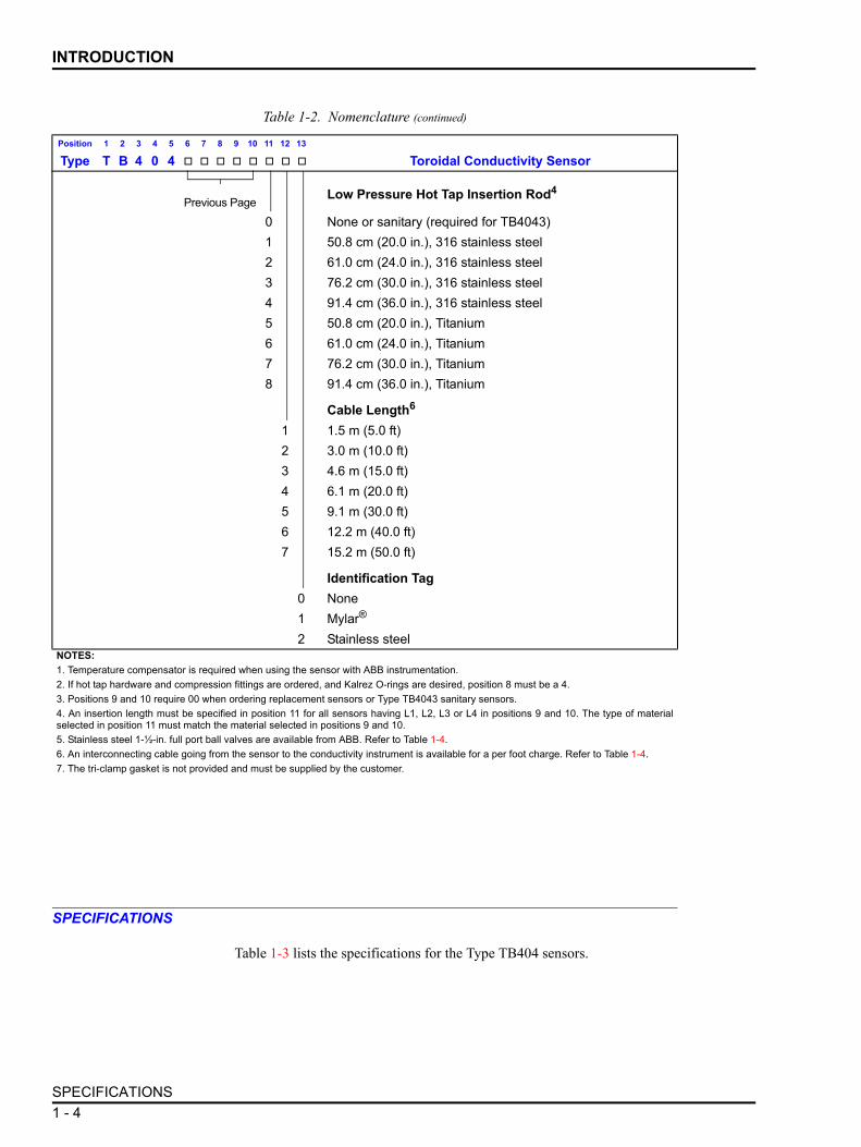
Table 1-2 lists the nomenclature for the Type TB404 sensor.
Table 1-2. Nomenclature
Position 1 2 3 4 5 6 7 8 9 10 11 12 13
Type T B 4 0 4 Toroidal Conductivity Sensor
Next Page Sensor Style
2 Standard with -20 threads, PEEK encapsulated3 Sanitary, 2-in. tri-clamp, PEEK encapsulated with stainless
steel backing
Integral Temperature compensator2 Pt 1000Ω RTD1
O-ring Material0 None (TB4043 only — no O-ring required)1 EPDM (TB4042 only)2 Viton® (TB4042 only)3 Kalrez (for flow, submersible or replacement TB4042 only)4 Kalrez (for hot tap TB4042 only)
Hardware2,3,5
0 0 None (TB4043)3,7
S 1 Submersible adapter, ¾ in. NPT, CPVCS 2 Submersible adapter, ¾ in. NPT, 316 stainless steelS 3 Submersible adapter, ¾ in. NPT, KynarF 1 In-line flow, 1-½ in. NPT, CPVCF 2 In-line flow, 1-½ in. NPT, 316 stainless steelF 3 In-line flow, 1-½ in. NPT, TitaniumL 1 Low pressure hot top without ball valve, wrench tight com-
pression fitting, 316 stainless steel2
L 2 Low pressure hot top without ball valve, hand tight compres-sion fitting, 316 stainless steel2
L 3 Low pressure hot top without ball valve, wrench tight com-pression fitting, Titanium2
L 4 Low pressure hot top without ball valve, hand tight compres-sion fitting, Titanium2
H 1 High pressure hot tap with ball valve, 316 stainless steel2
H 2 High pressure hot top without ball valve, 316 stainless steel2
H 3 High pressure hot tap without ball valve, Titanium2
1516⁄
INTRODUCTION
SPECIFICATIONS1 - 4
SPECIFICATIONS
Table 1-3 lists the specifications for the Type TB404 sensors.
Previous PageLow Pressure Hot Tap Insertion Rod4
0 None or sanitary (required for TB4043)1 50.8 cm (20.0 in.), 316 stainless steel2 61.0 cm (24.0 in.), 316 stainless steel3 76.2 cm (30.0 in.), 316 stainless steel4 91.4 cm (36.0 in.), 316 stainless steel5 50.8 cm (20.0 in.), Titanium6 61.0 cm (24.0 in.), Titanium7 76.2 cm (30.0 in.), Titanium8 91.4 cm (36.0 in.), Titanium
Cable Length6
1 1.5 m (5.0 ft)2 3.0 m (10.0 ft)3 4.6 m (15.0 ft)4 6.1 m (20.0 ft)5 9.1 m (30.0 ft)6 12.2 m (40.0 ft)7 15.2 m (50.0 ft)
Identification Tag0 None1 Mylar®
2 Stainless steelNOTES:1. Temperature compensator is required when using the sensor with ABB instrumentation.2. If hot tap hardware and compression fittings are ordered, and Kalrez O-rings are desired, position 8 must be a 4.3. Positions 9 and 10 require 00 when ordering replacement sensors or Type TB4043 sanitary sensors.4. An insertion length must be specified in position 11 for all sensors having L1, L2, L3 or L4 in positions 9 and 10. The type of materialselected in position 11 must match the material selected in positions 9 and 10.5. Stainless steel 1-½-in. full port ball valves are available from ABB. Refer to Table 1-4.6. An interconnecting cable going from the sensor to the conductivity instrument is available for a per foot charge. Refer to Table 1-4.7. The tri-clamp gasket is not provided and must be supplied by the customer.
Table 1-2. Nomenclature (continued)
Position 1 2 3 4 5 6 7 8 9 10 11 12 13
Type T B 4 0 4 Toroidal Conductivity Sensor

INTRODUCTION
SPECIFICATIONS1 - 5
Table 1-3. Specifications
Property Characteristic/ValueTB4042??F
Range1 Minimum 0 to 400 microsiemens (μS), maximum 0 to 2,000 millisiemens (mS)
Pressure2 2,068 kPa (300 psig) with 316 stainless steel adapter
2,068 kPa (300 psig) with Titanium adapter
689 kPa (100 psig) with CPVC adapter
Temperature2 200°C (392°F) with 316 stainless steel adapter
200°C (392°F) with Titanium adapter
65°C (149°F) with CPVC adapter
TB4042??H
Range1
Pressure2
Temperature2
Seals
Materials
Process connection
Minimum 0 to 400 μS, maximum 0 to 2,000 mS
2,068 kPa (300 psig)
150°C (302°F)
Teflon®* ferrule in compression fitting, O-rings per sensor nomenclature
316 stainless steel and Titanium
1½ in. NPT with ABB supplied ball valve (Titanium ball valve supplied by customer)
TB4042??L
Range1
Pressure2
Temperature2
Seals
Materials
Process connection
Minimum 0 to 400 μS, maximum 0 to 2,000 mS
689 kPa (100 psig)
150°C (302°F)
Teflon®* ferrule in compression fitting, O-rings per sensor
nomenclature 316 stainless steel and Titanium
Minimum 1½ in. NPT depending on type of ball valve chosen
TB4042??S
Range1 Minimum 0 to 400 μS, maximum 0 to 2,000 mS
Pressure2 689 kPa (100 psig) with 316 stainless steel adapter
689 kPa (100 psig) with CPVC adapter
689 kPa at 80°C (100 psig at 176°F)
276 kPa at 140°C (80 psig at 284°F) with Kynar adapter
Temperature2 200°C (392°F) with 316 stainless steel adapter
80°C (176°F) with CPVC adapter
140°C at 276 kPa (284°F at 40 psig)
80°C at 689 kPa (176°F at 100 psig) with Kynar adapter
TB4043
Range1 Minimum 0 to 400 μS, maximum 0 to 2,000 mS
Pressure2 2068 kPa (300 psig)
Temperature2 200°C (392°F)NOTES:1. Range depends on conductivity instrument used.2. Maximum pressure and temperature ratings may vary according to required hardware.
SPECIFICATIONS ARE SUBJECT TO CHANGE WITHOUT NOTICE.
* TEFLON® is a registered trademark of DuPont.

INTRODUCTION
ACCESSORIES1 - 6
ACCESSORIES
Table 1-4 lists the accessories available for use with the Type TB404 sen-sors.
Table 1-4. Accessories1
Accessory Description4TB3004-0008 Interconnecting cable, Teflon®* jacketed, 6-conductor, sensor to conductivity instrument4TB4711-0021 Retaining nut for in-line flow assembly4TB4906-0014 Viton gasket for in-line flow assembly4TB4951-0092 Submersible coupling adapter ( -20 x ¾ in. NPT), CPVC4TB4951-0093 Submersible coupling adapter ( -20 x ¾ in. NPT), Kynar4TB4951-0094 Submersible coupling adapter ( -20 x ¾ in. NPT), 316 stainless steel4TB5110-0067 Conduit/cable gland adapter for in-line flow assembly, ¾ in.4TB5205-0285 Full port ball valve, 1-½ in., 316 stainless steel4TB8006-0025 High temperature silicone grease4TB8006-0045 Anti-seize compound4TB9515-0065 Hardware kit for high pressure hot tap assembly with Titanium hardware and EPDM hard-
ware O-rings (Nos. 014 and 132)4TB9515-0066 Hardware kit for high pressure hot tap assembly with Titanium hardware and Viton hard-
ware O-rings (Nos. 014 and 132)4TB9515-0067 Hardware kit for high pressure hot tap assembly with Titanium hardware and Kalrez hard-
ware O-rings (Nos. 014 and 132)4TB9515-0069 Hardware kit for high pressure hot tap assembly with 316 stainless steel hardware and
EPDM hardware O-rings (Nos. 014 and 132)4TB9515-0070 Hardware kit for high pressure hot tap assembly with 316 stainless steel hardware, EPDM
hardware O-rings (Nos. 014 and 132) and ball valve4TB9515-0071 Hardware kit for high pressure hot tap assembly with 316 stainless steel hardware and
Viton hardware O-rings (Nos. 014 and 132)4TB9515-0072 Hardware kit for high pressure hot tap assembly with 316 stainless steel hardware, Viton
hardware O-rings (Nos. 014 and 132) and ball valve4TB9515-0073 Hardware kit for high pressure hot tap assembly with 316 stainless steel hardware and
Kalrez hardware O-rings (Nos. 014 and 132)4TB9515-0074 Hardware kit for high pressure hot tap assembly with 316 stainless steel hardware, Kalrez
hardware O-rings (Nos. 014 and 132) and ball valve4TB9515-0104 In-line fitting for in-line flow assembly, 1-½ in., 316 stainless steel4TB9515-0105 In-line fitting for in-line flow assembly, 1-½ in., Titanium4TB9515-0106 In-line fitting for in-line flow assembly, 1-½ in., CPVC4TB9515-0107 Sensor O-ring kit (No. 117), EPDM4TB9515-0108 Sensor O-ring kit (No. 117), Viton4TB9515-0109 Sensor O-ring kit (No. 117), KalrezNOTE:1. Most accessories are available as nomenclature options or come installed with sensor assemblies. Refer to Table 1-2.
1516⁄
1516⁄
1516⁄
* TEFLON® is a registered trademark of DuPont.

INTRODUCTION 2 - 1
SECTION 2 - INSTALLATION
INTRODUCTION
This section contains unpacking and inspection instructions, and speciallocation and safety considerations.
Following these topics is a table that guides personnel, seeking to perform aspecific installation task, to the proper procedure or procedures needed toperform that task.
NOTE: Sensor wiring procedures are located in the product instruc-tion of the analyzer or transmitter used with the sensor.
UNPACKING AND INSPECTION
Examine the equipment upon receipt for possible damage in transit. If thereis evidence of damage, file a damage claim with the responsible transporta-tion company and notify the nearest ABB sales office.
Carefully inspect the packing material before discarding it to make certainthat all mounting equipment and any special instructions or paperwork havebeen removed. Careful handling and installation insures satisfactory perfor-mance of the sensor.
Use the original packing material and container for storage. The storageenvironment should be protected and free from extremes in temperature andhumidity and fall within the environmental specifications listed in Table 1-3.
LOCATION CONSIDERATIONS
The Type TB404 sensor employs an encapsulated design that makes it idealfor aggressive and harsh process streams. Sensor variations accommodatesubmersible installations such as tanks and open vessels or waterways, pipe-lines, and sanitary pipelines and tanks with two-inch tri-clamp fittings. Fig-ure 2-1 shows the anatomy of the Type TB4042 sensor.
When installing the sensor, choose a location that insures the following:
• The solution around the sensing area (Fig. 2-1) must be representativeof the bulk solution.
• The fluid velocity must not damage the sensing area either by cavitationor abrasion.
• The solution must actively circulate through and around the sensing areaand must not contain entrained air or vapors.
• The sensing area must be perpendicular to the fluid flow path. Figure2-2 shows the sensor orientation requirements.

INSTALLATION
LOCATION CONSIDERATIONS2 - 2
• The sensing area must be completely immersed into the fluid (Fig. 2-2).Partial and varying immersion will cause measurement errors.
• The sensor position within the process pipe or any container during cal-ibration must not cause air entrapment around the sensing area.
• The sensor cable should be housed in a flexible type of metal or shieldedconduit to minimize the effects of radio frequency interference (RFI)and electromagnetic interference (EMI). Submersion sensors requirenonflexible piping or conduit.
• The sensor position must not allow accumulation of excess sediment orother foreign material around the sensing area.
• The sensor position must insure that the internal temperature sensor isfacing into the fluid flow path.
NOTE: The temperature sensor is located at the sensing area onthe same side as the embossed PEEK insignia (Fig. 2-1).
• Lubricate all O-rings with a silicone grease or equivalent before assem-bling the sensor into the installation hardware.
Figure 2-1. Type TB4042 Sensor
PEEK
T00872A
FLAT INDICATES SENSINGAREA ORIENTATION
TEMPERATURE SENSORLOCATION
O-RINGS
PEEKBODY
SENSORBORE
SENSINGAREA(DONUT)
15/16-20THREADS
116.84.60
36.11.42
DIMENSIONSMILLIMETERS
INCHES

INSTALLATION
INSTALLATION PROCEDURES 2 - 3
INSTALLATION PROCEDURES
Table 2-1 lists the installation procedures for the various sensor hardwaretypes.
Figure 2-2. Sensor Orientation Requirements
SENSINGAREAPARALLELTOFLOW
FLUIDLEVEL BELOW
SENSINGAREAPERPENDICULARTOFLOW
FLOW
FLUIDLEVEL
FLUIDLEVEL ABOVE
FLUIDLEVEL
PEEK
PEEKPEEK
FLOW
SENSINGAREA
Table 2-1. Installation Procedures
Description ProcedureSubmersible assembly PR1
In-line flow assembly PR2
Hot top assemblies PR3
Two-inch sanitary in-line flow assembly PR4

INTRODUCTION 3 - 1
SECTION 3 - REPAIR AND REPLACEMENT
INTRODUCTION
This section does not contain repair instructions for the Type TB404 Toroi-dal Conductivity Sensor. Due to the nature of its design, complete sensorreplacement is required when it has been damaged or does not properly func-tion. Contact ABB for replacement toroidal conductivity sensors.
If using a high or low pressure hot tap assembly, the sensor must be removedfrom the hot tap hardware for replacement or service. Refer to PR5 for theprocedure. PR6 contains the sensor cleaning procedures.

INTRODUCTION 4 - 1
SECTION 4 - SUPPORT SERVICES
INTRODUCTION
When ordering replacement parts, specify nomenclature type, part name andpart number.
ABB is ready to assist in the use and repair of its products at any time.Requests for sales and/or application service should be made to the nearestsales or service office.
Factory support in the use of the Type TB404 Toroidal Conductivity Sensorcan be obtained by contacting:
ABB Inc.9716 S. Virginia St., Ste EReno, NV 89511 USAPhone: +1 (775) 850 4800Fax: +1 (775) 850 4808www.abb.com/instrumentation
REPLACEMENT PARTS
When making repairs at your facility, order spare parts from a ABB salesoffice. Provide this information.
1. Spare part description, part number and quantity.
2. Model and serial number (if applicable).
3. ABB instruction manual number, page number and reference figure thatidentifies the part.
Contact ABB for replacement toroidal conductivity sensors. Table 1-4 liststhe accessories available for the sensor. This table also applies to spare andreplacement parts. When ordering standard parts from ABB, use the partnumbers and descriptions from Table 1-4. Order parts without commercialdescriptions from the nearest ABB sales office.

PURPOSE/SCOPEPR1 - 1
PROCEDURE PR1 - SUBMERSIBLE ASSEMBLY
PURPOSE/SCOPE
This procedure explains how to install the submersible assembly.
Parts
Tools None.
PROCEDURE
The submersible adapter allows installation of the Type TB4042 sensor intosubmersible installations such as tanks and open vessels or waterways.
1. Lightly lubricate the sensor O-rings with high temperature siliconegrease or equivalent.
2. Attach the sensor to the submersible coupling adapter as shown in Fig-ure PR1-1.
3. Place pipe sealant, Teflon®* tape or equivalent onto the ¾ in. NPT malethreads of the submersible coupling adapter.
NOTE: ABB recommends the application of pipe sealant, Teflon®* tape or equivalent onto all pipe threads to prevent process liquids from seeping into the conduit piping.
4. Attach the ¾ in. NPT pipe coupling to the submersible coupling adapter.
20 min.
Number Qty Description4TB4951-0092 1 Submersible coupling adapter,
( -20 x ¾ in. NPT), CPVC
4TB4951-0093 Submersible coupling adapter,( -20 x ¾ in. NPT), Kynar
4TB4951-0094 Submersible coupling adapter,( -20 x ¾ in. NPT), 316 stainless steel
4TB8006-0025 A/R Silicone grease, high temperature
Customer-supplied 1 Conduit pipe
Customer-supplied 1 Pipe coupling, ¾ in. NPT
Customer-supplied A/R Pipe sealant, Teflon®* tape, or equivalent
Customer-supplied A/R Coupling and cable gland, or caulk
Customer-supplied A/R Conduit clamp or similar device
1516⁄
1516⁄
1516⁄
A/R = as required
* TEFLON® is a registered trademark of DuPont.

PROCEDUREPR1 - 2
5. Attach a section of conduit pipe to the pipe coupling. This sectionshould be long enough to position the sensor in the desired location withinthe tank, vessel or trough to meet the installation guidelines described inSection 2.
6. Use a coupling and cable gland, or caulk to seal the area around the sen-sor cable and top of the conduit pipe to prevent moisture from entering thepipe.
7. Position the pipe in the desired location and retain it in a fixed positionusing a conduit clamp or similar device.
8. Orient the sensor in the flow according to the installation guidelinesdescribed in Section 2.
Figure PR1-1. Submersible Assembly
USER-SUPPLIEDCONDUIT PIPE
USER-SUPPLIEDCOUPLING
T00874A
SUBMERSIBLE COUPLINGADAPTER(PURCHASEDSEPARATELY ORTHROUGHNOMENCLATURE)
3/4-IN.NPTMALETHREAD
PEEK

PURPOSE/SCOPE PR2 - 1
PROCEDURE PR2 - IN-LINE FLOW ASSEMBLY
PURPOSE/SCOPE
This procedure explains how to install the in-line flow assembly.
Parts
Tools • Two-inch open-end wrench.• -inch open-end wrench.• 1½-inch open-end wrench.
PROCEDURE
The in-line flow assembly provides installation capability for pipelines andtanks.
1. Lightly lubricate the No. 117 O-rings (Fig. PR2-1) with high tempera-ture silicone grease or equivalent.
2. Install the sensor into the 1½-inch in-line fitting.
3. Thread the retaining nut onto the sensor. Hand-tighten it only to allowfor adjustment when the assembly is installed into the pipeline or tank.
4. Apply high temperature pipe sealant onto the outer threads of the in-linefitting.
5. Install the in-line fitting into the pipe or tank fitting using a two-inchopen-end wrench to tighten the fitting (Fig. PR2-2).
NOTE: The pipe or tank fitting must have a female 1½-NPT thread
20 min.
Number Qty Description4TB4711-0021 1 Nut, retaining
4TB4906-0014 1 In-line gasket, Viton
4TB4951-0085 1 In-line fitting, 1½-in., 316 stainless steel
4TB4951-0087 In-line fitting, 1½-in., CPVC
4TB4951-0088 In-line fitting, 1½-in., Titanium
4TB5110-0067 1 Conduit/cable gland adapter, ¾ in.
4TB8006-0025 A/R Silicone grease, high temperature
4TB9515-0107 2 O-ring, No. 117, EPDM
4TB9515-0108 O-ring, No. 117, Viton
4TB9515-0109 O-ring, No. 117, Kalrez
Customer-supplied A/R High temperature pipe sealant
Customer-supplied A/R Flexible conduit or cable gland
916⁄
A/R = as required

PROCEDUREPR2 - 2
6. Using the -inch open-end wrench on the wrench flats on the sensor,rotate the sensor so that the sensing area is perpendicular to the flow path tomeet the installation guidelines described in Section 2.
7. While maintaining the sensor orientation with the -inch open-endwrench, use a 1½-inch open-end wrench to tighten the retaining nut.
8. Slide the Viton gasket over the back of the sensor and onto the retainingnut.
Figure PR2-1. In-Line Assembly, Exploded View
ASSEMBLEDIN-LINESENSOR T00876A
3/4-IN.ADAPTER RETAINING
NUT
NO. 2-117O-RINGS
IN-LINEGASKET
1-1/2-IN. IN-LINEFITTING
TYPETB404 SENSOR
916⁄
916⁄

PROCEDURE PR2 - 3
9. Install the threaded end of the conduit/cable gland adapter onto theremaining threads on the sensor.
10. Attach ¾-inch flexible conduit or a cable gland to the conduit/cablegland adapter.
Figure PR2-2. In-Line Assembly in Pipe or Tank Fitting
PEEK
3/4 IN.CONDUITADAPTER
RETAININGNUT
IN-LINEFITTING
9/16-IN.WRENCHFLATS
VITONGASKET
1-1/2 IN. NPTTEE
T0087SIDEVIEW FRONTVIEW

PURPOSE/SCOPE PR3 - 1
PROCEDURE PR3 - HOT TAP ASSEMBLIES
PURPOSE/SCOPE
This procedure explains how to install the hot tap assemblies.
Parts
Tools • Pipe wrench.
20 min.
Number Qty Descriptioncustomer-supplied A/R Pipe sealant, high temperature
customer-supplied 1 Receptacle, 1½ in. NPT
4TB9515-0065 1 Hardware kit for high pressure hot tap assembly with Titanium hardware and EPDM hardware O-rings (Nos. 014 and 132)
4TB9515-0066 Hardware kit for high pressure hot tap assembly with Titanium hardware and Viton hardware O-rings (Nos. 014 and 132)
4TB9515-0067 Hardware kit for high pressure hot tap assembly with Titanium hardware and Kalrez hardware O-rings (Nos. 014 and 132)
4TB9515-0069 Hardware kit for high pressure hot tap assembly with 316 stainless steel hardware and EPDM hardware O-rings (Nos. 014 and 132)
4TB9515-0070 Hardware kit for high pressure hot tap assembly with 316 stainless steel hardware, EPDM hard-ware O-rings (Nos. 014 and 132) and ball valve
4TB9515-0071 Hardware kit for high pressure hot tap assembly with 316 stainless steel hardware and Viton hard-ware O-rings (Nos. 014 and 132)
4TB9515-0072 Hardware kit for high pressure hot tap assembly with 316 stainless steel hardware, Viton hard-ware O-rings (Nos. 014 and 132) and ball valve
4TB9515-0073 Hardware kit for high pressure hot tap assembly with 316 stainless steel hardware and Kalrez hardware O-rings (Nos. 014 and 132)
4TB9515-0074 Hardware kit for high pressure hot tap assembly with 316 stainless steel hardware, Kalrez hard-ware O-rings (Nos. 014 and 132) and ball valve
4TB9515-0107 1 Sensor O-ring kit (No. 117), EPDM
4TB9515-0108 Sensor O-ring kit (No. 117), Viton
4TB9515-0109 Sensor O-ring kit (No. 117), Kalrez
A/R = as required

SAFETY CONSIDERATIONSPR3 - 2
SAFETY CONSIDERATIONS
PROCEDURE
Two types of hot tap assemblies are available: Low pressure units with eitherhand or wrench-tight compression fittings and high pressure units. The highpressure hot tap assemblies can be ordered with ball valves. A ball valvemust be ordered separately for low pressure hot tap assemblies.
For a low pressure hot tap assembly without a ball valve, valve sizes are lim-ited to a minimum throat diameter of 1½ inches (e.g., 1½-inch full port,two-inch regular port, etc.). Since mating hardware requires 1½ in. NPTthreads, ball valves greater than 1½ inches require a reducing bushing.
When using high pressure hot tap assemblies, a 1½-inch full port ball valveis required. This is to maintain the proper insertion length for the sensor andthe correct positioning of the insertion rod guides with the 1½ in. NPT sensorguide.
Sensors purchased through nomenclature with the hot tap hardware includedare shipped fully assembled and only require installation into a 1½ in. NPTfemale receptacle followed by connection to the toroidal analyzer or trans-mitter. Separately purchased replacement hardware kits come unassembled.Assembly instructions in drawing format are provided with the kit. Toassemble these kits, follow the procedures outlined in these drawings beforeinstalling the sensor into the process piping or tank.
Low pressure hot tap assemblies can be purchased with many different inser-tion rod lengths. Different lengths allow for flexibility in positioning the sen-sor to the desired depth of the final installed location.
One difficulty often encountered is the lack of repeatability in positioning ofthe sensor relative to the flow and insertion depth per the installation guide-lines described in Section 2. A way to overcome this is to place a scribe orpermanent mark on the insertion rod that indicates the required insertiondepth and sensor position. These marks allow the sensor to be returned to thedesired location and orientation in a repeatable manner. Many methods canbe employed to determine where these marks should be located. The follow-ing example describes one of them.
WARNING
1. Always use the sensor guide when using the high pressurehot tap assembly. The sensor guide is a tightly toleranced 1½in. NPT nipple that prevents adverse play between the insertionrod and the sensor guide. Adverse play could damage theinsertion rod and injure personnel.
2. Never stand directly behind the insertion rod upon pressur-ization. If the insertion rod is not fully retracted upon pressur-ization, it could rapidly reach the blow out protection of thesensor assembly and severely injure personnel standing tooclose behind the insertion rod.
W1

PROCEDURE PR3 - 3
Example: 1. Temporarily insert the sensor assembly into the process receptacle.
2. Set the insertion rod to the proper depth and orientation according to theinstallation guidelines described in Section 2 or measure the distance fromthe end of the process receptacle to the desired sensor location.
3. Set the insertion length of the assembly to the measured length assumingat least five threads of engagement on the male threads of the sensorassembly.
4. Permanently mark the insertion rod with either a permanent marker, paintor scribe at the intersection of the rod and the compression nut.
5. Make a second mark perpendicular to the first mark that corresponds to theposition of the sensing area of the sensor according to the installation guide-lines described in Section 2.
To install the sensor hardware:
1. Loosen the compression fitting (Fig. PR3-1).
2. Position the sensor against the compression fitting body or extractionhousing (Fig. PR3-2) by pulling the insertion rod until the assembly stopsmoving
3. Hand tighten the compression fitting to prevent the insertion rod andsensor from moving during the remaining steps.
4. Apply high temperature pipe sealant to the unused pipe threads of the1½ in. NPT nipple attached to the ball valve.
5. Install the nipple into the piping or tank receptacle using a pipe wrench.
NOTE: This fitting must have a female 1½ in. NPT thread..
6. Tighten the fitting and position the ball valve to the required orientation.
7. Close the ball valve and pressurize the process pipe or tank.
8. Check for leaks.
9. Ensure that the sensor is against the compression fitting and that the fit-ting is tightened.
10. Open the ball valve.
11. While holding the insertion rod tightly to prevent kickback, loosen thecompression fitting.
12. Push the insertion rod into the process until the desired insertion isreached.
W2
W2

PROCEDUREPR3 - 4
13. Check for the proper sensor orientation.
14. Tighten the compression fitting, making sure the sensor orientation tothe flow is not altered.
15. Slowly reduce the hand pressure against the insertion rod, thus verifyingthe compression fitting is secure.
Figure PR3-1. Low Pressure Hot Tap Assemblies
T00877A
HAND-TIGHTCOMPRESSIONFITTINGHARDWARE
WRENCH-TIGHTCOMPRESSIONFITTINGHARDWARE
OUTMOST COMPRESSION NUT
INNERMOST COMPRESSIONNUT1-1/2-IN. FULL
PORT BALLVALVE
1/4-IN.FLUSHINGPORTS (2TYP)
INSERTION ROD
HAND-TIGHTCOMPRESSION
FITTING
1-1/2-IN.TEE
1-1/2-IN. NIPPLE
INSERTION RODRETRACTED
INSERTION ROD EXTENDED
1-1/2-IN. NPTTHREAD
WRENCH-TIGHTCOMPRESSION FITTING

PROCEDURE PR3 - 5
Figure PR3-2. High Pressure Hot Tap Assembly
INSERTIONRODRETRACTED
INSERTIONRODEXTENDED
T00878A
1/4 IN. FLUSHINGPORT
END CAP1-1/2 IN.FULL
PORT BALLVALVE
1-1/2 IN.SENSOR
GUIDE
EXTRACTIONHOUSING
INSERTION RODASSEMBLY
1/2 IN. NPT ELBOWFORCONDUITCONNECTION

PURPOSE/SCOPE PR4 - 1
PROCEDURE PR4 - TWO-INCH SANITARY TRI-CLAMPASSEMBLY
PURPOSE/SCOPE
This procedure explains how to install the two-inch sanitary tri-clampassembly
Parts
Tools None.
SAFETY CONSIDERATIONS
PROCEDURE
The Type TB4043 Toroidal Conductivity Sensor provides installation capa-bility for sanitary pipelines and tanks with two-inch tri-clamp fittings.
1. Install the sanitary gasket onto the two-inch sanitary tri-clamp tee (Fig.PR4-1).
2. Slide the sensor into the two-inch sanitary tri-clamp tee.
3. Position the sensor so that the sensing area is perpendicular to the flowpath to meet the installation guidelines described in Section 2.
20 min.
Number Qty Descriptioncustomer-supplied 1 Gasket, sanitary
customer-supplied 1 Tri-clamp tee, sanitary, 2 in.
customer-supplied 1 Tri-clamp, sanitary
customer-supplied 1 Conduit/cable gland adapter, ½ in.
customer-supplied A/R Conduit, flexible, ½ in., or cable gland
WARNING1. Never exceed the sensor or sanitary clamp temperature andpressure limits. Exceeding these limits can damage the equip-ment in such a way as to pose the risk of injury to personnel.
W1
A/R = as required

PROCEDUREPR4 - 2
4. Clamp the sensor to the two-inch sanitary tri-clamp tee using the sani-tary tri-clamp, being sure to maintain the sensor orientation (Fig. PR4-2).
5. Install a ½ in. NPT conduit/cable gland adapter onto the sensor threads.
6. If desired, attach ½-inch flexible conduit or a cable gland to the ½ in.NPT conduit/cable gland adapter.
Figure PR4-1. Sanitary In-Line Flow Assembly
SANITARYGASKET
TB4043SENSOR
T00879A
SUPPLIEDBYOTHERS
2 IN. SANITARYTRI-CLAMPTEE
85.13.35
DIMENSIONSMILLIMETERS
INCHES
Figure PR4-2. Sanitary In-Line Flow Assembly with Tri-Clamp
1/2-IN. NPT CONDUIT ADAPTER
USER-SUPPLIEDSANITARY CLAMP
2-IN.SANITARYTEE
T00880A

PURPOSE/SCOPE PR5 - 1
PROCEDURE PR5 - REMOVING SENSOR FROM HOT TAPASSEMBLIES
PURPOSE/SCOPE
This procedure explains how to remove the sensor from hot tap assemblies.
Parts
Tools None
SAFETY CONSIDERATIONS
PROCEDURE
1. Firmly grasp the insertion rod assembly and loosen the compression fit-ting (Fig. PR5-1).
2. Slowly retract the sensor until it is fully extended.
3. Close the ball valve.
4. Relieve the internal pressure in the compression fitting body or extrac-tion housing (Fig. PR5-1) by opening one of the two ¼-inch flushing ports.
5. Flush the internal chamber if required, and drain the extraction housing.
5 min.
Number Qty Description4TB8006-0025 A/R Silicone grease
4TB8006-0045 A/R Anti-seize compound
Customer-supplied A/R Pipe sealant
WARNING
1. Firmly hold the insertion rod when loosening the compres-sion fitting. When the compression rod is loosened, the pres-sure against the sensor assembly will cause the insertion rodto retract from the ball valve assembly with great velocity. Thiscould injure personnel standing in the path of the retractinginsertion rod. Allow only properly trained personnel to handlethese types of sensor assemblies.
2. Open one of the flushing ports after the sensor is retractedand the ball valve is closed. If a continuous stream of liquidexists, damage to the ball valve or components can occur ormay have already occurred. This condition can cause a hazardto personnel upon removal of the insertion rod.
W1
W2
A/R = as required

PROCEDUREPR5 - 2
6. Access the sensor by one of the following three methods.
a. Hand-tight low pressure hardware — Undo the outermost compres-sion nut followed by the innermost compression nut and withdraw theinsertion rod assembly from the compression fitting body.
b. Wrench-tight low pressure hardware — Undo the 1½ in. NPTthread connecting the compression fitting body to the ball valve.
c. High pressure hardware — Undo the end cap and withdraw theinsertion rod assembly from the extraction housing.
Figure PR5-1. Low Pressure Hot Tap Assemblies
T00877A
HAND-TIGHTCOMPRESSIONFITTINGHARDWARE
WRENCH-TIGHTCOMPRESSIONFITTINGHARDWARE
OUTMOST COMPRESSION NUT
INNERMOST COMPRESSIONNUT 1-1/2-IN.FULLPORT BALLVALVE
1/4-IN. FLUSHINGPORTS (2TYP)
INSERTION ROD
HAND-TIGHTCOMPRESSION
FITTING
1-1/2-IN.TEE
1-1/2-IN. NIPPLE
INSERTION RODRETRACTED
INSERTIONRODEXTENDED
1-1/2-IN. NPTTHREAD
WRENCH-TIGHTCOMPRESSION FITTING

PROCEDURE PR5 - 3
7. Service the sensor as required. Sensor maintenance procedures appearin PR6.
NOTE: Before assembling the sensor into the housing, lubricate allexposed O-rings with silicone grease, all straight threads withanti-seize compound and all pipe threads with pipe sealant.
Figure PR5-2. High Pressure Hot Tap Assembly
INSERTIONRODRETRACTED
INSERTIONRODEXTENDED
T00878A
1/4 IN. FLUSHINGPORT
END CAP1-1/2 IN.FULL
PORT BALLVALVE
1-1/2 IN.SENSOR
GUIDE
EXTRACTIONHOUSING
INSERTIONRODASSEMBLY
1/2 IN. NPT ELBOWFORCONDUIT CONNECTION

PURPOSE/SCOPE PR6 - 1
PROCEDURE PR6 - SENSOR CLEANING
PURPOSE/SCOPE
This procedure describes how to clean the sensor.
Parts None.
Tools • Gloves.• Eye protection.• Safety shield.• Other protective items as applicable.• 1% to 5% Hydrochloric Acid (HCl) solution (for acid dip).• Isopropyl alcohol or other appropriate solvent (for solvent dip).• Clean cloth.• Rag, acid brush or tooth brush (for physical cleaning).• Water.
SAFETY CONSIDERATIONS
PROCEDURE
ABB toroidal conductivity sensors are cleaned using one or a combination ofmethods. These are recommendations and may not be suitable for all appli-cations. When cleaning, observe all safety precautions required for handlingchemicals. When handling chemicals, always use gloves, eye protection,safety shields and similar protective items and consult material data safetysheets.
20 min.
WARNING
1. Consider the material compatibility between cleaning fluidsand process liquids. Incompatible fluids can react with eachother causing injury to personnel and equipment damage.
2. Acids and bases can cause severe burns. Use hand and eyeprotection when handling.
3. Use solvents only in well ventilated areas. Avoid prolongedor repeated breathing of vapors or contact with skin. Solventscan cause nausea, dizziness and skin irritation. In some cases,overexposure to solvents has caused nerve and brain damage.Solvents are flammable - do not use near extreme heat or openflame.

PROCEDUREPR6 - 2
Acid Dip
This method removes scales caused by hard water.
1. Verify that any process fluid on the sensor is not incompatible with HCl.
2. Put on gloves, eye protection, safety shields and other protective itemsas needed for protection.
3. Dip the donut portion of the sensor into a one percent to five percentsolution of HCl until this region is free of the unwanted coating. Do notexpose any of the metal on the sensor to this solution or corrosion mayoccur.
4. Rinse the sensor with water.
Solvent Dip
This method removes organic coatings.
1. Verify that any process fluid on the sensor is not incompatible with iso-propyl alcohol or other appropriate solvent.
2. Put on gloves, eye protection, safety shields and other protective itemsas needed for protection.
3. Dip the sensor into the solvent. Do not use a solvent that is known to beincompatible with the plastic of the sensor.
4. Remove the solvent using a clean cloth.
5. Rinse the sensor with soap and water.
Physical Cleaning
This method removes especially thick scales and accumulations.
1. Use a rag, acid brush or tooth brush to clean the sensor.
W1
W2
W1
W3

Index - 1
Index
AAccessories ................................................................ 1-6Application.................................................................. 1-1
CCleaning the sensor .............................................. PR6-1
HHot tap assembly
Installation........................................................ PR3-1Removing sensor from..................................... PR5-1
How to use this instruction ......................................... 1-2
IIn-line flow assembly installation ........................... PR2-1Inspection ................................................................... 2-1Installation
Guidelines............................................................. 2-1Hot tap assembly ............................................. PR3-1In-line flow assembly ....................................... PR2-1Orientation requirements ...................................... 2-3Procedures ........................................................... 2-3Sanitary assembly ........................................... PR4-1Submersible assembly..................................... PR1-1
Instruction content ...................................................... 1-2Intended user ............................................................. 1-1
LLocation considerations.............................................. 2-1
MMaintenance, sensor cleaning............................... PR6-1
NNomenclature..............................................................1-3
OOrientation requirements ............................................2-3
PParts, spare and replacement.....................................4-1
RReference documents.................................................1-2Replacement parts......................................................4-1
SSanitary assembly installation................................PR4-1Sensor
Anatomy ................................................................2-2Application.............................................................1-1Cleaning ...........................................................PR6-1Description ............................................................1-1Orientation requirements.......................................2-3Removing from hot tap assembly.....................PR5-1
Spare parts .................................................................4-1Specifications..............................................................1-4Submersible assembly installation.........................PR1-1Support services .........................................................4-1
UUnpacking ...................................................................2-1

Products and customer supportAutomation SystemsFor the following industries:— Chemical & Pharmaceutical— Food & Beverage— Manufacturing— Metals and Minerals— Oil, Gas & Petrochemical— Pulp and Paper
Drives and Motors— AC and DC Drives, AC and DC Machines, AC Motors to
1kV— Drive Systems— Force Measurement— Servo Drives
Controllers & Recorders— Single and Multi-loop Controllers— Circular Chart and Strip Chart Recorders— Paperless Recorders— Process Indicators
Flexible Automation— Industrial Robots and Robot Systems
Flow Measurement— Electromagnetic Flowmeters— Mass Flowmeters— Turbine Flowmeters— Wedge Flow Elements
Marine Systems & Turbochargers— Electrical Systems— Marine Equipment— Offshore Retrofit and Refurbishment
Process Analytics— Process Gas Analysis— Systems Integration
Transmitters— Pressure— Temperature— Level— Interface Modules
Valves, Actuators and Positioners— Control Valves— Actuators— Positioners
Water, Gas & Industrial Analytics Instrumentation— pH, Conductivity and Dissolved Oxygen Transmitters and
Sensors— Ammonia, Nitrate, Phosphate, Silica, Sodium, Chloride,
Fluoride, Dissolved Oxygen and Hydrazine Analyzers— Zirconia Oxygen Analyzers, Katharometers, Hydrogen
Purity and Purge-gas Monitors, Thermal Conductivity
Customer supportWe provide a comprehensive after sales service via a Worldwide Service Organization. Contact one of the following offices for details on your nearest Service and Repair Centre.
USAABB Inc.Tel: +1 800 HELP 365 (435 7365)Fax: +1 304 647 1862
UKABB LimitedTel: +44 (0)1453 826 661Fax: +44 (0)1453 829 671
CHINAABB Engineering (Shanghai) LimitedTel: +86 (0) 21 6105 6666Fax: +86 (0) 21 6105 6992
Client WarrantyPrior to installation, the equipment referred to in this manual must be stored in a clean, dry environment, in accordance with the Company's published specification.Periodic checks must be made on the equipment's condition. In the event of a failure under warranty, the following documentation must be provided as substantiation:— A listing evidencing process operation and alarm logs
at time of failure.— Copies of all storage, installation, operating and
maintenance records relating to the alleged faulty unit.

Contact us
OI/T
B40
4-E
N R
ev. A
(PN
2512
0)08
.201
3ABB Inc.Process Automation843 N Jefferson StreetPO Box 843Lewisburg 24901-9509USATel: +1 800 HELP 365 (435 7365)Fax: +1 304 647 1862
ABB LimitedProcess AutomationOldends LaneStonehouseGloucestershire GL10 3TAUKTel: +44 1453 826 661Fax: +44 1453 829 671
ABB Engineering (Shanghai) Ltd.Process AutomationNo5, Lane 369, Chuangye Road201319, ShanghaiP.R. ChinaPhone: +86 (0) 21 6105 6666Fax: +86 (0) 21 6105 6677
www.abb.com
NoteWe reserve the right to make technical changes or modify the contents of this document without prior notice. With regard to purchase orders, the agreed particulars shall prevail. ABB does not accept any responsibility whatsoever for potential errors or possible lack of information in this document.
We reserve all rights in this document and in the subject matter and illustrations contained therein. Any reproduction, disclosure to third parties or utilization of its contents in whole or in parts – is forbidden without prior written consent of ABB.
Copyright© 2013 ABBAll rights reserved