table 13-1 microwave radio-frequency assignmentshab/ch13.pdf · figure 13-5 frequency diversity...
TRANSCRIPT

TABLE 13-1 Microwave Radio-Frequency Assignments
Tomasi
Advanced Electronic Communications
Systems, 6e
Copyright ©2004 by Pearson Educat ion, Inc.
Upper Saddle River, New Jersey 07458
All rights reserved.
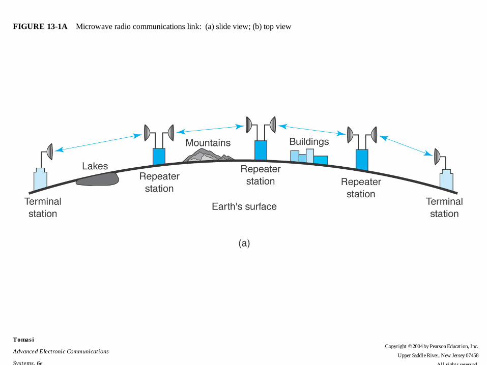
FIGURE 13-1A Microwave radio communications link: (a) slide view; (b) top view
Tomasi
Advanced Electronic Communications
Systems, 6e
Copyright ©2004 by Pearson Educat ion, Inc.
Upper Saddle River, New Jersey 07458
All rights reserved.

FIGURE 13-1B Microwave radio communications link: (a) slide view; (b) top view
Tomasi
Advanced Electronic Communications
Systems, 6e
Copyright ©2004 by Pearson Educat ion, Inc.
Upper Saddle River, New Jersey 07458
All rights reserved.

FIGURE 13-2A Simplified block diagram of a microwave radio: (a) transmitter; (b) receiver
Tomasi
Advanced Electronic Communications
Systems, 6e
Copyright ©2004 by Pearson Educat ion, Inc.
Upper Saddle River, New Jersey 07458
All rights reserved.

FIGURE 13-2B Simplified block diagram of a microwave radio: (a) transmitter; (b) receiver
Tomasi
Advanced Electronic Communications
Systems, 6e
Copyright ©2004 by Pearson Educat ion, Inc.
Upper Saddle River, New Jersey 07458
All rights reserved.
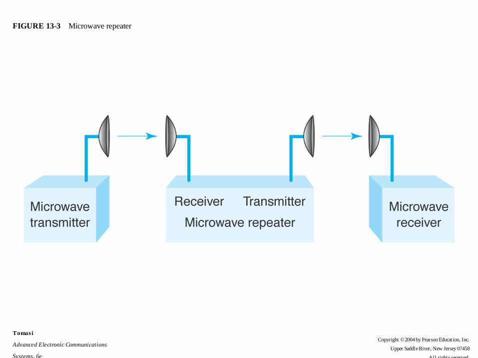
FIGURE 13-3 Microwave repeater
Tomasi
Advanced Electronic Communications
Systems, 6e
Copyright ©2004 by Pearson Educat ion, Inc.
Upper Saddle River, New Jersey 07458
All rights reserved.

FIGURE 13-4A Microwave repeaters: (a) IF; (b) baseband; (c) baseband; (d) RF
Tomasi
Advanced Electronic Communications
Systems, 6e
Copyright ©2004 by Pearson Educat ion, Inc.
Upper Saddle River, New Jersey 07458
All rights reserved.

FIGURE 13-4B Microwave repeaters: (a) IF; (b) baseband; (c) baseband; (d) RF
Tomasi
Advanced Electronic Communications
Systems, 6e
Copyright ©2004 by Pearson Educat ion, Inc.
Upper Saddle River, New Jersey 07458
All rights reserved.

FIGURE 13-4C Microwave repeaters: (a) IF; (b) baseband; (c) baseband; (d) RF
Tomasi
Advanced Electronic Communications
Systems, 6e
Copyright ©2004 by Pearson Educat ion, Inc.
Upper Saddle River, New Jersey 07458
All rights reserved.

FIGURE 13-4D Microwave repeaters: (a) IF; (b) baseband; (c) baseband; (d) RF
Tomasi
Advanced Electronic Communications
Systems, 6e
Copyright ©2004 by Pearson Educat ion, Inc.
Upper Saddle River, New Jersey 07458
All rights reserved.

TABLE 13-2 Reliability and Outage Time
Tomasi
Advanced Electronic Communications
Systems, 6e
Copyright ©2004 by Pearson Educat ion, Inc.
Upper Saddle River, New Jersey 07458
All rights reserved.

FIGURE 13-5 Frequency diversity microwave system
Tomasi
Advanced Electronic Communications
Systems, 6e
Copyright ©2004 by Pearson Educat ion, Inc.
Upper Saddle River, New Jersey 07458
All rights reserved.

FIGURE 13-6A Space diversity: (a) two receive antennas; (b) two transmit antennas
Tomasi
Advanced Electronic Communications
Systems, 6e
Copyright ©2004 by Pearson Educat ion, Inc.
Upper Saddle River, New Jersey 07458
All rights reserved.

FIGURE 13-6B Space diversity: (a) two receive antennas; (b) two transmit antennas
Tomasi
Advanced Electronic Communications
Systems, 6e
Copyright ©2004 by Pearson Educat ion, Inc.
Upper Saddle River, New Jersey 07458
All rights reserved.

FIGURE 13-7A Microwave protection switching arrangements: (a) hot standby; (b) diversity
Tomasi
Advanced Electronic Communications
Systems, 6e
Copyright ©2004 by Pearson Educat ion, Inc.
Upper Saddle River, New Jersey 07458
All rights reserved.

FIGURE 13-7B Microwave protection switching arrangements: (a) hot standby; (b) diversity
Tomasi
Advanced Electronic Communications
Systems, 6e
Copyright ©2004 by Pearson Educat ion, Inc.
Upper Saddle River, New Jersey 07458
All rights reserved.

FIGURE 13-9 Microwave terminal station: (a) transmitter; (b) receiver
Tomasi
Advanced Electronic Communications
Systems, 6e
Copyright ©2004 by Pearson Educat ion, Inc.
Upper Saddle River, New Jersey 07458
All rights reserved.

FIGURE 13-10A Microwave terminal station: (a) transmitter; (b) receiver
Tomasi
Advanced Electronic Communications
Systems, 6e
Copyright ©2004 by Pearson Educat ion, Inc.
Upper Saddle River, New Jersey 07458
All rights reserved.

FIGURE 13-10B Microwave terminal station: (a) transmitter; (b) receiver
Tomasi
Advanced Electronic Communications
Systems, 6e
Copyright ©2004 by Pearson Educat ion, Inc.
Upper Saddle River, New Jersey 07458
All rights reserved.

FIGURE 13-11 Microwave radio IF repeater block diagram
Tomasi
Advanced Electronic Communications
Systems, 6e
Copyright ©2004 by Pearson Educat ion, Inc.
Upper Saddle River, New Jersey 07458
All rights reserved.

FIGURE 13-12A (a) Multihop interference; (b) high/low microwave system
Tomasi
Advanced Electronic Communications
Systems, 6e
Copyright ©2004 by Pearson Educat ion, Inc.
Upper Saddle River, New Jersey 07458
All rights reserved.

FIGURE 13-12B (a) Multihop interference; (b) high/low microwave system
Tomasi
Advanced Electronic Communications
Systems, 6e
Copyright ©2004 by Pearson Educat ion, Inc.
Upper Saddle River, New Jersey 07458
All rights reserved.

FIGURE 13-13A Eight-channel high/low frequency plan: (a) west to east; (b) east to west
Tomasi
Advanced Electronic Communications
Systems, 6e
Copyright ©2004 by Pearson Educat ion, Inc.
Upper Saddle River, New Jersey 07458
All rights reserved.

FIGURE 13-13B Eight-channel high/low frequency plan: (a) west to east; (b) east to west
Tomasi
Advanced Electronic Communications
Systems, 6e
Copyright ©2004 by Pearson Educat ion, Inc.
Upper Saddle River, New Jersey 07458
All rights reserved.

FIGURE 13-14 Microwave propagation paths
Tomasi
Advanced Electronic Communications
Systems, 6e
Copyright ©2004 by Pearson Educat ion, Inc.
Upper Saddle River, New Jersey 07458
All rights reserved.

FIGURE 13-15 Microwave line-of-sight path showing first Fresnel zones
Tomasi
Advanced Electronic Communications
Systems, 6e
Copyright ©2004 by Pearson Educat ion, Inc.
Upper Saddle River, New Jersey 07458
All rights reserved.

FIGURE 13-16 Median duration of fast fading
Tomasi
Advanced Electronic Communications
Systems, 6e
Copyright ©2004 by Pearson Educat ion, Inc.
Upper Saddle River, New Jersey 07458
All rights reserved.

FIGURE 13-17 System gains and losses
Tomasi
Advanced Electronic Communications
Systems, 6e
Copyright ©2004 by Pearson Educat ion, Inc.
Upper Saddle River, New Jersey 07458
All rights reserved.
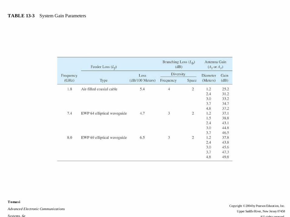
TABLE 13-3 System Gain Parameters
Tomasi
Advanced Electronic Communications
Systems, 6e
Copyright ©2004 by Pearson Educat ion, Inc.
Upper Saddle River, New Jersey 07458
All rights reserved.

FIGURE 13-18 Microwave radio link signal levels relative to system gains and losses
Tomasi
Advanced Electronic Communications
Systems, 6e
Copyright ©2004 by Pearson Educat ion, Inc.
Upper Saddle River, New Jersey 07458
All rights reserved.

FIGURE 13-19 System gain diagram for Example 24-4
Tomasi
Advanced Electronic Communications
Systems, 6e
Copyright ©2004 by Pearson Educat ion, Inc.
Upper Saddle River, New Jersey 07458
All rights reserved.

FIGURE 13-20 System gain diagram for Example 24-5
Tomasi
Advanced Electronic Communications
Systems, 6e
Copyright ©2004 by Pearson Educat ion, Inc.
Upper Saddle River, New Jersey 07458
All rights reserved.