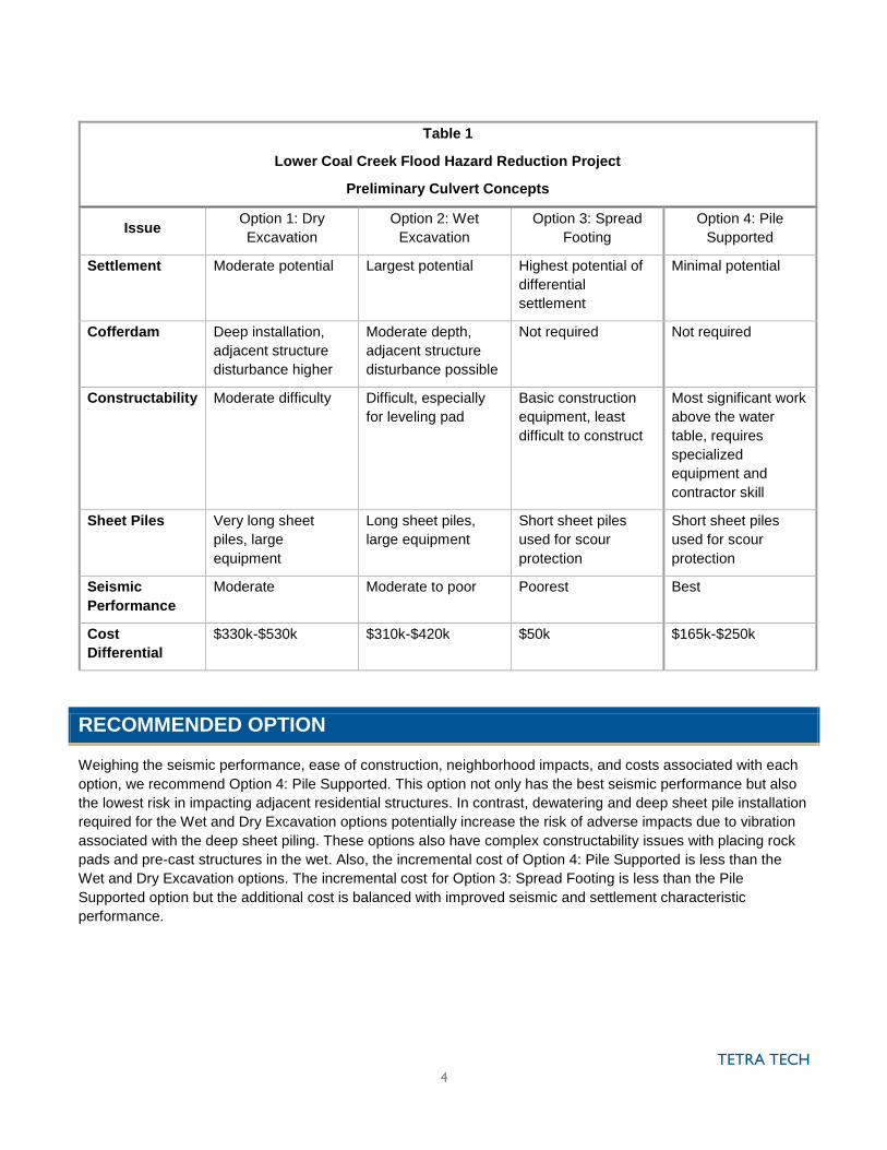
table 1 summarizes the risk and constructability issues
TRANSCRIPT

MEMO
Tetra Tech 1420 5th Avenue, Suite 550, Seattle, WA 98101
Tel 206.728.9655 Fax 206.883.9301 tetratech.com
To: Bruce Jensen/City of Bellevue
Cc: Dave McCormack/Aspect Consulting
From: Jerry Scheller, Greg Gaasland, Theo Prince
Date: December 17, 2015
Revised: October 11, 2016
Subject: Lower Coal Creek Culvert Replacement Alternative Concepts
This memo summarizes different culvert configurations for the lower Coal Creek culvert replacement project
focusing on the different foundations that may be used for the proposed culverts. As discussed at our meeting on
December 10th, the preliminary results of the subsurface investigations revealed very poor soil conditions under
each culvert location. The project area consists of about 5 feet of fill over 25 to 55 feet of very soft and liquefiable
material which is compounded by a high water table that is about 6 feet below existing grade. The poor soil
conditions prompted the evaluation of foundation options beyond the typical spread footing approach that is
commonly used for precast culverts. Geotechnical issues and a geologic cross section are provided in Attachment
A.
OPTION 1: DRY EXCAVATION
Option 1: Dry Excavation consists of a 4-sided precast 2-piece box culvert where the culvert invert is placed 2 feet
below the existing creek thalweg (for scour protection). See Figure 1. A 4-sided box also reduces bearing
pressure to mitigate the settling potential. The culvert would be supported by a 2’ thick gravel bearing fill pad
reinforced with geogrid/fabric. This places the structure invert approximately 5’ below the water table thus
requiring extra effort to control the groundwater. A perimeter cofferdam would be used to isolate the construction
area for the structure excavation for dewatering allowing for dry excavation and the use of conventional
techniques for construction of the bearing fill pad, structure placement and site restoration.
There are several constructability issues to resolve with this approach. The amount of dewatering required for the
Dry Excavation option has the potential to drawdown the groundwater table outside of the cofferdam area
potentially causing adverse settling of the adjacent residential homes. Some structure locations would also
require depressurization or removal of fine-grained materials below the foundations to prevent base heave during
excavation. Also, the deep installation of the sheet piles for the cofferdam would cause vibrations which may
damage (or be perceived as causing damage) to adjacent residential structures. The cost of the dewatering and
cofferdam is also very expensive.
The Dry Excavation option would add about $330,000 to $530,000 to the cost of each structure, depending on
location, primarily due to the need for relatively deep sheet piles, bracing, and well points for dewatering.
The Dry Excavation option is considered to have the highest risk of adverse impacts for all options considered.

TETRA TECH 2
Table 1 summarizes the risk and constructability issues associated with this option.
Advantages
Ease and predictability of construction in the dry
Decreased risk of long-term differential settlement due to geogrid reinforcement to the culvert
Scour protection is managed by 4-sided box culvert
Low bearing pressure may mitigate post-construction settlement.
Disadvantages
Most potential for risk of settlement impacts from deep dewatering including: o surrounding homes o potential for bottom heave o Increased risk of short- and long-term differential settlement
Most potential for vibration from deep sheeting
OPTION 2: WET EXCAVATION
Option 2: Wet Excavation would have a similar configuration as the Dry Excavation option except the cofferdam
sheet piles would not extend the full depth to firm subsoil. See Figure 1. As a result, the bottom of the excavation
would be below the groundwater level and placement of the gravel bearing pad would be in the wet. Constructing
in the wet would be more difficult and require a 3’ thick pad rather than the 2’ pad installed with the Dry
Excavation option. However, the negative impacts associated with the dewatering and deeper sheet pile
installation required for the Dry Excavation option are lessened with this option.
The Wet Excavation option would add about $310,000 to $420,000 to the cost of each structure, depending on
location.
The Wet Excavation option is considered to have the next highest risk of adverse impacts for all options
considered.
Table 1 summarizes the risk and constructability issues associated with this option.
Advantages
Shallow site dewatering required
Lower risk of nearby settlement
Scour protection is provided by 4-sided box
Disadvantages
More susceptible to differential settlement due to lack of geogrid for the bearing pad
Some potential of vibration to adjacent structures from shallower cofferdam sheeting
Difficult to place gravel pad in the wet
OPTION 3: SPREAD FOOTING
Option 3: Spread Footing would include a precast 3-sided structure on a shallow-depth spread footing supported
by a 3’ deep gravel bearing pad below the footings. See Figure 2. The footings would be placed at the
groundwater elevation which would reduce the amount of dewatering required and eliminate the need for a
cofferdam. Because the groundwater elevation is about the same level as the creek thalweg and there is no

TETRA TECH 3
bottom in the structure, relatively shallow sheet piles (about 10’ deep) would be required on the inside of the
spread footing to provide scour protection.
The constructability issue with this approach would primarily be due to the difficulty installing the gravel bearing
pads supporting the spread footings in the wet. However, the depth of excavation would be several feet shallower
than required for the cofferdam in the Wet and Dry Excavation options. Also, this option would have a greater
potential for long-term differential settlement.
The Spread Footing option would add about $50,000 to the cost of each structure.
The Spread Footing option is considered to have the second lowest risk of adverse impacts for all options
considered.
Table 1 summarizes the risk and constructability issues associated with this option.
Advantages
Very limited site dewatering required using conventional dewatering techniques
Lowest risk of settlement at nearby residential structures
Least potential of vibration from sheeting
Smaller equipment required than pile supported option below
Disadvantages
Most susceptible to long-term differential settlement
Minor difficulties of construction in the wet
Minor sheeting is required for scour protection
OPTION 4: PILE SUPPORTED
Option 4: Pile Supported includes a precast 3-sided culvert similar to the Spread Footing option but is supported
by piles in place of the spread footing. See Figure 3. The piles used for this option would be helical piles with an
18” diameter head which are “screwed”, rather than driven, when installed. Helical piles mitigate the potential for
damage to adjacent structures from vibration associated with more conventional driven piles. Constructability
issues are similar to the Spread Footing option except that there would be less excavation in the wet due to the
elimination of the bearing fill pad below the spread footing. There would however be more expenses associated
with the helical piles and the pile cap needed to support the precast box structure. Also, because the precast box
structure is supported by the denser deep soils, there is potential that differential settlement would occur because
the surrounding areas may experience greater settlement than the structure.
The Pile Supported option would add about $165,000 to $250,000 to the cost of each structure depending on
location.
The Pile Supported option is considered to have the lowest risk of adverse impacts for all options considered.
Table 1 summarizes the risk and constructability issues associated with this option.
Advantages
Least site dewatering required
Lowest risk of nearby settlement from dewatering
Least potential of vibration from sheeting
Disadvantages
Susceptible to long-term differential settlement (less than surrounding area)
Shallow depth sheeting may be needed for scour protection
TETRA TECH 4
Table 1
Lower Coal Creek Flood Hazard Reduction Project
Preliminary Culvert Concepts
Issue Option 1: Dry
Excavation
Option 2: Wet
Excavation
Option 3: Spread
Footing
Option 4: Pile
Supported
Settlement Moderate potential Largest potential Highest potential of
differential
settlement
Minimal potential
Cofferdam Deep installation,
adjacent structure
disturbance higher
Moderate depth,
adjacent structure
disturbance possible
Not required Not required
Constructability Moderate difficulty Difficult, especially
for leveling pad
Basic construction
equipment, least
difficult to construct
Most significant work
above the water
table, requires
specialized
equipment and
contractor skill
Sheet Piles Very long sheet
piles, large
equipment
Long sheet piles,
large equipment
Short sheet piles
used for scour
protection
Short sheet piles
used for scour
protection
Seismic
Performance
Moderate Moderate to poor Poorest Best
Cost
Differential
$330k-$530k $310k-$420k $50k $165k-$250k
RECOMMENDED OPTION
Weighing the seismic performance, ease of construction, neighborhood impacts, and costs associated with each
option, we recommend Option 4: Pile Supported. This option not only has the best seismic performance but also
the lowest risk in impacting adjacent residential structures. In contrast, dewatering and deep sheet pile installation
required for the Wet and Dry Excavation options potentially increase the risk of adverse impacts due to vibration
associated with the deep sheet piling. These options also have complex constructability issues with placing rock
pads and pre-cast structures in the wet. Also, the incremental cost of Option 4: Pile Supported is less than the
Wet and Dry Excavation options. The incremental cost for Option 3: Spread Footing is less than the Pile
Supported option but the additional cost is balanced with improved seismic and settlement characteristic
performance.


TETRA TECH 5
ATTACHMENT A – GEOTECHNICAL SUMMARY


DRAFT MEMORANDUM
Project No.: 140362
December 21, 2015
To: Jerry Scheller, PE Tetra Tech
cc: Greg Gaasland, PE – Tetra Tech Henry Haselton, PE – Aspect Consulting
From: David H. McCormack, LEG Senior Associate Engineering Geologist [email protected] Nicholas C. Szot, PE Project Geotechnical Engineer [email protected]
Re: Lower Coal Creek Flood Hazards Reduction – Preliminary Geotechnical Findings
This memorandum presents a preliminary summary of early geotechnical findings of subsurface conditions, anticipated soil behavior, and geotechnical considerations for design of culvert foundations. These results, analyses, and recommendations are preliminary and subject to additional analysis. We understand that these early findings will be used by Tetra Tech and the City of Bellevue to support a decision on the basic foundation type – likely either pile-supported, or shallow foundations such as spread footings or mat foundations. Attachments (all works in progress) are included that show the overall site layout, a preliminary draft subsurface profile, and a table that summarizes considerations for pile-supported and shallow foundation options. Subsurface Conditions
Aspect Consulting completed the five borings and groundwater piezometer installations at the culvert replacement locations. The profiles attached to this email show the boring locations, depths, Standard Penetration Test blow count “N”-values, and geologic units.
Subsurface conditions encountered consist of a thin layer of sandy fill, overlying very soft, weak, and compressible floodplain and lake deposits consisting of silt, clay, peat, and loose sand layers. The very soft and loose soil was up to 55 feet deep and underlain by dense sand

DRAFT MEMORANDUM December 21, 2015 Project No.: 140362
Page 2
and gravel. The dense sand and gravel was encountered at a depth of about 55 feet nearest Lake Washington at Skagit Key and shallowed to about 25 moving inland at Cascade Key. Groundwater levels are at about 6 feet below street grade.
Soil Behavior
Silty and clayey soils are very weak to depths ranging from near the ground surface to about 25 to 55 feet below ground surface.
Organic-rich soils are compressible and subject to consolidation/settlement when dewatered or loaded.
Soils are vibration sensitive.
Loose sandy soils below the water table are liquefiable.
Design Criteria and Considerations
Stream crossing widths of about 24 feet are planned, with scour depths of about 4 feet.
We are assuming the structures will be designed to American Association of State Highway and Transportation Officials (AASHTO) LRFD Bridge Design Specifications.
Aspect has not been provided with long-term static and seismic performance criteria that would be considered acceptable. For the long-term static condition, we have assumed that some periodic maintenance (such as repaving to mitigate minor differential settlement) to the bridge approaches will be acceptable. For a design-level earthquake we have assumed that it will be necessary for the culverts to remain structurally intact and sufficiently accessible for emergency vehicle access, although some damage to the approach ramp and surrounding areas may occur and can be tolerated.
Options being considered for support of the culverts include:
1. Mat foundation constructed over granular fill pad with foundation construction in the dry;
2. Mat foundation constructed over granular fill with foundation constructed in the wet;
3. Deep foundations (piles) extending to bearing soils; and,
4. Spread footings constructed over granular fill pad constructed above thalweg level and above the water table, with scour protection provided by short sheet piles.
Advantages and disadvantages of each option are presented in the attached table.
We anticipate the soft material will compress under new shallow foundation loads resulting in settlements occurring over the first six months post construction. The magnitude of settlement is anticipated to be on the order of 3 to 12 inches and largely dependent on the new load exerted. In addition to settlement caused by new loads, we anticipate that the peat and organic-rich soils present throughout the greater site area will experience long-term settlement that will continue over many years.

DRAFT MEMORANDUM December 21, 2015 Project No.: 140362
Page 3
The loose sandy soils below the groundwater level (about 6 feet) are susceptible to liquefaction from the design seismic event. This will result in liquefaction settlement, probably on the order of 6 to 12 inches below shallow foundation elevations.
For foundations placed at or below the thalweg, dewatering will be required to reach the culvert construction depth and complete in-the-dry construction, and for stabilization of the soils at the base of the excavation. Dewatering may require use of deep sheet piles to create a water-tight cofferdam.
Soils in the vicinity of the site are anticipated to be sensitive to vibrations from driving sheets or other piles. Organic-rich soils in the site area are expected to be highly susceptible to settlement when dewatered.
Protection from settlement or mitigation of settlement during dewatering would be required and may be part of the shoring selection process.
As an alternative to shallow foundations, piles embedded into the dense sand and gravel beneath the soft compressible and liquefiable soils could be used to support the culverts. The piles would experience drag loading from the organic-rich and liquefiable soil profile settling downward against the pile surface over the long term, but can be designed to account for this. Pile driving vibrations and damage to sensitive soils and buildings could be mitigated by use of helical piles that are screwed into the ground, not impact or vibratory driven.
All options (shallow foundations and pile-supported) will be subjected to large lateral loads as a result of liquefaction-initiated ‘flow failure’ during the design-level earthquake. The culvert structure or piles may not be capable of withstanding the large lateral loads and will need to be further investigated during design.
Without extensive ground improvement, any of the shallow foundations or pile-supported design alternatives may not be capable of providing the level of service after the design-level earthquake that is specified by the AASHTO LRFD Bridge Design Specification.
Conclusions
In our opinion, the pile-supported option would provide the best long-term performance, reduction of seismic performance concerns, and eliminates risks of damage to adjacent structures that might be introduced by dewatering and the need for deep driven sheet piles.
Limitations
The information provided in this memorandum is preliminary. Additional evaluations and analyses will be required as the design evolves. Work for this project was performed for the Tetra Tech (Client) and the City of Bellevue, and this memorandum was prepared in accordance with generally accepted professional practices for the nature and conditions of work completed in the same or

DRAFT MEMORANDUM December 21, 2015 Project No.: 140362
Page 4
similar localities, at the time the work was performed. This memorandum does not represent a legal opinion. No other warranty, expressed or implied, is made.
All reports prepared by Aspect Consulting for the Client apply only to the services described in the Agreement(s) with the Client. Any use or reuse by any party other than the Client is at the sole risk of that party, and without liability to Aspect Consulting. Aspect Consulting’s original files/reports shall govern in the event of any dispute regarding the content of electronic documents furnished to others.
Attachments: Site and Exploration Plan
Geologic Cross Section (three figures)
LCC Options Analysis Table
S:\City of Bellevue\Lwr Coal Ck Flood Reduct\Deliverables\LCC Preliminary Geotech Findings Memo 12-21-15.docx

]
]
T
T
T
T
T
"/
"/"/
"/
"/
"/"/
"/
"/"/
"/
&<
&<
&<
&<
&<
L a k eW
a s h i ng
t on
A
A '
Lower Coal Creek
B-1 (Aspect)
B-2 (Aspect)
B-3 (Aspect)
B-4 (Aspect)
B-5 (Aspect)
B-1 (GeoEngineers)
B-1 (ESNW)B-2 (ESNW)
B-1 & B-2 (Lorilla)
B-1 (ZZA)
BH-2(PanGeo)
BH-1 (PanGeo)
B-2 (Terra)
B-4 (Terra)B-5 (Terra)
B-1 (RZA)
1 16T
H
AVE S E
120 T
HA V
ES EN E W P O R T K Y
D E C A T URKY
S UC I
A KY
S E 4 3 R D S T
VASH
ON K
Y
S E 4 5 T H P L
G L A C I E R K Y
S E 3 7 T H P L
C H E L AN K Y
S E 4 2 N D C T
S E 4 0 T H L N
S E 4 2 N D S T
SE 4 6 T H ST
SE 4 5 T H P L
L AKE H
E I G H TS S T
S E 4 1 S T S T
C A S C A D E K Y
LAKE
WASH
I NG T
O NB L
VDS E
T U L A L I P K Y
I - 4 0 5
I - 4 0 5
L U M M I K Y
I - 4 0 5
I - 4 0 5
I - 40 5
S E 4 0 T H S T
C A S C A D E K Y
LOPE Z K Y
LA K EW A S H I N G T O N
B LV DS E
1 1 9 T H A V E S E
119T
H A V
E S E
C O L U M B I A K Y
L A KE W A S H ING TONBLVD
S E
C R E S C E N T K Y
120'
80'30'
20'10'0' 230'
220'
210'
190'180'
170'160'
210'
200'
190'
180'
180'170'
160'150'
140'130'
190'180'
170'
0'
-10'
210'200'
100'90'30'
20'
150'130'
110'
100'
70'
60'
50'
40'
120'
120'
90'
100'
110'
200'
10'
80'70'
60'
210'
170'
170'
160'
80'
40'
40'
30'30'
30'
20'
30'
20'
20'
-10'-20'
170'
30'
20'
Lower Skagit Key
Newport Key
Glacier Key
Upper Skagit Key
Cascade Key
GIS Path: T:\projects_8\LowerCoalCreek_140362\Delivered\02_SiteMap.mxd || Coordinate System: NAD 1983 StatePlane Washington North FIPS 4601 Feet || Date Saved: 10/19/2015 || User: ecrumbaker || Print Date: 10/19/2015
0 500 1,000
Feet
T CulvertReplacement
&<Soil Boring byAspect Consulting
"/Soil Boring by Others(Company Name)
]
]SubsurfaceCross Section10-ft LiDAR Contour5-ft LiDAR ContourParcelsBuilding
C O N SU LTI N G
FIGURE NO.
2OCT-2015PROJECT NO.140362
BY:EAC / NCSREVISED BY:
- - -
Site and Exploration MapLower Coal Creek Flood Hazard Reduction
Bellevue, Washington


20
30
10
0
Elev
atio
n in
Fee
t
Qgo
Fill
0 100 200 300 400 500 600 700 800 900 1,000 1,100
Distance in Feet
-10
1
-20
-30
-40
-50
-60
B-2 (ESNW)(OFFSET 234' NE) B-1 (ESNW)
(OFFSET 183' NE)
B-1(GEOENGINEERS)
(OFFSET 299' SW)
B-1(ASPECT)
B-1(LORILLA)(OFFSET 69' NE) B-2 (ASPECT)
B-2(LORILLA)(OFFSET 69' NE)
10
3
3
1
2
2
2
2
2
2
8
5
28
11
6
2
3
2
2
2
2
2
2
2
2
2
16
6
4
0
1
0
1
0
2
0
14
6
5
56
32
62
66
7
3
2
1
3
1
2
5
1
24
19
22
15
200
144
200
7
1
2
5
3
3
5
2
0
39
17
32
32
67
150
SM
ML
SM
OL
PT
CH
MH
SP
PT
SM
SM
ML
SM
OL
PT
CH
MH
CH
SM
SM
OL SP
SP
OL
SM/ML
SM/CL-ML
SM
SP-SM
SP
SP
OL
OL/ML
SM/ML
SM/ML
SP-SM
OL
OL
OL/PT
PT
SM/ML
SP-SM
ML
OL
SP
SM/ML
GP
SP-SM
GW
SW
ML
SP-SM
SP
3
0
0
2
2
2
0
0
0
2
3
3
22
40
62
1
0
0
0
1
1
0
0
29
18
14
0
50
50
SM
SW
ML/OL
ML/PT
PT
CL/ML
SM/ML
SM
SP
SM
ML
ML/SM
OL/PT
SM/CL
SM/ML
CL
SM
GM
Alluvial
Wetland
Lacustrine
Channel
Lacustrine
Lacustrine
Qvr
Lacustrine
Wetland
Wetland
Alluvial
Channel
Channel
Qvr
CAD
Pat
h: Q
:\Lo
wer
Coa
l Cre
ek\1
40
36
2 L
CC
Flo
od H
azar
d R
educ
tion\
20
15
-10
Cro
ss S
ectio
n\14
0362
-AA.
dwg
Sect
ion
A-A'
0-1
200
||
Coo
rdin
ate
Syst
em: N
AD 1
98
3 S
tate
Pla
ne W
ashi
ngto
n N
orth
FIP
S 46
01 F
eet
||
Dat
e Sa
ved:
Dec
08
, 20
15
9:5
7am
|
| U
ser:
scud
d
Horizontal Scale: 1" = 100'Vertical Scale: 1" = 10'Vertical Exaggeration 10x
Geologic Cross Section A-A'Lower Coal Creek Flood Hazard Reduction
Bellevue, Washington
OCT-2015PROJECT NO.
140362
FIGURE NO.
2
BY:
NCS/SCCREVISED BY:
-
Feet0 100 200
ANorthwest
A' →Southeast
Mat
ch L
ine
with
Fig
ure
3

1,300 1,400 1,500 1,600 1,700 1,800 1,900 2,000 2,100 2,200 2,300 2
B-3 (ASPECT)
BH-1(PANGEO)(OFFSET 9' SW) BH-2
(PANGEO)(OFFSET 61' NE)
Distance in Feet
140
6
5
4
2
14
38
28
6
4
5
2
2
6
20
SM-ML SM
SP
MH
OL
PT
ML/SP
SP
SW-SP
SM-ML
SP-SM
GP-SP
1
13
1
2
2
3
10
2
25
2
7
50
36
SM
SM
ML
SW-SM
OL/PT
ML
SM/ML
ML
SW-SM
MH
SW-SM
MH
SM
Lacustrine
Wetland
Wetland
Alluvial
Qvr
Qvr
Qvr
CAD
Pat
h: Q
:\Lo
wer
Coa
l Cre
ek\1
40
36
2 L
CC
Flo
od H
azar
d R
educ
tion\
20
15
-10
Cro
ss S
ectio
n\14
0362
-AA.
dwg
Sect
ion
A-A'
120
0-24
00
||
Coo
rdin
ate
Syst
em: N
AD 1
98
3 S
tate
Pla
ne W
ashi
ngto
n N
orth
FIP
S 46
01 F
eet
||
Dat
e Sa
ved:
Dec
08
, 20
15
9:5
7am
|
| U
ser:
scud
d
Horizontal Scale: 1" = 100'Vertical Scale: 1" = 10'Vertical Exaggeration 10x
Geologic Cross Section A-A'Lower Coal Creek Flood Hazard Reduction
Bellevue, Washington
OCT-2015PROJECT NO.
140362
FIGURE NO.
3
BY:
NCS/SCCREVISED BY:
-
Feet0 100 200
←ANorthwest
A' →Southeast
20
30
10
0
Elev
atio
n in
Fee
t
-10
-20
-30
-40
40
Mat
ch L
ine
with
Fig
ure
4
Mat
ch L
ine
with
Fig
ure
2

2,500 2,600 2,700 2,800 2,900 3,000 3,100 3,200 3,300 3,400
Distance in Feet
B-4 (TERRA)(OFFSET 7' SW)
B5 (TERRA)(OFFSET 18' NE)
B-1 (RZA)(OFFSET 12' SW)
B-4 (ASPECT)
B-5 (ASPECT)
2
0.5
0.5
4
8
133
100
1
1
0
20
200
19
42
91
18
8
116
120
133
150
SP/SM
SM
SP
SM
SM
MH
?
ML
SW
CL-ML
CL-ML
SP/GP
SP
ML
SP-SM
CL-MLSM
CL-ML
SP/GP
1
0
1
1
1
28
50
50
50
0
0
0
22
24
54
SM
P/ML
L/MH
L/SM
OL/PT
M/ML
SM
GM
SM
SW
CL
SM/ML
ML
SM
Lacustrine
Lacustrine
Alluvial
Qvr
Qvr
Qva
Qvt
CAD
Pat
h: Q
:\Lo
wer
Coa
l Cre
ek\1
40
36
2 L
CC
Flo
od H
azar
d R
educ
tion\
20
15
-10
Cro
ss S
ectio
n\14
0362
-AA.
dwg
Sect
ion
A-A'
240
0-33
00
||
Coo
rdin
ate
Syst
em: N
AD 1
98
3 S
tate
Pla
ne W
ashi
ngto
n N
orth
FIP
S 46
01 F
eet
||
Dat
e Sa
ved:
Dec
08
, 20
15
9:5
6am
|
| U
ser:
scud
d
Horizontal Scale: 1" = 100'Vertical Scale: 1" = 10'Vertical Exaggeration 10x
Geologic Cross Section A-A'Lower Coal Creek Flood Hazard Reduction
Bellevue, Washington
OCT-2015PROJECT NO.
140362
FIGURE NO.
4
BY:
NCS/SCCREVISED BY:
-
Feet0 100 200
←ANorthwest
A'Southeast
-10
0
10
20
30
40
50
60
70
Elev
atio
n in
Fee
t80
Mat
ch L
ine
with
Fig
ure
3

Lower Coal Creek Options Analysis
Option General Description Advantage Disadvantage
Option 1: Deep 4-Sided Box Grade Supported Wet Excavation
4-sided precast concrete box; U-section with Lid
Stream diversion
Driven sheet pile temporary shoring along span
Excavation in the wet
3-foot-thick Crushed Rock/Spalls Bearing Fill Pad (no-geogrid/fabric) excavated and placed in the wet.
No long-term dewatering
Place Culvert U-section in wet.
Place streambed materials in U-section
Place box lid and cover.
Excavate siphons and carrier pipe using open-trench (or trenchless?) methods.
No dewatering
Shallower Sheet Pile Depths and less robust bracing.
Dewatering settlement of nearby area not a concern.
Constructability challenges working in the wet.
Working in wet precludes placement of separator fabric at excavation base and geogrid reinforcement within bearing fill pad.
More susceptible to differential settlement due to lack of geogrid reinforcement in fill pad.
Subject to settlement immediately after construction, long-term, and from liquefaction. Culvert may settle more than the surrounding roadway.
Grading of fill pad underwater, more difficult to level.
Option 2: Deep 4-Sided Box Grade Supported Dry Excavation
4-sided precast concrete box;
Stream diversion
Driven sheet pile temporary shoring along span and ends (sheet pile cofferdam)
Dewatering 12 feet (2 feet below excavation base)
2-foot-thick Crushed Rock/Spalls Bearing Fill Pad reinforced with geogrid/fabric excavated and placed in the dry.
Place Culvert box and streambed materials in the dry.
Excavate siphons and carrier pipe using open-trench (or trenchless?) methods.
Construction in the dry allows a separator fabric and geogrid reinforcement to be placed in the fill pad resulting better differential settlement performance for static and liquefaction scenarios.
Deeper sheet piles and robust bracing temporary shoring needed for dewatering. Very deep sheet piles (55 feet) at Lower Skagit and Newport Key locations.
Requires about 12 feet of active dewatering. Dewatering drawdown could reach outside the sheet pile cofferdam and cause settlement of surrounding area. City is sensitive to this.
Depressurization below excavation base, or removal of additional 5-7 feet of fine-grained material at excavation base (in the wet) needed to prevent base heave during excavation at Upper Skagit and Cascade Keys.
Subject to settlement immediately after construction, long-term, and from liquefaction. Culvert may settle more than the surrounding roadway.
Option 3: Pile Supported Bridge
Stream diversion.
Install piles to dense soil (25 to 60 feet below grade) to support voided slab
Some excavation in the wet for stream channel grading and scour protection.
Excavate siphons and carrier pipe using open-trench (or trenchless?) methods.
Piles will limit settlement of the bridge in static and liquefied scenarios.
Smaller excavation and trench boxes for pile cap construction.
Significant active dewatering not required.
Many pile options to consider – driven, drilled, helical/screw.
Driving vibrations (driven piles only) could damage nearby residences. Noise complaints.
Bridge will not settle long-term with surrounding area, may create a lip at roadway interface. Articulated approach slab or geogrid at interface could help mitigate, but some repaving likely needed in future.

Option 4:
Shallow 3-Sided Grade Supported Wet Excavation
Stream diversion.
3-sided precast concrete culvert supported onshallow footings located just above groundwaterelevation.
3-foot-thick Crushed Rock/Spalls Bearing Fill Pad(no-geogrid/fabric) excavated and placed in thewet beneath the footings.
No long-term dewatering
Shallow sheet piles around footings to preventscour.
Excavate siphons and carrier pipe using open-trench methods.
No significant dewatering or deep excavationbelow groundwater.
Dewatering settlement of nearby area not aconcern.
Sheet piles for scour protection eliminateneed for deep excavation.
Trenches boxes may be needed, but notrobust/expensive shoring such as bracedsheet piles.
Working in wet precludes placement of separator fabricand geogrid reinforcement within bearing fill pad beneaththe footings.
More susceptible to differential settlement than 4-sidedbox culvert option because of distance and possiblevariability in local subsurface conditions between thediscrete footings.
More susceptible to differential settlement due to lack ofgeogrid reinforcement in fill pad beneath footings.
Subject to settlement immediately after construction,long-term, and from liquefaction. Culvert may settle morethan the surrounding roadway.
Grading of crushed rock/spalls underwater, more difficultto level.
SEISMIC:
Options supported by shallow foundations will undergo vertical settlements on the order of 6 to 12 inches due to liquefaction settlement and will damage the structure.
Options supported by pile foundations will need to be designed to account for drag loading along the piles during liquefaction settlement.
All options (shallow foundations and pile supported) will be subjected to large lateral loads as a result of ‘flow failure’ during the design level earthquake. The structure or piles may not be capable ofwithstanding the large lateral loads.
See flow failure schematic below.