t20 series features - synventive molding solutions t20 series heater options 80 single heater 145...
TRANSCRIPT

T20 Hot Runner Nozzles arefor medium to large partapplications and are avail-able with band or helicalheaters. In most cases oneband heater is required foroperation but an installedspare may be provided ifspace allows. They areavailable in lengths from 160to 500 (“J” dimension).Because the nozzles arethreaded directly into themanifold preload in the coldcondition is not required.
Suitable for all materials andavailable with ten SynventiveControlled Vestige (CV) tipoptions including valve gatesfor zero gate vestige applica-tions.
T20-1
T20 SeriesFeatures
J
Ø10-20
Threaded Tips
Thermocouple
Heat Pipes
ReplaceableHeaters
:serutaeF
mumixamlennahcwolfmumixammm02
)noisnemid"J"(htpeddlom005-061
elpuocomrehtdnaretaehefilgnolelbaecalpeR
sretaehV042
selytspitegitsevdellortnoc01
spitdedaerhtelbaecalpeR
ytimrofinuerutarepmetrofsepiptaehlanretnI
srellifhtiwesohtgnidulcniscitsalpllaroF
aidpit23
All Dimensions in mm

T20-2
T20 SeriesHeater Options
80 single heater145 spare heater installed
J
Ø85
Ø50
120
18
Ø10-20In most cases one heater re-quired for operation. If moldthickness allows a spare bandheater will be installed.When using CV11CM and CV21CMtip styles the 85 diameter heaterclearance hole depth increaseseliminating the 50mm diameterclearance hole. See T20-15 andT20-25.
When the distance from themanifold center locator to the hotrunner nozzle center line exceeds500 the 50 diameter clearancehole must be increased to 55 andthe 85 diameter hole to 90.
J Minimum = 160J Maximum = 380
J From 160-425, K=0
J
Ø65
120
J From 425-500, K=J/2
Ø70
Ø10-20
18
K
Band Heater
Helical HeaterWhen J is greater than 425 twoheaters are required for opera-tion.
When the distance from themanifold center locator to the hotrunner nozzle center line exceeds500 the 65 diameter clearancehole must be increased to 70.
J Minimum = 160J Maximum = 500

T20-3
T20 SeriesOverview
Thermal GateNozzle
See page T20-5 toselect a tip that suitsyour application
CV10- Filled and unfilled materials- Open flow channel/higher flow- 2.0 to 6.0 orifice diameter- Patented seal- Easier mold geometryDimensional data on Pages T20-10, 11 & 12
CV11- Filled and unfilled materials- Cone point delivers more heat to gate- 2.0 to 4.0 orifice diameter- Patented seal- Reduced vestige- Easier mold geometryDimensional data on Pages T20-13, 14 & 15
CV20- Filled and unfilled materials- Open flow channel/higher flow- 2.0 to 6.0 orifice diameter- Patented seal- No witness mark- Easier color changeDimensional data on Pages T20-19, 20 & 21
CV11CM- Filled and unfilled materials- Developed for PA and PBT- 4.0 orifice diameter- Reduced vestige- Easier mold geometryDimensional data on Pages T20-16, 17 & 18
CV21- Filled and unfilled materials- Cone point delivers more heat to gate- 2.0 to 4.0 orifice diameter- Patented seal- Reduced vestige- No witness markDimensional data on Pages T20-22, 23 & 24
CV21CM- Filled and unfilled materials- Developed for PA and PBT- 4.0 orifice diameter- Patented seal- Reduced vestige- No witness markDimensional data on Pages T20-25, 26 & 27

T20-4
T20 SeriesOverview
Valve GateNozzle
See page T20-6 toselect a tip that suitsyour application
VG12- Filled and unfilled materials- “0” vestige- Tapered shut off- 3.9 orifice diameter- Patented seal- Easier mold geometryDimensional data on Pages T20-28 & 29
VG12S- Filled and unfilled materials- “0” vestige- Diametric shut off- Materials having glass fibers- 5.0 orifice diameter- Patented seal- Easier mold geometryDimensional data on Pages T20-30 & 31
VG23S- Filled and unfilled materials- “0” vestige- Diametric shut off- Materials having glass fibers- 5.0 orifice diameter- Patented seal- No witness markDimensional data on Pages T20-34 & 35
VG23- Filled and unfilled materials- “0” vestige- Tapered shut off- 3.9 orifice diameter- Patented seal- No witness markDimensional data on Pages T20-32 & 33

T20-5
T20 SeriesMaterial Compatibility
PE PP PEEK
PPS
PET
PBT
PPO
/PA
PA PPA
POM
PMM
A
ABS
ASA
SAN
PS PC/A
BS
PC PES
PSU
PEI
PPO
TPE
Add
itiv
es
Semi-crystalline Amorphous
A
B
C
D
Material
Tip Style
+ + - - - - - - - - + + + + + + + - - - + -
-++ ----- --+--- --++- -+-
-++ ++-+- --+-+- --++- -+-
-++ ----- --+--- --++- -+-
A
B
C
D
+ + - - - - - - - + - - - + ++ + + + + + +
------00 -++--++-+- - - + +
--00 - - - - -- + + + -- + + - +-- +
------++ -++++++++- - - + +
A
B
C
D
- - - - + + + + - - - -- - -- ---- - -
+++- - +-- - - - -- --- -- --- -
+++- - +-- - - - -- --- -- --- -
+++- - +-- - - - -- --- -- --- -
A
B
C
D
+ + - - - - - - - 0 - - - + -+ + + + + + +
------++ 0 +++-+++ -- -+--
--+---++ 0 +++--+- -- -+--
+-+ + ++ + + --- +0 - -+ + + - - + -
A
B
C
D
+ + - - - - - - - + - - - + +0 + + + + + +
------++ 0 00++-0 -+- ++--
--+ + - - - - -0- + 0 00 -+ + - - + +
--++ ---- 0+- 0 - +- -0 0 +-- +
A
B
C
D
- - - - + + + + - - - -- - -- ---- - -
+++- - +-- - - - -- --- -- --- -
+++- - +-- - - - -- --- -- --- -
+++- - +-- - - - -- --- -- --- -
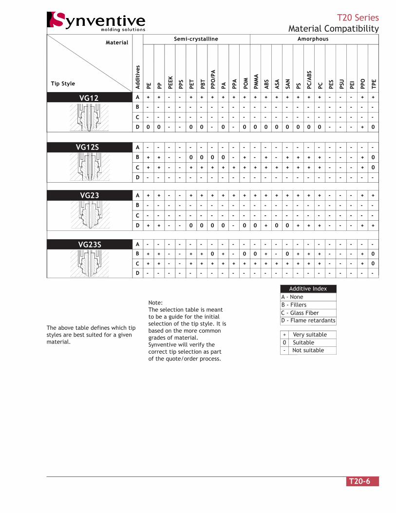
The above table defines which tipstyles are best suited for a givenmaterial.
Note:The selection table is meantto be a guide for the initialselection of the tip style. It isbased on the more commongrades of material.Synventive will verify thecorrect tip selection as partof the quote/order process.
Additive IndexA - NoneB - FillersC - Glass FiberD - Flame retardants
+ Very suitable0 Suitable- Not suitable
CV10
CV11
CV20
CV21
CV11CM
CV21CM
T20-6
T20 SeriesMaterial Compatibility
PE PP PEEK
PPS
PET
PBT
PPO
/PA
PA PPA
POM
PMM
A
ABS
ASA
SAN
PS PC/A
BS
PC PES
PSU
PEI
PPO
TPE
Add
itiv
es
Semi-crystalline Amorphous
A
B
C
D
Material
Tip Style
+ + - - + + + + + + + + - - - + +
- ----- ----- --- --
-00 0-00- 00- --00 0+-
+++ ++
- - - -- -
---- - - - - - - -- - -- - - - -- - -
00 00
A
B
C
D
-++ 0000- -+- --++ 0+--+ ++
+-++ + ++- + + +++ -++++ +-- 0
---- - - - - - - -- - -- - - - -- - -
--- - ---- -- --- ---- - -- - -
A
B
C
D
+ + - - + + + + + + + + - - - + +
- ----- ----- --- --
-++ 0000- 00- --++ ++-
+++ ++
- - - -- -
---- - - - - - - -- - -- - - - -- - -
0+ +0
A
B
C
D
-++ +0++- 00- --++ 0+--+ +0
+-++ + ++- + + +++ -++++ +-- 0
---- - - - - - - -- - -- - - - -- - -
--- - ---- -- --- ---- - -- - -
The above table defines which tipstyles are best suited for a givenmaterial.
Note:The selection table is meantto be a guide for the initialselection of the tip style. It isbased on the more commongrades of material.Synventive will verify thecorrect tip selection as partof the quote/order process.
Additive IndexA - NoneB - FillersC - Glass FiberD - Flame retardants
+ Very suitable0 Suitable- Not suitable
VG12
VG12S
VG23S
VG23

T20-7
T20 SeriesFlow Rate
Maximum flow rate of hot runnernozzles varies depending on themelt index of the material beingprocessed.
The flow rate of any hot runnernozzle is controlled by threefactors:
1) Flow bore size
2) Melt temperature, viscosity vs shear rate relationship.
3) The cavity wall thickness, flow length from the gate, mold temperature and required fill rate.
The last two factors can combineto change the maximum shotcapacity by a factor of 5 or more.Synventive uses computerizedflow analysis to assure thecorrect nozzle is chosen.
Example
Material: PE
Tip style: CV10
Maximum flow rate: 1000 grams/second
Note:Values in the table do notinclude reinforced materialsor materials with fillers.
lairetaMelytSpiT
02VC/01VC )SN(12VC/)SN(11VC )S(32GV/)S(21GV
SBA ces/mg006 ces/mg006 ces/mg054
CP ces/mg004 ces/mg004 ces/mg001
OPP ces/mg006 ces/mg006 ces/mg001
TBP ces/mg006 ces/mg006 ces/mg001
CP/TBP ces/mg573 ces/mg573 ces/mg001
SBA/CP ces/mg004 ces/mg004 ces/mg001
SP ces/mg0001 ces/mg0001 ces/mg005
PP ces/mg0051 ces/mg0051 ces/mg005
AP ces/mg009 ces/mg009 ces/mg573
MOP ces/mg523 ces/mg523 ces/mg002
EP ces/mg0001 ces/mg0001 ces/mg005
cilyrcA ces/mg006 ces/mg006 ces/mg052
CVP ces/mg523 ces/mg523 ces/mg002
RPT - ces/mg009 ces/mg005

T20-8
T20 SeriesOrifice Guidelines
This table lists the normal gateorifice required to fill an averagecavity of the listed wall thicknessand surface area.
The orifice diameter is based onthe flow and freeze characteris-tics of each type of plastic at itsnormal processing conditions. It isnot dependent on whether thecavity is fed by a hot or coldrunner.
Some of the listed wall thicknessand surface area combinations arenot applicable to all plasticsbecause of the flow length to wallratios of each material. Consultplastic supplier’s processingrecommendations.
Due to the gate limitations of eachhot runner nozzle, the actual gatemay be slightly smaller or largerthan the tabulated orifice.
Material FactorsUse tabulated orifice for PE, PP, PS,SAN and PUR.
Use tabulated orifice x 1.15 for POM,PC, PPO and ABS.
Use tabulated orifice x 1.30 for Acrylic,PA, PET, and PBT
Use tabulated orifice x 1.50 for PVC.
For non-reinforced PA, PET and PBT theminimum orifice diameter should be4.0. For reinforced PA, PET and PBTthe minimum orifice diameter shouldbe 4.0.
Part Area is total outside area and notthe projected area of the part.
)hcni(mmenilediuGretemaiDecifirOaerAtraP )hcni(/mmssenkcihtllaW
mmqs hcniqs57.0)30.0(
00.1)40.0(
52.1)50.0(
05.1)60.0(
57.1)70.0(
00.2)80.0(
52.2)90.0(
05.2)01.0(
00.3)31.0(
00.4)61.0(
006 09.0 09.0 09.0 09.0 09.0 09.0 59.0 00.1 21.1 72.1
0.1 530.0 530.0 530.0 530.0 530.0 530.0 730.0 930.0 440.0 050.0
0021 09.0 09.0 09.0 29.0 00.1 50.1 21.1 71.1 23.1 05.1
0.2 530.0 530.0 530.0 630.0 930.0 140.0 440.0 640.0 250.0 950.0
0081 09.0 09.0 59.0 20.1 01.1 71.1 52.1 03.1 74.1 86.1
0.3 530.0 530.0 730.0 040.0 340.0 640.0 940.0 150.0 850.0 660.0
0042 09.0 09.0 20.1 01.1 02.1 52.1 53.1 04.1 85.1 87.1
0.4 530.0 530.0 040.0 340.0 740.0 940.0 350.0 550.0 260.0 070.0
0003 09.0 59.0 70.1 71.1 52.1 23.1 24.1 74.1 56.1 88.1
0.5 530.0 730.0 240.0 640.0 940.0 250.0 650.0 850.0 560.0 470.0
0006 00.1 21.1 72.1 73.1 05.1 85.1 86.1 67.1 89.1 62.2
0.01 830.0 440.0 050.0 450.0 950.0 260.0 660.0 960.0 870.0 980.0
000,21 71.1 23.1 35.1 56.1 87.1 88.1 )00.2 80.2 63.2 76.2
0.02 640.0 250.0 060.0 560.0 070.0 470.0 970.0 280.0 390.0 501.0
000,81 03.1 74.1 86.1 38.1 69.1 60.2 12.2 13.2 26.2 79.2
0.03 150.0 850.0 660.0 270.0 770.0 180.0 780.0 190.0 301.0 711.0
000,42 73.1 85.1 08.1 69.1 01.2 42.2 93.2 94.2 08.2 81.3
0.04 450.0 260.0 170.0 770.0 380.0 880.0 490.0 890.0 011.0 521.0
000,03 54.1 56.1 09.1 60.2 42.2 63.2 15.2 46.2 59.2 53.3
0.05 750.0 560.0 570.0 180.0 880.0 390.0 990.0 401.0 611.0 231.0
000,63 35.1 37.1 89.1 61.2 43.2 64.2 46.2 77.2 01.3 35.3
0.06 060.0 860.0 870.0 580.0 290.0 790.0 401.0 901.0 221.0 931.0
000,24 85.1 08.1 80.2 62.2 14.2 75.2 57.2 78.2 32.3 66.3
0.07 260.0 170.0 280.0 980.0 590.0 101.0 801.0 311.0 721.0 441.0
000,84 56.1 88.1 31.2 43.2 15.2 46.2 28.2 79.2 33.3 97.3
0.08 560.0 470.0 480.0 290.0 990.0 401.0 111.0 711.0 131.0 941.0
000,45 07.1 39.1 12.2 93.2 06.2 27.2 29.2 50.3 34.3 98.3
0.09 760.0 670.0 780.0 490.0 201.0 701.0 511.0 021.0 531.0 351.0
000,06 37.1 89.1 62.2 64.2 46.2 08.2 00.3 21.3 35.3 99.3
0.001 860.0 870.0 980.0 790.0 401.0 011.0 811.0 321.0 931.0 751.0
000,09 39.1 81.2 15.2 27.2 29.2 01.3 03.3 54.3 98.3 24.4
0.021 670.0 680.0 990.0 701.0 511.0 221.0 031.0 631.0 351.0 471.0
000,021 - 63.2 07.2 29.2 01.3 33.3 65.3 37.3 02.4 57.4
0.002 - 390.0 601.0 511.0 421.0 131.0 551.0 741.0 561.0 781.
000,081 - - 79.2 32.3 84.3 86.3 49.3 51.4 26.4 62.5
0.003 - - 711.0 721.0 731.0 541.0 551.0 261.0 281.0 702.0
000,042 - - - 84.3 67.3 89.3 22.4 24.4 89.4 45.5
0.004 - - - 731.0 841. 651.0 661.0 471.0 691.0 812.0

T20-9
T20 SeriesManifold Integration
Clearance cold
J
18
T
Thrust PadTCP
H6Ø12
Center LocatorCrush hot
RailHeight
80
T20 manifold system do not requirepreload because they are threadeddirectly into the manifold.The systems typically have aclearance between the thrust padsand mold plates in the cold condi-tion. As the manifolds heats andexpands the thrust pads makecontact with the plates.
The thrust pads are made of a lowconductivity material and should notbe changed or replaced.
Excessive contact with the mold willcause heat sinks and affect thesystem performance. Contact withthe mold must be limited tospecified areas.
T = Rail height - 18- 80 (manifold)
Minimum T = 10
Minimum rail height = 110.
Threaded nozzles line up with thegate locations in the mold in thecold condition. As the manifoldheats and expands the nozzles flex.The distance from the centerlocator (RD) determines the amountof nozzle flex. The table to the rightdefines the maximum allowabledistance from the nozzle to thecenter locator.
elbairaV noitpircseD
T pagriapoT
J htpeddloM
PCT etalppmalcpoT
T20 Maximun Radial Distance From Nozzle Centerline to Center Locator"RD"
250
300
350
400
450
500
550
600
650
0
100
200
300
400
500
600
700
160
170
185
200
210
220
230
240
250
NozzleJ Length
Dis
tanc
e Fr
om L
ocat
orRD
Max
imum

T20-10
T20 SeriesManifold Nozzle
17.7 Band heater22 Helical heater
H6Ø32
Ø2-6 12.8Ref
30
120
2
8 Contact
J
18
Filled and unfilled materials.
Easy orifice size changes bystraight reaming
Open flow bore
Heat pipes for isothermaloperation.
The front face of the tip must bein contact with plastic.
Cooling is required in the gatearea.
T20 CV10
retaeHelytS niMJ xaMJ ytQretaeH /sttaW
stloVdnaB 061 083 1 V042/W057
lacileH 061 022 1 V042/W005
lacileH 022 524 1 V042/W057
lacileH 524 005 2 )hcae(V042/W005
DR niMJ DR niMJ052 061 005 022
003 071 055 032
053 581 006 042
004 002 056 052
054 012
RD is the radial distance from themanifold center locator to themanifold nozzle center line.

T20-11
T20 SeriesCV10 Recess
5 Mincontact
Ø17
D
30
Recessh
3 Land
D = 17 + 3.5(h)h Max = 3
Conical Recess
Recessed gates are used to reducevestige height above the partsurface or keep the vestige belowthe part surface.
For most materials CV10 vestigeheight is equal to 3.0 + orifice/2. Ifthe vestige height relative to thepossible gate recess depth (h) is toogreat, use of a CV11 tip is recom-mended.
orifice2
3.0 + orifice2
Orifice
Values in tables are for materialsnot having glass fibers. ConsultSynventive for vestige heightwhen using glass fillers.
hRecess
D
5 Mincontact
R30
Spherical Recess
3 Land
D = 2 h(60-h)h Max = 3
sseceRlacinoC
h D
0.1 5.02
5.1 3.22
0.2 0.42
5.2 8.52
0.3 5.72
sseceRlacirehpS
h D
0.1 4.51
5.1 7.81
0.2 5.12
5.2 0.42
0.3 2.62

T20-12
T20 SeriesCV10 Angled Mold Contour
5 Mincontact
K
L
3 Land
Extension
1.6 Min
Angled Mold Contour
Orifice Dia.L = 3 + K - TAN2
14 27°; K= 5.7TAN + - 3COS
Orifice Dia.L = 3 - TAN
E = 16TAN
14°; K = 0
2
E = K + 16TAN
27°; K= 16TAN - 6.5
L = 3 + K - TAN
E = 32TAN - 6.5
1.6
Orifice Dia.2
When gating onto an angled moldcontour the vestige height may beincreased depending on the angle.
K is the increase in vestige heightrequired to maintain 1.6 wall and/or5 minimum contact.
T20-13
T20 SeriesManifold Nozzle
17.7 Band heater (shown)22 Helical heater
120
H6Ø32
8 Contact
J 30
12.8Ref
2
18
Ø2-4 0.13 Land0.08
3
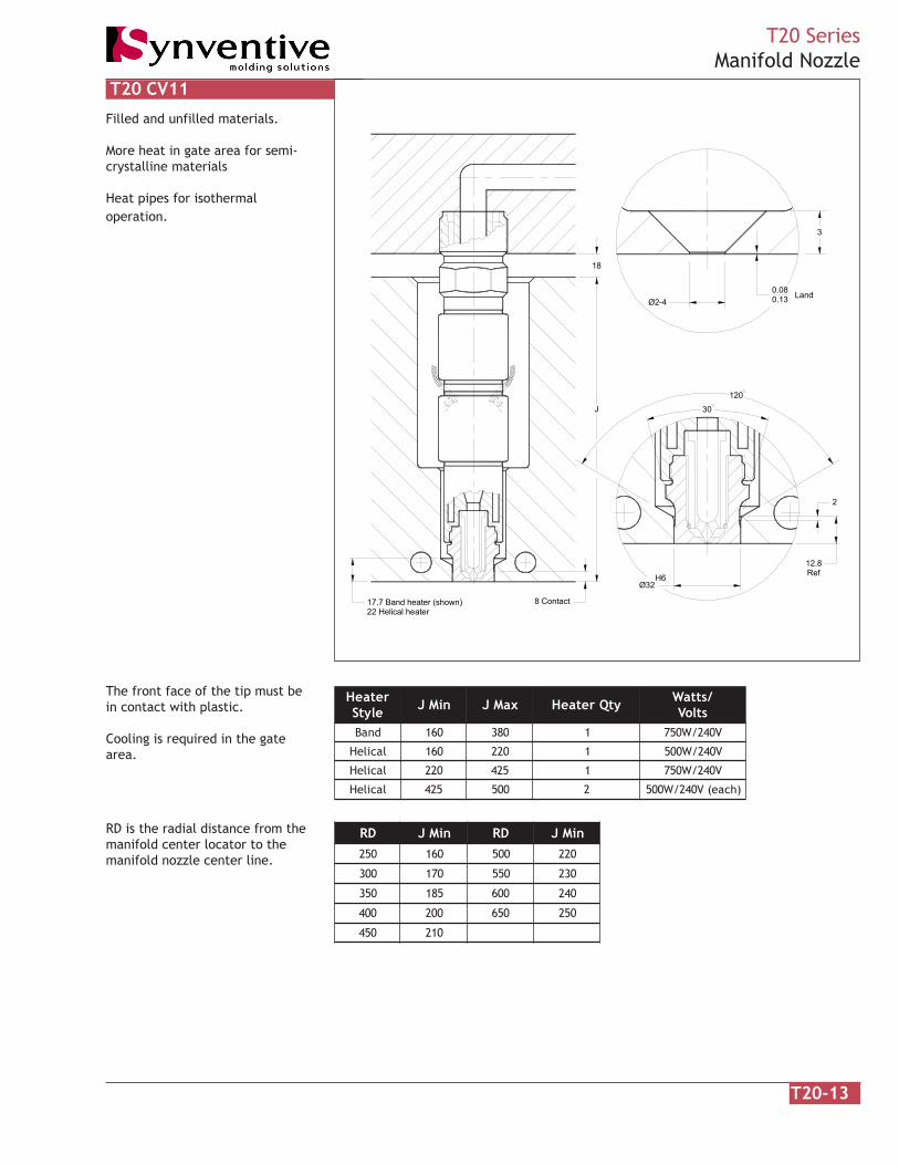
Filled and unfilled materials.
More heat in gate area for semi-crystalline materials
Heat pipes for isothermaloperation.
The front face of the tip must bein contact with plastic.
Cooling is required in the gatearea.
T20 CV11
retaeHelytS niMJ xaMJ ytQretaeH /sttaW
stloVdnaB 061 083 1 V042/W057
lacileH 061 022 1 V042/W005
lacileH 022 524 1 V042/W057
lacileH 524 005 2 )hcae(V042/W005
RD is the radial distance from themanifold center locator to themanifold nozzle center line.
DR niMJ DR niMJ052 061 005 022
003 071 055 032
053 581 006 042
004 002 056 052
054 012
T20-14
T20 SeriesCV11 Recess
Conical Recess
5 Mincontact
Ø17
D
30
0.08
Land0.13Orifice
Recessh
3 Landh Max = 3D = 17 + 3.5(h)
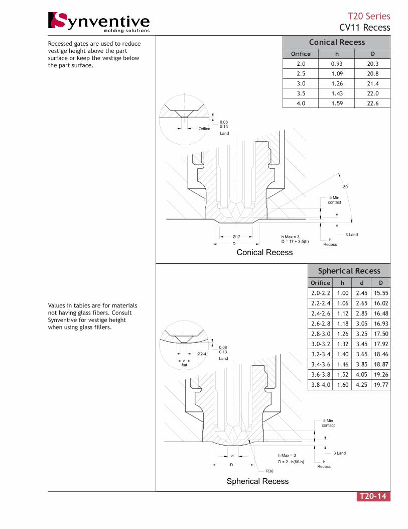
Recessed gates are used to reducevestige height above the partsurface or keep the vestige belowthe part surface.
Values in tables are for materialsnot having glass fibers. ConsultSynventive for vestige heightwhen using glass fillers.
hRecessD
5 Mincontact
3 Land
R30
Spherical Recess
d
dflat
Ø2-40.080.13Land
D = 2 h(60-h)h Max = 3
sseceRlacinoCecifirO h D
0.2 39.0 3.02
5.2 90.1 8.02
0.3 62.1 4.12
5.3 34.1 0.22
0.4 95.1 6.22
sseceRlacirehpSecifirO h d D
2.2-0.2 00.1 54.2 55.51
4.2-2.2 60.1 56.2 20.61
6.2-4.2 21.1 58.2 84.61
8.2-6.2 81.1 50.3 39.61
0.3-8.2 62.1 52.3 05.71
2.3-0.3 23.1 54.3 29.71
4.3-2.3 04.1 56.3 64.81
6.3-4.3 64.1 58.3 78.81
8.3-6.3 25.1 50.4 62.91
0.4-8.3 06.1 52.4 77.91

T20-15
T20 SeriesCV11 Angled Mold Contour
Angled Mold Contour
5 Mincontact
K
L
3
Extension
1.6 Min
0.080.13 Land
E = K + 16TAN
L = 0.13 + K - TAN
27°; K= TAN - 6.530 + Orifice Dia16 27°; K= 5.7TAN + + - 316°; K= TAN
E = TAN32 + Orifice Dia.
L = 0.13
2
Orifice Dia.2
Orifice Dia. - 2
E = K + 16TAN
L = 0.13 + K - TANOrifice Dia.2
1.6COS 2 2
Orifice Dia.2
When gating onto an angled moldcontour the vestige height may beincreased depending on the angle.
K is the increase in vestige heightrequired to maintain 0.13 land, 1.6wall and/or 5 minimum contact.

T20-16
T20 SeriesManifold Nozzle
18
27.8 Band heater (shown)22 Helical heater
8 Contact
Ø32H6
12.8Ref
2
J 30
120
0.080.13 Land
3
Ø4
Filled and unfilled materials.
Developed for PA and PBT.
Heat pipes for isothermaloperation.
The front face of the tip must bein contact with plastic.
Cooling is required in the gatearea.
T20 CV11CM
retaeHelytS niMJ xaMJ ytQretaeH /sttaW
stloVdnaB 061 083 1 V042/W057
)pit(dnaB 061 083 1 V042/W054
lacileH 061 022 1 V042/W005
lacileH 022 524 1 V042/W057
lacileH 524 005 2 )hcae(V042/W005
DR niMJ DR niMJ052 061 005 022
003 071 055 032
053 581 006 042
004 002 056 052
054 012
RD is the radial distance from themanifold center locator to themanifold nozzle center line.

T20-17
T20 SeriesCV11CM Recess
Conical Recess
hRecess
5 Mincontact
Ø17
D
30
Orifice 0.13Land
0.08
3 Landh Max = 3D = 17 + 3.5(h)
Recessed gates are used to reducevestige height above the partsurface or keep the vestige belowthe part surface.
Values in tables are for materialsnot having glass fibers. ConsultSynventive for vestige heightwhen using glass fillers.
hRecessD
5 Mincontact
3 Land
R30
Spherical Recess
d
dflat
Ø2-40.080.13Land
D = 2 h(60-h)h Max = 3
sseceRlacirehpSecifirO h d D
0.4 06.1 52.4 77.91
sseceRlacinoCecifirO h D
0.4 95.1 6.22

T20-18
T20 SeriesCV11CM Angled Mold Contour
5 Mincontact
K
L
3
Extension
1.6 Min
0.080.13
Land
Angled Mold Contour
1.6
2
COS
L = 0.13 + K - TAN
16 27°; K= 5.7TAN + + - 3
Orifice Dia.
16°; K= TAN
E = TAN32 + Orifice Dia.
L = 0.13
2
Orifice Dia.2
E = K + 16TAN
30 + Orifice Dia27°; K= TAN - 6.5
L = 0.13 + K - TAN
E = K + 16TAN
Orifice Dia. - 22
Orifice Dia.2
2
When gating onto an angled moldcontour the vestige height may beincreased depending on the angle.
K is the increase in vestige heightrequired to maintain 0.13 land, 1.6wall and/or 5 minimum contact.

T20-19
T20 SeriesManifold Nozzle
120
90
23.4 Band heater (shown)27.7 Helical heater
120
6.9
18.2 Ref10.1
3 Land
R1.0 R1.5(Typ)
Ø32H6
Ø16.9
Ø21.3
Ø11.4
J
18
Ø2-6
Filled and unfilled materials.
Easy orifice size changes bystraight reaming .
No tip witness mark on part.
Open flow bore.
Heat pipes for isothermaloperation.
Cooling is required in the gatearea.
T20 CV20
retaeHelytS niMJ xaMJ ytQretaeH /sttaW
stloVdnaB 061 083 1 V042/W057
lacileH 061 022 1 V042/W005
lacileH 022 524 1 V042/W057
lacileH 524 005 2 )hcae(V042/W005
RD is the radial distance from themanifold center locator to themanifold nozzle center line.
DR niMJ DR niMJ052 061 005 022
003 071 055 032
053 581 006 042
004 002 056 052
054 012

T20-20
T20 SeriesCV20 Recess
Conical Recessh
Recess
3 LandØ17
D
30
D = 17 + 3.5(h) Max = 3
Recessed gates are used to reducevestige height above the partsurface or keep the vestige belowthe part surface.
For most materials CV10 vestigeheight is equal to 3.0 + orifice/2. Ifthe vestige height relative to thepossible gate recess depth (h) is toogreat, use of a CV11 tip is recom-mended.
orifice2
3.0 + orifice2
Orifice
Values in tables are for materialsnot having glass fibers. ConsultSynventive for vestige heightwhen using glass fillers.
hRecess
DR30
Spherical Recess
D = 2 h(60-h)h Max = 3
3 Land
sseceRlacinoC
h D
0.1 5.02
5.1 3.22
0.2 0.42
5.2 8.52
0.3 5.72
sseceRlacirehpS
h D
0.1 4.51
5.1 7.81
0.2 5.12
5.2 0.42
0.3 2.62

T20-21
T20 SeriesCV20 Angled Mold Contour
K
L
3 Land
1.6 Min4 Min
Angled Mold Contour
L = 3 + K - TANOrifice Dia.
11 30°; K = 5.7TAN + - 3COS
L = 3 - TAN
11°; K = 0
Orifice Dia.2 2
30°; K = 16TAN + - 10.1
Orifice Dia.L = 3 + K - TAN
1.6
2
COS4
When gating onto an angled moldcontour the vestige height may beincreased depending on the angle.
K is the increase in vestige heightrequired to maintain 1.6 wall and/or4 minimum wall thickness.

T20-22
T20 SeriesManifold Nozzle
120
23.4 Band heater (shown)27.7 Helical heater
120
6.9
18.2 Ref
10.1
3 Land
R1.0 R1.5(Typ)
Ø32H6
Ø16.9
Ø21.3
Ø2-40.080.13
Land
Ø11.4
J
18
90
Filled and unfilled materials.
No tip witness mark on part.
More heat in gate area for semi-crystalline materials.
Heat pipes for isothermaloperation.
Cooling is required in the gatearea.
T20 CV21
retaeHelytS niMJ xaMJ ytQretaeH /sttaW
stloVdnaB 061 083 1 V042/W057
lacileH 061 022 1 V042/W005
lacileH 022 524 1 V042/W057
lacileH 524 005 2 )hcae(V042/W005
RD is the radial distance from themanifold center locator to themanifold nozzle center line.
DR niMJ DR niMJ052 061 005 022
003 071 055 032
053 581 006 042
004 002 056 052
054 012

T20-23
T20 SeriesCV21 Recess
hRecess
3
Ø17
D
30
0.080.13
Orifice
Land
D = 17 + 3.5(h)h Max = 3
Conical Recess
Recessed gates are used to reducevestige height above the partsurface or keep the vestige belowthe part surface.
Maintain 0.13 land when machininggate recess.
Values in tables are for materialsnot having glass fibers. ConsultSynventive for vestige heightwhen using glass fillers.
hRecess
DR30
Spherical Recess
d
Orifice
0.080.13
d (flat)
3D = 2 h(60-h)h Max = 3
sseceRlacinoCecifirO h D
0.2 39.0 3.02
5.2 90.1 8.02
0.3 62.1 4.12
5.3 34.1 0.22
0.4 95.1 6.22
sseceRlacirehpSecifirO h d D
2.2-0.2 00.1 54.2 55.51
4.2-2.2 60.1 56.2 20.61
6.2-4.2 21.1 58.2 84.61
8.2-6.2 81.1 50.3 39.61
0.3-8.2 62.1 52.3 05.71
2.3-0.3 23.1 54.3 29.71
4.3-2.3 04.1 56.3 64.81
6.3-4.3 64.1 58.3 78.81
8.3-6.3 25.1 50.4 62.91
0.4-8.3 06.1 52.4 77.91

T20-24
T20 SeriesCV21 Angled Mold Contour
Angled Mold Contour
K 3
1.6 Min4 Min
0.080.13 Land
L
Land
0.080.13
3
L
Orifice Dia.
16 30°; K= 5.7TAN + + TAN - 3
L = 0.13 + K - TAN
2 COS
L = 0.13 2
16°; K= TANOrifice Dia. 1.6COS2
L = 0.13 + K - TANOrifice Dia.2
Orifice Dia. - 2 430°; K= 16TAN + - 10.1
When gating onto an angled moldcontour the vestige height may beincreased depending on the angle.
K is the increase in vestige heightrequired to maintain 0.13 land, 1.6and/or 4.0 minimum wall.

T20-25
T20 SeriesManifold Nozzle
120
33.5 Band heater (shown)27.7 Helical heater
120
6.9
18.2 Ref
10.1
3 Land
R1.0 R1.5(Typ)
Ø32H6
Ø16.9
Ø21.3
0.080.13
Land
Ø11.4
J
18
Ø85
90
Ø4
Filled and unfilled materials.
No tip witness mark on part.
Developed for PA and PBT
Heat pipes for isothermaloperation.
Cooling is required in the gatearea.
T20 CV21CM
retaeHelytS niMJ xaMJ ytQretaeH /sttaW
stloVdnaB 061 083 1 V042/W057
lacileH 061 022 1 V042/W005
lacileH 022 524 1 V042/W057
lacileH 524 005 2 )hcae(V042/W005
RD is the radial distance from themanifold center locator to themanifold nozzle center line.
DR niMJ DR niMJ052 061 005 022
003 071 055 032
053 581 006 042
004 002 056 052
054 012

T20-26
T20 SeriesCV21CM Recess
Ø17
D
30
Land0.130.08
Orifice
Conical recess
Recessh
3
D = 17 + 3.5(h)h Max = 3
Recessed gates are used to reducevestige height above the partsurface or keep the vestige belowthe part surface.
Maintain 0.13 land when machininggate recess.
Values in tables are for materialsnot having glass fibers. ConsultSynventive for vestige heightwhen using glass fillers.
hRecess
D 3R30
Spherical Recess
d
Orifice
0.080.13
d (flat)
D = 2 h(60-h)h Max = 3
sseceRlacinoCecifirO h D
0.4 95.1 6.22
sseceRlacirehpSecifirO h d D
0.4 06.1 52.4 77.91

T20-27
T20 SeriesCV21CM Angled Mold Contour
K
L
3
1.6 Min4 Min
0.080.13 Land
L
Land0.130.08
3
Angled Mold Contour
L = 0.13 + K - TAN
16 30°; K= 5.7TAN + + TAN - 3
Orifice Dia.
16°; K= TANOrifice Dia.
L = 0.13
21.6
COS
2 L = 0.13 + K - TAN
Orifice Dia. - 22
4COS
Orifice Dia.2
30°; K= 16TAN + - 10.1
When gating onto an angled moldcontour the vestige height may beincreased depending on the angle.
K is the increase in vestige heightrequired to maintain 0.13 land, 1.6and/or 4.0 minimum wall.

T20-28
T20 SeriesManifold Nozzle
120
30
H6Ø32
2
12.8Ref
17.7 Band heater (shown)22 Helical heater
8 Contact
15
Ø3.90.13
Pin protrusionR0.13
Ø5
2 Land
18
J
Filled and unfilled materials.
Heat pipes for isothermaloperation.
Tapered valve pin to eliminategate flash.
The front face of the tip must bein contact with plastic.
Cooling is required in the gatearea.
T20 VG12 Tapered
retaeHelytS niMJ xaMJ ytQretaeH /sttaW
stloVdnaB 061 083 1 V042/W057
lacileH 061 022 1 V042/W005
lacileH 022 524 1 V042/W057
lacileH 524 005 2 )hcae(V042/W005
RD is the radial distance from themanifold center locator to themanifold nozzle center line.
DR niMJ DR niMJ052 061 005 022
003 071 055 032
053 581 006 042
004 002 056 052
054 012

T20-29
T20 SeriesVG12 Angled Mold Contour
5 Mincontact
K
2 Land
Extension
1.6 Min
4° 27°; K= 5.7TAN + - 2 4°; K = 0
E = 16TAN E = K + 16TAN
COS1.6 27°; K= 16TAN - 6
E = K + 32TAN -6
Angled Mold Contour
Maximum = 32
R0.13Ø3.9
30
Pin protrusion0.13
K is the increase in vestige heightrequired to maintain 1.6 wall and/or5 minimum contact.

T20-30
T20 SeriesManifold Nozzle
120
30
H6Ø32
2
12.8Ref
17.7 Band heater (shown)22 Helical heater
8 Contact
Ø4.999
0.13Pin protrusionR0.13
2 Land
18
J
Ø5.009
Filled and unfilled materials.
Heat pipes for isothermaloperation.
Straight valve pin in gate for non-adjustable actuators and glassfilled materials.
The front face of the tip must bein contact with plastic.
Cooling is required in the gatearea.
T20 VG12S Straight
retaeHelytS niMJ xaMJ ytQretaeH /sttaW
stloVdnaB 061 083 1 V042/W057
lacileH 061 022 1 V042/W005
lacileH 022 524 1 V042/W057
lacileH 524 005 2 )hcae(V042/W005
RD is the radial distance from themanifold center locator to themanifold nozzle center line.
DR niMJ DR niMJ052 061 005 022
003 071 055 032
053 581 006 042
004 002 056 052
054 012

T20-31
T20 SeriesVG12S Angled Mold Contour
5 Mincontact
K
2 Land
Extension
1.6 Min
0.25 X 45
Ø4.999Ø5.009
R0.13
Pin protrusion0.13
1.6COS4° 27°; K= 5.7TAN + - 2
E = 16TAN
4°; K = 0
E = K + 16TAN E = K + 32TAN -6
27°; K= 16TAN - 6
Angled Mold Contour
K is the increase in vestige heightrequired to maintain 1.6 wall and/or5 minimum contact.

T20-32
T20 SeriesManifold Nozzle
120
90
22.4 Band heater (shown)26.7 Helical heater
120
5.9
17.1
9.1
R1.0 R1.5(Typ)
Ø16.9
Ø5
15
2
0.13Pin protrusion
Ø3.9
Land
R0.13
Ø11.4
J
18
Ø21.3
H6Ø32
Filled and unfilled materials.
No tip witness mark on part.
Heat pipes for isothermaloperation.
Tapered valve pin to eliminategate flash.
Cooling is required in the gatearea.
T20 VG23 Tapered
retaeHelytS niMJ xaMJ ytQretaeH /sttaW
stloVdnaB 061 083 1 V042/W057
lacileH 061 022 1 V042/W005
lacileH 022 524 1 V042/W057
lacileH 524 005 2 )hcae(V042/W005
RD is the radial distance from themanifold center locator to themanifold nozzle center line.
DR niMJ DR niMJ052 061 005 022
003 071 055 032
053 581 006 042
004 002 056 052
054 012
T20-33
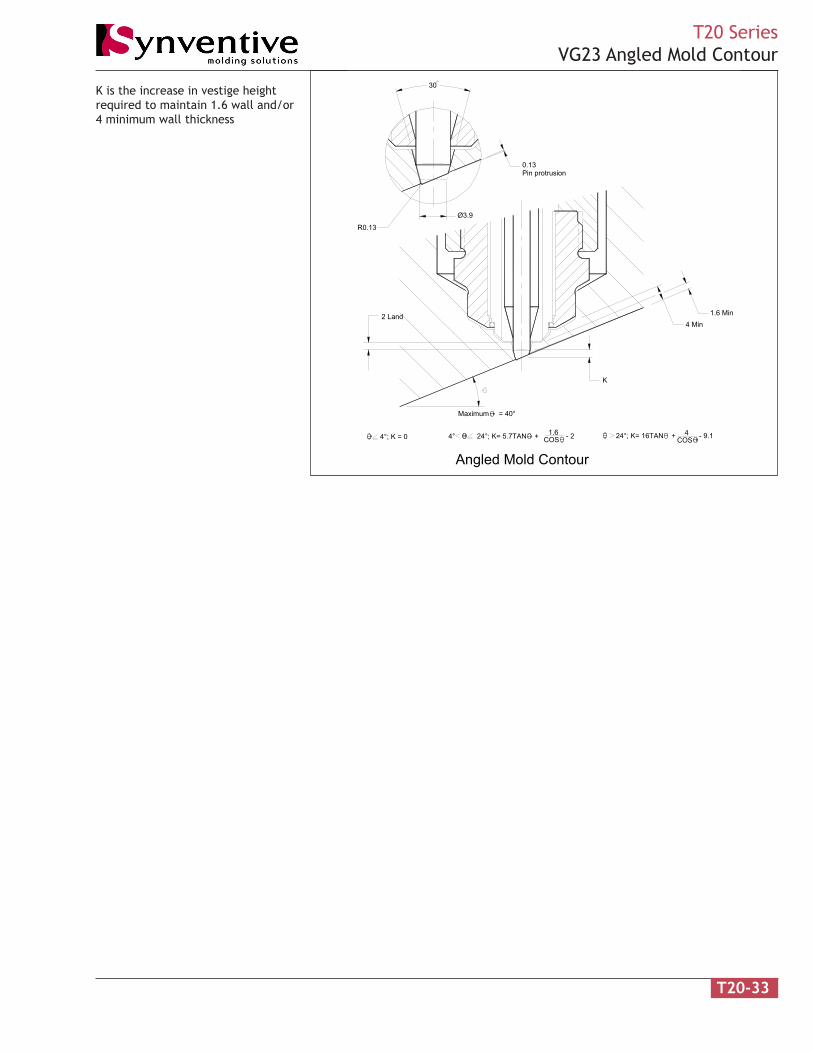
T20 SeriesVG23 Angled Mold Contour
K
2 Land 1.6 Min4 Min
Ø3.9
R0.13
Pin protrusion0.13
30
1.6COS4°; K = 0 4° 24°; K= 5.7TAN + - 2 24°; K= 16TAN + - 9.1COS
4
Maximum = 40°
Angled Mold Contour
K is the increase in vestige heightrequired to maintain 1.6 wall and/or4 minimum wall thickness

T20-34
T20 SeriesManifold Nozzle
120
90
22.4 Band heater (shown)26.7 Helical heater
120
5.9
17.1
9.1
R1.0 R1.5(Typ)
Ø32H6
Ø16.9
Ø21.3
Ø5
2
0.13Pin protrusion
Land
R0.13
Ø11.4
J
18
0.25X 45
Ø4.999Ø5.009
Filled and unfilled materials.
No tip witness mark on part.
Heat pipes for isothermaloperation.
Straight valve pin in gate for non-adjustable actuators and glassfilled materials.
Cooling is required in the gatearea.
T20 VG23S Straight
retaeHelytS niMJ xaMJ ytQretaeH /sttaW
stloVdnaB 061 083 1 V042/W057
lacileH 061 022 1 V042/W005
lacileH 022 524 1 V042/W057
lacileH 524 005 2 )hcae(V042/W005
RD is the radial distance from themanifold center locator to themanifold nozzle center line.
DR niMJ DR niMJ052 061 005 022
003 071 055 032
053 581 006 042
004 002 056 052
054 012

T20-35
T20 SeriesVG23S Angle Contour
K
2 Land 1.6 Min4 Min
0.13Pin protrusion
Ø5.009R0.13
0.25 X 45
Ø4.999
Angled Mold Contour
4COS24°; K= 16TAN + - 9.14° 24°; K= 5.7TAN + - 2 4°; K = 0 1.6
COS
Maximum = 40°
K is the increase in vestige heightrequired to maintain 1.6 wall and/or4 minimum wall thickness