t h i l technical presentation technical presentation important
TRANSCRIPT

1
T h i lT h i l
BOILER WATER TREATMENT
FOR KILN DRY OPERATIONS
Technical Presentation
Technical Presentation
IMPORTANT TOPICS• PRETREATMENT
• TEMPERATURE VS OXYGEN
• FEED WATER / DA
• BOILER WATER
CONDENSATE• CONDENSATE

2
Boiler Water Pretreatment
• Purpose - Statistically 75% of all boiler water problems manifested in the boiler have a rootproblems manifested in the boiler have a root cause in the pretreatment system
• Process - Walk through the processes, key factors, monitoring, and operational impacts of pretreatment systems
• Payoff - Cleaner boilers, increased energy efficiency, reduced maintenance time and costs, increased plant production time and capacity
Pretreatment Methods
• Lime Softeningg
• Ion ExchangeSoftening & Demineralization
• Deaeration:Full Mechanical & HeatersFull Mechanical & Heaters

3
I E hIon Exchange Technology
Ion Exchange
• Purpose of softening. What is it? Why do p g ywe do it?
• How softening occurs
• The regeneration cycle
• Critical factors and troubleshooting• Critical factors and troubleshooting
• Areas of opportunity and operational enhancement

4
• Well and surface water naturally contains calcium and magnesium - referred to as hardness as well as other
Purpose of Softening. What is it? Why do we do it?
giron and manganese that are removed in softening. Examples: Ca, Mg, Fe, Mn, Ba, Al
• These ions adversely impact water and process systems by leading to scaling, corrosion and/or contamination.
$ Removing them improves heat transfer, increases$ Removing them improves heat transfer, increases equipment life, and lowers overall operating costs.
• This process is known as Softening.
Hardness can even make a glass of water taste bad!
How Does Ion Exchange Occur?Top Connection•Operating Inlet•Rinse/Regeneration Inlet•Backwash Outlet
Bottom ConnectionLower Distributor
Upper Distributor / LateralFreeboard
Resin(30 -60 inches)
•Operating Outlet •Rinse/Regeneration Outlet •Backwash InletSupport
(Anthracite or Quartz)
Concrete Subfill

5
Eductor/Pump
RawWater
How Does Ion Exchange Occur?
Eductor/Pump
Meter
BrineTank
SoftWaterWash
In
Rinse
Inlet Back Wash Out
RinseOut
Waste Sump
Exchange Preference
StrongestFerric ironAluminum
How Does Ion Exchange Occur?
Fe+
Mg+Ca+
BariumStrontiumCalciumCopperZincFerrous IronMagnesiumManganesePotassiumAmmonia
Resin
Na+
Na+Na+
Na+
Na+Na+
AmmoniaSodiumHydrogen
WeakestFe+
Mg+Ca+
6
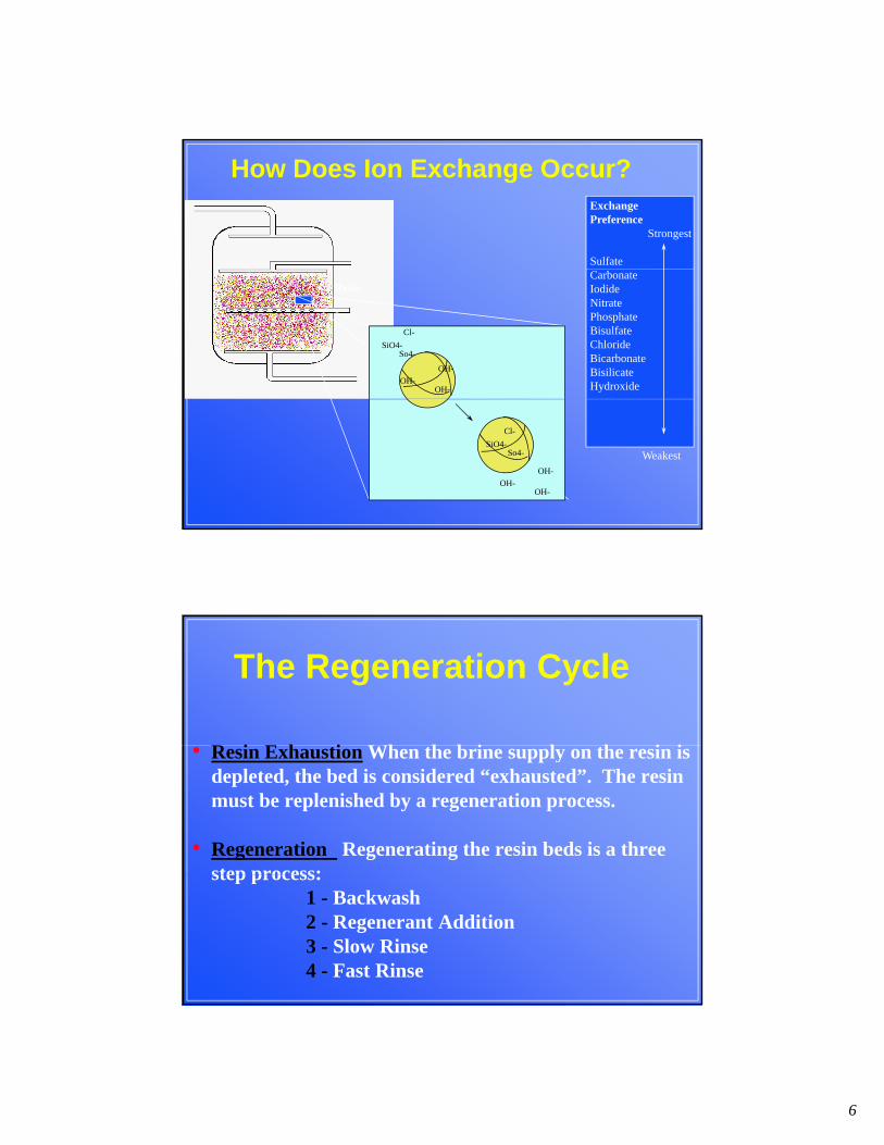
Exchange Preference
Strongest
Sulfate
How Does Ion Exchange Occur?
Cl-
SiO4-So4-
CarbonateIodideNitratePhosphateBisulfateChlorideBicarbonateBisilicate Hydroxide
Resin
OH-
OH-OH-
WeakestOH-
OH-OH-
Cl-
SiO4-So4-
i i i i i
The Regeneration Cycle
• Resin Exhaustion When the brine supply on the resin is depleted, the bed is considered “exhausted”. The resin must be replenished by a regeneration process.
• Regeneration Regenerating the resin beds is a three step process:step process:
1 - Backwash2 - Regenerant Addition3 - Slow Rinse 4 - Fast Rinse

7
•Backwash The purpose is to remove suspended solids and redistribute the bed for even flow to prevent channeling.
•Flow Rate 50% Bed Expansion for Cation Resin
The Regeneration Cycle
•Flow Rate 50% Bed Expansion for Cation Resin75% Bed Expansion for Anion ResinRates are temperature dependent
Before After
Flow
During
Flow
Flow
•Regenerant addition / Slow Rinse The resin is replenished with concentrated Regen. The softening rule is “30/30” (30% brine saturation for 30 minutes in the effluent), @ flow of 1 gpm/ft3, with
The Regeneration Cycle
) @ gp15 minutes of draw and25 minutes of slow rinse.
Water Flow
Brine
Brine Rinse Out

8
•Fast Rinse The excess brine left behind during the slow rinse is removed by flushing the resin bed with a high rate volume of water, @ 1.5-2.5 gpm/ft3 for 15 - 30 minutes.
The Regeneration Cycle
High Volume Water Flow
@ gp
Waste Flush Water
Critical Factors That Affect Run LengthTrouble Shooting
f i• Loss of Resin
• Resin Degradation
• Regeneration Efficiency
• M it i P ti• Monitoring Practices

9
Loss of Resin During Backwash1 Excessive Backwash Flowrate2 Fluctuating Seasonal Temperatures
Critical Factors and Trouble Shooting
Tempe Water % Bed rature (oF) Viscosity (cp) Expansion
4050607080
1.51.31.11.00.8
130100756050
Flow Rate of 6 gpm/ft2
Evaluating• Flowrate should de determined by Flow(gpm) = [ Area(ft2)] [ 3.46 + 0.072 T(oF) ]• 10-20 minutes backwash under proper flow will redistribute the resin bed.• Monitor backwash rates seasonally to ensure temperature fluctuations are compensated.• Measure freeboard annually or use resin traps to ensure resin is not being lost.
Flow
Resin DegradationThere are two degradation that determine resin operating life and throughput capacity:
Critical Factors and Trouble Shooting
Fe /Al Fouling
Oxidation Attack
Cl2,O2

10
Regeneration Efficiency
• To provide full service run lengths the resin
Elution Curve
70%
Ideal Brine Strength (30% for 30 minutes)
Critical Factors and Trouble Shooting
run lengths, the resin must be completely regenerated with brine with both the necessary contact time and regenerant concentration.
30%
40%
50%
60%
70%
% S
atu
rate
d B
rine
Measured Brine Strength exiting Vessel
End Brine Draw
concentration.
0%
10%
20%
0 8 16 24 32 40 48 56 64 72 80 88 96 104
112
Time into Brine/Slow Rinse Step
MONITORING PRACTICES
Efficient use of regenerant and maximum unit reliability can only be ensured by monitoring the indicators that provide insight
Critical Factors and Trouble Shooting
y y g p ginto the unit’s operating performance.
• Outlet Hardness - Dependent upon use
• Throughput -Each run
• Backwash Flow Rate - Semiannually
B k h T t S & Wi t• Backwash Temperature - Summer & Winter
• Resin Level - Annually
• Resin Integrity - 3-5 years
• Regeneration Efficiency - 1 - 2 years

11
Summary / RecapThe factors that affect run length and reliability
Critical Factors and Trouble Shooting
• Loss of Resin
• Resin Degradation
• Regeneration Efficiency
• Monitoring Practices
Areas of Opportunity for Operational Enhancement
1. Reduce foulants that decrease run length- Filter and/or prevent carry over - Fouling treatment
2. Use water unchlorinated or dechlorinated2. Use water unchlorinated or dechlorinated- Reduce oxidant attack of resin
2. Monitoring- Ensuring the unit’s operational performance is being deliveredFor Example: Hardness, Run length, etc.
3. Regeneration Monitoring- Ensuring the unit is regenerated
P ti t- Preventing excess regenerant use4. Seasonal temperature monitoring for backwash adjustments
- Prevent loss of resin through backwash - Prevent accumulation of debris and channeling
5. Resin Integrity evaluation- Ensuring the resin is not fouled or broken down

12
COST IMPACT AREAS
Areas of Opportunity for Operational Enhancement
$ Reduced Potential for Production of Hard Water- Ensures the Prevent of Scaling Operating Equipment
$ Reduced Regenerations - Reduced Regenerant Costs
$ Increased Resin Usage Life - Lower Resin Replacement Costs- Lower Resin Replacement Costs
$ Prevent A Production Bottleneck
Deaerators And Oxygen Removal
Technology

13
Discussion
• What Is Deaeration?
• The Process - Removing O2
• Equipment
• DA Problems
• O ti l I t• Operational Impacts
• Monitoring
What Is It?
• Deaeration is the process of removing oxygen and other noncondensable gases from the boiler feed water like Co2

14
Removing Oxygen
• Water @ 70oF and Atmospheric Pressure Will Have About 7,000 ppb of O2
• A Properly Functioning DA Will Reduce the Level to Approximately 5 - 10 ppb
• The Remaining O2 Is Removed With an Oxygen Scavenger, (i.e. Sulfite etc)
Removing Oxygen
• Three Driving Forcesg1- Heat
(Low Pressure Steam, Condensate)
2- Surface Area (Nozzles, Trays)
3- Pressure(Vent)

15
Removing OxygenRemoving OxygenPrinciple of Surface Area
WaterMultipleDroplet MultipleWaterDroplets
Oxygen
Removing OxygenRemoving Oxygen

16
The Corrosion Process
• Anode: Feo ---> Fe+2 + 2e--
C 2 0 1/ 0 2O• Cathode: 2e-- + H20 + 1/202 --> 2OH-
WaterFe(OH)3
O2
O2 Fe+2
OH-OH-
OH-
Fe(OH)2
Fe+2
Fe Fe
FeFe
e- e- e-e-
e- e-
Anode Cathode
Pitting

17
Water Flow

18
DA Problems• Inadequate Venting
• I d t St Fl St P• Inadequate Steam Flow, Steam Pressure, or Condensate
• Flows Outside of Design Specifications
• Broken, Plugged or Missing Nozzles
• Broken, Plugged or Missing Trays
• Broken or Missing Baffles
19
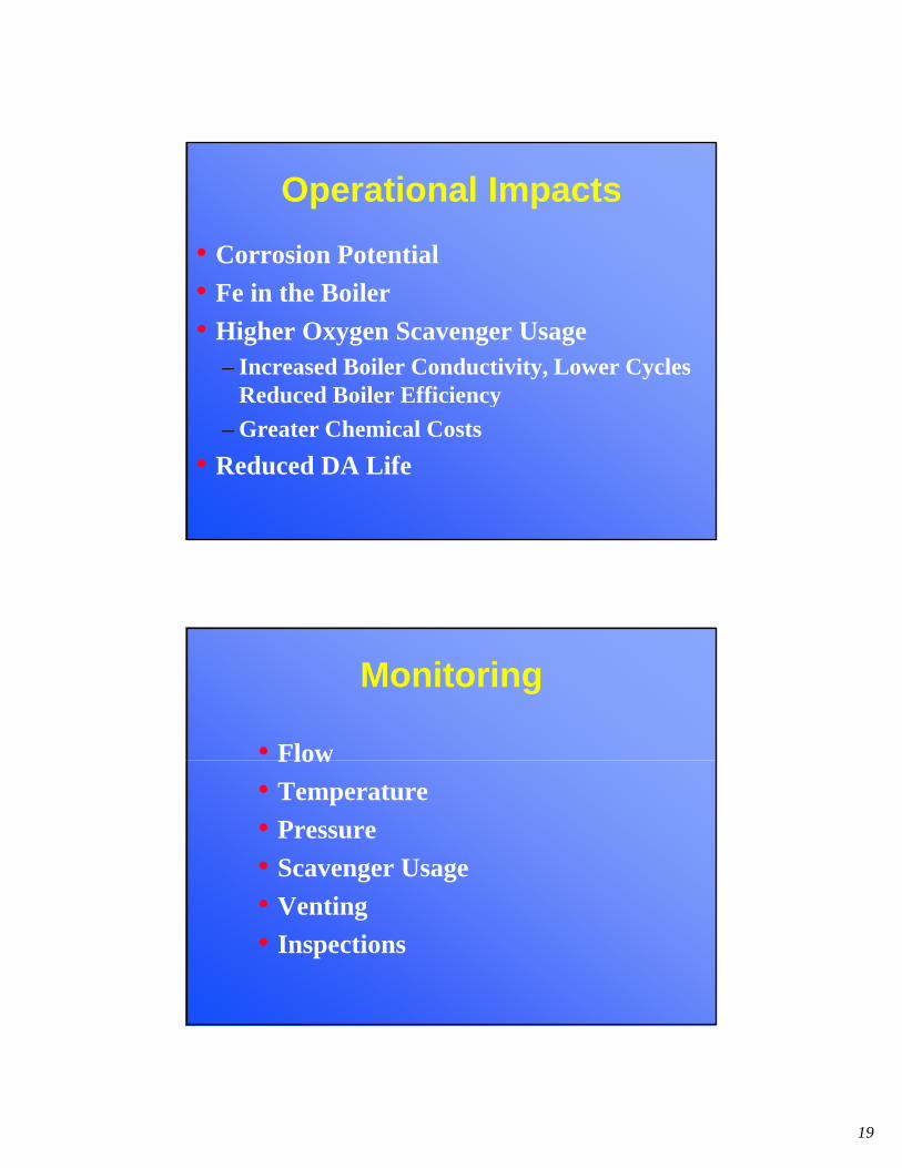
Operational Impacts
• Corrosion Potential
• Fe in the Boiler
• Higher Oxygen Scavenger Usage– Increased Boiler Conductivity, Lower Cycles
Reduced Boiler Efficiencyy
– Greater Chemical Costs
• Reduced DA Life
Monitoring
• FlowFlow
• Temperature
• Pressure
• Scavenger Usage
• Venting
• Inspections

20
Highlights
• Maintain 4” Clearness on Vent
• Change Nozzles Whether They Need It orChange Nozzles Whether They Need It or Not
• Maintain Dome and Storage Within 5oF
• Maintain Temperature/Pressure Within
5oF f S t t d St5oF of Saturated Steam
• Monitor Scavenger Usage
• Clean Trays Annually & Maintain Equipment
Boiler
• Boiler Systems:Boiler Systems:– Boiler Basics
– ASME Guidelines: Water
– Chemical Treatment Options
– Inspection: What you find tells the storyWhat you find tells the storyp y f yy f y– Steam line treatment

21
Boiler Types
• FiretubeFiretube
• Watertube
• Electric
• Once Through
• Nuclear Reactor
Boiler Fuels
• WoodWood
• Coal
• Natural Gas
• Waste Heat
– Furnace Off Gases
– Incinerators
– Etc.
• Nuclear

22
Typical Package Type Boiler
Watertube

23
FIRE TUBE BOILER
Drum Operating Pressure (psig) 0-300
ASME GuidelinesASME GuidelinesIndustrial Fire tube boilers up to Industrial Fire tube boilers up to 300psi 300psi
Drum Operating Pressure (psig) 0 300Feedwater
Dissolved Oxygen before scavenger feed (mg/l O) <0.04Dissolved Oxygen after scavenger feed <0.007
Total iron (mg/l Fe) <0.1Total copper (mg/l Cu) <0.05Total hardness (mg/l CaCO3) <1.0Ph range @ 25°F 7.0-10.5Nonvolatile TOC (mg/l C) <10Oily matter (mg/l) <1
Boiler WaterSilica (mg/l SiO2) <150Total Alkalinity (mg/l CaCO3) <700Free Hydroxide alkalinity (mg/l CaCO3) Not specifiedUnneutralized conductivity(mho/cm @ 25°F)
<7000

24
ASME GuidelinesIndustrial Watertube Boilers up to 900psi
with superheaters & turbine drives
ASME GuidelinesIndustrial Watertube Boilers up to 900psi
with superheaters & turbine drives<300psi <450psi <600psi <750psi <900psi
Dissolved Oxygen (1) <7ppb <7ppb <7ppb <7ppb <7ppb
Total Iron <.1ppm <.05ppm <.03ppm <.025ppm <.02ppm
Total Copper <.05ppm <.025ppm <.02ppm <.02ppm <.015ppm
Total Hardness <.3ppm <.3ppm <.2ppm <.2ppm <.1ppm
Recommended Feedwater Quality
(1) Before Chemical Oxygen Scavenger
ASME GuidelinesASME GuidelinesIndustrial Watertube Boilers up to 900psi Industrial Watertube Boilers up to 900psi
with superheaters & turbine driveswith superheaters & turbine drives
ASME GuidelinesASME GuidelinesIndustrial Watertube Boilers up to 900psi Industrial Watertube Boilers up to 900psi
with superheaters & turbine driveswith superheaters & turbine drives
<300psi <450psi <600psi <750psi <900psi
Silica <150ppm <90ppm <40ppm <30ppm <20ppm
Total Alkalinity (1) <350ppm <300ppm <250ppm <200ppm <150ppm
Conductivity (2) <5400uM <4600uM <3800uM <1500uM <1200uM
Recommended Boiler Water Quality

25
Drum Pressure
(psig)
Boiler water TDS
(ppm TDS)
Boiler water total alkalinity
(ppm as CaCO3)
Boiler water total
suspended solids
(ppm TSS)
Steam purity range (ppm
TDS)
0-300 700-3500 140-700 15 0.2-1.0
301-450 600-3000 120-600 10 0.2-1.0
451-600 500-2500 100-500 8 0.2-1.0
601-750 200-1000 40-200 3 0.1-0.5
751-900 150-750 30-150 2 0.1-0.5
901-1000 125-625 25-125 1 0.1-0.5
1001-1800 100 Dependent on type of boiler water chemical
1 0.1
treatment program
1801-2350 50 Nonedetected
0.1
2351-2600 25 0.05
2601-2900 15 0.05
Types of Programs
• Phosphate Phosphate• Phosphate/Polymer• Chelant/Polymer• Phosphate/Chelant/Polymer• All Polymer• Coordinated pH/Phosphate/Polymer

26
Phosphate PolymerPhosphate Polymer
Boiler Water PolymersC i l hare Crucial to the
Success of anyInternal TreatmentPrograms
In a phosphate precipitation treatment program, the
Phosphate Treatment AloneNot Optimal
magnesium portion of the hardness contamination is precipitated preferentially as magnesium silicate. If silica is not present, the magnesium will precipitate as magnesium hydroxide. If insufficient boiler water alkalinity is being maintained, magnesium can combine with phosphate. Magnesium phosphate has a surface charge that can cause it t dh t t b f d th ll t th lidto adhere to tube surfaces and then collect other solids. For this reason, alkalinity is an important part of a phosphate precipitation program.

27
Hardness controlled b precipitation
Phosphate/Polymer Treatment Characteristics
• Hardness controlled by precipitation• Polymers used to control hardnesssludge and metal oxides
• Phosphate residual used for programcontrol
• Hydroxide alkalinity required Hydroxide alkalinity required(pH : 10.5 -12)
The mechanisms by which boiler
Boiler Water Polymers
water polymers function are
• Complexation / Solubilisation• Crystal modification• Dispersion Dispersion

28
Calcium phosphate,
imagnesium silicatecrystals formed inboiler water withoutwithoutDispersant polymer
Calcium phosphate,magnesium silicatesilicatecrystals formed inboiler water in the presence of a sulphonated polymer

29
Program SelectionConsiderations
• Boiler pressure, design• Pre-treatment plant type• Feedwater quality• Hot well, deaerator type• Steam turbine• Control capabilities• Control capabilities
Phosphate/PolymerTreatmentBoiler Control Parameters
• Phosphate residual as PO4 depending onhardness in the feedwater
• usually associated with boiler pressure• M alkalinity of 700 ppm as CaCO3 • Polymer : min 15 ppm as polymer
S ill h d h d f i l• Still the most used method for treating lowpressure boilers

30
Phosphate/Polymer
Advantages Disadvantagesg
• Tolerates a wide range ofFeed water hardness
• Non corrosive treatment• Suitable for low to
medium pressure systems
g
• Is a precipitationprogram (somedeposition is normal)
• Higher blow down rates may be required
• Easy operator control
Chelant ProgramsChelant Programs
• Require <1ppm BFW HardnessRequire <1ppm BFW Hardness
• Good up to 1000psi
• Clean Program - non precipitating
• Reduced blowdown required
• Chelant corrosion from chemical over-feed

31
Upset ConditionsUpset ConditionsWhat to expect from high BFW hardnessWhat to expect from high BFW hardness
• Chelant Programs– Hard scale:
• Calcium Carbonate
Chelant/Phosphate/PolymerChelant/Phosphate/PolymerTreatmentTreatment
AdvantagesP i il l bili i
DisadvantagesS i it ti i• Primarily a solubilising
treatment• Effective on hardness and iron• May allow reduced blowdown• Increased reliability andefficiency
• Easy and accurate control test
• Some precipitation ispossible
• Potentially corrosiveif misapplied
• Competing ION
• Easy and accurate control test• Tolerates a wide range of
feedwater hardness• Suitable for low to medium
pressure systems

32
• Certain polymers can be effectivecomple ing agents
All Polymer Treatment
complexing agents• Principle mechanism is complexation of
soluble impurities• Secondary mechanism is dispersion of
particulates• Fed to the boiler feed water
Boiler InspectionBoiler InspectionWhat you find tells the storyWhat you find tells the story

33
Boiler ScaleBoiler Scale
What Causes Boiler Scale?What Causes Boiler Scale?Looking inside the drums• Steam drum water lineSteam drum water line
– Erratic indicates high riser velocity \ fireside problem
– Incorrect height inhibits circulation \ control problem
• Scale appearance– Uniform and smooth coating is new, patchiness is old
– Stratified \ intermittent BFW hardness problemStratified \ intermittent BFW hardness problem
– Non-stratified \ continuous BFW hardness problem
• Amount of tube scaling– Wide transition zone indicates circulation problem
– Riser deposition can indicate to much heat

34
What Causes Boiler Scale?What Causes Boiler Scale?
Looking inside the firebox• Firebox flame pattern• Firebox flame pattern
– Heavy impingement inhibits circulation \ firing problem
• Fireside tube slagging– Slagging reduces heat transfer and inhibits circulation
• Missing RefractoryC h h d i l i bl– Can change heat zones and cause circulation problems
A 0.024 inch thick scale on a tube wall increases the input heat required to produce the required steamproduce the required steam by 362F!
Even small amounts of scale are very insulating!
This also increases your yfuel cost!

35
Boiler Deposits
What Causes Boiler Deposit??
• Poor quality boiler feedwater makeup
P t t t t i• Pretreatment system corrosion
• Pretreatment system solids passage
• Condensate system corrosion
• Internal boiler corrosion
• Steam blanketingg
• Improper internal treatment control
• Improper Blowdown

36
Common Deposits in Boilers
Type:• Silica
Typically Caused By:• Steam blanketing \ Low OH \ High BFW Silica• Silica
• Alumina
• Iron Oxide
• Copper
• Steam blanketing \ Low OH \ High BFW Silica
• Steam blanketing \ BFW Alumina
• BFW iron \ Condensate Corrosion \ Preboiler corrosion
• BFW copper \ Condensate Corrosion \Preboiler corrosion
• Sodium Salts
• High Solids
• Evaporation to dryness
• Improper control of TDS
Boiler Corrosion

37
Corrosion Types in Boilers
T i ll C d BType:• Oxygen attack
• Alkalinity concentration
• Acid attack
• Ch l t \ P l
Typically Caused By:• BFW Oxygen
• Concentration of caustic under deposits
• Acid leaks into BFW or condensate
• Excessive chemical concentration• Chelant \ Polymer attack
• Ammonia attack
Excessive chemical concentration
• High ammonia returned in condensate or from BFW
Neutralizing Amines
• Neutralize carbonic acid
• Do not protect against oxygen corrosion
• Maintain condensate pH 8.5-9.0
• Add in direct proportion to amount of CO2 in steam
• Most products are blends of two or more neutralizing amines
• Important operational considerations are volatility, acid neutralization ability, and basicity

38
Neutralizing AminesBasicity - a measure of amine’s ability to raise pH in condensateEnough amine must be added to neutralize all carbonic acidAdditional amine then added to maintain pH
The four most common neutralizing amines (or amine blends) are ammonia AMP
Steam Line Treatment
(or amine blends) are ammonia, AMP, cyclohexylamine, diethylaminoethanol, and morpholine. Neutralizing amines are fed to maintain a pH of 8.2 to 8.6; however, in difficult to control systems a wider pH value of 7.6 to 8.6 may have to be used.

39
Ammonia is used in steam lines where the steam contains a large amount of carbon
Ammonia
steam contains a large amount of carbon dioxide or where there is an appreciable amount of steam loss from the condensate system. The advantage of ammonia is that the relative cost is less than other amines. The disadvantage is that it cannot be used in systems containing copper or nickel.
Cyclohexylamine has been used primarily for low pressure systems
Cyclohexylamine
primarily for low pressure systems (50 down to 5 psi) and also for systems with long condensate runs. This amine has a lower solubility ratio and may cause plugging in the steam line.

40
Diethylaminoethanol also called DEAE is versatile in that the distribution ratio is
Diethylaminoethanol
between that of cyclohexylamine and morpholine making it a very good medium run amine, effective in many industrial condensate systems. The disadvantage is that DEAE is not very effective in low pressure systemssystems.
Morpholine has a low distribution ratio
Morpholine
pand is commonly blended with other amines. The short distribution ratio makes morpholine effective on short run systems and also for the protection of steam turbinesof steam turbines.
41
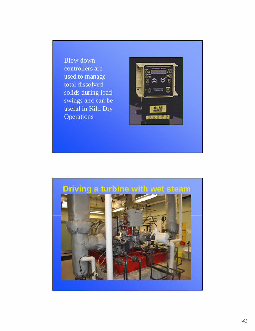
Blow down controllers are used to manageused to manage total dissolved solids during load swings and can be useful in Kiln Dry O tiOperations
Driving a turbine with wet steam

42
Clarity Water Technologies, LLCP.O. Box 1229Twnsp of Washington, NJ 07676
h / i f d lThomas Hageman Partner/Dir of Product DevelopmentDurgin RdChichester, NH 03258603-568-5653