supersonic combustion research at nasa · 2007 fall technical meeting eastern states section of the...
TRANSCRIPT

2007 Fall Technical MeetingEastern States Section of the Combustion Institute
University of VirginiaOctober 21-24, 2007
Supersonic combustion research at NASA
J. Philip Drummond1, Paul M. Danehy2, Daniel Bivolaru3, Richard L. Gaffney4,Sarah A. Tedder5 and Andrew D. Cutler6
1Hypersonic Airbreathing Propulsion Branch2Advanced Sensing and Optical Measurements Branch
3NASA Post-Doctoral Fellow4Hypersonic Air Breathing Propulsion Branch
5NASA Graduate Coop and Research Assistant, College of William and Mary,NASA Langley Research Center, Hampton, Virginia 23681, USA
6Department of Mechanical and Aerospace Engineering, The George Washington University,Newport News, Virginia 23606, USA
This paper discusses the progress of work to model high-speed supersonic reacting flow. The purposeof the work is to improve the state of the art of CFD capabilities for predicting the flow in high-speedpropulsion systems, particularly combustor flowpaths. Theprogram has several components includingthe development of advanced algorithms and models for simulating engine flowpaths as well as a funda-mental experimental and diagnostic development effort to support the formulation and validation of themathematical models. The paper will provide details of current work on experiments that will providedata for the modeling efforts along with the associated nonintrusive diagnostics used to collect the datafrom the experimental flowfield. Simulation of a recent experiment to partially validate the accuracy ofa combustion code is also described.
1 Introduction
The design and development of a propulsion system is accomplished with several levels of ana-lytic tools, ground-based testing and finally flight. This paper will discuss the progress of workto improve the state of the art of CFD capabilities for predicting high-speed reacting flow in en-gines. The research has several components including the development of advanced algorithmsand models for simulating engine flowpaths as well as a fundamental experimental and diagnosticdevelopment effort to support the formulation and validation of the mathematical models. Thepaper will provide details of current work on experiments and the associated non-intrusive diag-nostics that will provide data for the modeling efforts. This effort will lead to the developmentof phenomenological models for Reynolds averaged Navier-Stokes codes, subgrid scale modelsfor large-eddy simulation techniques, and reduced-kinetics models that can then be applied to thedesign of high-speed propulsion systems.
https://ntrs.nasa.gov/search.jsp?R=20080013391 2018-07-14T08:06:26+00:00Z

2 Axisymmetric Coaxial Free Jet Experiments and Related Design Computations
Computational fluid dynamics (CFD) methods that employ the Reynolds-averaged Navier-Stokes(RANS) equations are widely used in the design and analysis ofhypersonic airbreathing engineflow paths. These methods require models of statistical quantities of the turbulence in their de-velopment which have to be empirically calibrated and validated. In particular, new models forturbulent Schmidt and Prandtl number, as well as for turbulence-chemistry interactions, are re-quired [1]. While suitable data is available for low-speed flows with combustion, sufficient datais still lacking in the area of supersonic combustion. Goyneet al. report measurements usingparticle-imaging velocimetry of mean streamwise velocityin a dual-mode scramjet [2]. At theNASA Langley Research Center, several data sets have been acquired in aH2 fueled supersoniccombustor using the coherent anti-Stokes Raman spectroscopy (CARS) technique [3] and the dual-pump CARS technique [4, 5]. The former technique gave temperature only while the latter gaveboth temperature and composition. Data included both mean flow and turbulent statistics, althoughthe uncertainty in the latter was limited by both instrumentprecision and number of measurementsfrom which the statistics were formed. International work in this area includes measurements inscramjet combustors conducted at ONERA (France) and DLR (Germany) using CARS [6], andother non-intrusive techniques.
Available data are limited to only a subset of the important variables (which are temperature, com-position, density and velocity) in a limited number of geometries, and turbulence data are evenrarer. To meet the need for more data, an Interferometric Rayleigh Scattering technique for mea-suring instantaneous velocity is being developed at the NASA Langley Research Center to com-plement the Dual-Pump CARS technique [7,8]. This technique uses Rayleigh scattering from oneof the CARS laser beams to measure velocity in the same instant that CARS measures temperatureand composition. Details on the techniques are given in a later section. Analysis of streams of suchinstantaneous measurements allows formation of the statistical quantities (means, variances, andcovariances) required by modelers. Experimental configurations to provide suitable flow fields arebeing developed. An axisymetric coaxial free jet was selected since it provides the good opticalaccess required for the Rayleigh technique, and symmetry canbe taken advantage of to minimizethe number of required spatial points. In order to form accurate statistics, large numbers of mea-surements are needed at each given point. The use of symmetryallows the total number of mea-surements to be made manageable. Another requirement of theflow field is that it should providedata that is relevant to bothH2- and hydrocarbon-fueled hypersonic air-breathing engines. Theexperiment should be capable of providing flows of various Mach numbers to establish the effectsof compressibility. Finally, it is desirable to be able to create both supersonic combusting flows inwhich the flame is attached to the burner (flame held) and flows in which the flame is detached,since both types of flow can occur in hypersonic engine combustors. Figure 1 shows a schematicand photo of the coaxial free jet experiment. Figure 1(a) shows the burner and nozzle, sectionedalong the axis, without bolts, tubes, spark plug and other fittings shown; Figure 1(b) is an imageof the facility near the nozzle exit during operation, showing the supersonic jet of vitiated air andthe laser beams of the CARS-Rayleigh system. The facility consists of a water-cooled combustionchamber (burner), a silicon carbide nozzle (sonic convergent, or supersonic convergent-divergentfor M=1.6 and M=2), with an exit diameter of 10 mm and a coflow nozzle. Various combinationsof gas flows to the burner are possible. In one set of experiments, H2 or CH4 fuel, air andO2
are reacted to provide vitiated air at various temperatures(dependent on flow rates). In these ex-

Figure 1: The supersonic jet combustor and nozzle. (a) Secti onal view (without bolts, tubes, etc.).(b) Image during CARS-Rayleigh optical system data acquisi tion.
x - inches
Rad
ius
-in
ches
-4 -2 0 2 4 6 8 10
-6
-4
-2
0
2
4
(a) No Co-flow Injection
x - inches
Rad
ius
-in
ches
-4 -2 0 2 4 6 8 10
-6
-4
-2
0
2
4
(b) 15◦ Co-flow injection
Figure 2: OH contours showing the sensitivity of the flame loc ation to the presence of angled co-flow injection.

Inner Jet Outer JetMach No. Heater Operation Mach No. Gas
1, 2 H2+O2+Air vitiated no unreactedH2 oneT◦ off -1, 2 H2+O2+Air vitiated H2 rich variousT◦ off -1, 2 H2+O2+Air vitiated H2 rich variousT◦ ≤1 Air1, 2 H2+O2+Air vitiated O2 rich variousT◦ ≤1 CH4
1, 2 CH4+O2+Air vitiated O2 rich variousT◦ ≤1 CH4
1, 2 H2+O2+Air vitiated O2 rich variousT◦ ≤1 H2
1, 2 CH4+O2+Air vitiated O2 rich variousT◦ ≤1 H2
Table 1: The experimental test matrix
periments, the coflow is of unheatedH2 or CH4, and the result (depending on temperature) is amixing and reacting coaxial jet flow. In another set of experiments, the gas flows to the burner areH2, O2 or N2, and air in such a ratio that the products contain excessH2. The coflow is of airand the result again is a mixing and reacting coaxial jet flow.Depending on temperature and onthe co-flow rate, the flame may be held at the annular base region formed between the central andcoflow nozzle exits where the flow recirculates. Non-reacting cases can also be considered in thecase where there is no excessH2 in the center jet and no fuel in the co-flow.
As part of the design effort, a parametric study of the proposed geometry and run conditions wasconducted using CFD to determine the sensitivity of important experimental quantities, e.g. tem-perature, species, density and velocity, to a number of variables including: inner jet temperature,flame holding base size, co-axial jet injection angle, innerjet Mach number and sensitivity to com-putational values of the turbulent Prandtl and Schmidt numbers. An example calculation using theVulcan CFD code [10] is shown in Figure 2, which shows the sensitivity of the flame location tothe presence of a co-flow. This flow is with a Mach 2, hot hydrogen-rich inner jet without and withcold air co-flow.
Once the experimental geometry was finalized, CFD was used to help define the experimental testmatrix. This matrix, given in Table 1, includes variations in the inner jet Mach number, the tem-perature of the inner jet, the type of fuel (hydrogen or methane), the equivalence ratio of the fueland air and the location of the fuel and air streams (inner jetor co-flow jet). The CFD calculationscompleted in this step provide a baseline to compare with improved models planned for develop-ment using data from this and other experiments in the program. Figure 3 contains tables and flowimages showing the various types of flames that are observed in the actual experiment. Two typesof images are shown: visible light (true color images) with along exposure time, and false colorinfrared (IR) images acquired in the 8 - 9 micron (long wave) region at an exposure time of 10ms. The tables contain information pertaining to the state of the flame: no flame, detached flame,flame held at the base or at the external coflow boundary, and ifthe flame holding is marginal, i.e.,at the point of extinction. Figure 3(a) pertains to cases with H2-vitiated air in the center jet andH2 in the coflow. The center jet sensible enthalpy is varied by adjusting the flow rates from that ofMach 5.5 flight to that of Mach 7, and the exit Mach number of thecenter jet is either 1.0 or 2.0.The coflow is subsonic at the nozzle exit and the equivalence ratio (the ratio ofH2 coflow rate tothat required to consume all theO2 in the center jet,φ) is either 0.5 or 1. (It is not implied that the

Figure 3: Flame state for a matrix of supersonic operating co nditions at sonic and Mach 2 pressurematched exit conditions. Mixed infrared (false color) and v isible light images (two right-most im-ages). (a) Vitiated air center jet with subsonic hydrogen ai r coflow at an overall equivalence ratio φ.( b) Hydrogen rich center jet with sonic coflow of air.
coflowH2 reacts only with theO2 in the center jet.) ForMexit = 1, the flame is held at the exteriorboundary in all cases, whereas, forMexit = 2, in some cases there is no flame and in others theflame is detached (stands off from the nozzle exit), but thereare no cases with flame holding. Witha detached flame, the trend with increasing center jet enthalpy is for the flame to move towards thenozzle exit. Figure 3(b) pertains to cases with excessH2 in the center jet, either 33% or 50% byvolume of the jet flow beingH2. The exit static temperature is increased in increments of 100 K,and the exit Mach number is either 1.0 or 2.0. The coflow of air is sonic and pressure matchedat the exit. In some cases, no flame is observed; in others, detached flames or flames attached atthe base. The trend with increasingTexit and decreasingMexit is from no flame to detached flameto base-attached flame. Thus, a full range of flame behavior isattained which is ideal for modeldevelopment and code validation.
Work has just begun to simulate the axisymmetric coaxial free jet experiment utilizing both RANSand LES codes. This work has not yet been completed. Work has been completed, however,on a coaxial jet mixing experiment that preceded the currentwork, and this experiment has beensimulated using RANS codes. Details of the experiment are described in two earlier papers [11,12].Low-density helium, which serves as a simulant of hydrogen fuel, was chosen to allow detailedstudies of mixing without chemical reaction. Oxygen is added to the helium jet as a diagnosticaid for an oxygen flow-tagging technique (RELIEF). Several methods are utilized to characterizethe flow field including Schlieren visualization, pitot pressure, total temperature, and gas samplingprobe surveying, and RELIEF velocimetry. A schematic of the coaxial jet configuration is shownin Figure 4. The rig consists of a 10 mm inner nozzle from whichhelium, mixed with 5 percentoxygen by volume, is injected at Mach 1.8 and an outer nozzle 60 mm in diameter from whichcoflowing air is introduced also at Mach 1.8. The velocity ratio between the two jets is 2.25, theconvective Mach number is 0.7, and the jet exit pressures arematched to one atmosphere. The

18.261.59
60.47
10.50
10.0015.87
Static pressure tap
76.20
25.40
19.84
15.88
41.91
152.27 Pref, CJ
Helium / 5% Oxygenor Air Tt, CJ
48.01
246.39
Center jet pressure tap
Plenumpressure tapPref, coflow
All dimensions in mm
Screens
AirTt, coflow
24.61
12.66
Figure 4: Coaxial jet assembly cross-section
Figure 5: Schlieren image of coaxial jet mixing (conical ext ension cap removed)
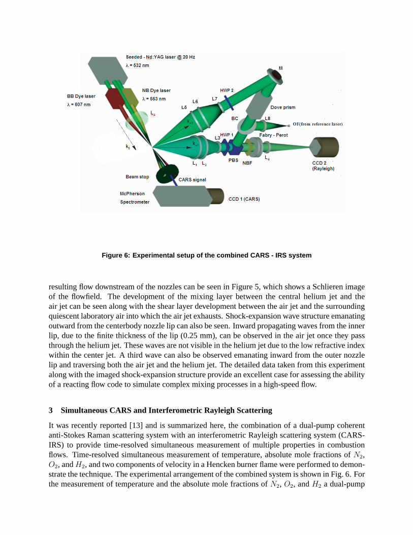
Figure 6: Experimental setup of the combined CARS - IRS syste m
resulting flow downstream of the nozzles can be seen in Figure5, which shows a Schlieren imageof the flowfield. The development of the mixing layer between the central helium jet and theair jet can be seen along with the shear layer development between the air jet and the surroundingquiescent laboratory air into which the air jet exhausts. Shock-expansion wave structure emanatingoutward from the centerbody nozzle lip can also be seen. Inward propagating waves from the innerlip, due to the finite thickness of the lip (0.25 mm), can be observed in the air jet once they passthrough the helium jet. These waves are not visible in the helium jet due to the low refractive indexwithin the center jet. A third wave can also be observed emanating inward from the outer nozzlelip and traversing both the air jet and the helium jet. The detailed data taken from this experimentalong with the imaged shock-expansion structure provide anexcellent case for assessing the abilityof a reacting flow code to simulate complex mixing processes in a high-speed flow.
3 Simultaneous CARS and Interferometric Rayleigh Scattering
It was recently reported [13] and is summarized here, the combination of a dual-pump coherentanti-Stokes Raman scattering system with an interferometric Rayleigh scattering system (CARS-IRS) to provide time-resolved simultaneous measurement of multiple properties in combustionflows. Time-resolved simultaneous measurement of temperature, absolute mole fractions ofN2,O2, andH2, and two components of velocity in a Hencken burner flame wereperformed to demon-strate the technique. The experimental arrangement of the combined system is shown in Fig. 6. Forthe measurement of temperature and the absolute mole fractions ofN2, O2, andH2 a dual-pump
CARS method [4] is used. The system uses spectrally-narrow green (injection seeded Nd:YAG at532 nm) and yellow (NB Dye laser at 552.9 nm) laser pump beams and one spectrally broad redlaser (BB Dye laser at 607 nm) beam as the Stokes beam.
The beams are combined at the focusing point of a spherical lensLc (focal length of 410 mm) ina folded BOXCARS geometry to probe Raman transitions ofN2, O2 andH2. The input beamsplus the coherent blue signal beam at 491 nm are collected andcollimated by another sphericallens with the same focal length asLc. The three input beams are captured in a beam dump whilethe blue signal beam is passed to a spectrometer. The CARS signal, which is a spectrally broadblue beam that containsN2, O2 andH2 spectra, is analyzed by a spectrometer and recorded bythe CCD1 camera. The shape of these spectra provides information on the temperature while therelative intensities of these spectra provide a measure of the relative mole fractions. The spectrumis fit with a theoretical model to determine the temperature and mole fractions.
The velocity measurement is performed simultaneously using an interferometric Rayleigh scatter-ing measurement system [7]. The same pulsed, seeded green laser beam employed in the CARStechnique is used as a narrow-band light source for the Rayleigh scattering system. The receivingoptics for Rayleigh scattering are designed to capture the Rayleigh scattered light from the greenpump beam in the measurement volume while preserving the scattering angle information, and tomix it together with the unshifted light of the laser before it is passed through the interferometer.In this way more than one component of velocity at multiple points can be measured in one in-terferogram [7, 14]. The velocity components measured are those that bisect the angles of laser’sincidence and the collection optics. Since two directions are collected, two velocity componentsare measured. The Rayleigh scattered light from the two measurement directions are combinedwith a polarizing beam splitter (PBS) and directed through a Fabry-Perot etalon and onto a CCDcamera for analysis (CCD2). The particular setup used here gives a range of measurable velocitiesfrom 0 to∼3 km/sec up to temperatures of about 2500 K. The CARS spectra andthe Rayleighspectra are acquired simultaneously by synchronizing the cameras with the green laser Q-switchpulse at 20 Hz. The spectra are subsequently processed, as described in reference [13] to determinethe temperature, composition and velocity. To demonstratethe method, experiments were carriedout in a Hencken burner, which provides an adiabaticH2-air atmospheric pressure flame. Theflame was stabilized with a co-flow ofN2. This flame was used because it provided a challenginghigh-temperature measurement environment while producing a known (near-zero) velocity.
Simultaneous CARS and Rayleigh scattering spectra up to 1610 K are shown in Fig. 7 (a-c) and inFig. 7 (d-f), respectively: (a) and (d) are in the co-flow ofN2, (b) and (e) are in a high temperatureflow containingN2 andO2, and (c) and (f) are in a high temperature flow containingN2 and a lowproportion ofO2. The CARS spectral plots show the experimental data, the theoretical fits, andalso the residual between them. These spectra were used to calculate the rotational-vibrational gastemperature and the mole fraction ofH2, O2, andN2.
For the Fabry-Perot spectra shown in Fig. 7, only one fringe order from each spectrum has beenanalyzed for this paper. The narrow shaped peak, more visible in the spectra of higher temperature,is the reference laser frequency (no Doppler shift). The broader spectrum is the Rayleigh scatteredlight. Each figure contains two Rayleigh and two reference spectra corresponding to the two col-lecting directions V1 (black trace) and V2 (red trace of smaller amplitude), differing by 34 degrees.Two-component velocity measurements in the range of 300-1600 K showed near-zero velocities

Figure 7: Simultaneous spectra of CARS (left) and Rayleigh s cattering from two viewing directions(right). The CARS spectra are both data and fits of theory to th e data. The Rayleigh spectra are datapoints connected by lines
(< 30 m/s) and standard deviations of 30-40 m/s. These errors are about 1% of the dynamic rangeof this measurement system (3,000 m/s). Measurement of one velocity component was shown tobe possible at up to∼2,400 K with this system. These accuracies and precisions are within thedesired range required for the planned supersonic combustion experiments where velocities will beup to 1,500 m/s. However, it is anticipated that future improvements in both hardware and softwarewill allow these errors to be reduced by a factor of two or more.
4 Simulation of Mixing and Reacting Flows
Improved numerical simulation of high-speed propulsion systems and engine performance relieson the development of enhanced codes with an increased capability to model turbulence, turbulentmixing, and kinetics. A significant amount of the design effort utilizes Reynolds averaged Navier-Stokes (RANS) codes for flowpath prediction. RANS design codesutilize phenomenological mod-els to describe the turbulence field, fuel-air mixing, kinetics, and the interaction of turbulence andkinetics. There is an increased reliance on the use of large eddy simulation (LES) for the simulationof high-speed reacting flows [16]. LES methods calculate thelarge scale features of the flowfieldand require modeling only to describe the small scale features of the flow utilizing a subgrid scalemodel. Subgrid scale models using filtered density functions (FDF) have shown great promise inimproving the state-of-the-art in combustor modeling [17]. The FDF method is the counterpart ofthe probability density function (PDF) methodology, whichhas been long-established in RANScalculations of turbulent combustion [18]. The axisymmetric version of the SPARK RANS code

Helium Mass Fraction
y,m
0 0.25 0.5 0.750
0.002
0.004
0.006
0.008
0.01
0.012
0.014
x = 0.0 mx = 0.04303 mx = 0.08121 mx = 0.12074 mx = 0.15000 mx = 0.04293 mx = 0.08110 mx = 0.12080 mx = 0.15080 m
Figure 8: Comparison of helium mass fractiondata (symbols) with simulation results
Pitot Pressure Ratio
y,m
0 0.2 0.4 0.6 0.8 10
0.005
0.01
0.015
0.02
0.025
0.03
x = 0.04303 mx = 0.08121 mx = 0.12074 mx = 0.15000 mx = 0.04293 mx = 0.08110 mx = 0.12080 mx = 0.15080 m
Pref = 579689 Pa
Figure 9: Comparison of pitot pressure datawith simulation results
Streamwise velocity, m/s
y,m
200 400 600 800 1000 12000
0.002
0.004
0.006
0.008
0.01
0.012
0.014
x = 0.00203 mx = 0.04198 mx = 0.08202 mx = 0.12297 mx = 0.15000 mx = 0.00200 mx = 0.04200 mx = 0.08200 mx = 0.12300 mx = 0.15300 m
Figure 10: Comparison of RELIEF velocity data with simulati on results

was used to simulate the flowfield in the helium/oxygen centernozzle and the outer air nozzle ofthe coaxial jet mixing experiment described in the previousexperiment. Details of the code aregiven in reference [19]. The analysis of the experiment was begun by first solving for the flowfieldin the center and outer nozzles. Results obtained at the end ofeach nozzle were then used to spec-ify the supersonic inflow conditions for the downstream domain beyond the nozzles where mixingof the jets occurred. Details regarding the nozzle calculations and the mixing region downstreamof the nozzles are given in reference [20].
A comparison of the measured helium mass fraction data with the simulation results at severalstations downstream of the nozzles is given in Figure 8. Agreement between the simulation andthe data is very good at each station. The code somewhat overpredicts the mixing near the center-line at the x = 0.12 m station, although the prediction improves with increasing radial distance. Acomparison of measured pitot pressures with the simulationis shown in Figure 9. Agreement isgood in the region of the air coflowing jet, but the simulationsomewhat overpredicts the pitot pres-sure in the helium-air mixing region. The comparison with the experimental data differs at largeradial distances greater than 0.025 m as the code does not consider the effects of the laboratory airentrained by the coaxial air jet. The RELIEF streamwise velocity data is compared with the simu-lation in Figure 10. The prediction agrees well with the dataat the first three stations and slightlyoverpredicts the data at the remaining stations near the centerline. The simulation somewhat un-derpredicts the the velocity at the final three stations in the mixing region between the helium andair coflowing jets in agreement with the pitot pressure results.
5 Concluding Remarks
This paper has described work to develop phenomenological models for Reynolds averaged Navier-Stokes codes, subgrid scale models for use in large-eddy simulation and reduced-kinetics mecha-nisms to model hydrogen-air and hydrocarbon-air reaction in propulsion applications. Fundamen-tal experiments are being performed to provide data that will be used in the development and re-finement of these models. Experimental data is extracted from the experiments using nonintrusivediagnostics that allow accurate simultaneous measurementof temperature, species, and up to threecomponents of velocity in supersonic flow without changing the character of the flowfield. Oncethe databases are in hand, the data will be analyzed using a response surface methodology [21–23]that provides an efficient means of determining critical parameters in a chosen model. The modelswill then be incorporated into combustion codes used in engine flowpath analysis and design.
References
[1] Baurle, R.A., “Modeling of High Speed Reacting Flows: Established Practices and Future Challenges,” AIAA2004-267, 42nd Aerospace Sciences Meeting and Exhibit, Reno, NV, 5-8 Jan, 2004.
[2] Goyne, C.P., McDaniel, J.C., Krauss, R.H., Day, S.W., “Velocity measurement in a dual-mode supersonic com-bustor using particle image velocimetry,” AIAA Paper 2001-1761, AIAA/NAL-NASDA-ISAS InternationalSpace Planes and Hypersonic Systems and Technologies Conference, 10th, Kyoto, Japan, Apr. 24-27, 2001.
[3] Cutler, A.D., Danehy, P.M., Springer, R.R., O’Byrne, S., Capriotti, D.P., DeLoach, R., “Coherent Anti-StokesRaman Spectroscopic Thermometry in a Supersonic Combustor,” AIAA J., Vol. 41, No. 12, Dec. 2003.

[4] O’Byrne, S., Danehy, P.M., Cutler, A.D., “Dual-Pump CARS Thermometry and Species Concentration Mea-surements in a Supersonic Combustor,” AIAA Paper 2004-0710, 42nd Aerospace Sciences Meeting, Reno, NV,Jan. 5-8, 2004.
[5] Tedder, S. A., O’Byrne, S., Danehy, P. M., Cutler, A. D., “CARS Temperature and Species Concentration Mea-surements in a Supersonic Combustor with Normal Injection,” AIAA Paper 2005-0616, 43rd AIAA AerospaceSciences Meeting, Reno, NV, Jan 10-13, 2005.
[6] Bresson, A., Bouchardy, P., Magre, P., Grisch, F., “OH/acetone PLIF and CARS thermometry in a supersonicreactive layer,” AIAA Paper 2001-1759, AIAA/NAL-NASDA-ISAS International Space Planes and HypersonicSystems and Technologies Conference, 10th, Kyoto, Japan, Apr. 24-27, 2001.
[7] Bivolaru, D., Danehy, P.M., Lee, J.W., Gaffney, R.L., Cutler, A.D., “Single-pulse, Multi-point Multi-componentInterferometric Rayleigh Scattering Velocimeter,” AIAA-2006-0836, 44th AIAA Aerospace Sciences Meeting,Reno, NV, 9-12 Jan., 2006.
[8] Bivolaru, D., Otugen, M. V., Tzes, A. and Papadopoulos, G., “Image Processing for Interferometric Mie andRayleigh Scattering Velocity Measurements,” AIAA Journal, Vol. 37, No. 6, pp. 688-694, 1999.
[9] Gaffney, Richard L. Jr., Cutler, Andrew D., “CFD Modeling Needs And What Makes A Good Supersonic Com-bustion Validation Experiment,” JANNAF CS/APS/PSHS/MSS Joint Meeting, Charleston, SC, June, 2005.
[10] White, J. A. and Morrison, J. H., “A Pseudo-Temporal Multi-Grid Relaxation Scheme for Solving the ParabolizedNavier-Stokes Equations,” AIAA paper no. 99-3360, June, 1999.
[11] Cutler, A. D., Carty, A., Doerner, S., Diskin, G., and Drummond, J. P., Supersonic Coaxial Jet Flow Experimentfor CFD Code Validation. AIAA Paper 99-3588, June 1999.
[12] Cutler, A. D., and White, J. A., An Experimental and CFD Study of a Supersonic Coaxial Jet. AIAA Paper2001-0143, January 2001.
[13] D. Bivolaru, P. M. Danehy, K. D. Grinstead, Jr., S. Tedder, A. D. Cutler, “Simultaneous CARS and Interfero-metric Rayleigh Scattering,” AIAA AMT-GT Technology Conference, San Francisco, AIAA-2006-2968 June(2006).
[14] Bivolaru, D., Danehy, P. M., and Lee, J. W, “IntracavityRayleigh-Mie Scattering for multipoint, two-componentvelocity measurement,” Optics Letters, Vol. 31, No. 11, pp.1645-1647, June, 2006.
[15] Cutler, A. D., Danehy, P. M., Byrne, P.O., Rodriguez, C.G., and Drummond, J. P., “Supersonic CombustionExperiments for CFD Model Development and Validation,” AIAA 2004-0266, 2004.
[16] Janicka, J. and Sadiki, A., Large eddy simulation of turbulent combustion systems.Proc. Combust. Inst. 30(2005) 537–547.
[17] Givi, P., Filtered density function for subgrid scale modeling of turbulent combustion.AIAA J. 44(1) (2006)16–23.
[18] Pope, S. B.,Turbulent Flows. Cambridge, UK: Cambridge University Press (2000).
[19] Drummond, J. P., Numerical Simulation of a Supersonic Chemically Reacting Mixing Layer. NASA TM 4055,1988.
[20] Drummond, J. P., Diskin, G. S. and Cutler, A. D., Fuel-Air Mixing and Combustion in Scramjets. AIAA Paper02-3878, July 2002.
[21] Box, G.E.P. and Wilson, K.B., “On the Experimental Attainment of Optimum Conditions,”Journal of the RoyalStatistical Society Ser.B, 13, pp. 195–241, 1951.
[22] Montgomery, D. C. ,Design and Analysis of Experiments, 6th edition, John Wiley & Sons, 2004.
[23] Myers, R. H. and Montgomery, D. C.,Response Surface Methodology: Process and Product Optimization UsingDesigned Experiments, 2nd edition, John Wiley & Sons, 2002.