supercapacitors and battery power management for hybrid vehicle applications using multi boost and...
TRANSCRIPT
A Mini Project Report
ON
“SUPERCAPACITORS AND BATTERY POWER MANAGEMENT FOR HYBRID
VEHICLE APPLICATIONS USING MULTI BOOST AND FULL BRIDGE
CONVERTERS”
Is submitted in the partial fulfillment for the award of the degree of
BACHELOR OF TECHNOLOGYIN
ELECTRICAL AND ELECTRONICS ENGINEERING
By
M.KRISHNAVENI 11B71A0206
A.PRADEEP 11B71A0244
E.SOUMYA 11B71A0249
P.SRINIVAS 11B71A0246
UNDER THE GUIDANCE OF
Mrs. M.PADMA
Asst. Professor
DEPARTMENT OF ELECTRICAL & ELECTRONICS ENGINEERING
SINDHURA COLLEGE OF ENGINEERING & TECHNOLOGY
Approved by AICTE New Delhi, affiliated to JNTUH, Hyderabad.
Medipally, Godhavarikhani, Ramagundam (M), Karimnagar (D), T.S.
During the academic year 2011-2015.

SINDHURA COLLEGE OF ENGINEERING & TECHNOLOGY
(Approved by AICTE New Delhi, affiliated to JNTUH, Hyderabad)
DEPARTMENT OF ELECTRICAL & ELECTRONICS ENGINEERING
CERTIFICATE
This is to certify that the mini project report entitled “Super Capacitor & Battery Power Management For Hybrid Vehicle Application Using Multi Boost & Full Bridge Converters” is submitted in the partial fulfillment for the award of the degree of BACHELOR OF TECHNOLOGY in ELECTRICAL AND ELECTRONICS ENGINEERING.
By
M.KRISHNAVENI 11B71A0206
A.PRADEEP 11B71A0244
E.SOUMYA 11B71A0249
P.SRINIVAS 11B71A0246
Bonafide students of SINDHURA COLLEGE OF ENGINEERING & TECHNOLOGY
During the academic year 2014-2015.
Mrs. M.PADMA Mr. J.MADHUKAR REDDY
INTERNAL GUIDE H.O.D, EEE Dept
Mr. R.NARAYAN DAS EXTERNAL EXAMINER
PRINCIPAL

DECLARATION
We the students of B.Tech in Electrical & Electronics Engineering, Sindhura
college of Engineering & Technology, Ramagundam, hereby declare that the Mini Project
entitled “SUPER CAPACITOR & BATTERY POWER MANAGEMENT FOR
HYBRID VEHICLE APPLICATION USING MULTI BOOST & FULL BRIDGE
CONVERTERS” is the original work carried out by us to the best of my knowledge and
belief. We hereby declare that this mini project bears no resemblance to any other project
submitted at Sindhura college of Engineering & Technology, Ramagundam or any other
colleges affiliated JNTUH for the award of the degree.
By
M.KRISHNAVENI 11B71A0206
A.PRADEEP 11B71A0244
E.SOUMYA 11B71A0249
P.SRINIVAS 11B71A0246

ACKNOWLEDGEMENT
The development of the project through an arduous task has been made easier with
the cooperation of many people. We are pleased to express thanks to the people whose
suggestions, comments and criticisms greatly encouraged in the betterment of the project.
We are very grateful to Mr. R.Narayan Das, Principal, Sindhura College of
Engineering & Technology for providing the required facilities in the college campus.
We express our sincere thanks to Mr. J.Madhukar Reddy, Associate Professor &
Head of the Department of Electrical and Electronics Engineering for the constant
cooperation and constructing, criticism, throughout the project.
We express our sincere thanks to our guide Mrs. M.Padma, Assistant Professor for
his valuable guidance, involvement and the interest shown by him on us has been the main
inspiration for the successful completion of the project.
We would also thank all the staff of Department of Electrical & Electronics Engineering and
Project Review Committee (PRC) members, who are helped us directly or indirectly for the successful
completion of the project.
We earnestly thank my Parents, Family and Friends for their constant encouragement and
moral support, which made the project work successful.
By
M.KRISHNAVENI 11B71A0206
A.PRADEEP 11B71A0244
E.SOUMYA 11B71A0249
P.SRINIVAS 11B71A0246

ABSTRACT
This project presents super capacitors and battery association methodology for ECCE
Hybrid vehicle. ECCE is an experimental Hybrid Vehicle developed at L2ESLaboratory in
collaboration with the Research Centre in Electrical Engineering and Electronics in Belfort
(CREEBEL) and other French partners. This test bench has currently lead-acid batteries with
a rated voltage of 540 V, two motors each one coupled with one alternator. The alternators
are feeding a DC-bus by rectifiers.
The main objective of this paper is to study the management of the energy provides
by two super capacitor packs. Each super capacitors module is made of 108 cells with a
maximum voltage of 270V. This experimental test bench is carried out for studies and
innovating tests for the Hybrid Vehicle applications.
The multi boost and multi full bridge converter topologies are studied to define the
best topology for the embarked power management. The authors propose a good power
management strategy by using the multi boost and the multi full bridge converter topologies.
The simulation results of the two converter topologies are presented.

INDEX
S.NO TITLE PAGE NO
1. INTRODUCTION 12. SUPER CAPACITORS 2
2.1 Super Capacitor Construction 22.2 Equivalent Circuit 52.3 How to Measure the Capacitance 52.4 Capacitance 62.5 Life Expectancy 72.6 Applications for Super capacitors 72.7 Importance of Proper Design of SCES and Future Scope of Work 8
3. BOOST CONVERTER 93.1 Block Diagram 103.2 Operating Principle 103.3 Applications of Boost Converter 15
4. ELECTRIC VEHICLE 164.1 Vehicle Types 174.2 Advantages of Electric Vehicles 19
5. FULL BRIDGE CONVERTER 215.1 Half-Wave Rectifier 215.2 Full-Wave Rectifier 225.3 Peak Loss 245.4 Rectifier Output Smoothing 245.5 Voltage Doubling Rectifier 255.6 Basic Operation 265.7 Output Smoothing 27
6. POWER MANAGEMENT 306.1 Power Management System Helps To 31
7. DC/DC CONVERTER TOPOLOGIES & MODELING 337.1 Multi Boost & Multi Full Bridge Converters Modelling 337.2 Full Bridge Converter Simulation Results For Np=2 35
8. SIMULINK DIAGRAM 379. DESIGN AND EXPERIMENTAL RESULTS 39
9.1 Experimental Setup at Reduced Scale 409.2 Boost Converter Simulation & Experimental Results 41CONCLUSION 43REFERENCES 44

LIST OF FIGURES
FIG.NO FIGURE NAME PAGE NO
1 Converter Topologies for ECCE Hybrid Vehicle 1
2.1(a) Activated carbon electrodes 3
2.1(b) Series RC Circuit with Parallel Resistance 3
2.2(a) Supercapacitor Equivalent Circuit 5
2.2(b) Equivalent circuit 5
2.3 Charge and Discharge Method 6
3 Circuit Diagram of Boost Converter 9
3.1 Block diagram of Boost Converter 10
3.2(a) Boost converter schematic 10
3.2(b) Two Configurations of a Boost Converter,
Depending on the State of the Switch S 11
3.2(c) Waveforms of Current and Voltage in a
Boost Converter Operating In Continuous Mode 12
3.2(d) Waveforms of Current and Voltage in a Boost Converter
Operating In Discontinuous Mode 14
4 Electric vehicle/hybrid electric system using super capacitors 17
5.1 Half Wave Rectifier Circuit, I/P & O/P Wave Forms 21
5.2(a) Full Wave Rectifier with Non-center Tapped Transformer 22
5.2(b) Full Wave Rectifier with Centre Tapped Transformer 22
5.2(c) A Three-phase Bridge Rectifier 23
5.2(d) 3-phase AC input, Half & Full Wave Rectified
DC Output Waveforms 23
5.4 RC-Filter Rectifier 24
5.5 Cockcroft Walton Voltage Multiplier 26
5.6 AC, Half-wave and Full Wave Rectified Signals 27
5.7(a) Three Phase Bridge Rectifier 29

5.7(b) 3-Phase AC input Waveform, Half-wave Rectified Waveform
& Full-wave Rectified Waveform 29
7.1(a) (a) Multi boost Converter Topology &
(b) Multi Full Bridge Converter Topology 33
7.1(b) (a) Multi Boost Control Strategy &
(b) Multi Full Bridge Control Strategy 34
7.2(a) (a) Super Capacitor Modules Voltages,
(b) Super Capacitor Modules Currents 35
7.2(b) (a) Battery current control result
(b) DC-link and active load currents 36
8 (a) Boost converter circuit 37
8 (b) Full bridge converter circuit 38
9 Full Bridge Converter with Chopping Devices 39
9.1 Boost and Full Bridge Converters Experimental Setup 41
9.2(a) Super Capacitor Modules Experimental and
Simulation Voltage Results 41
9.2(b) Super Capacitor Modules Experimental and
Simulation Current Results 42
9.2(c) DC-link voltage and current experimental validation 42

LIST OF TABLES
TABLE.NO TABLE NAME PAGE NO
Table 1 Full bridge Topology Simulations Parameters 36
Table 2 Full bridge Experimental parameters 39

1. INTRODUCTION
In the last few years the pollution problems and the increase of the cost of fossil
energy (oil, gas) have become planetary problems. The car manufacturers started to react
to the urban pollution problems in nineties by commercializing the electric vehicle. But
the battery weight and cost problems were not solved. The batteries must provide energy
and peaks power during the transient states. These conditions are severe for the batteries.
To decrease these severe conditions, the super capacitors and batteries associate with a
good power management present a promising solution.
Super capacitors are storage devices which enable to supply the peaks of power to
hybrid vehicle during the transient states. During the steady states, batteries will provide
the energy requested. This methodology enables to decrease the weight and increases the
lifespan of the batteries. Hybridization using batteries and super capacitors for transport
applications is needed when energy and power management are requested during the
transient sates and steady states. The multi boost and multi full bridge converters will be
investigated because of the high power. For range problems, traction batteries used until
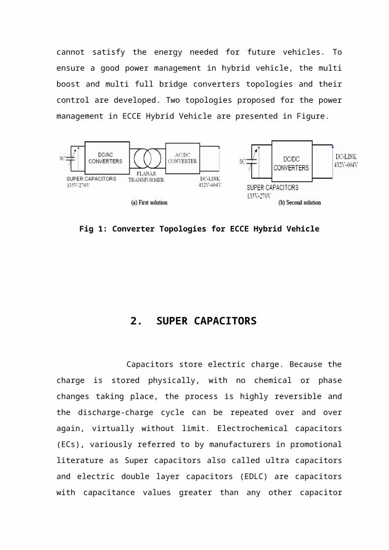
now cannot satisfy the energy needed for future vehicles. To ensure a good power
management in hybrid vehicle, the multi boost and multi full bridge converters topologies
and their control are developed. Two topologies proposed for the power management in
ECCE Hybrid Vehicle are presented in Figure.
Fig 1: Converter Topologies for ECCE Hybrid Vehicle

2. SUPER CAPACITORS
Capacitors store electric charge. Because the charge is stored physically, with no
chemical or phase changes taking place, the process is highly reversible and the discharge-
charge cycle can be repeated over and over again, virtually without limit. Electrochemical
capacitors (ECs), variously referred to by manufacturers in promotional literature as Super
capacitors also called ultra capacitors and electric double layer capacitors (EDLC) are
capacitors with capacitance values greater than any other capacitor type available today.
Capacitance values reaching up to 400 Farads in a single standard case size are available.
Supercapacitors have the highest capacitive density available today with densities so high
that these capacitors can be used to applications normally reserved for batteries.
Supercapacitors are not as volumetrically efficient and are more expensive than batteries
but they do have other advantages over batteries making the preferred choice in
applications requiring a large amount of energy storage to be stored and delivered in bursts
repeatedly.
The most significant advantage supercapacitors have over batteries is their ability to
be charged and discharged continuously without degrading like batteries do. This is why
batteries and super capacitors are used in conjunction with each other. The supercapacitors
will supply power to the system when there are surges or energy bursts since
supercapacitors can be charged and discharged quickly while the batteries can supply the
bulk energy since they can store and deliver larger amount energy over a longer slower
period of time.
2.1 Super Capacitor Construction:
What makes super capacitors different from other capacitors types are the
electrodes used in these capacitors. Supercapacitors are based on a carbon (nano tube)
technology. The carbon technology used in these capacitors creates a very large surface
area with an extremely small separation distance. Capacitors consist of 2 metal electrodes
separated by a dielectric material. The dielectric not only separates the electrodes but also
has electrical properties that affect the performance of a capacitor. Supercapacitors do not
have a traditional dielectric material like ceramic, polymer films or aluminum oxide to
separate the electrodes but instead have a physical barrier made from activated carbon that

when an electrical charge is applied to the material a double electric field is generated
which acts like a dielectric. The thickness of the electric double layer is as thin as a
molecule. The surface area of the activated carbon layer is extremely large yielding several
thousands of square meters per gram. This large surface area allows for the absorption of a
large amount of ions.
The charging/discharging occurs in an ion absorption layer formed on the electrodes
of activated carbon.
The activated carbon fiber electrodes are impregnated with an electrolyte where
positive and negative charges are formed between the electrodes and the impregnant. The
electric double layer formed becomes an insulator until a large enough voltage is applied
and current begins to flow. The magnitude of voltage where charges begin to flow is
where the electrolyte begins to break down. This is called the decomposition voltage
Fig 2.1(a): Activated carbon electrodes
The double layers formed on the activated carbon surfaces can be illustrated as a
series of parallel RC circuits.
As shown below the capacitor is made up of a series of RC circuits where R1, R2
…Rn are the internal resistances and C1, C2..., Cn are the electrostatic capacitances of the
activated carbons.
Fig 2.1(b): Series RC Circuit with Parallel Resistance

When voltage is applied current flows through each of the RC circuits. The amount of
time required to charge the capacitor is dependent on the CxR values of each RC circuit.
Obviously the larger the CxR the longer it will take to charge the capacitor. The
amount of current needed to charge the capacitor is determined by the following equation:
In= (V/Rn) exp (-t/ (Cn*Rn))
Super capacitor is a double layer capacitor; the energy is stored by charge transfer
at the boundary between electrode and electrolyte. The amount of stored energy is
function of the available electrode and electrolyte surface, the size of the ions, and the
level of the electrolyte decomposition voltage. Supercapacitors are constituted of two
electrodes, a separator and an electrolyte. The two electrodes, made of activated carbon
provide a high surface area part, defining so energy density of the component. On the
electrodes, current collectors with a high conducting part assure the interface between the
electrodes and the connections of the super capacitor. The two electrodes are separated by
a membrane, which allows the mobility of charged ions and forbids no electronic contact.
The electrolyte supplies and conducts the ions from one electrode to the other.
Usually super capacitors are divided into two types: double-layer capacitors and
electrochemical capacitors. The former depends on the mechanism of double layers, which
is result of the separation of charges at interface between the electrode surface of active
carbon or carbon fiber and electrolytic solution. Its capacitance is proportional to the
specific surface areas of electrode material. The latter depends on fast faraday redox
reaction. The electrochemical capacitors include metal oxide supercapacitors and
conductive polymer supercapacitors. They all make use of the high reversible redox
reaction occurring on electrodes surface or inside them to produce the capacitance
concerning with electrode potential. Capacitance of them depends mainly on the
utilization of active material of electrode. The working voltage of electrochemical
capacitor is usually lower than 3 V. Based on high working voltage of electrolytic
capacitor, the hybrid super-capacitor combines the anode of electrolytic capacitor with the
cathode of electrochemical capacitor, so it has the best features with the high specific
capacitance and high energy density of electrochemical capacitor. The capacitors can work
at high voltage without connecting many cells in series. The most important parameters of
a super capacitor include the capacitance(C), ESR and EPR (which is also called leakage
resistance).
2.2 Equivalent Circuit:
Super capacitors can be illustrated similarly to conventional film, ceramic or
aluminum electrolytic capacitors
Fig 2.2 (a):Supercapacitor Equivalent Circuit
This equivalent circuit is only a simplified or first order model of a super capacitor.
In actuality supercapacitors exhibit a non ideal behavior due to the porous materials used
to make the electrodes. This causes supercapacitors to exhibit behavior more closely to
transmission lines than capacitors. Below is a more accurate illustration of the equivalent
circuit for a super capacitor.
Fig 2.2(b): Equivalent circuit
2.3 How To Measure The Capacitance:
There are a couple of ways used to measure the capacitance of supercapacitors.
1. Charge method
2. Charging and discharging method.
Charge Method:
Measurement is performed using a charge method using the following formula.
C=t/R
t= .632Vo where Vo is the applied voltage.

Fig 2.3: Charge and Discharge Method
This method is similar to the charging method except the capacitance is calculated during
the discharge cycle instead of the charging cycle.
Discharge time for constant current discharge
t= Cx (V0-V1)/I
Discharge time for constant resistance discharge
t= CRln (V1/V0)
Where t= discharge time, V0= initial voltage, V1= ending voltage, I= current.
2.4 Capacitance
Super capacitors have such large capacitance values that standard measuring
equipment cannot be used to measure the capacity of these capacitors.
Capacitance is measured per the following method:
1. Charge capacitor for 30 minutes at rated voltage.
2. Discharge capacitor through a constant current load.
3. Discharge rate to be 1mA/F.
4. Measure voltage drop between V1 to V2.
5. Measure time for capacitor to discharge from V1 to V2.
6. Calculate the capacitance using the following equation:
C= I*(T2-T1)
V1-V2
Where V1=0.7Vr, V2=0.3Vr (Vr= rated voltage of capacitor)

ESR
AC ESR - Measure using a 4 probe impedance analyzer at 1 kHz.
DC ESR - measured using the following procedure
1. Charge capacitor using a constant current.
2. After reaching rated voltage hold voltage for at least 1 minute.
3. Discharge capacitor at a rate of 1mA/F.
4. Measure the time it takes to have the voltage drop from V1 to V2.
5. Calculate ESR using the following formula:
ESR (DC) = VI
2.5 Life Expectancy
The life expectancy of supercapacitors is identical to aluminum electrolytic
capacitors. The life of supercapacitors will double for every 10°C decrease in the ambient
temperature the capacitors are operated in. Supercapacitors operated at room temperature
can have life expectancies of several years compared to operating the capacitors at their
maximum rated temperature.
L2=L1*2X X=Tm-Ta/2
L1= Load life rating of the super capacitor.
L2= expected life at operating condition.
Tm= Maximum temperature rating of the supercapacitor.
Ta= Ambient temperature the supercapacitor is going to be exposed to in the application.
2.6 Applications for Supercapacitors
Supercapacitors have found uses include:
• Computer systems
• UPS systems
• Power conditioners
• Welders
• Inverters

• Automobile regenerative braking systems
• Power supplies
• Cameras
• Power generators
2.7 Importance of Proper Design of SCES and Future Scope of Work
The utmost requirement of proper design and implementation of SCES is
maintaining the reliability of the power distribution system in the grid connected mode,
the switching transient mode, the island mode. This is also important in various analyses
such as sustained interruptions, voltage flicker, voltage sags, harmonics, voltage
regulation, voltage stability. There are other different aspects related to power distribution
system where the storage study is essential, some are listed as follows.
1. Calculation of load schedule,
2. Optimal use of non-conventional energy sources,
3. Dispatch ability of Power,
4. Ride trough capability of Supply
5. Reduced insulation,
6. Transformer connections and ground faults,
7. Design of system elements: transformer, feeders.

3. BOOST CONVERTER
A boost converter (step-up converter) is a power converter with an output DC
voltage greater than its input DC voltage. It is a class of switching-mode power supply
(SMPS) containing at least two semiconductor switches (a diode and a transistor) and at
least one energy storage element. Filters made of capacitors (sometimes in combination
with inductors) are normally added to the output of the converter to reduce output voltage
ripple.
Fig 3:Circuit Diagram of Boost Converter
Power can also come from DC sources such as batteries, solar panels, rectifiers and
DC generators. A process that changes one DC voltage to a different DC voltage is called
DC to DC conversion. A boost converter is a DC to DC converter with an output voltage
greater than the source voltage. A boost converter is sometimes called a step-up converter
since it “steps up” the source voltage. Since power (P = VI or P = UI in Europe) must be
conserved, the output current is lower than the source current.
A boost converter may also be referred to as a 'Joule thief'. This term is usually used
only with very low power battery applications, and is aimed at the ability of a boost
converter to 'steal' the remaining energy in a battery. This energy would otherwise be
wasted since a normal load wouldn't be able to handle the battery's low voltage.
This energy would otherwise remain untapped because in most low-frequency
applications, currents will not flow through a load without a significant difference of
potential between the two poles of the source (voltage.)

3.1 Block Diagram
The basic building blocks of a boost converter circuit are shown in Fig.
Fig 3.1: Block diagram of Boost Converter
The voltage source provides the input DC voltage to the switch
control, and to the magnetic field storage element. The switch control directs the
action of the switching element, while the output rectifier and filter deliver an
acceptable DC voltage to the output.
3.2 Operating Principle
The key principle that drives the boost converter is the tendency of an inductor to
resist changes in current. When being charged it acts as a load and absorbs energy
(somewhat like a resistor), when being discharged, it acts as an energy source (somewhat
like a battery). The voltage it produces during the discharge phase is related to the rate of
change of current, and not to the original charging voltage, thus allowing different input
and output voltages.
Fig 3.2(a): Boost converter schematic
Voltage
Source
Magnetic
Field Storage
Switch Control
SwitchingElement
Output
Rectifier

Fig 3.2(b): The Two Configurations of A Boost Converter, Depending on The State of
The Switch S
The basic principle of a Boost converter consists of 2 distinct states (see figure):
in the On-state, the switch S (see figure) is closed, resulting in an increase in the inductor
current;
In the Off-state, the switch is open and the only path offered to inductor current is through
the fly back D, the capacitor C and the load R. This result in transferring the energy
accumulated during the On-state into the capacitor.
The input current is the same as the inductor current as can be seen in figure. So it
is not discontinuous as in the buck converter and the requirements on the input filter are
relaxed compared to a buck converter.
Continuous mode:
When a boost converter operates in continuous mode, the current through the
inductor (IL) never falls to zero. Figure shows the typical waveforms of currents and
voltages in a converter operating in this mode. The output voltage can be calculated as
follows, in the case of an ideal converter (i.e. using components with an ideal behavior)
operating in steady conditions:

Fig 3.2(c): Waveforms of Current and Voltage In A Boost Converter Operating In
Continuous Mode
During the On-state, the switch S is closed, which makes the input voltage ( Vi)
appear across the inductor, which causes a change in current (IL) flowing through the
inductor during a time period (t) by the formula:
At the end of the On-state, the increase of IL is therefore:
D is the duty cycle. It represents the fraction of the commutation period T during which
the switch is on. Therefore D ranges between 0 (S is never on) and 1 (S is always on).
During the Off-state, the switch S is open, so the inductor current flows through the
load. If we consider zero voltage drop in the diode, and a capacitor large enough for its
voltage to remain constant, the evolution of IL is:
Therefore, the variation of IL during the Off-period is:

As we consider that the converter operates in steady-state conditions, the amount of
energy stored in each of its components has to be the same at the beginning and at the end
of a commutation cycle. In particular, the energy stored in the inductor is given by:
So, the inductor current has to be the same at the start and end of the commutation
cycle. This means the overall change in the current (the sum of the changes) is zero:
Substituting and by their expressions yields:
This can be written as:
Which in turns reveals the duty cycle to be?
From the above expression it can be seen that the output voltage is always higher
than the input voltage (as the duty cycle goes from 0 to 1), and that it increases with D,
theoretically to infinity as D approaches 1. This is why this converter is sometimes
referred to as a step-up converter.
Discontinuous mode:
In some cases, the amount of energy required by the load is small enough to be
transferred in a time smaller than the whole commutation period. In this case, the current
through the inductor falls to zero during part of the period. The only difference in the
principle described above is that the inductor is completely discharged at the end of the
commutation cycle (see waveforms in figure ). Although slight, the difference has a strong
effect on the output voltage equation. It can be calculated as follows:

Fig 3.2(d): Waveforms of Current and Voltage In A Boost Converter Operating In
Discontinuous Mode
As the inductor current at the beginning of the cycle is zero, its maximum
value (at t = DT) is
During the off-period, IL falls to zero after δT:
Using the two previous equations, δ is:
The load current Io is equal to the average diode current (ID). As can be seen on
figure 4, the diode current is equal to the inductor current during the off-state. Therefore
the output current can be written as:
Replacing ILmax and δ by their respective expressions yields:
Therefore, the output voltage gain can be written as flow:

Compared to the expression of the output voltage for the continuous mode, this expression
is much more complicated. Furthermore, in discontinuous operation, the output voltage
gain not only depends on the duty cycle, but also on the inductor value, the input voltage,
the switching frequency, and the output current.
3.3 Applications of Boost Converter
Battery powered systems often stack cells in series to achieve higher voltage.
However, sufficient stacking of cells is not possible in many high voltage applications due
to lack of space. Boost converters can increase the voltage and reduce the number of cells.
Two battery-powered applications that use boost converters are hybrid electric
vehicles (HEV) and lighting systems.
The NHW20 model Toyota Prius HEV uses a 500 V motor. Without a boost
converter, the Prius would need nearly 417 cells to power the motor. However, a Prius
actually uses only 168 cells and boosts the battery voltage from 202 V to 500 V. Boost
converters also power devices at smaller scale applications, such as portable lighting
systems. A white LED typically requires 3.3 V to emit light, and a boost converter can
step up the voltage from a single 1.5 V alkaline cell to power the lamp. Boost converters
can also produce higher voltages to operate cold cathode fluorescent tubes (CCFL) in
devices such as LCD backlights and some flashlights.

4. ELECTRIC VEHICLE
An electric vehicle (EV), also referred to as an electric drive vehicle, uses one or
more electric motors for propulsion. Electric vehicles include electric cars, electric trains,
electric lorries, electric aero-planes, electric boats, electric motorcycles and
scooters and electric spacecraft.
Electric vehicles first came into existence in the mid-19th century, when electricity
was among the preferred methods for motor vehicle propulsion, providing a level of
comfort and ease of operation that could not be achieved by the gasoline cars of the time.
The internal combustion engine (ICE) is the dominant propulsion method for motor
vehicles but electric power has remained commonplace in other vehicle types, such as
trains and smaller vehicles of all types.
During the last few decades, increased concern over the environmental impact of
the petroleum-based transportation infrastructure, along with the spectre of peak oil, has
led to renewed interest in an electric transportation infrastructure. Electric vehicles differ
from fossil fuel-powered vehicles in that the electricity they consume can be generated
from a wide range of sources, including fossil fuels, nuclear power, and renewable sources
such as tidal power, solar power, and wind power or any combination of those. However it
is generated, this energy is then transmitted to the vehicle through use of overhead
lines, wireless energy transfer such as inductive charging, or a direct connection through
an electrical cable. The electricity may then be stored onboard the vehicle using
a battery, flywheel, or super capacitors. Vehicles making use of engines working on the
principle of combustion can usually only derive their energy from a single or a few
sources, usually non-renewable fossil fuels. A key advantage of electric or hybrid electric
vehicles is regenerative braking and suspension; their ability to recover energy normally
lost during braking as electricity to be restored to the on-board battery.
In 2003, the first mass-produced hybrid gasoline-electric car, the Toyota Prius, was
introduced worldwide, and the first battery electric car produced by a major auto company,
the Nissan Leaf will debut in December 2010. Other major auto companies have electric
cars in development, and the USA and other nations are building pilot networks of
charging stations to recharge them.

Fig 4: electric vehicle/hybrid electric system using super capacitors
4.1 Vehicle Types:
Hybrid electric vehicle
A hybrid electric vehicle combines a conventional (usually fossil fuel-powered) power
train with some form of electric propulsion. Common examples include hybrid electric
cars such as the Toyota Prius.
On- and off-road electric vehicles
Electric vehicles are on the road in many functions, including electric cars, electric
trolleybuses, electric bicycles, electric motorcycles and scooters, neighborhood electric
vehicles, golf carts, milk floats, and forklifts. Off-road vehicles include electrified all-
terrain vehicles and tractors.
Rail borne electric vehicles
A street car (or Tram) drawing current from a single overhead wire through
a pantograph. The fixed nature of a rail line makes it relatively easy to power electric
vehicles through permanent overhead lines or electrified third rails, eliminating the need

for heavy onboard batteries. Electric locomotives, electric trams/streetcars/trolleys,
electric light rail systems, and electric rapid transit are all in common use today, especially
in Europe and Asia.
Since electric trains do not need to carry a heavy internal combustion engine or large
batteries, they can have very good power-to-weight ratios. This allows high speed
trains such as France's double-deck TGVs to operate at speeds of 320 km/h (200 mph) or
higher, and electric locomotives to have a much higher power output than diesel
locomotives. In addition they have higher short-term surge power for fast acceleration, and
using regenerative braking can put braking power back into the electrical grid rather than
wasting it.
Maglev trains are also nearly always electric vehicles.
Airborne electric vehicles
Since the beginning of the era of aviation, electric power for aircraft has received a great
deal of experimentation. Currently flying electric aircraft include manned and unmanned
aerial vehicles.
Seaborne electric vehicles
Electric boats were popular around the turn of the 20th century. Interest in quiet and
potentially renewable marine transportation has steadily increased since the late 20th
century, as solar cells have given motorboats the infinite range
of sailboats. Submarines use batteries (charged by diesel or gasoline engines at the
surface), nuclear power, or fuel cells run electric motor driven propellers.
Space borne electric vehicles
Electric power has a long history of use in spacecraft. The power sources used for
spacecraft are batteries, solar panels and nuclear power. Current methods of propelling a
spacecraft with electricity include the arc jet rocket, the electrostatic, the Hall Effect
thruster, and Field Emission Electric Propulsion. A number of other methods have been
proposed, with varying levels of feasibility.

4.2 Advantages of Electric Vehicles:
Environmental
Due to efficiency of electric engines as compared to combustion engines, even when
the electricity used to charge electric vehicles comes a CO2 emitting source, such as a coal
or gas fired powered plant, the net CO2 production from an electric car is typically one
half to one third of that from a comparable combustion vehicle.
Electric vehicles release almost no air pollutants at the place where they are
operated. In addition, it is generally easier to build pollution control systems into
centralized power stations than retrofit enormous numbers of cars.
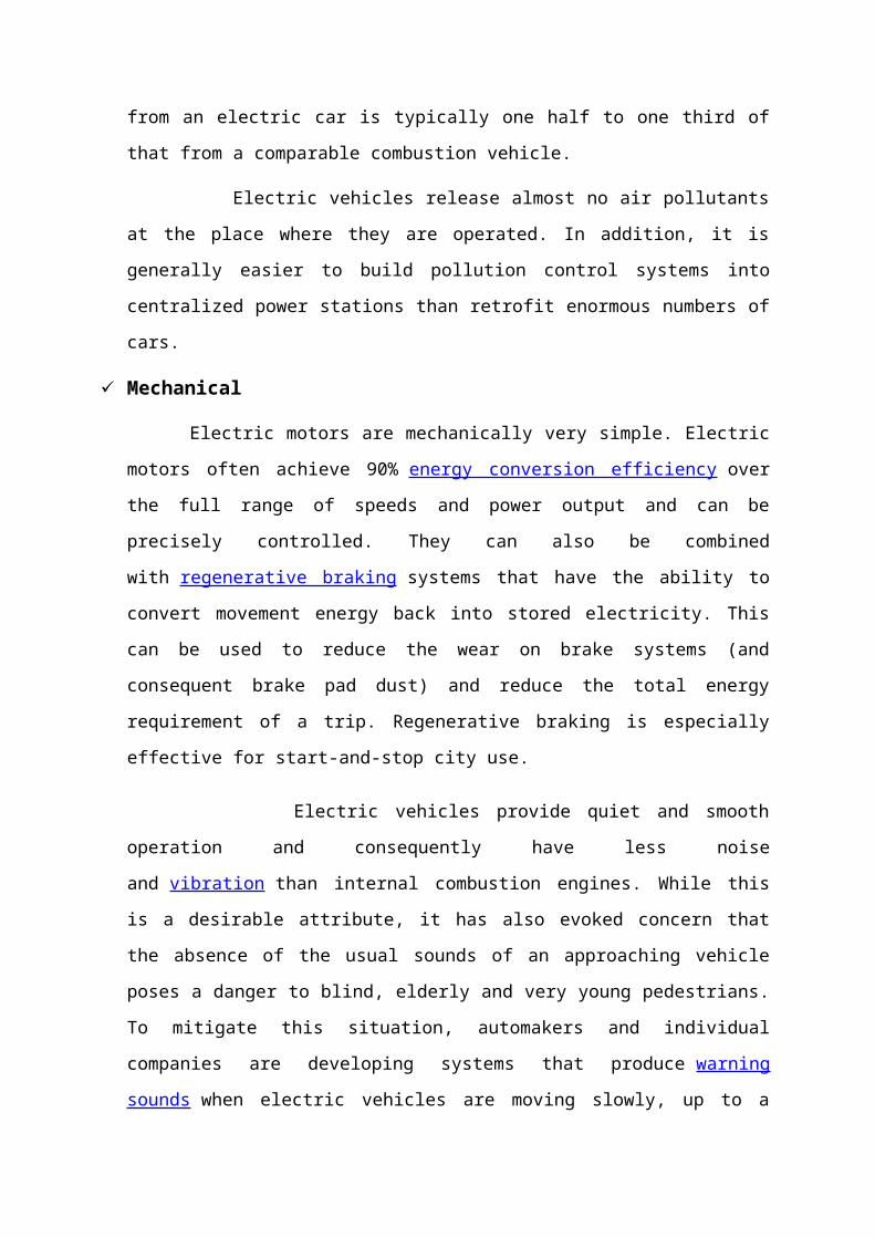
Mechanical
Electric motors are mechanically very simple. Electric motors often achieve
90% energy conversion efficiency over the full range of speeds and power output and can
be precisely controlled. They can also be combined with regenerative braking systems that
have the ability to convert movement energy back into stored electricity. This can be used
to reduce the wear on brake systems (and consequent brake pad dust) and reduce the total
energy requirement of a trip. Regenerative braking is especially effective for start-and-stop
city use.
Electric vehicles provide quiet and smooth operation and consequently have less
noise and vibration than internal combustion engines. While this is a desirable attribute, it
has also evoked concern that the absence of the usual sounds of an approaching vehicle
poses a danger to blind, elderly and very young pedestrians. To mitigate this situation,
automakers and individual companies are developing systems that produce warning
sounds when electric vehicles are moving slowly, up to a speed when normal motion and
rotation (road, suspension, electric motor, etc.) noises become audible.
Energy resilience
Electricity is a form of energy that remains within the country or region where it was
produced and can be multi-sourced. As a result it gives the greatest degree of energy
resilience.

Energy efficiency
Electric vehicle 'tank-to-wheels' efficiency is about a factor of 3 higher than internal
combustion engine vehicles. It does not consume energy when it is not moving, unlike
internal combustion engines where they continue running even during idling. However,
looking at the well-to-wheel efficiency of electric vehicles, their emissions are comparable
to an efficient gasoline or diesel in most countries because electricity generation relies on
fossil fuels.
Cost of recharge
The GM Volt will cost "less than purchasing a cup of your favorite coffee" to
recharge. The Volt should cost less than 2 cents per mile to drive on electricity, compared
with 12 cents a mile on gasoline at a price of $3.60 a gallon. This means a trip from Los
Angeles to New York would cost $56 on electricity, and $336 with gasoline. This would
be the equivalent to paying 60 cents a gallon of gas.
Stabilization of the grid
Since electric vehicles can be plugged into the electric grid when not in use, there is
a potential for battery powered vehicles to even out the demand for electricity by feeding
electricity into the grid from their batteries during peak use periods (such as mid afternoon
air conditioning use) while doing most of their charging at night, when there is unused
generating capacity. This Vehicle to Grid (V2G) connection has the potential to reduce the
need for new power plants.

5. FULL BRIDGE CONVERTER
A bridge is an arrangement of four (or more) diodes in a bridge configuration that
provides the same polarity of output for either polarity of input. When used in its most
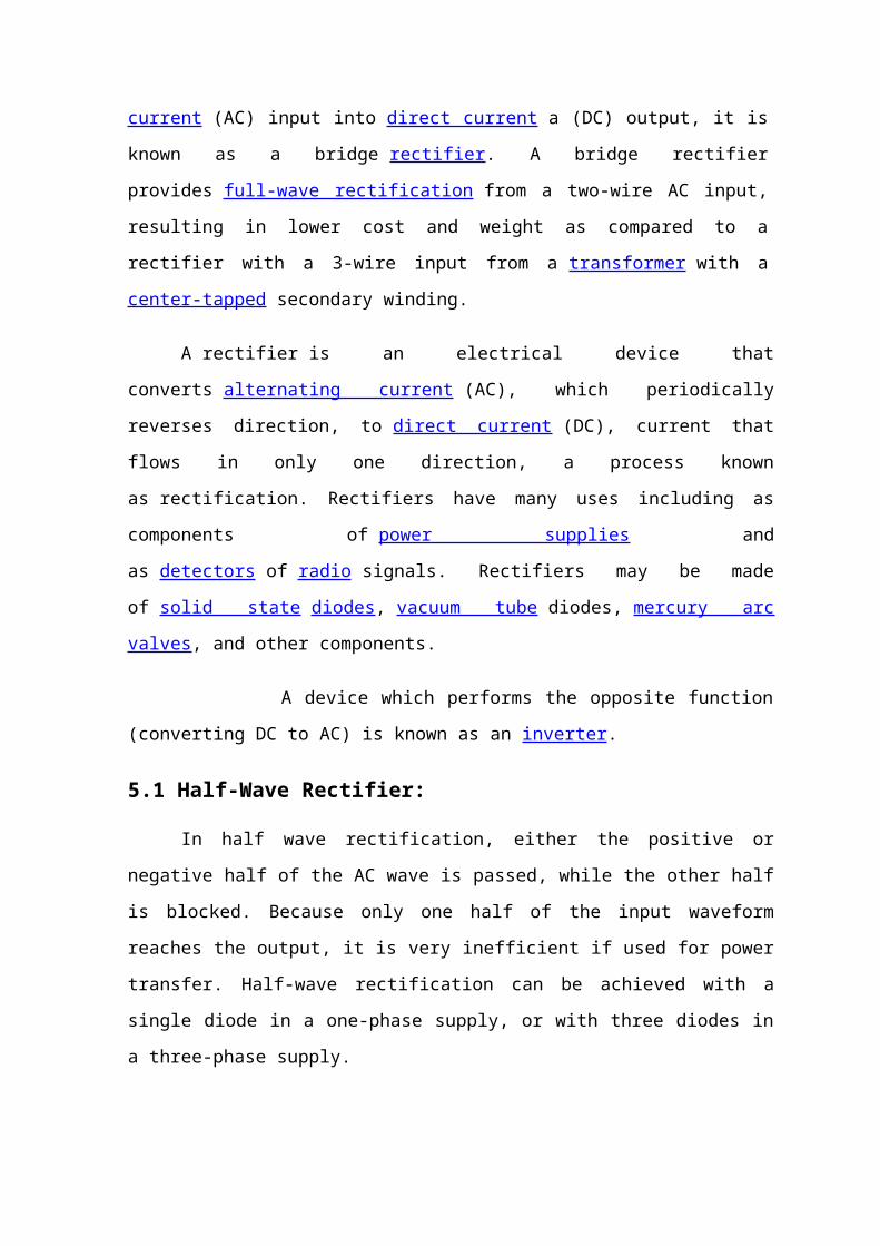
common application, for conversion of an alternating current (AC) input into direct
current a (DC) output, it is known as a bridge rectifier. A bridge rectifier provides full-
wave rectification from a two-wire AC input, resulting in lower cost and weight as
compared to a rectifier with a 3-wire input from a transformer with a center-
tapped secondary winding.
A rectifier is an electrical device that converts alternating current (AC), which
periodically reverses direction, to direct current (DC), current that flows in only one
direction, a process known as rectification. Rectifiers have many uses including as
components of power supplies and as detectors of radio signals. Rectifiers may be made
of solid state diodes, vacuum tube diodes, mercury arc valves, and other components.
A device which performs the opposite function (converting DC to AC) is known as
an inverter.
5.1 Half-Wave Rectifier:
In half wave rectification, either the positive or negative half of the AC wave is
passed, while the other half is blocked. Because only one half of the input waveform
reaches the output, it is very inefficient if used for power transfer. Half-wave rectification
can be achieved with a single diode in a one-phase supply, or with three diodes in a three-
phase supply.
Fig 5.1: Half Wave Rectifier Circuit, I/P & O/P Wave Forms

The output DC voltage of a half wave rectifier can be calculated with the following two
ideal equations:
5.2 Full-Wave Rectifier:
A full-wave rectifier converts the whole of the input waveform to one of constant
polarity (positive or negative) at its output. Full-wave rectification converts both polarities
of the input waveform to DC (direct current), and is more efficient.
However, in a circuit with a non-center tapped transformer, four diodes are required
instead of the one needed for half-wave rectification. Four diodes arranged this way are
called a diode bridge or bridge rectifier:
Fig 5.2(a): Full Wave Rectifier With Non-center Tapped Transformer
For single-phase AC, if the transformer is center-tapped, then two diodes back-to-
back (i.e. anodes-to-anode or cathode-to-cathode) can form a full-wave rectifier. Twice as
many windings are required on the transformer secondary to obtain the same output
voltage compared to the bridge rectifier above.
Fig 5.2(b): Full Wave Rectifier with Center Tapped Transformer
A very common vacuum tube rectifier configuration contained one cathode and
twin anodes inside a single envelope; in this way, the two diodes required only one
vacuum tube. The 5U4 and 5Y3 were popular examples of this configuration.

Fig5.2(c): A Three-phase Bridge Rectifier
Fig 5.2(d): 3-phase AC input, Half & Full Wave Rectified DC Output
Waveforms
For three-phase AC, six diodes are used. Typically there are three pairs of diodes,
each pair, though, is not the same kind of double diode that would be used for a full wave
single-phase rectifier. Instead the pairs are in series (anode to cathode). Typically,
commercially available double diodes have four terminals so the user can configure them
as single-phase split supply use, for half a bridge, or for three-phase.
Most devices that generate alternating current (such devices are called alternators)
generate three-phase AC. For example, an automobile alternator has six diodes inside it to
function as a full-wave rectifier for battery charging applications.
The average and root-mean-square output voltages of an ideal single phase full
wave rectifier can be calculated as:

Where:
Vdc,Vav - the average or DC output voltage,
Vp - the peak value of half wave,
Vrms - the root-mean-square value of output voltage.
π = ~ 3.14159
5.3 Peak Loss:
An aspect of most rectification is a loss from the peak input voltage to the peak
output voltage, caused by the built-in voltage drop across the diodes (around 0.7 V for
ordinary silicon p-n-junction diodes and 0.3 V for Schottky diodes). Half-wave
rectification and full-wave rectification using two separate secondaries will have a peak
voltage loss of one diode drop. Bridge rectification will have a loss of two diode drops.
This may represent significant power loss in very low voltage supplies. In addition, the
diodes will not conduct below this voltage, so the circuit is only passing current through
for a portion of each half-cycle, causing short segments of zero voltage to appear between
each "hump".
5.4 Rectifier Output Smoothing:
While half-wave and full-wave rectification suffice to deliver a form of DC output,
neither produces constant-voltage DC. In order to produce steady DC from a rectified AC
supply, a smoothing circuit or filter is required.[1] In its simplest form this can be just
a reservoir capacitor or smoothing capacitor, placed at the DC output of the rectifier.
There will still remain an amount of AC ripple voltage where the voltage is not completely
smoothed.
Fig 5.4: RC-Filter Rectifier

This circuit was designed and simulated using Multi sim 8 software.
Sizing of the capacitor represents a tradeoff. For a given load, a larger capacitor
will reduce ripple but will cost more and will create higher peak currents in the
transformer secondary and in the supply feeding it. In extreme cases where many rectifiers
are loaded onto a power distribution circuit, it may prove difficult for the power
distribution authority to maintain a correctly shaped sinusoidal voltage curve.
For a given tolerable ripple the required capacitor size is proportional to the load
current and inversely proportional to the supply frequency and the number of output peaks
of the rectifier per input cycle. The load current and the supply frequency are generally
outside the control of the designer of the rectifier system but the number of peaks per input
cycle can be affected by the choice of rectifier design.
A half-wave rectifier will only give one peak per cycle and for this and other
reasons is only used in very small power supplies. A full wave rectifier achieves two peaks
per cycle and this is the best that can be done with single-phase input. For three-phase
inputs a three-phase bridge will give six peaks per cycle and even higher numbers of peaks
can be achieved by using transformer networks placed before the rectifier to convert to a
higher phase order.
To further reduce this ripple, a capacitor-input filter can be used. This
complements the reservoir capacitor with a choke (inductor) and a second filter capacitor,
so that a steadier DC output can be obtained across the terminals of the filter capacitor.
The choke presents a high impedance to the ripple current.
5.5 Voltage Doubling Rectifier:
The simple half wave rectifier can be built in two versions with the diode pointing
in opposite directions, one version connects the negative terminal of the output direct to
the AC supply and the other connects the positive terminal of the output direct to the AC
supply. By combining both of these with separate output smoothing it is possible to get an
output voltage of nearly double the peak AC input voltage. This also provides a tap in the
middle, which allows use of such a circuit as a split rail supply.

A variant of this is to use two capacitors in series for the output smoothing on a
bridge rectifier then place a switch between the midpoint of those capacitors and one of
the AC input terminals. With the switch open this circuit will act like a normal bridge
rectifier with it closed it will act like a voltage doubling rectifier. In other words this
makes it easy to derive a voltage of roughly 320V (+/- around 15%) DC from any mains
supply in the world, this can then be fed into a relatively simple switched mode power
supply.
Fig 5.5: Cockcroft Walton Voltage Multiplier
Cascaded stages of diodes and capacitors can be added to make a voltage
multiplier (Cockroft-Walton circuit). These circuits can provide a potential several times
that of the peak value of the input AC, although limited in current output and regulation.
Voltage multipliers are used to provide the high voltage for a CRT in a television receiver,
or for powering high-voltage tubes such as image intensifiers or photo multipliers.
The essential feature of a diode bridge is that the polarity of the output is the same
regardless of the polarity at the input. The diode bridge circuit is also known as the Graetz
circuit after its inventor, physicist Leo Graetz.
5.6 Basic Operation:
According to the conventional model of current flow originally established
by Benjamin Franklin and still followed by most engineers today, current is assumed to
flow through electrical conductors from the positive to the negative pole. In actuality, free
electrons in a conductor nearly always flow from the negative to the positive pole. In the
vast majority of applications, however, the actual direction of current flow is irrelevant.
Therefore, in the discussion below the conventional model is retained.

Fig 5.6(a): AC, Half-wave and Full Wave Rectified Signals
In each case, the upper right output remains positive and lower right output
negative. Since this is true whether the input is AC or DC, this circuit not only produces a
DC output from an AC input, it can also provide what is sometimes called "reverse
polarity protection". That is, it permits normal functioning of DC-powered equipment
when batteries have been installed backwards, or when the leads (wires) from a DC power
source have been reversed, and protects the equipment from potential damage caused by
reverse polarity.
5.7 Output Smoothing:
For many applications, especially with single phase AC where the full-wave
bridge serves to convert an AC input into a DC output, the addition of a capacitor may be
desired because the bridge alone supplies an output of fixed polarity but continuously
varying or "pulsating" magnitude, an attribute commonly referred to as "ripple" (see
diagram to right).
The function of this capacitor, known as a reservoir capacitor (or smoothing
capacitor) is to lessen the variation in (or 'smooth') the rectified AC output voltage
waveform from the bridge. One explanation of 'smoothing' is that the capacitor provides a
low impedance path to the AC component of the output, reducing the AC voltage across,
and AC current through, the resistive load. In less technical terms, any drop in the output
voltage and current of the bridge tends to be canceled by loss of charge in the capacitor.
This charge flows out as additional current through the load. Thus the change of load

current and voltage is reduced relative to what would occur without the capacitor.
Increases of voltage correspondingly store excess charge in the capacitor, thus moderating
the change in output voltage / current.
The capacitor and the load resistance have a typical time constant τ =
RC where C and R are the capacitance and load resistance respectively. As long as the load
resistor is large enough so that this time constant is much longer than the time of one
ripple cycle, the above configuration will produce a smoothed DC voltage across the load.
In some designs, a series resistor at the load side of the capacitor is added. The
smoothing can then be improved by adding additional stages of capacitor–resistor pairs,
often done only for sub-supplies to critical high-gain circuits that tend to be sensitive to
supply voltage noise.
In a practical circuit, when a capacitor is directly connected to the output of a
bridge, the bridge diodes must be sized to withstand the current surge that occurs when the
power is turned on at the peak of the AC voltage and the capacitor is fully discharged.
Sometimes a small series resistor is included before the capacitor to limit this current,
though in most applications the power supply transformer's resistance is already sufficient.
Output can also be smoothed using a choke and second capacitor. The choke tends
to keep the current (rather than the voltage) more constant. This design is not generally
used in modern equipment due to the high cost of an effective choke compared to a
resistor and capacitor.
Some early console radios created the speaker's constant field with the current
from the high voltage ("B +") power supply, which was then routed to the consuming
circuits, (permanent magnets were then too weak for good performance) to create the
speaker's constant magnetic field. The speaker field coil thus performed 2 jobs in one: it
acted as a choke, filtering the power supply, and it produced the magnetic field to operate
the speaker.

Poly-phase Bridge:
The diode bridge can be generalized to rectify poly-phase AC inputs. For example, for
a three-phase AC input, a half-wave rectifier consists of three diodes, but a full-
wave bridge rectifier consists of six diodes.
Fig 5.7(a): Three Phase Bridge Rectifier
Fig 5.7(b): 3-phase AC Input Waveform, Half-wave Rectified Waveform, and Full-
wave Rectified Waveform
6. POWER MANAGEMENT
Power management is a feature of some electrical appliances,
especially copiers, computers and computer peripherals such as monitors and printers, that
turns off the power or switches the system to a low-power state when inactive. In
computing this is known as PC power management and is built around a standard
called ACPI. This supersedes APM. All recent (consumer) computers have ACPI support.
Motivation:
PC power management for computer systems is desired for many reasons, particularly:
Reduce overall energy consumption
Prolong battery life for portable and embedded systems
Reduce cooling requirements
Reduce noise
Reduce operating costs for energy and cooling.
Lower power consumption also means lower heat dissipation, which increases
system stability, and less energy use, which saves money and reduces the impact on the
environment.
Processor level techniques:
The power management for microprocessors can be done over the whole processor,
or in specific areas.
With dynamic voltage scaling and dynamic frequency scaling, the CPU core
voltage, clock rate, or both, can be altered to decrease power consumption at the price of
potentially lower performance. This is sometimes done in real time to optimize the power-
performance tradeoff.
Examples:
AMD Cool'n'Quiet
AMD PowerNow! [1]
IBM EnergyScale [2]

Additionally, processors can selectively power off internal circuitry (power gating). For
example:
Newer Intel Core processors support ultra-fine power control over the functional units
within the processors.
AMD Cool Core technology get more efficient performance by dynamically activating or
turning off parts of the processor.[3]
Intel VRT technology split the chip into a 3.3V I/O section and a 2.9V core section. The
lower core voltage reduces power consumption.
6.1 Power Management System Helps To:
Avoid Black-outs
In case of a lack of power, Load Shedding secures the electrical power to critical loads by
switching off non-critical loads according to dynamic priority tables.
Reduce Energy Costs / Peak Shaving
When all on-site power generation is maximized and the power demand still tends to
exceed the contracted maximum electricity import, the system will automatically shed
some of the low priority loads.
Enhanced Operator Support
At sites where electricity is produced by several generators, the demands with respect to
control activities by operators are much higher. Advanced functions such as intelligent
alarm filtering, consistency analysis, operator guidance, and a well organized single-
window interface support the operator and prevent incorrect interventions.
Achieve Stable Operation
The Power Control function shares the active and reactive power between the different
generators and tie-lines in such a way that the working points of the machines are as far as
possible away from the border of the individual PQ-capability diagrams so that the plant
can withstand bigger disturbances.
Optimize Network Design

Because the set points for the generators, turbines and transformers are calculated in such
a way that no component will be overloaded and the electrical network can be used up to
its limits, over-dimensioning of the network is no longer needed.
Minimize Cabling and Engineering
All the signals and information which are available in protection/control relays,
governor/excitation controllers and other microprocessor based equipment can be easily
transmitted to the Industrial PMS via serial communication links. This avoids marshalling
cubicles, interposing relays, cable ducts, spaghetti wiring, cabling engineering and
provides extra functionality such as parameter setting/reading, stored events, disturbance
data analysis and a single window to all electrical related data.
7. DC/DC CONVERTERS TOPOLOGIES AND
MODELING
7.1. Multi Boost and Multi Full Bridge Converters Modeling:
• Figure 7.1(a)(a,b) shows the multi boost converter topology.
Fig 7.1(a): (a) Multi boost Converter Topology & (b) Multi Full Bridge Converter
Topology
The general model for this topology is given by equation; where (α1) and (n) define
respectively the duty cycle and parallel input converter number.
The voltage drops in the Ln and λ inductances are given by equation.

The converter average model has a nonlinear behavior because of crosses between
α1 control variable and Vbus1 parameter. The Vbus1, Vsc1, Vsc2, Vscn , Ich and Vbat
variables can to disturb the control, they must be measured and used in the estimate of the
control law to ensure a dynamics of control [3]. The multi boost converter [4] topology
control law which results from the boost converter modeling is presented by α1 duty cycle;
where Np = max(n) is the maximum number of parallel converters.
The multi boost converter control strategy is presented in Fig 7.1(b) (a).
Fig 7.1(b): (a) Multi Boost Control Strategy & (b) Multi Full Bridge Control
Strategy
It ensures the super capacitor modules discharge with variable current. The super
capacitors reference current (Iscref) is obtained starting from the power management
between batteries and hybrid vehicle DC-link. This control strategy includes the super
capacitors and batteries current control loops. PWM1 signal ensures the multi boost
converters control during super capacitor modules discharge. These modules being
identical, the energy management between the modules and the hybrid vehicle DC-link
enables to write the super capacitors current references.

To simplify the super capacitors current references estimation, the multi boost converter
efficiency (η) was fixed at 85%.
The multi full bridge converter control strategy proposed in this paper consists to establish
the full bridge converters standardized voltage. The control law which result from the
multi full bridge converter modeling is presented by equation, where (m) defines the
transformer turns ratio.
This standardized voltage is compared with two triangular carrier waves of
amplitude Vmax = 1V with a switching frequency of 20 kHz. The inverter control strategy
is presented in Fig.(b); where Q1, Q2, Q3 and Q4 are the control signals applied to K1,
K2, K3 and K4 switches. The simulations and experimental parameters are presented in
table 1 below.
7.2 Full Bridge Converter Simulation Results For Np = 2:
The simulation has been made for Np = 2. The maximum and minimum voltages
of the super capacitor modules are respectively fixed at 270V and 135V. The hybrid
vehicle requested current (Ich) is respectively fixed at 100A from 0 to 0.5s, 400A from
0.5s to 18s and 100A from 18s to 20s. Battery reference current (Ibatref) is fixed at 100A
independently of the hybrid vehicle power request.
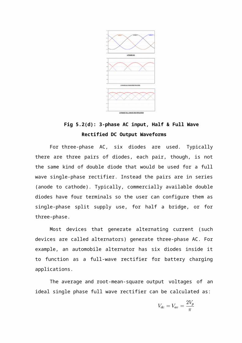
Fig 7.2(a): (a) Super Capacitor Modules Voltages, (b) Super Capacitor Modules
Currents
(a) (b)
Fig 7.2(b) (a): Battery current control result, (b): DC-link and active load currents
Super capacitor modules voltages (Vsc1, Vsc2) presented in Fig 7.2(a) (a) are
identical. The currents amplitudes (Isc1, Isc2) presented in Fig 7.2(a) (b) are also identical.
Control enables to maintain the battery current (Ibat) at 100A; but around 0.5s and 18s the
battery current control loop has not enough time to react Fig 7.2 (b) (a). The important
power of the transient states is ensured by the super capacitors modules (IL) Fig 7.2(b) (b).
Simulation parameters are presented in TABLE 1.
TABLE 1: FULL BRIDGE TOPOLOGIE SIMULATIONS PARAMETER

8. SIMULINK DIAGRAM
8 (a): Boost converter circuit
8 (b): Full bridge converter circuit


9. DESIGN AND EXPERIMENTAL RESULTS
Wiring in power electronic design is a general problem for electrical energy system
and the voltage inverters do not escape to this problem. The switch action of
semiconductors causes instantaneous fluctuations of the current and any stray inductance
in the commutation cell will produce high voltage variations. Semiconductors, when
switching off, leads to high voltage transitions which is necessary to control within
tolerable limits. The energy stored in parasitic inductances, during switching on, is
generally dissipated by this semiconductor.
In the case of the single-phase inverter, each cell includes two switches and a
decoupling capacitor placed at the cell boundaries, which presents a double role. It enables
to create an instantaneous voltage source very close to the inverter. The (C) capacitor
associated to an inductor enables to filter the harmonic components of the currents which
are generated by the inverter. Parasitic inductances staying in the mesh include the
capacitor inductance, the internal inductance of semiconductors and the electric
connection inductances. A good choice of the components with an optimal wiring enables
to minimize parasitic inductances. Using the semiconductors modules solves the
connection problems between components. All these efforts can become insufficient, if
residual inductances remain too high or if the inverter type is the low voltages and strong
currents for which the voltage variations are much important. In both cases, the use of the
chopping devices is necessary. These devices must be placed very close to the component
to avoid any previous problem. The parameters used for experimental tests are presented
in TABLE 2 and the principle of such circuits is given in Fig 9.
TABLE 2: FULL BRIDGE EXPERIMENTAL PARAMETERS

Fig 9: Full Bridge Converter With Chopping Devices
During switching off of the semiconductors, the corresponding current stored in
wiring inductances circulates in the following meshes C1, D1 ; C2 , D2; C3, D3 and C4 ,
D4 which limits the voltages applied to the switches. When electrical energy is fully
transferred in C1, C2, C3 and C4 capacitors, the current becomes null and the meshes
become closed. The C1, C2, C3 and C4 capacitors are used only for transient energy tank
and it is necessary to recycle this switching energy while controlling the voltage at the
semiconductors boundary. This function is ensured by R1, R2, R3 and R4 resistances. R1,
R2, R3 and R4 resistances are identical and C1, C2, C3 and C4 capacitors are also
identical.
9.1 Experimental Setup at Reduced Scale
For reasons of cost components and safety, the experimental test benches were carried
out at a reduced scale (1/10).
• The boost converter test bench Fig (a) is made of: a battery module of 4 cells in series,
two super capacitors modules of 10 cells (Maxwell BOOSTCAP2600) in series for each
one, an active load which is used to define power request, two boost converters in parallel
which ensure power management in hybrid vehicle.
• For the full bridge converter [9] test bench Fig (b), a batteries module, a super capacitors
module, two high frequency planar transformer, the DC/AC and AC/DC converters have
been designed. The super capacitors modules voltages must be between 27 V and 13.5 V.

Fig 9.1: Boost and Full Bridge Converters Experimental Setup
The batteries module which imposes the DC-bus voltage presents a rated voltage
of 48 V and the DC-link voltage level must be between 43 V and 60 V. The converters are
controlled by a PIC18F4431 microcontroller with 10 kHz control frequencies for boost
converters and 20 kHz for the full bridge converter.
9.2. Boost Converters Simulation and Experimental Results
The boost converters experimental test is carried out in the following conditions:
During the super capacitors discharge, the batteries current reference (Ibatref) is fixed at
13A so that, the super capacitors modules provide hybrid vehicle power request during the
transient states. For these tests, the hybrid vehicle request (Ich) was fixed at 53A. The
experimental and simulations results of the modules voltage are compared in Fig (a) and
Fig (b). The (Isc1) and (Isc2) experimental currents are not identical
Fig 9.2(a): Super Capacitor Modules Experimental and Simulation Voltage Results

Fig (a), Fig (b) because the super capacitors dispersion and the power electronic circuits
(boost converters) inequality.
Fig 9.2(b): Super Capacitor Modules Experimental and Simulation Current Results
The first boost converter ensures 50% and the second ensures also 50% of the DC-
link current(IL). In other words the two super capacitors modules ensure a (IL) current of
40A to hybrid
vehicle as presented in Fig (a), and 13A only is provided by the batteries Fig (b).
Fig 9.2(c): DC-link voltage and current experimental validation

CONCLUSION
In this project, multi boost and multi full bridge converter topologies and their
control strategies for batteries and super capacitors coupling in the hybrid vehicle
applications were proposed. The system control is ensured by PIC18F4431
microcontroller type which includes 9 analog inputs and 8 PWM outputs. For reasons of
simplicity and cost, the multi boost converter is the most interesting topology regarding
the multi full bridge converter topology. It enables a good power management in hybrid
vehicle. Full bridge experimental tests conditions were different from that of boost
converter topology, so at this time it is not easy to make a good comparison between the
two topologies. However, multi full bridge converter topology is well suitable to adapt the
level of available voltage to the DC-link. For low voltage and high current applications
such as super capacitors, the full bridge converter seems to be less interesting because of
its higher cost (many silicon and passive components), and a lower efficiency.
REFERENCES
[1] J.M Timmermans, P. Zadora, J. Cheng, Y. Van Mierlo, and Ph. Lataire. Modelling and
design of super capacitors as peak power unit for hybrid electric vehicles. Vehicle Power
and Propulsion, IEEE Conference, 7-9 September, page 8pp, 2005.
[2] Huang jen Chiu, Hsiu Ming Li-Wei Lin, and Ming-Hsiang Tseng. A multiple- input
dc/dc converter for renewable energy systems. ICIT2005, IEEE, 14-17 December, pages
1304–1308, 2005.
[3] M.B. Camara, H. Gualous, F. Gustin, and A. Berthon. Control strategy of hybrid
sources for transport applications using supercapacitors and batteries. IPEMC2006, 13-16
August, Shanghai, P.R.CHINA, 1:1–5, 2006.
[4] L. Solero, A. Lidozzi, and J.A. Pomilo. Design of multiple-input power converter for
hybrid vehicles. IEEE transactions on power electronics, 20, Issue 5, 2005.
[5] Xin KONG and A. KHA. Analysis and implementation of a high efficiency,
interleaved current-fed full bridge converter for fuel cell system. IEEE, 28-01 Nov, 1:474–
479, 2005.
[6] M.B. Camara, F. Gustin, H. Gualous and A. Berthon. Studies and realization of the
buck-boost and full bridge converters with multi sources system for the hybrid vehicle
applications. Second European Symposium on Super capacitors and Applications,
ESSCAP2006, Lausanne, Switzerland,2-3 November, 2006.
[7] Huang-Jen Chiu, Hsiu-Ming, Li-Wei Lin, Ming-Hsiang Tseng. A Multiple-Input
DC/DC Converter for Renewable Energy Systems, Industrial Technology, ICIT2005,
IEEE international Conference, 14-17 December 2005, Pages:1304-1308