subpart l—scaffolds - gpo · subpart l—scaffolds authority: section 107, contract work ......
TRANSCRIPT

281
Occupational Safety and Health Admin., Labor § 1926.450
(d) Motor-circuit switch. A switch, rated in horsepower, capable of inter-rupting the maximum operating over-load current of a motor of the same horsepower rating as the switch at the rated voltage.
Switching devices. (Over 600 volts, nominal.) Devices designed to close and/or open one or more electric cir-cuits. Included in this category are cir-cuit breakers, cutouts, disconnecting (or isolating) switches, disconnecting means, and interrupter switches.
Transportable X-ray. X-ray equipment installed in a vehicle or that may read-ily be disassembled for transport in a vehicle.
Utilization equipment. Utilization equipment means equipment which uti-lizes electric energy for mechanical, chemical, heating, lighting, or similar useful purpose.
Utilization system. A utilization sys-tem is a system which provides electric power and light for employee work-places, and includes the premises wir-ing system and utilization equipment.
Ventilated. Provided with a means to permit circulation of air sufficient to remove an excess of heat, fumes, or va-pors.
Volatile flammable liquid. A flammable liquid having a flash point below 38 de-grees C (100 degrees F) or whose tem-perature is above its flash point, or a Class II combustible liquid having a vapor pressure not exceeding 40 psia (276 kPa) at 38 °C (100 °F) whose tem-perature is above its flash point.
Voltage. (Of a circuit.) The greatest root-mean-square (effective) difference of potential between any two conduc-tors of the circuit concerned.
Voltage, nominal. A nominal value as-signed to a circuit or system for the purpose of conveniently designating its voltage class (as 120/240, 480Y/277, 600, etc.). The actual voltage at which a cir-cuit operates can vary from the nomi-nal within a range that permits satis-factory operation of equipment.
Voltage to ground. For grounded cir-cuits, the voltage between the given conductor and that point or conductor of the circuit that is grounded; for ungrounded circuits, the greatest volt-age between the given conductor and any other conductor of the circuit.
Watertight. So constructed that mois-ture will not enter the enclosure.
Weatherproof. So constructed or pro-tected that exposure to the weather will not interfere with successful oper-ation. Rainproof, raintight, or water-tight equipment can fulfill the require-ments for weatherproof where varying weather conditions other than wetness, such as snow, ice, dust, or temperature extremes, are not a factor.
Wet location. See ‘‘Location.’’
Subpart L—Scaffolds
AUTHORITY: Section 107, Contract Work Hours and Safety Standards Act (Construc-tion Safety Act)(40 U.S.C. 333); Secs. 4, 6, 8, Occupational Safety and Health Act of 1970 (29 U.S.C. 653, 655, 657); Secretary of Labor’s Order Nos. 1–90 (55 FR 9033) and 5–2007 (72 FR 31159); and 29 CFR part 1911.
SOURCE: 61 FR 46104, Aug. 30, 1996, unless otherwise noted.
§ 1926.450 Scope, application and defi-nitions applicable to this subpart.
(a) Scope and application. This sub-part applies to all scaffolds used in workplaces covered by this part. It does not apply to crane or derrick sus-pended personnel platforms. The cri-teria for aerial lifts are set out exclu-sively in § 1926.453.
(b) Definitions. Adjustable suspension scaffold means a suspension scaffold equipped with a hoist(s) that can be op-erated by an employee(s) on the scaf-fold.
Bearer (putlog) means a horizontal transverse scaffold member (which may be supported by ledgers or run-ners) upon which the scaffold platform rests and which joins scaffold uprights, posts, poles, and similar members.
Boatswains’ chair means a single- point adjustable suspension scaffold consisting of a seat or sling designed to support one employee in a sitting posi-tion.
Body belt (safety belt) means a strap with means both for securing it about the waist and for attaching it to a lan-yard, lifeline, or deceleration device.
Body harness means a design of straps which may be secured about the em-ployee in a manner to distribute the fall arrest forces over at least the
VerDate Mar<15>2010 15:51 Sep 16, 2011 Jkt 223116 PO 00000 Frm 00291 Fmt 8010 Sfmt 8010 Q:\29\29V8.TXT ofr150 PsN: PC150
282
29 CFR Ch. XVII (7–1–11 Edition) § 1926.450
thighs, pelvis, waist, chest and shoul-ders, with means for attaching it to other components of a personal fall ar-rest system.
Brace means a rigid connection that holds one scaffold member in a fixed position with respect to another mem-ber, or to a building or structure.
Bricklayers’ square scaffold means a supported scaffold composed of framed squares which support a platform.
Carpenters’ bracket scaffold means a supported scaffold consisting of a plat-form supported by brackets attached to building or structural walls.
Catenary scaffold means a suspension scaffold consisting of a platform sup-ported by two essentially horizontal and parallel ropes attached to struc-tural members of a building or other structure. Additional support may be provided by vertical pickups.
Chimney hoist means a multi-point adjustable suspension scaffold used to provide access to work inside chim-neys. (See ‘‘Multi-point adjustable sus-pension scaffold’’.)
Cleat means a structural block used at the end of a platform to prevent the platform from slipping off its supports. Cleats are also used to provide footing on sloped surfaces such as crawling boards.
Competent person means one who is capable of identifying existing and pre-dictable hazards in the surroundings or working conditions which are unsani-tary, hazardous, or dangerous to em-ployees, and who has authorization to take prompt corrective measures to eliminate them.
Continuous run scaffold (Run scaffold) means a two- point or multi-point ad-justable suspension scaffold con-structed using a series of inter-connected braced scaffold members or supporting structures erected to form a continuous scaffold.
Coupler means a device for locking together the tubes of a tube and cou-pler scaffold.
Crawling board (chicken ladder) means a supported scaffold consisting of a plank with cleats spaced and secured to provide footing, for use on sloped sur-faces such as roofs.
Deceleration device means any mecha-nism, such as a rope grab, rip-stitch lanyard, specially-woven lanyard, tear-
ing or deforming lanyard, or automatic self-retracting lifeline lanyard, which dissipates a substantial amount of en-ergy during a fall arrest or limits the energy imposed on an employee during fall arrest.
Double pole (independent pole) scaffold means a supported scaffold consisting of a platform(s) resting on cross beams (bearers) supported by ledgers and a double row of uprights independent of support (except ties, guys, braces) from any structure.
Equivalent means alternative designs, materials or methods to protect against a hazard which the employer can demonstrate will provide an equal or greater degree of safety for employ-ees than the methods, materials or de-signs specified in the standard.
Exposed power lines means electrical power lines which are accessible to em-ployees and which are not shielded from contact. Such lines do not include extension cords or power tool cords.
Eye or Eye splice means a loop with or without a thimble at the end of a wire rope.
Fabricated decking and planking means manufactured platforms made of wood (including laminated wood, and solid sawn wood planks), metal or other materials.
Fabricated frame scaffold (tubular welded frame scaffold) means a scaffold consisting of a platform(s) supported on fabricated end frames with integral posts, horizontal bearers, and inter-mediate members.
Failure means load refusal, breakage, or separation of component parts. Load refusal is the point where the ultimate strength is exceeded.
Float (ship) scaffold means a suspen-sion scaffold consisting of a braced platform resting on two parallel bear-ers and hung from overhead supports by ropes of fixed length.
Form scaffold means a supported scaf-fold consisting of a platform supported by brackets attached to formwork.
Guardrail system means a vertical bar-rier, consisting of, but not limited to, toprails, midrails, and posts, erected to prevent employees from falling off a scaffold platform or walkway to lower levels.
VerDate Mar<15>2010 15:51 Sep 16, 2011 Jkt 223116 PO 00000 Frm 00292 Fmt 8010 Sfmt 8010 Q:\29\29V8.TXT ofr150 PsN: PC150
283
Occupational Safety and Health Admin., Labor § 1926.450
Hoist means a manual or power-oper-ated mechanical device to raise or lower a suspended scaffold.
Horse scaffold means a supported scaf-fold consisting of a platform supported by construction horses (saw horses). Horse scaffolds constructed of metal are sometimes known as trestle scaf-folds.
Independent pole scaffold (see ‘‘Double pole scaffold’’).
Interior hung scaffold means a suspen-sion scaffold consisting of a platform suspended from the ceiling or roof structure by fixed length supports.
Ladder jack scaffold means a sup-ported scaffold consisting of a platform resting on brackets attached to lad-ders.
Ladder stand means a mobile, fixed- size, self-supporting ladder consisting of a wide flat tread ladder in the form of stairs.
Landing means a platform at the end of a flight of stairs.
Large area scaffold means a pole scaf-fold, tube and coupler scaffold, systems scaffold, or fabricated frame scaffold erected over substantially the entire work area. For example: a scaffold erected over the entire floor area of a room.
Lean-to scaffold means a supported scaffold which is kept erect by tilting it toward and resting it against a building or structure.
Lifeline means a component con-sisting of a flexible line that connects to an anchorage at one end to hang vertically (vertical lifeline), or that connects to anchorages at both ends to stretch horizontally (horizontal life-line), and which serves as a means for connecting other components of a per-sonal fall arrest system to the anchor-age.
Lower levels means areas below the level where the employee is located and to which an employee can fall. Such areas include, but are not limited to, ground levels, floors, roofs, ramps, runways, excavations, pits, tanks, ma-terials, water, and equipment.
Masons’ adjustable supported scaffold (see ‘‘Self-contained adjustable scaf-fold’’).
Masons’ multi-point adjustable suspen-sion scaffold means a continuous run
suspension scaffold designed and used for masonry operations.
Maximum intended load means the total load of all persons, equipment, tools, materials, transmitted loads, and other loads reasonably anticipated to be applied to a scaffold or scaffold component at any one time.
Mobile scaffold means a powered or unpowered, portable, caster or wheel- mounted supported scaffold.
Multi-level suspended scaffold means a two-point or multi-point adjustable suspension scaffold with a series of platforms at various levels resting on common stirrups.
Multi-point adjustable suspension scaf-fold means a suspension scaffold con-sisting of a platform(s) which is sus-pended by more than two ropes from overhead supports and equipped with means to raise and lower the platform to desired work levels. Such scaffolds include chimney hoists.
Needle beam scaffold means a platform suspended from needle beams.
Open sides and ends means the edges of a platform that are more than 14 inches (36 cm) away horizontally from a sturdy, continuous, vertical surface (such as a building wall) or a sturdy, continuous horizontal surface (such as a floor), or a point of access. Exception: For plastering and lathing operations the horizontal threshold distance is 18 inches (46 cm).
Outrigger means the structural mem-ber of a supported scaffold used to in-crease the base width of a scaffold in order to provide support for and in-creased stability of the scaffold.
Outrigger beam (Thrustout) means the structural member of a suspension scaffold or outrigger scaffold which provides support for the scaffold by ex-tending the scaffold point of attach-ment to a point out and away from the structure or building.
Outrigger scaffold means a supported scaffold consisting of a platform rest-ing on outrigger beams (thrustouts) projecting beyond the wall or face of the building or structure, the inboard ends of which are secured inside the building or structure.
Overhand bricklaying means the proc-ess of laying bricks and masonry units such that the surface of the wall to be jointed is on the opposite side of the
VerDate Mar<15>2010 15:51 Sep 16, 2011 Jkt 223116 PO 00000 Frm 00293 Fmt 8010 Sfmt 8010 Q:\29\29V8.TXT ofr150 PsN: PC150
284
29 CFR Ch. XVII (7–1–11 Edition) § 1926.450
wall from the mason, requiring the mason to lean over the wall to com-plete the work. It includes mason tend-ing and electrical installation incor-porated into the brick wall during the overhand bricklaying process.
Personal fall arrest system means a system used to arrest an employee’s fall. It consists of an anchorage, con-nectors, a body belt or body harness and may include a lanyard, decelera-tion device, lifeline, or combinations of these.
Platform means a work surface ele-vated above lower levels. Platforms can be constructed using individual wood planks, fabricated planks, fab-ricated decks, and fabricated plat-forms.
Pole scaffold (see definitions for ‘‘Single-pole scaffold’’ and ‘‘Double (independent) pole scaffold’’).
Power operated hoist means a hoist which is powered by other than human energy.
Pump jack scaffold means a supported scaffold consisting of a platform sup-ported by vertical poles and movable support brackets.
Qualified means one who, by posses-sion of a recognized degree, certificate, or professional standing, or who by ex-tensive knowledge, training, and expe-rience, has successfully demonstrated his/her ability to solve or resolve prob-lems related to the subject matter, the work, or the project.
Rated load means the manufacturer’s specified maximum load to be lifted by a hoist or to be applied to a scaffold or scaffold component.
Repair bracket scaffold means a sup-ported scaffold consisting of a platform supported by brackets which are se-cured in place around the circum-ference or perimeter of a chimney, stack, tank or other supporting struc-ture by one or more wire ropes placed around the supporting structure.
Roof bracket scaffold means a rooftop supported scaffold consisting of a plat-form resting on angular-shaped sup-ports.
Runner (ledger or ribbon) means the lengthwise horizontal spacing or brac-ing member which may support the bearers.
Scaffold means any temporary ele-vated platform (supported or sus-
pended) and its supporting structure (including points of anchorage), used for supporting employees or materials or both.
Self-contained adjustable scaffold means a combination supported and suspension scaffold consisting of an ad-justable platform(s) mounted on an independent supporting frame(s) not a part of the object being worked on, and which is equipped with a means to per-mit the raising and lowering of the platform(s). Such systems include roll-ing roof rigs, rolling outrigger systems, and some masons’ adjustable supported scaffolds.
Shore scaffold means a supported scaf-fold which is placed against a building or structure and held in place with props.
Single-point adjustable suspension scaf-fold means a suspension scaffold con-sisting of a platform suspended by one rope from an overhead support and equipped with means to permit the movement of the platform to desired work levels.
Single-pole scaffold means a supported scaffold consisting of a platform(s) resting on bearers, the outside ends of which are supported on runners secured to a single row of posts or uprights, and the inner ends of which are supported on or in a structure or building wall.
Stair tower (Scaffold stairway/tower) means a tower comprised of scaffold components and which contains inter-nal stairway units and rest platforms. These towers are used to provide access to scaffold platforms and other ele-vated points such as floors and roofs.
Stall load means the load at which the prime-mover of a power-operated hoist stalls or the power to the prime- mover is automatically disconnected.
Step, platform, and trestle ladder scaf-fold means a platform resting directly on the rungs of step ladders or trestle ladders.
Stilts means a pair of poles or similar supports with raised footrests, used to permit walking above the ground or working surface.
Stonesetters’ multi-point adjustable sus-pension scaffold means a continuous run suspension scaffold designed and used for stonesetters’ operations.
Supported scaffold means one or more platforms supported by outrigger
VerDate Mar<15>2010 15:51 Sep 16, 2011 Jkt 223116 PO 00000 Frm 00294 Fmt 8010 Sfmt 8010 Q:\29\29V8.TXT ofr150 PsN: PC150
285
Occupational Safety and Health Admin., Labor § 1926.451
beams, brackets, poles, legs, uprights, posts, frames, or similar rigid support.
Suspension scaffold means one or more platforms suspended by ropes or other non-rigid means from an over-head structure(s).
System scaffold means a scaffold con-sisting of posts with fixed connection points that accept runners, bearers, and diagonals that can be inter-connected at predetermined levels.
Tank builders’ scaffold means a sup-ported scaffold consisting of a platform resting on brackets that are either di-rectly attached to a cylindrical tank or attached to devices that are attached to such a tank.
Top plate bracket scaffold means a scaffold supported by brackets that hook over or are attached to the top of a wall. This type of scaffold is similar to carpenters’ bracket scaffolds and form scaffolds and is used in residen-tial construction for setting trusses.
Tube and coupler scaffold means a sup-ported or suspended scaffold consisting of a platform(s) supported by tubing, erected with coupling devices con-necting uprights, braces, bearers, and runners.
Tubular welded frame scaffold (see ‘‘Fabricated frame scaffold’’).
Two-point suspension scaffold (swing stage) means a suspension scaffold con-sisting of a platform supported by hangers (stirrups) suspended by two ropes from overhead supports and equipped with means to permit the raising and lowering of the platform to desired work levels.
Unstable objects means items whose strength, configuration, or lack of sta-bility may allow them to become dis-located and shift and therefore may not properly support the loads imposed on them. Unstable objects do not con-stitute a safe base support for scaf-folds, platforms, or employees. Exam-ples include, but are not limited to, barrels, boxes, loose brick, and con-crete blocks.
Vertical pickup means a rope used to support the horizontal rope in catenary scaffolds.
Walkway means a portion of a scaf-fold platform used only for access and not as a work level.
Window jack scaffold means a plat-form resting on a bracket or jack
which projects through a window open-ing.
[61 FR 46104, Aug. 30, 1996, as amended at 75 FR 48133, Aug. 9, 2010]
§ 1926.451 General requirements. This section does not apply to aerial
lifts, the criteria for which are set out exclusively in § 1926.453.
(a) Capacity. (1) Except as provided in paragraphs (a)(2), (a)(3), (a)(4), (a)(5) and (g) of this section, each scaffold and scaffold component shall be capa-ble of supporting, without failure, its own weight and at least 4 times the maximum intended load applied or transmitted to it.
(2) Direct connections to roofs and floors, and counterweights used to bal-ance adjustable suspension scaffolds, shall be capable of resisting at least 4 times the tipping moment imposed by the scaffold operating at the rated load of the hoist, or 1.5 (minimum) times the tipping moment imposed by the scaffold operating at the stall load of the hoist, whichever is greater.
(3) Each suspension rope, including connecting hardware, used on non-ad-justable suspension scaffolds shall be capable of supporting, without failure, at least 6 times the maximum intended load applied or transmitted to that rope.
(4) Each suspension rope, including connecting hardware, used on adjust-able suspension scaffolds shall be capa-ble of supporting, without failure, at least 6 times the maximum intended load applied or transmitted to that rope with the scaffold operating at ei-ther the rated load of the hoist, or 2 (minimum) times the stall load of the hoist, whichever is greater.
(5) The stall load of any scaffold hoist shall not exceed 3 times its rated load.
(6) Scaffolds shall be designed by a qualified person and shall be con-structed and loaded in accordance with that design. Non-mandatory appendix A to this subpart contains examples of criteria that will enable an employer to comply with paragraph (a) of this section.
(b) Scaffold platform construction. (1) Each platform on all working levels of scaffolds shall be fully planked or decked between the front uprights and the guardrail supports as follows:
VerDate Mar<15>2010 15:51 Sep 16, 2011 Jkt 223116 PO 00000 Frm 00295 Fmt 8010 Sfmt 8010 Q:\29\29V8.TXT ofr150 PsN: PC150
286
29 CFR Ch. XVII (7–1–11 Edition) § 1926.451
(i) Each platform unit (e.g., scaffold plank, fabricated plank, fabricated deck, or fabricated platform) shall be installed so that the space between ad-jacent units and the space between the platform and the uprights is no more than 1 inch (2.5 cm) wide, except where the employer can demonstrate that a wider space is necessary (for example, to fit around uprights when side brack-ets are used to extend the width of the platform).
(ii) Where the employer makes the demonstration provided for in para-graph (b)(1)(i) of this section, the plat-form shall be planked or decked as fully as possible and the remaining open space between the platform and the uprights shall not exceed 91⁄2 inches (24.1 cm).
Exception to paragraph (b)(1): The re-quirement in paragraph (b)(1) to pro-vide full planking or decking does not apply to platforms used solely as walk-ways or solely by employees per-forming scaffold erection or disman-tling. In these situations, only the planking that the employer establishes is necessary to provide safe working conditions is required.
(2) Except as provided in paragraphs (b)(2)(i) and (b)(2)(ii) of this section, each scaffold platform and walkway shall be at least 18 inches (46 cm) wide.
(i) Each ladder jack scaffold, top plate bracket scaffold, roof bracket scaffold, and pump jack scaffold shall be at least 12 inches (30 cm) wide. There is no minimum width require-ment for boatswains’ chairs.
NOTE TO PARAGRAPH (b)(2)(i): Pursuant to an administrative stay effective November 29, 1996 and published in the FEDERAL REG-ISTER on November 25, 1996, the requirement in paragraph (b)(2)(i) that roof bracket scaf-folds be at least 12 inches wide is stayed until November 25, 1997 or until rulemaking regarding the minimum width of roof brack-et scaffolds has been completed, whichever is later.
(ii) Where scaffolds must be used in areas that the employer can dem-onstrate are so narrow that platforms and walkways cannot be at least 18 inches (46 cm) wide, such platforms and walkways shall be as wide as feasible, and employees on those platforms and walkways shall be protected from fall
hazards by the use of guardrails and/or personal fall arrest systems.
(3) Except as provided in paragraphs (b)(3) (i) and (ii) of this section, the front edge of all platforms shall not be more than 14 inches (36 cm) from the face of the work, unless guardrail sys-tems are erected along the front edge and/or personal fall arrest systems are used in accordance with paragraph (g) of this section to protect employees from falling.
(i) The maximum distance from the face for outrigger scaffolds shall be 3 inches (8 cm);
(ii) The maximum distance from the face for plastering and lathing oper-ations shall be 18 inches (46 cm).
(4) Each end of a platform, unless cleated or otherwise restrained by hooks or equivalent means, shall ex-tend over the centerline of its support at least 6 inches (15 cm).
(5)(i) Each end of a platform 10 feet or less in length shall not extend over its support more than 12 inches (30 cm) un-less the platform is designed and in-stalled so that the cantilevered portion of the platform is able to support em-ployees and/or materials without tip-ping, or has guardrails which block em-ployee access to the cantilevered end.
(ii) Each platform greater than 10 feet in length shall not extend over its support more than 18 inches (46 cm), unless it is designed and installed so that the cantilevered portion of the platform is able to support employees without tipping, or has guardrails which block employee access to the cantilevered end.
(6) On scaffolds where scaffold planks are abutted to create a long platform, each abutted end shall rest on a sepa-rate support surface. This provision does not preclude the use of common support members, such as ‘‘T’’ sec-tions, to support abutting planks, or hook on platforms designed to rest on common supports.
(7) On scaffolds where platforms are overlapped to create a long platform, the overlap shall occur only over sup-ports, and shall not be less than 12 inches (30 cm) unless the platforms are nailed together or otherwise restrained to prevent movement.
(8) At all points of a scaffold where the platform changes direction, such as
VerDate Mar<15>2010 15:51 Sep 16, 2011 Jkt 223116 PO 00000 Frm 00296 Fmt 8010 Sfmt 8010 Q:\29\29V8.TXT ofr150 PsN: PC150
287
Occupational Safety and Health Admin., Labor § 1926.451
turning a corner, any platform that rests on a bearer at an angle other than a right angle shall be laid first, and platforms which rest at right angles over the same bearer shall be laid sec-ond, on top of the first platform.
(9) Wood platforms shall not be cov-ered with opaque finishes, except that platform edges may be covered or marked for identification. Platforms may be coated periodically with wood preservatives, fire-retardant finishes, and slip-resistant finishes; however, the coating may not obscure the top or bottom wood surfaces.
(10) Scaffold components manufac-tured by different manufacturers shall not be intermixed unless the compo-nents fit together without force and the scaffold’s structural integrity is maintained by the user. Scaffold com-ponents manufactured by different manufacturers shall not be modified in order to intermix them unless a com-petent person determines the resulting scaffold is structurally sound.
(11) Scaffold components made of dis-similar metals shall not be used to-gether unless a competent person has determined that galvanic action will not reduce the strength of any compo-nent to a level below that required by paragraph (a)(1) of this section.
(c) Criteria for supported scaffolds. (1) Supported scaffolds with a height to base width (including outrigger sup-ports, if used) ratio of more than four to one (4:1) shall be restrained from tip-ping by guying, tying, bracing, or equivalent means, as follows:
(i) Guys, ties, and braces shall be in-stalled at locations where horizontal members support both inner and outer legs.
(ii) Guys, ties, and braces shall be in-stalled according to the scaffold manu-facturer’s recommendations or at the closest horizontal member to the 4:1 height and be repeated vertically at lo-cations of horizontal members every 20 feet (6.1 m) or less thereafter for scaf-folds 3 feet (0.91 m) wide or less, and every 26 feet (7.9 m) or less thereafter for scaffolds greater than 3 feet (0.91 m) wide. The top guy, tie or brace of com-pleted scaffolds shall be placed no fur-ther than the 4:1 height from the top. Such guys, ties and braces shall be in-stalled at each end of the scaffold and
at horizontal intervals not to exceed 30 feet (9.1 m) (measured from one end [not both] towards the other).
(iii) Ties, guys, braces, or outriggers shall be used to prevent the tipping of supported scaffolds in all cir-cumstances where an eccentric load, such as a cantilevered work platform, is applied or is transmitted to the scaf-fold.
(2) Supported scaffold poles, legs, posts, frames, and uprights shall bear on base plates and mud sills or other adequate firm foundation.
(i) Footings shall be level, sound, rigid, and capable of supporting the loaded scaffold without settling or dis-placement.
(ii) Unstable objects shall not be used to support scaffolds or platform units.
(iii) Unstable objects shall not be used as working platforms.
(iv) Front-end loaders and similar pieces of equipment shall not be used to support scaffold platforms unless they have been specifically designed by the manufacturer for such use.
(v) Fork-lifts shall not be used to support scaffold platforms unless the entire platform is attached to the fork and the fork-lift is not moved hori-zontally while the platform is occu-pied.
(3) Supported scaffold poles, legs, posts, frames, and uprights shall be plumb and braced to prevent swaying and displacement.
(d) Criteria for suspension scaffolds. (1) All suspension scaffold support devices, such as outrigger beams, cornice hooks, parapet clamps, and similar de-vices, shall rest on surfaces capable of supporting at least 4 times the load im-posed on them by the scaffold oper-ating at the rated load of the hoist (or at least 1.5 times the load imposed on them by the scaffold at the stall capac-ity of the hoist, whichever is greater).
(2) Suspension scaffold outrigger beams, when used, shall be made of structural metal or equivalent strength material, and shall be re-strained to prevent movement.
(3) The inboard ends of suspension scaffold outrigger beams shall be sta-bilized by bolts or other direct connec-tions to the floor or roof deck, or they shall have their inboard ends stabilized by counterweights, except masons’
VerDate Mar<15>2010 15:51 Sep 16, 2011 Jkt 223116 PO 00000 Frm 00297 Fmt 8010 Sfmt 8010 Q:\29\29V8.TXT ofr150 PsN: PC150
288
29 CFR Ch. XVII (7–1–11 Edition) § 1926.451
multi-point adjustable suspension scaf-fold outrigger beams shall not be sta-bilized by counterweights.
(i) Before the scaffold is used, direct connections shall be evaluated by a competent person who shall confirm, based on the evaluation, that the sup-porting surfaces are capable of sup-porting the loads to be imposed. In ad-dition, masons’ multi-point adjustable suspension scaffold connections shall be designed by an engineer experienced in such scaffold design.
(ii) Counterweights shall be made of non-flowable material. Sand, gravel and similar materials that can be eas-ily dislocated shall not be used as counterweights.
(iii) Only those items specifically de-signed as counterweights shall be used to counterweight scaffold systems. Construction materials such as, but not limited to, masonry units and rolls of roofing felt, shall not be used as counterweights.
(iv) Counterweights shall be secured by mechanical means to the outrigger beams to prevent accidental displace-ment.
(v) Counterweights shall not be re-moved from an outrigger beam until the scaffold is disassembled.
(vi) Outrigger beams which are not stabilized by bolts or other direct con-nections to the floor or roof deck shall be secured by tiebacks.
(vii) Tiebacks shall be equivalent in strength to the suspension ropes.
(viii) Outrigger beams shall be placed perpendicular to its bearing support (usually the face of the building or structure). However, where the em-ployer can demonstrate that it is not possible to place an outrigger beam perpendicular to the face of the build-ing or structure because of obstruc-tions that cannot be moved, the out-rigger beam may be placed at some other angle, provided opposing angle tiebacks are used.
(ix) Tiebacks shall be secured to a structurally sound anchorage on the building or structure. Sound anchor-ages include structural members, but do not include standpipes, vents, other piping systems, or electrical conduit.
(x) Tiebacks shall be installed per-pendicular to the face of the building or structure, or opposing angle
tiebacks shall be installed. Single tiebacks installed at an angle are pro-hibited.
(4) Suspension scaffold outrigger beams shall be:
(i) Provided with stop bolts or shack-les at both ends;
(ii) Securely fastened together with the flanges turned out when channel iron beams are used in place of I- beams;
(iii) Installed with all bearing sup-ports perpendicular to the beam center line;
(iv) Set and maintained with the web in a vertical position; and
(v) When an outrigger beam is used, the shackle or clevis with which the rope is attached to the outrigger beam shall be placed directly over the center line of the stirrup.
(5) Suspension scaffold support de-vices such as cornice hooks, roof hooks, roof irons, parapet clamps, or similar devices shall be:
(i) Made of steel, wrought iron, or materials of equivalent strength;
(ii) Supported by bearing blocks; and (iii) Secured against movement by
tiebacks installed at right angles to the face of the building or structure, or opposing angle tiebacks shall be in-stalled and secured to a structurally sound point of anchorage on the build-ing or structure. Sound points of an-chorage include structural members, but do not include standpipes, vents, other piping systems, or electrical con-duit.
(iv) Tiebacks shall be equivalent in strength to the hoisting rope.
(6) When winding drum hoists are used on a suspension scaffold, they shall contain not less than four wraps of the suspension rope at the lowest point of scaffold travel. When other types of hoists are used, the suspension ropes shall be long enough to allow the scaffold to be lowered to the level below without the rope end passing through the hoist, or the rope end shall be configured or provided with means to prevent the end from passing through the hoist.
(7) The use of repaired wire rope as suspension rope is prohibited.
(8) Wire suspension ropes shall not be joined together except through the use
VerDate Mar<15>2010 15:51 Sep 16, 2011 Jkt 223116 PO 00000 Frm 00298 Fmt 8010 Sfmt 8010 Q:\29\29V8.TXT ofr150 PsN: PC150
289
Occupational Safety and Health Admin., Labor § 1926.451
of eye splice thimbles connected with shackles or coverplates and bolts.
(9) The load end of wire suspension ropes shall be equipped with proper size thimbles and secured by eyesplicing or equivalent means.
(10) Ropes shall be inspected for de-fects by a competent person prior to each workshift and after every occur-rence which could affect a rope’s integ-rity. Ropes shall be replaced if any of the following conditions exist:
(i) Any physical damage which im-pairs the function and strength of the rope.
(ii) Kinks that might impair the tracking or wrapping of rope around the drum(s) or sheave(s).
(iii) Six randomly distributed broken wires in one rope lay or three broken wires in one strand in one rope lay.
(iv) Abrasion, corrosion, scrubbing, flattening or peening causing loss of more than one-third of the original di-ameter of the outside wires.
(v) Heat damage caused by a torch or any damage caused by contact with electrical wires.
(vi) Evidence that the secondary brake has been activated during an overspeed condition and has engaged the suspension rope.
(11) Swaged attachments or spliced eyes on wire suspension ropes shall not be used unless they are made by the wire rope manufacturer or a qualified person.
(12) When wire rope clips are used on suspension scaffolds:
(i) There shall be a minimum of 3 wire rope clips installed, with the clips a minimum of 6 rope diameters apart;
(ii) Clips shall be installed according to the manufacturer’s recommenda-tions;
(iii) Clips shall be retightened to the manufacturer’s recommendations after the initial loading;
(iv) Clips shall be inspected and re-tightened to the manufacturer’s rec-ommendations at the start of each workshift thereafter;
(v) U-bolt clips shall not be used at the point of suspension for any scaffold hoist;
(vi) When U-bolt clips are used, the U-bolt shall be placed over the dead end of the rope, and the saddle shall be placed over the live end of the rope.
(13) Suspension scaffold power-oper-ated hoists and manual hoists shall be tested by a qualified testing labora-tory.
(14) Gasoline-powered equipment and hoists shall not be used on suspension scaffolds.
(15) Gears and brakes of power-oper-ated hoists used on suspension scaf-folds shall be enclosed.
(16) In addition to the normal oper-ating brake, suspension scaffold power- operated hoists and manually operated hoists shall have a braking device or locking pawl which engages automati-cally when a hoist makes either of the following uncontrolled movements: an instantaneous change in momentum or an accelerated overspeed.
(17) Manually operated hoists shall require a positive crank force to de-scend.
(18) Two-point and multi-point sus-pension scaffolds shall be tied or other-wise secured to prevent them from swaying, as determined to be necessary based on an evaluation by a competent person. Window cleaners’ anchors shall not be used for this purpose.
(19) Devices whose sole function is to provide emergency escape and rescue shall not be used as working platforms. This provision does not preclude the use of systems which are designed to function both as suspension scaffolds and emergency systems.
(e) Access. This paragraph applies to scaffold access for all employees. Ac-cess requirements for employees erect-ing or dismantling supported scaffolds are specifically addressed in paragraph (e)(9) of this section.
(1) When scaffold platforms are more than 2 feet (0.6 m) above or below a point of access, portable ladders, hook- on ladders, attachable ladders, stair towers (scaffold stairways/towers), stairway-type ladders (such as ladder stands), ramps, walkways, integral pre-fabricated scaffold access, or direct ac-cess from another scaffold, structure, personnel hoist, or similar surface shall be used. Crossbraces shall not be used as a means of access.
(2) Portable, hook-on, and attachable ladders (Additional requirements for the proper construction and use of
VerDate Mar<15>2010 15:51 Sep 16, 2011 Jkt 223116 PO 00000 Frm 00299 Fmt 8010 Sfmt 8010 Q:\29\29V8.TXT ofr150 PsN: PC150
290
29 CFR Ch. XVII (7–1–11 Edition) § 1926.451
portable ladders are contained in sub-part X of this part—Stairways and Ladders):
(i) Portable, hook-on, and attachable ladders shall be positioned so as not to tip the scaffold;
(ii) Hook-on and attachable ladders shall be positioned so that their bot-tom rung is not more than 24 inches (61 cm) above the scaffold supporting level;
(iii) When hook-on and attachable ladders are used on a supported scaffold more than 35 feet (10.7 m) high, they shall have rest platforms at 35-foot (10.7 m) maximum vertical intervals.
(iv) Hook-on and attachable ladders shall be specifically designed for use with the type of scaffold used;
(v) Hook-on and attachable ladders shall have a minimum rung length of 111⁄2 inches (29 cm); and
(vi) Hook-on and attachable ladders shall have uniformly spaced rungs with a maximum spacing between rungs of 163⁄4 inches.
(3) Stairway-type ladders shall: (i) Be positioned such that their bot-
tom step is not more than 24 inches (61 cm) above the scaffold supporting level;
(ii) Be provided with rest platforms at 12 foot (3.7 m) maximum vertical in-tervals;
(iii) Have a minimum step width of 16 inches (41 cm), except that mobile scaf-fold stairway-type ladders shall have a minimum step width of 111⁄2 inches (30 cm); and
(iv) Have slip-resistant treads on all steps and landings.
(4) Stairtowers (scaffold stairway/ towers) shall be positioned such that their bottom step is not more than 24 inches (61 cm.) above the scaffold sup-porting level.
(i) A stairrail consisting of a toprail and a midrail shall be provided on each side of each scaffold stairway.
(ii) The toprail of each stairrail sys-tem shall also be capable of serving as a handrail, unless a separate handrail is provided.
(iii) Handrails, and toprails that serve as handrails, shall provide an adequate handhold for employees grasping them to avoid falling.
(iv) Stairrail systems and handrails shall be surfaced to prevent injury to
employees from punctures or lacera-tions, and to prevent snagging of cloth-ing.
(v) The ends of stairrail systems and handrails shall be constructed so that they do not constitute a projection hazard.
(vi) Handrails, and toprails that are used as handrails, shall be at least 3 inches (7.6 cm) from other objects.
(vii) Stairrails shall be not less than 28 inches (71 cm) nor more than 37 inches (94 cm) from the upper surface of the stairrail to the surface of the tread, in line with the face of the riser at the forward edge of the tread.
(viii) A landing platform at least 18 inches (45.7 cm) wide by at least 18 inches (45.7 cm) long shall be provided at each level.
(ix) Each scaffold stairway shall be at least 18 inches (45.7 cm) wide between stairrails.
(x) Treads and landings shall have slip-resistant surfaces.
(xi) Stairways shall be installed be-tween 40 degrees and 60 degrees from the horizontal.
(xii) Guardrails meeting the require-ments of paragraph (g)(4) of this sec-tion shall be provided on the open sides and ends of each landing.
(xiii) Riser height shall be uniform, within 1⁄4 inch, (0.6 cm) for each flight of stairs. Greater variations in riser height are allowed for the top and bot-tom steps of the entire system, not for each flight of stairs.
(xiv) Tread depth shall be uniform, within 1⁄4 inch, for each flight of stairs.
(5) Ramps and walkways. (i) Ramps and walkways 6 feet (1.8 m) or more above lower levels shall have guardrail systems which comply with subpart M of this part—Fall Protection;
(ii) No ramp or walkway shall be in-clined more than a slope of one (1) vertical to three (3) horizontal (20 de-grees above the horizontal).
(iii) If the slope of a ramp or a walk-way is steeper than one (1) vertical in eight (8) horizontal, the ramp or walk-way shall have cleats not more than fourteen (14) inches (35 cm) apart which are securely fastened to the planks to provide footing.
(6) Integral prefabricated scaffold ac-cess frames shall:
VerDate Mar<15>2010 15:51 Sep 16, 2011 Jkt 223116 PO 00000 Frm 00300 Fmt 8010 Sfmt 8010 Q:\29\29V8.TXT ofr150 PsN: PC150
291
Occupational Safety and Health Admin., Labor § 1926.451
(i) Be specifically designed and con-structed for use as ladder rungs;
(ii) Have a rung length of at least 8 inches (20 cm);
(iii) Not be used as work platforms when rungs are less than 111⁄2 inches in length, unless each affected employee uses fall protection, or a positioning device, which complies with § 1926.502;
(iv) Be uniformly spaced within each frame section;
(v) Be provided with rest platforms at 35-foot (10.7 m) maximum vertical in-tervals on all supported scaffolds more than 35 feet (10.7 m) high; and
(vi) Have a maximum spacing be-tween rungs of 163⁄4 inches (43 cm). Non- uniform rung spacing caused by joining end frames together is allowed, pro-vided the resulting spacing does not ex-ceed 163⁄4 inches (43 cm).
(7) Steps and rungs of ladder and stairway type access shall line up vertically with each other between rest platforms.
(8) Direct access to or from another surface shall be used only when the scaffold is not more than 14 inches (36 cm) horizontally and not more than 24 inches (61 cm) vertically from the other surface.
(9) Effective September 2, 1997, access for employees erecting or dismantling supported scaffolds shall be in accord-ance with the following:
(i) The employer shall provide safe means of access for each employee erecting or dismantling a scaffold where the provision of safe access is feasible and does not create a greater hazard. The employer shall have a com-petent person determine whether it is feasible or would pose a greater hazard to provide, and have employees use a safe means of access. This determina-tion shall be based on site conditions and the type of scaffold being erected or dismantled.
(ii) Hook-on or attachable ladders shall be installed as soon as scaffold
erection has progressed to a point that permits safe installation and use.
(iii) When erecting or dismantling tu-bular welded frame scaffolds, (end) frames, with horizontal members that are parallel, level and are not more than 22 inches apart vertically may be used as climbing devices for access, provided they are erected in a manner that creates a usable ladder and pro-vides good hand hold and foot space.
(iv) Cross braces on tubular welded frame scaffolds shall not be used as a means of access or egress.
(f) Use. (1) Scaffolds and scaffold com-ponents shall not be loaded in excess of their maximum intended loads or rated capacities, whichever is less.
(2) The use of shore or lean-to scaf-folds is prohibited.
(3) Scaffolds and scaffold components shall be inspected for visible defects by a competent person before each work shift, and after any occurrence which could affect a scaffold’s structural in-tegrity.
(4) Any part of a scaffold damaged or weakened such that its strength is less than that required by paragraph (a) of this section shall be immediately re-paired or replaced, braced to meet those provisions, or removed from serv-ice until repaired.
(5) Scaffolds shall not be moved hori-zontally while employees are on them, unless they have been designed by a registered professional engineer spe-cifically for such movement or, for mo-bile scaffolds, where the provisions of § 1926.452(w) are followed.
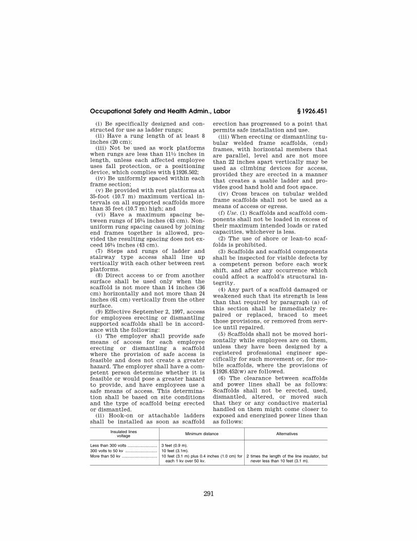
(6) The clearance between scaffolds and power lines shall be as follows: Scaffolds shall not be erected, used, dismantled, altered, or moved such that they or any conductive material handled on them might come closer to exposed and energized power lines than as follows:
Insulated lines voltage Minimum distance Alternatives
Less than 300 volts .......................... 3 feet (0.9 m).300 volts to 50 kv ............................ 10 feet (3.1m).More than 50 kv ............................... 10 feet (3.1 m) plus 0.4 inches (1.0 cm) for
each 1 kv over 50 kv.2 times the length of the line insulator, but
never less than 10 feet (3.1 m).
VerDate Mar<15>2010 15:51 Sep 16, 2011 Jkt 223116 PO 00000 Frm 00301 Fmt 8010 Sfmt 8010 Q:\29\29V8.TXT ofr150 PsN: PC150
292
29 CFR Ch. XVII (7–1–11 Edition) § 1926.451
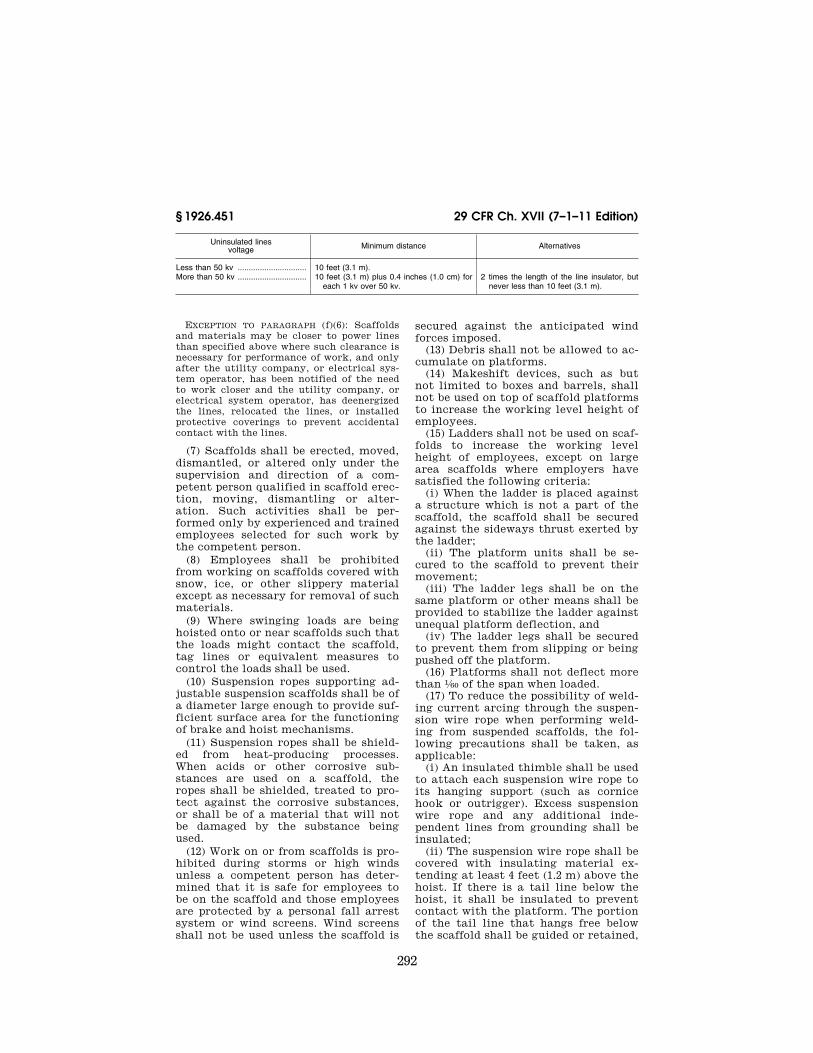
Uninsulated lines voltage Minimum distance Alternatives
Less than 50 kv ............................... 10 feet (3.1 m).More than 50 kv ............................... 10 feet (3.1 m) plus 0.4 inches (1.0 cm) for
each 1 kv over 50 kv.2 times the length of the line insulator, but
never less than 10 feet (3.1 m).
EXCEPTION TO PARAGRAPH (f)(6): Scaffolds and materials may be closer to power lines than specified above where such clearance is necessary for performance of work, and only after the utility company, or electrical sys-tem operator, has been notified of the need to work closer and the utility company, or electrical system operator, has deenergized the lines, relocated the lines, or installed protective coverings to prevent accidental contact with the lines.
(7) Scaffolds shall be erected, moved, dismantled, or altered only under the supervision and direction of a com-petent person qualified in scaffold erec-tion, moving, dismantling or alter-ation. Such activities shall be per-formed only by experienced and trained employees selected for such work by the competent person.
(8) Employees shall be prohibited from working on scaffolds covered with snow, ice, or other slippery material except as necessary for removal of such materials.
(9) Where swinging loads are being hoisted onto or near scaffolds such that the loads might contact the scaffold, tag lines or equivalent measures to control the loads shall be used.
(10) Suspension ropes supporting ad-justable suspension scaffolds shall be of a diameter large enough to provide suf-ficient surface area for the functioning of brake and hoist mechanisms.
(11) Suspension ropes shall be shield-ed from heat-producing processes. When acids or other corrosive sub-stances are used on a scaffold, the ropes shall be shielded, treated to pro-tect against the corrosive substances, or shall be of a material that will not be damaged by the substance being used.
(12) Work on or from scaffolds is pro-hibited during storms or high winds unless a competent person has deter-mined that it is safe for employees to be on the scaffold and those employees are protected by a personal fall arrest system or wind screens. Wind screens shall not be used unless the scaffold is
secured against the anticipated wind forces imposed.
(13) Debris shall not be allowed to ac-cumulate on platforms.
(14) Makeshift devices, such as but not limited to boxes and barrels, shall not be used on top of scaffold platforms to increase the working level height of employees.
(15) Ladders shall not be used on scaf-folds to increase the working level height of employees, except on large area scaffolds where employers have satisfied the following criteria:
(i) When the ladder is placed against a structure which is not a part of the scaffold, the scaffold shall be secured against the sideways thrust exerted by the ladder;
(ii) The platform units shall be se-cured to the scaffold to prevent their movement;
(iii) The ladder legs shall be on the same platform or other means shall be provided to stabilize the ladder against unequal platform deflection, and
(iv) The ladder legs shall be secured to prevent them from slipping or being pushed off the platform.
(16) Platforms shall not deflect more than 1⁄60 of the span when loaded.
(17) To reduce the possibility of weld-ing current arcing through the suspen-sion wire rope when performing weld-ing from suspended scaffolds, the fol-lowing precautions shall be taken, as applicable:
(i) An insulated thimble shall be used to attach each suspension wire rope to its hanging support (such as cornice hook or outrigger). Excess suspension wire rope and any additional inde-pendent lines from grounding shall be insulated;
(ii) The suspension wire rope shall be covered with insulating material ex-tending at least 4 feet (1.2 m) above the hoist. If there is a tail line below the hoist, it shall be insulated to prevent contact with the platform. The portion of the tail line that hangs free below the scaffold shall be guided or retained,
VerDate Mar<15>2010 15:51 Sep 16, 2011 Jkt 223116 PO 00000 Frm 00302 Fmt 8010 Sfmt 8010 Q:\29\29V8.TXT ofr150 PsN: PC150
293
Occupational Safety and Health Admin., Labor § 1926.451
or both, so that it does not become grounded;
(iii) Each hoist shall be covered with insulated protective covers;
(iv) In addition to a work lead at-tachment required by the welding proc-ess, a grounding conductor shall be connected from the scaffold to the structure. The size of this conductor shall be at least the size of the welding process work lead, and this conductor shall not be in series with the welding process or the work piece;
(v) If the scaffold grounding lead is disconnected at any time, the welding machine shall be shut off; and
(vi) An active welding rod or uninsulated welding lead shall not be allowed to contact the scaffold or its suspension system.
(g) Fall protection. (1) Each employee on a scaffold more than 10 feet (3.1 m) above a lower level shall be protected from falling to that lower level. Para-graphs (g)(1) (i) through (vii) of this section establish the types of fall pro-tection to be provided to the employees on each type of scaffold. Paragraph (g)(2) of this section addresses fall pro-tection for scaffold erectors and dis-mantlers.
NOTE TO PARAGRAPH (g)(1): The fall protec-tion requirements for employees installing suspension scaffold support systems on floors, roofs, and other elevated surfaces are set forth in subpart M of this part.
(i) Each employee on a boatswains’ chair, catenary scaffold, float scaffold, needle beam scaffold, or ladder jack scaffold shall be protected by a per-sonal fall arrest system;
(ii) Each employee on a single-point or two-point adjustable suspension scaffold shall be protected by both a personal fall arrest system and guard-rail system;
(iii) Each employee on a crawling board (chicken ladder) shall be pro-tected by a personal fall arrest system, a guardrail system (with minimum 200 pound toprail capacity), or by a three- fourth inch (1.9 cm) diameter grabline or equivalent handhold securely fas-tened beside each crawling board;
(iv) Each employee on a self-con-tained adjustable scaffold shall be pro-tected by a guardrail system (with minimum 200 pound toprail capacity) when the platform is supported by the
frame structure, and by both a per-sonal fall arrest system and a guardrail system (with minimum 200 pound top-rail capacity) when the platform is sup-ported by ropes;
(v) Each employee on a walkway lo-cated within a scaffold shall be pro-tected by a guardrail system (with minimum 200 pound toprail capacity) installed within 91⁄2 inches (24.1 cm) of and along at least one side of the walk-way.
(vi) Each employee performing overhand bricklaying operations from a supported scaffold shall be protected from falling from all open sides and ends of the scaffold (except at the side next to the wall being laid) by the use of a personal fall arrest system or guardrail system (with minimum 200 pound toprail capacity).
(vii) For all scaffolds not otherwise specified in paragraphs (g)(1)(i) through (g)(1)(vi) of this section, each employee shall be protected by the use of per-sonal fall arrest systems or guardrail systems meeting the requirements of paragraph (g)(4) of this section.
(2) Effective September 2, 1997, the employer shall have a competent per-son determine the feasibility and safe-ty of providing fall protection for em-ployees erecting or dismantling sup-ported scaffolds. Employers are re-quired to provide fall protection for employees erecting or dismantling sup-ported scaffolds where the installation and use of such protection is feasible and does not create a greater hazard.
(3) In addition to meeting the re-quirements of § 1926.502(d), personal fall arrest systems used on scaffolds shall be attached by lanyard to a vertical lifeline, horizontal lifeline, or scaffold structural member. Vertical lifelines shall not be used when overhead com-ponents, such as overhead protection or additional platform levels, are part of a single-point or two-point adjust-able suspension scaffold.
(i) When vertical lifelines are used, they shall be fastened to a fixed safe point of anchorage, shall be inde-pendent of the scaffold, and shall be protected from sharp edges and abra-sion. Safe points of anchorage include structural members of buildings, but do not include standpipes, vents, other
VerDate Mar<15>2010 15:51 Sep 16, 2011 Jkt 223116 PO 00000 Frm 00303 Fmt 8010 Sfmt 8010 Q:\29\29V8.TXT ofr150 PsN: PC150

294
29 CFR Ch. XVII (7–1–11 Edition) § 1926.451
piping systems, electrical conduit, out-rigger beams, or counterweights.
(ii) When horizontal lifelines are used, they shall be secured to two or more structural members of the scaf-fold, or they may be looped around both suspension and independent sus-pension lines (on scaffolds so equipped) above the hoist and brake attached to the end of the scaffold. Horizontal life-lines shall not be attached only to the suspension ropes.
(iii) When lanyards are connected to horizontal lifelines or structural mem-bers on a single-point or two-point ad-justable suspension scaffold, the scaf-fold shall be equipped with additional independent support lines and auto-matic locking devices capable of stop-ping the fall of the scaffold in the event one or both of the suspension ropes fail. The independent support lines shall be equal in number and strength to the suspension ropes.
(iv) Vertical lifelines, independent support lines, and suspension ropes shall not be attached to each other, nor shall they be attached to or use the same point of anchorage, nor shall they be attached to the same point on the scaffold or personal fall arrest system.
(4) Guardrail systems installed to meet the requirements of this section shall comply with the following provi-sions (guardrail systems built in ac-cordance with appendix A to this sub-part will be deemed to meet the re-quirements of paragraphs (g)(4) (vii), (viii), and (ix) of this section):
(i) Guardrail systems shall be in-stalled along all open sides and ends of platforms. Guardrail systems shall be installed before the scaffold is released for use by employees other than erec-tion/dismantling crews.
(ii) The top edge height of toprails or equivalent member on supported scaf-folds manufactured or placed in service after January 1, 2000 shall be installed between 38 inches (0.97 m) and 45 inches (1.2 m) above the platform surface. The top edge height on supported scaffolds manufactured and placed in service be-fore January 1, 2000, and on all sus-pended scaffolds where both a guardrail and a personal fall arrest system are required shall be between 36 inches (0.9 m) and 45 inches (1.2 m). When condi-tions warrant, the height of the top
edge may exceed the 45-inch height, provided the guardrail system meets all other criteria of paragraph (g)(4).
(iii) When midrails, screens, mesh, intermediate vertical members, solid panels, or equivalent structural mem-bers are used, they shall be installed between the top edge of the guardrail system and the scaffold platform.
(iv) When midrails are used, they shall be installed at a height approxi-mately midway between the top edge of the guardrail system and the platform surface.
(v) When screens and mesh are used, they shall extend from the top edge of the guardrail system to the scaffold platform, and along the entire opening between the supports.
(vi) When intermediate members (such as balusters or additional rails) are used, they shall not be more than 19 inches (48 cm) apart.
(vii) Each toprail or equivalent mem-ber of a guardrail system shall be capa-ble of withstanding, without failure, a force applied in any downward or hori-zontal direction at any point along its top edge of at least 100 pounds (445 n) for guardrail systems installed on sin-gle-point adjustable suspension scaf-folds or two-point adjustable suspen-sion scaffolds, and at least 200 pounds (890 n) for guardrail systems installed on all other scaffolds.
(viii) When the loads specified in paragraph (g)(4)(vii) of this section are applied in a downward direction, the top edge shall not drop below the height above the platform surface that is prescribed in paragraph (g)(4)(ii) of this section.
(ix) Midrails, screens, mesh, inter-mediate vertical members, solid pan-els, and equivalent structural members of a guardrail system shall be capable of withstanding, without failure, a force applied in any downward or hori-zontal direction at any point along the midrail or other member of at least 75 pounds (333 n) for guardrail systems with a minimum 100 pound toprail ca-pacity, and at least 150 pounds (666 n) for guardrail systems with a minimum 200 pound toprail capacity.
(x) Suspension scaffold hoists and non-walk-through stirrups may be used as end guardrails, if the space between
VerDate Mar<15>2010 15:51 Sep 16, 2011 Jkt 223116 PO 00000 Frm 00304 Fmt 8010 Sfmt 8010 Q:\29\29V8.TXT ofr150 PsN: PC150
295
Occupational Safety and Health Admin., Labor § 1926.451
the hoist or stirrup and the side guard-rail or structure does not allow passage of an employee to the end of the scaf-fold.
(xi) Guardrails shall be surfaced to prevent injury to an employee from punctures or lacerations, and to pre-vent snagging of clothing.
(xii) The ends of all rails shall not overhang the terminal posts except when such overhang does not con-stitute a projection hazard to employ-ees.
(xiii) Steel or plastic banding shall not be used as a toprail or midrail.
(xiv) Manila or plastic (or other syn-thetic) rope being used for toprails or midrails shall be inspected by a com-petent person as frequently as nec-essary to ensure that it continues to meet the strength requirements of paragraph (g) of this section.
(xv) Crossbracing is acceptable in place of a midrail when the crossing point of two braces is between 20 inches (0.5 m) and 30 inches (0.8 m) above the work platform or as a toprail when the crossing point of two braces is between 38 inches (0.97 m) and 48 inches (1.3 m) above the work platform. The end points at each upright shall be no more than 48 inches (1.3 m) apart.
(h) Falling object protection. (1) In ad-dition to wearing hardhats each em-ployee on a scaffold shall be provided with additional protection from falling hand tools, debris, and other small ob-jects through the installation of toeboards, screens, or guardrail sys-tems, or through the erection of debris nets, catch platforms, or canopy struc-tures that contain or deflect the falling objects. When the falling objects are too large, heavy or massive to be con-tained or deflected by any of the above- listed measures, the employer shall place such potential falling objects away from the edge of the surface from which they could fall and shall secure those materials as necessary to prevent their falling.
(2) Where there is a danger of tools, materials, or equipment falling from a scaffold and striking employees below, the following provisions apply:
(i) The area below the scaffold to which objects can fall shall be barri-caded, and employees shall not be per-mitted to enter the hazard area; or
(ii) A toeboard shall be erected along the edge of platforms more than 10 feet (3.1 m) above lower levels for a distance sufficient to protect employees below, except on float (ship) scaffolds where an edging of 3⁄4 × 11⁄2 inch (2 × 4 cm) wood or equivalent may be used in lieu of toeboards;
(iii) Where tools, materials, or equip-ment are piled to a height higher than the top edge of the toeboard, paneling or screening extending from the toeboard or platform to the top of the guardrail shall be erected for a dis-tance sufficient to protect employees below; or
(iv) A guardrail system shall be in-stalled with openings small enough to prevent passage of potential falling ob-jects; or
(v) A canopy structure, debris net, or catch platform strong enough to with-stand the impact forces of the poten-tial falling objects shall be erected over the employees below.
(3) Canopies, when used for falling ob-ject protection, shall comply with the following criteria:
(i) Canopies shall be installed be-tween the falling object hazard and the employees.
(ii) When canopies are used on sus-pension scaffolds for falling object pro-tection, the scaffold shall be equipped with additional independent support lines equal in number to the number of points supported, and equivalent in strength to the strength of the suspen-sion ropes.
(iii) Independent support lines and suspension ropes shall not be attached to the same points of anchorage.
(4) Where used, toeboards shall be: (i) Capable of withstanding, without
failure, a force of at least 50 pounds (222 n) applied in any downward or hor-izontal direction at any point along the toeboard (toeboards built in accord-ance with appendix A to this subpart will be deemed to meet this require-ment); and
(ii) At least three and one-half inches (9 cm) high from the top edge of the toeboard to the level of the walking/ working surface. Toeboards shall be se-curely fastened in place at the outer-most edge of the platform and have not more than 1⁄4 inch (0.7 cm) clearance above the walking/working surface.
VerDate Mar<15>2010 15:51 Sep 16, 2011 Jkt 223116 PO 00000 Frm 00305 Fmt 8010 Sfmt 8010 Q:\29\29V8.TXT ofr150 PsN: PC150
296
29 CFR Ch. XVII (7–1–11 Edition) § 1926.452
Toeboards shall be solid or with open-ings not over one inch (2.5 cm) in the greatest dimension.
[61 FR 46107, Aug. 30, 1996, as corrected and amended at 61 FR 59831, 59832, Nov. 25, 1996]
EFFECTIVE DATE NOTE: At 61 FR 59832, Nov. 25, 1996, § 1926.451(b)(2)(i) was amended and certain requirements stayed until Nov. 25, 1997, or until further rulemaking has been completed, whichever is later.
§ 1926.452 Additional requirements ap-plicable to specific types of scaf-folds.
In addition to the applicable require-ments of § 1926.451, the following re-quirements apply to the specific types of scaffolds indicated. Scaffolds not specifically addressed by § 1926.452, such as but not limited to systems scaffolds, must meet the requirements of § 1926.451.
(a) Pole scaffolds. (1) When platforms are being moved to the next level, the existing platform shall be left undis-turbed until the new bearers have been set in place and braced, prior to receiv-ing the new platforms.
(2) Crossbracing shall be installed be-tween the inner and outer sets of poles on double pole scaffolds.
(3) Diagonal bracing in both direc-tions shall be installed across the en-tire inside face of double-pole scaffolds used to support loads equivalent to a uniformly distributed load of 50 pounds (222 kg) or more per square foot (929 square cm).
(4) Diagonal bracing in both direc-tions shall be installed across the en-tire outside face of all double- and sin-gle-pole scaffolds.
(5) Runners and bearers shall be in-stalled on edge.
(6) Bearers shall extend a minimum of 3 inches (7.6 cm) over the outside edges of runners.
(7) Runners shall extend over a min-imum of two poles, and shall be sup-ported by bearing blocks securely at-tached to the poles.
(8) Braces, bearers, and runners shall not be spliced between poles.
(9) Where wooden poles are spliced, the ends shall be squared and the upper section shall rest squarely on the lower section. Wood splice plates shall be provided on at least two adjacent sides, and shall extend at least 2 feet (0.6 m)
on either side of the splice, overlap the abutted ends equally, and have at least the same cross-sectional areas as the pole. Splice plates of other materials of equivalent strength may be used.
(10) Pole scaffolds over 60 feet in height shall be designed by a registered professional engineer, and shall be con-structed and loaded in accordance with that design. Non-mandatory appendix A to this subpart contains examples of criteria that will enable an employer to comply with design and loading re-quirements for pole scaffolds under 60 feet in height.
(b) Tube and coupler scaffolds. (1) When platforms are being moved to the next level, the existing platform shall be left undisturbed until the new bear-ers have been set in place and braced prior to receiving the new platforms.
(2) Transverse bracing forming an ‘‘X’’ across the width of the scaffold shall be installed at the scaffold ends and at least at every third set of posts horizontally (measured from only one end) and every fourth runner vertically. Bracing shall extend diago-nally from the inner or outer posts or runners upward to the next outer or inner posts or runners. Building ties shall be installed at the bearer levels between the transverse bracing and shall conform to the requirements of § 1926.451(c)(1).
(3) On straight run scaffolds, longitu-dinal bracing across the inner and outer rows of posts shall be installed diagonally in both directions, and shall extend from the base of the end posts upward to the top of the scaffold at ap-proximately a 45 degree angle. On scaf-folds whose length is greater than their height, such bracing shall be repeated beginning at least at every fifth post. On scaffolds whose length is less than their height, such bracing shall be in-stalled from the base of the end posts upward to the opposite end posts, and then in alternating directions until reaching the top of the scaffold. Brac-ing shall be installed as close as pos-sible to the intersection of the bearer and post or runner and post.
(4) Where conditions preclude the at-tachment of bracing to posts, bracing shall be attached to the runners as close to the post as possible.
VerDate Mar<15>2010 15:51 Sep 16, 2011 Jkt 223116 PO 00000 Frm 00306 Fmt 8010 Sfmt 8010 Q:\29\29V8.TXT ofr150 PsN: PC150

297
Occupational Safety and Health Admin., Labor § 1926.452
(5) Bearers shall be installed trans-versely between posts, and when cou-pled to the posts, shall have the in-board coupler bear directly on the run-ner coupler. When the bearers are cou-pled to the runners, the couplers shall be as close to the posts as possible.
(6) Bearers shall extend beyond the posts and runners, and shall provide full contact with the coupler.
(7) Runners shall be installed along the length of the scaffold, located on both the inside and outside posts at level heights (when tube and coupler guardrails and midrails are used on outside posts, they may be used in lieu of outside runners).
(8) Runners shall be interlocked on straight runs to form continuous lengths, and shall be coupled to each post. The bottom runners and bearers shall be located as close to the base as possible.
(9) Couplers shall be of a structural metal, such as drop-forged steel, malle-able iron, or structural grade alu-minum. The use of gray cast iron is prohibited.
(10) Tube and coupler scaffolds over 125 feet in height shall be designed by a registered professional engineer, and shall be constructed and loaded in ac-cordance with such design. Non-manda-tory appendix A to this subpart con-tains examples of criteria that will en-able an employer to comply with de-sign and loading requirements for tube and coupler scaffolds under 125 feet in height.
(c) Fabricated frame scaffolds (tubular welded frame scaffolds). (1) When mov-ing platforms to the next level, the ex-isting platform shall be left undis-turbed until the new end frames have been set in place and braced prior to re-ceiving the new platforms.
(2) Frames and panels shall be braced by cross, horizontal, or diagonal braces, or combination thereof, which secure vertical members together lat-erally. The cross braces shall be of such length as will automatically square and align vertical members so that the erected scaffold is always plumb, level, and square. All brace connections shall be secured.
(3) Frames and panels shall be joined together vertically by coupling or stacking pins or equivalent means.
(4) Where uplift can occur which would displace scaffold end frames or panels, the frames or panels shall be locked together vertically by pins or equivalent means.
(5) Brackets used to support canti-levered loads shall:
(i) Be seated with side-brackets par-allel to the frames and end-brackets at 90 degrees to the frames;
(ii) Not be bent or twisted from these positions; and
(iii) Be used only to support per-sonnel, unless the scaffold has been de-signed for other loads by a qualified en-gineer and built to withstand the tip-ping forces caused by those other loads being placed on the bracket-supported section of the scaffold.
(6) Scaffolds over 125 feet (38.0 m) in height above their base plates shall be designed by a registered professional engineer, and shall be constructed and loaded in accordance with such design.
(d) Plasterers’, decorators’, and large area scaffolds. Scaffolds shall be con-structed in accordance with paragraphs (a), (b), or (c) of this section, as appro-priate.
(e) Bricklayers’ square scaffolds (squares). (1) Scaffolds made of wood shall be reinforced with gussets on both sides of each corner.
(2) Diagonal braces shall be installed on all sides of each square.
(3) Diagonal braces shall be installed between squares on the rear and front sides of the scaffold, and shall extend from the bottom of each square to the top of the next square.
(4) Scaffolds shall not exceed three tiers in height, and shall be so con-structed and arranged that one square rests directly above the other. The upper tiers shall stand on a continuous row of planks laid across the next lower tier, and shall be nailed down or otherwise secured to prevent displace-ment.
(f) Horse scaffolds. (1) Scaffolds shall not be constructed or arranged more than two tiers or 10 feet (3.0 m) in height, whichever is less.
(2) When horses are arranged in tiers, each horse shall be placed directly over the horse in the tier below.
(3) When horses are arranged in tiers, the legs of each horse shall be nailed
VerDate Mar<15>2010 15:51 Sep 16, 2011 Jkt 223116 PO 00000 Frm 00307 Fmt 8010 Sfmt 8010 Q:\29\29V8.TXT ofr150 PsN: PC150
298
29 CFR Ch. XVII (7–1–11 Edition) § 1926.452
down or otherwise secured to prevent displacement.
(4) When horses are arranged in tiers, each tier shall be crossbraced.
(g) Form scaffolds and carpenters’ bracket scaffolds. (1) Each bracket, ex-cept those for wooden bracket-form scaffolds, shall be attached to the sup-porting formwork or structure by means of one or more of the following: nails; a metal stud attachment device; welding; hooking over a secured struc-tural supporting member, with the form wales either bolted to the form or secured by snap ties or tie bolts ex-tending through the form and securely anchored; or, for carpenters’ bracket scaffolds only, by a bolt extending through to the opposite side of the structure’s wall.
(2) Wooden bracket-form scaffolds shall be an integral part of the form panel.
(3) Folding type metal brackets, when extended for use, shall be either bolted or secured with a locking-type pin.
(h) Roof bracket scaffolds. (1) Scaffold brackets shall be constructed to fit the pitch of the roof and shall provide a level support for the platform.
(2) Brackets (including those pro-vided with pointed metal projections) shall be anchored in place by nails un-less it is impractical to use nails. When nails are not used, brackets shall be se-cured in place with first-grade manila rope of at least three-fourth inch (1.9 cm) diameter, or equivalent.
(i) Outrigger scaffolds. (1) The inboard end of outrigger beams, measured from the fulcrum point to the extreme point of anchorage, shall be not less than one and one-half times the outboard end in length.
(2) Outrigger beams fabricated in the shape of an I-beam or channel shall be placed so that the web section is vertical.
(3) The fulcrum point of outrigger beams shall rest on secure bearings at least 6 inches (15.2 cm) in each hori-zontal dimension.
(4) Outrigger beams shall be secured in place against movement, and shall be securely braced at the fulcrum point against tipping.
(5) The inboard ends of outrigger beams shall be securely anchored ei-
ther by means of braced struts bearing against sills in contact with the over-head beams or ceiling, or by means of tension members secured to the floor joists underfoot, or by both.
(6) The entire supporting structure shall be securely braced to prevent any horizontal movement.
(7) To prevent their displacement, platform units shall be nailed, bolted, or otherwise secured to outriggers.
(8) Scaffolds and scaffold components shall be designed by a registered pro-fessional engineer and shall be con-structed and loaded in accordance with such design.
(j) Pump jack scaffolds. (1) Pump jack brackets, braces, and accessories shall be fabricated from metal plates and an-gles. Each pump jack bracket shall have two positive gripping mechanisms to prevent any failure or slippage.
(2) Poles shall be secured to the structure by rigid triangular bracing or equivalent at the bottom, top, and other points as necessary. When the pump jack has to pass bracing already installed, an additional brace shall be installed approximately 4 feet (1.2 m) above the brace to be passed, and shall be left in place until the pump jack has been moved and the original brace re-installed.
(3) When guardrails are used for fall protection, a workbench may be used as the toprail only if it meets all the requirements in paragraphs (g)(4) (ii), (vii), (viii), and (xiii) of § 1926.451.
(4) Work benches shall not be used as scaffold platforms.
(5) When poles are made of wood, the pole lumber shall be straight-grained, free of shakes, large loose or dead knots, and other defects which might impair strength.
(6) When wood poles are constructed of two continuous lengths, they shall be joined together with the seam par-allel to the bracket.
(7) When two by fours are spliced to make a pole, mending plates shall be installed at all splices to develop the full strength of the member.
(k) Ladder jack scaffolds. (1) Platforms shall not exceed a height of 20 feet (6.1 m).
VerDate Mar<15>2010 15:51 Sep 16, 2011 Jkt 223116 PO 00000 Frm 00308 Fmt 8010 Sfmt 8010 Q:\29\29V8.TXT ofr150 PsN: PC150
299
Occupational Safety and Health Admin., Labor § 1926.452
(2) All ladders used to support ladder jack scaffolds shall meet the require-ments of subpart X of this part—Stair-ways and Ladders, except that job- made ladders shall not be used to sup-port ladder jack scaffolds.
(3) The ladder jack shall be so de-signed and constructed that it will bear on the side rails and ladder rungs or on the ladder rungs alone. If bearing on rungs only, the bearing area shall in-clude a length of at least 10 inches (25.4 cm) on each rung.
(4) Ladders used to support ladder jacks shall be placed, fastened, or equipped with devices to prevent slip-ping.
(5) Scaffold platforms shall not be bridged one to another.
(l) Window jack scaffolds. (1) Scaffolds shall be securely attached to the win-dow opening.
(2) Scaffolds shall be used only for the purpose of working at the window opening through which the jack is placed.
(3) Window jacks shall not be used to support planks placed between one win-dow jack and another, or for other ele-ments of scaffolding.
(m) Crawling boards (chicken ladders). (1) Crawling boards shall extend from the roof peak to the eaves when used in connection with roof construction, re-pair, or maintenance.
(2) Crawling boards shall be secured to the roof by ridge hooks or by means that meet equivalent criteria (e.g., strength and durability).
(n) Step, platform, and trestle ladder scaffolds. (1) Scaffold platforms shall not be placed any higher than the sec-ond highest rung or step of the ladder supporting the platform.
(2) All ladders used in conjunction with step, platform and trestle ladder scaffolds shall meet the pertinent re-quirements of subpart X of this part— Stairways and Ladders, except that job-made ladders shall not be used to support such scaffolds.
(3) Ladders used to support step, plat-form, and trestle ladder scaffolds shall be placed, fastened, or equipped with devices to prevent slipping.
(4) Scaffolds shall not be bridged one to another.
(o) Single-point adjustable suspension scaffolds. (1) When two single-point ad-
justable suspension scaffolds are com-bined to form a two-point adjustable suspension scaffold, the resulting two- point scaffold shall comply with the re-quirements for two-point adjustable suspension scaffolds in paragraph (p) of this section.
(2) The supporting rope between the scaffold and the suspension device shall be kept vertical unless all of the fol-lowing conditions are met:
(i) The rigging has been designed by a qualified person, and
(ii) The scaffold is accessible to res-cuers, and
(iii) The supporting rope is protected to ensure that it will not chafe at any point where a change in direction oc-curs, and
(iv) The scaffold is positioned so that swinging cannot bring the scaffold into contact with another surface.
(3) Boatswains’ chair tackle shall consist of correct size ball bearings or bushed blocks containing safety hooks and properly ‘‘eye-spliced’’ minimum five-eighth (5⁄8) inch (1.6 cm) diameter first-grade manila rope, or other rope which will satisfy the criteria (e.g., strength and durability) of manila rope.
(4) Boatswains’ chair seat slings shall be reeved through four corner holes in the seat; shall cross each other on the underside of the seat; and shall be rigged so as to prevent slippage which could cause an out-of-level condition.
(5) Boatswains’ chair seat slings shall be a minimum of five-eight (5⁄8) inch (1.6 cm) diameter fiber, synthetic, or other rope which will satisfy the cri-teria (e.g., strength, slip resistance, du-rability, etc.) of first grade manila rope.
(6) When a heat-producing process such as gas or arc welding is being con-ducted, boatswains’ chair seat slings shall be a minimum of three-eight (3⁄8) inch (1.0 cm) wire rope.
(7) Non-cross-laminated wood boat-swains’ chairs shall be reinforced on their underside by cleats securely fas-tened to prevent the board from split-ting.
(p) Two-point adjustable suspension scaffolds (swing stages). The following requirements do not apply to two-point adjustable suspension scaffolds used as masons’ or stonesetters’ scaffolds.
VerDate Mar<15>2010 15:51 Sep 16, 2011 Jkt 223116 PO 00000 Frm 00309 Fmt 8010 Sfmt 8010 Q:\29\29V8.TXT ofr150 PsN: PC150
300
29 CFR Ch. XVII (7–1–11 Edition) § 1926.452
Such scaffolds are covered by para-graph (q) of this section.
(1) Platforms shall not be more than 36 inches (0.9 m) wide unless designed by a qualified person to prevent unsta-ble conditions.
(2) The platform shall be securely fas-tened to hangers (stirrups) by U-bolts or by other means which satisfy the re-quirements of § 1926.451(a).
(3) The blocks for fiber or synthetic ropes shall consist of at least one dou-ble and one single block. The sheaves of all blocks shall fit the size of the rope used.
(4) Platforms shall be of the ladder- type, plank-type, beam-type, or light- metal type. Light metal-type plat-forms having a rated capacity of 750 pounds or less and platforms 40 feet (12.2 m) or less in length shall be tested and listed by a nationally recognized testing laboratory.
(5) Two-point scaffolds shall not be bridged or otherwise connected one to another during raising and lowering operations unless the bridge connec-tions are articulated (attached), and the hoists properly sized.
(6) Passage may be made from one platform to another only when the platforms are at the same height, are abutting, and walk-through stirrups specifically designed for this purpose are used.
(q) Multi-point adjustable suspension scaffolds, stonesetters’ multi-point adjust-able suspension scaffolds, and masons’ multi-point adjustable suspension scaf-folds. (1) When two or more scaffolds are used they shall not be bridged one to another unless they are designed to be bridged, the bridge connections are articulated, and the hoists are properly sized.
(2) If bridges are not used, passage may be made from one platform to an-other only when the platforms are at the same height and are abutting.
(3) Scaffolds shall be suspended from metal outriggers, brackets, wire rope slings, hooks, or means that meet equivalent criteria (e.g., strength, du-rability).
(r) Catenary scaffolds. (1) No more than one platform shall be placed be-tween consecutive vertical pickups, and no more than two platforms shall be used on a catenary scaffold.
(2) Platforms supported by wire ropes shall have hook-shaped stops on each end of the platforms to prevent them from slipping off the wire ropes. These hooks shall be so placed that they will prevent the platform from falling if one of the horizontal wire ropes breaks.
(3) Wire ropes shall not be tightened to the extent that the application of a scaffold load will overstress them.
(4) Wire ropes shall be continuous and without splices between anchors.
(s) Float (ship) scaffolds. (1) The plat-form shall be supported by a minimum of two bearers, each of which shall project a minimum of 6 inches (15.2 cm) beyond the platform on both sides. Each bearer shall be securely fastened to the platform.
(2) Rope connections shall be such that the platform cannot shift or slip.
(3) When only two ropes are used with each float:
(i) They shall be arranged so as to provide four ends which are securely fastened to overhead supports.
(ii) Each supporting rope shall be hitched around one end of the bearer and pass under the platform to the other end of the bearer where it is hitched again, leaving sufficient rope at each end for the supporting ties.
(t) Interior hung scaffolds. (1) Scaf-folds shall be suspended only from the roof structure or other structural member such as ceiling beams.
(2) Overhead supporting members (roof structure, ceiling beams, or other structural members) shall be inspected and checked for strength before the scaffold is erected.
(3) Suspension ropes and cables shall be connected to the overhead sup-porting members by shackles, clips, thimbles, or other means that meet equivalent criteria (e.g., strength, du-rability).
(u) Needle beam scaffolds. (1) Scaffold support beams shall be installed on edge.
(2) Ropes or hangers shall be used for supports, except that one end of a nee-dle beam scaffold may be supported by a permanent structural member.
(3) The ropes shall be securely at-tached to the needle beams.
(4) The support connection shall be arranged so as to prevent the needle
VerDate Mar<15>2010 15:51 Sep 16, 2011 Jkt 223116 PO 00000 Frm 00310 Fmt 8010 Sfmt 8010 Q:\29\29V8.TXT ofr150 PsN: PC150
301
Occupational Safety and Health Admin., Labor § 1926.452
beam from rolling or becoming dis-placed.
(5) Platform units shall be securely attached to the needle beams by bolts or equivalent means. Cleats and over-hang are not considered to be adequate means of attachment.
(v) Multi-level suspended scaffolds. (1) Scaffolds shall be equipped with addi-tional independent support lines, equal in number to the number of points sup-ported, and of equivalent strength to the suspension ropes, and rigged to support the scaffold in the event the suspension rope(s) fail.
(2) Independent support lines and sus-pension ropes shall not be attached to the same points of anchorage.
(3) Supports for platforms shall be at-tached directly to the support stirrup and not to any other platform.
(w) Mobile scaffolds. (1) Scaffolds shall be braced by cross, horizontal, or di-agonal braces, or combination thereof, to prevent racking or collapse of the scaffold and to secure vertical mem-bers together laterally so as to auto-matically square and align the vertical members. Scaffolds shall be plumb, level, and squared. All brace connec-tions shall be secured.
(i) Scaffolds constructed of tube and coupler components shall also comply with the requirements of paragraph (b) of this section;
(ii) Scaffolds constructed of fab-ricated frame components shall also comply with the requirements of para-graph (c) of this section.
(2) Scaffold casters and wheels shall be locked with positive wheel and/or wheel and swivel locks, or equivalent means, to prevent movement of the scaffold while the scaffold is used in a stationary manner.
(3) Manual force used to move the scaffold shall be applied as close to the base as practicable, but not more than 5 feet (1.5 m) above the supporting sur-face.
(4) Power systems used to propel mo-bile scaffolds shall be designed for such use. Forklifts, trucks, similar motor vehicles or add-on motors shall not be used to propel scaffolds unless the scaf-fold is designed for such propulsion sys-tems.
(5) Scaffolds shall be stabilized to prevent tipping during movement.
(6) Employees shall not be allowed to ride on scaffolds unless the following conditions exist:
(i) The surface on which the scaffold is being moved is within 3 degrees of level, and free of pits, holes, and ob-structions;
(ii) The height to base width ratio of the scaffold during movement is two to one or less, unless the scaffold is de-signed and constructed to meet or ex-ceed nationally recognized stability test requirements such as those listed in paragraph (x) of appendix A to this subpart (ANSI/SIA A92.5 and A92.6);
(iii) Outrigger frames, when used, are installed on both sides of the scaffold;
(iv) When power systems are used, the propelling force is applied directly to the wheels, and does not produce a speed in excess of 1 foot per second (.3 mps); and
(v) No employee is on any part of the scaffold which extends outward beyond the wheels, casters, or other supports.
(7) Platforms shall not extend out-ward beyond the base supports of the scaffold unless outrigger frames or equivalent devices are used to ensure stability.
(8) Where leveling of the scaffold is necessary, screw jacks or equivalent means shall be used.
(9) Caster stems and wheel stems shall be pinned or otherwise secured in scaffold legs or adjustment screws.
(10) Before a scaffold is moved, each employee on the scaffold shall be made aware of the move.
(x) Repair bracket scaffolds. (1) Brack-ets shall be secured in place by at least one wire rope at least 1⁄2 inch (1.27 cm) in diameter.
(2) Each bracket shall be attached to the securing wire rope (or ropes) by a positive locking device capable of pre-venting the unintentional detachment of the bracket from the rope, or by equivalent means.
(3) Each bracket, at the contact point between the supporting structure and the bottom of the bracket, shall be pro-vided with a shoe (heel block or foot) capable of preventing the lateral move-ment of the bracket.
(4) Platforms shall be secured to the brackets in a manner that will prevent the separation of the platforms from the brackets and the movement of the
VerDate Mar<15>2010 15:51 Sep 16, 2011 Jkt 223116 PO 00000 Frm 00311 Fmt 8010 Sfmt 8010 Q:\29\29V8.TXT ofr150 PsN: PC150
302
29 CFR Ch. XVII (7–1–11 Edition) § 1926.453
platforms or the brackets on a com-pleted scaffold.
(5) When a wire rope is placed around the structure in order to provide a safe anchorage for personal fall arrest sys-tems used by employees erecting or dismantling scaffolds, the wire rope shall meet the requirements of subpart M of this part, but shall be at least 5⁄16 inch (0.8 cm) in diameter.
(6) Each wire rope used for securing brackets in place or as an anchorage for personal fall arrest systems shall be protected from damage due to contact with edges, corners, protrusions, or other discontinuities of the supporting structure or scaffold components.
(7) Tensioning of each wire rope used for securing brackets in place or as an anchorage for personal fall arrest sys-tems shall be by means of a turnbuckle at least 1 inch (2.54 cm) in diameter, or by equivalent means.
(8) Each turnbuckle shall be con-nected to the other end of its rope by use of an eyesplice thimble of a size ap-propriate to the turnbuckle to which it is attached.
(9) U-bolt wire rope clips shall not be used on any wire rope used to secure brackets or to serve as an anchor for personal fall arrest systems.
(10) The employer shall ensure that materials shall not be dropped to the outside of the supporting structure.
(11) Scaffold erection shall progress in only one direction around any struc-ture.
(y) Stilts. Stilts, when used, shall be used in accordance with the following requirements:
(1) An employee may wear stilts on a scaffold only if it is a large area scaf-fold.
(2) When an employee is using stilts on a large area scaffold where a guard-rail system is used to provide fall pro-tection, the guardrail system shall be increased in height by an amount equal to the height of the stilts being used by the employee.
(3) Surfaces on which stilts are used shall be flat and free of pits, holes and obstructions, such as debris, as well as other tripping and falling hazards.
(4) Stilts shall be properly main-tained. Any alteration of the original equipment shall be approved by the manufacturer.
§ 1926.453 Aerial lifts. (a) General requirements. (1) Unless
otherwise provided in this section, aer-ial lifts acquired for use on or after January 22, 1973 shall be designed and constructed in conformance with the applicable requirements of the Amer-ican National Standards for ‘‘Vehicle Mounted Elevating and Rotating Work Platforms,’’ ANSI A92.2–1969, including appendix. Aerial lifts acquired before January 22, 1973 which do not meet the requirements of ANSI A92.2–1969, may not be used after January 1, 1976, un-less they shall have been modified so as to conform with the applicable design and construction requirements of ANSI A92.2–1969. Aerial lifts include the fol-lowing types of vehicle-mounted aerial devices used to elevate personnel to job-sites above ground:
(i) Extensible boom platforms; (ii) Aerial ladders; (iii) Articulating boom platforms; (iv) Vertical towers; and (v) A combination of any such de-
vices. Aerial equipment may be made of metal, wood, fiberglass reinforced plastic (FRP), or other material; may be powered or manually operated; and are deemed to be aerial lifts whether or not they are capable of rotating about a substantially vertical axis.
(2) Aerial lifts may be ‘‘field modi-fied’’ for uses other than those in-tended by the manufacturer provided the modification has been certified in writing by the manufacturer or by any other equivalent entity, such as a na-tionally recognized testing laboratory, to be in conformity with all applicable provisions of ANSI A92.2–1969 and this section and to be at least as safe as the equipment was before modification.
(b) Specific requirements—(1) Ladder trucks and tower trucks. Aerial ladders shall be secured in the lower traveling position by the locking device on top of the truck cab, and the manually oper-ated device at the base of the ladder be-fore the truck is moved for highway travel.
(2) Extensible and articulating boom platforms. (i) Lift controls shall be test-ed each day prior to use to determine that such controls are in safe working condition.
(ii) Only authorized persons shall op-erate an aerial lift.
VerDate Mar<15>2010 15:51 Sep 16, 2011 Jkt 223116 PO 00000 Frm 00312 Fmt 8010 Sfmt 8010 Q:\29\29V8.TXT ofr150 PsN: PC150

303
Occupational Safety and Health Admin., Labor § 1926.453
(iii) Belting off to an adjacent pole, structure, or equipment while working from an aerial lift shall not be per-mitted.
(iv) Employees shall always stand firmly on the floor of the basket, and shall not sit or climb on the edge of the basket or use planks, ladders, or other devices for a work position.
(v) A body belt shall be worn and a lanyard attached to the boom or bas-ket when working from an aerial lift.
NOTE TO PARAGRAPH (b)(2)(v): As of Janu-ary 1, 1998, subpart M of this part (§ 1926.502(d)) provides that body belts are not acceptable as part of a personal fall arrest system. The use of a body belt in a tethering system or in a restraint system is acceptable and is regulated under § 1926.502(e).
(vi) Boom and basket load limits specified by the manufacturer shall not be exceeded.
(vii) The brakes shall be set and when outriggers are used, they shall be posi-tioned on pads or a solid surface. Wheel chocks shall be installed before using an aerial lift on an incline, provided they can be safely installed.
(viii) An aerial lift truck shall not be moved when the boom is elevated in a working position with men in the bas-ket, except for equipment which is spe-cifically designed for this type of oper-ation in accordance with the provisions of paragraphs (a) (1) and (2) of this sec-tion.
(ix) Articulating boom and extensible boom platforms, primarily designed as personnel carriers, shall have both platform (upper) and lower controls. Upper controls shall be in or beside the platform within easy reach of the oper-ator. Lower controls shall provide for overriding the upper controls. Controls shall be plainly marked as to their function. Lower level controls shall not be operated unless permission has been obtained from the employee in the lift, except in case of emergency.
(x) Climbers shall not be worn while performing work from an aerial lift.
(xi) The insulated portion of an aerial lift shall not be altered in any manner that might reduce its insulating value.
(xii) Before moving an aerial lift for travel, the boom(s) shall be inspected to see that it is properly cradled and outriggers are in stowed position ex-
cept as provided in paragraph (b)(2)(viii) of this section.
(3) Electrical tests. All electrical tests shall conform to the requirements of ANSI A92.2–1969 section 5. However equivalent d.c.; voltage tests may be used in lieu of the a.c. voltage specified in A92.2–1969; d.c. voltage tests which are approved by the equipment manu-facturer or equivalent entity shall be considered an equivalent test for the purpose of this paragraph (b)(3).
(4) Bursting safety factor. The provi-sions of the American National Stand-ards Institute standard ANSI A92.2– 1969, section 4.9 Bursting Safety Factor shall apply to all critical hydraulic and pneumatic components. Critical com-ponents are those in which a failure would result in a free fall or free rota-tion of the boom. All noncritical com-ponents shall have a bursting safety factor of at least 2 to 1.
(5) Welding standards. All welding shall conform to the following stand-ards as applicable:
(i) Standard Qualification Procedure, AWS B3.0–41.
(ii) Recommended Practices for Automotive Welding Design, AWS D8.4–61.
(iii) Standard Qualification of Weld-ing Procedures and Welders for Piping and Tubing, AWS D10.9–69.
(iv) Specifications for Welding High-way and Railway Bridges, AWS D2.0–69.
NOTE TO § 1926.453: Non-mandatory appen-dix C to this subpart lists examples of na-tional consensus standards that are consid-ered to provide employee protection equiva-lent to that provided through the application of ANSI A92.2–1969, where appropriate. This incorporation by reference was approved by the Director of the Federal Register in ac-cordance with 5 U.S.C. 552(a) and 1 CFR part 51. Copies may be obtained from the Amer-ican National Standards Institute. Copies may be inspected at the Docket Office, Occu-pational Safety and Health Administration, U.S. Department of Labor, 200 Constitution Avenue, NW., room N2634, Washington, DC or at the National Archives and Records Ad-ministration (NARA). For information on the availability of this material at NARA, call 202–741–6030, or go to: http:// www.archives.gov/federallregister/ codeloflfederallregulations/ ibrllocations.html.
[61 FR 46116, Aug. 30, 1996; 61 FR 59832, Nov. 25, 1996, as amended at 69 FR 18803, Apr. 9, 2004]
VerDate Mar<15>2010 15:51 Sep 16, 2011 Jkt 223116 PO 00000 Frm 00313 Fmt 8010 Sfmt 8010 Q:\29\29V8.TXT ofr150 PsN: PC150

304
29 CFR Ch. XVII (7–1–11 Edition) § 1926.454
§ 1926.454 Training requirements. This section supplements and clari-
fies the requirements of § 1926.21(b)(2) as these relate to the hazards of work on scaffolds.
(a) The employer shall have each em-ployee who performs work while on a scaffold trained by a person qualified in the subject matter to recognize the hazards associated with the type of scaffold being used and to understand the procedures to control or minimize those hazards. The training shall in-clude the following areas, as applica-ble:
(1) The nature of any electrical haz-ards, fall hazards and falling object hazards in the work area;
(2) The correct procedures for dealing with electrical hazards and for erect-ing, maintaining, and disassembling the fall protection systems and falling object protection systems being used;
(3) The proper use of the scaffold, and the proper handling of materials on the scaffold;
(4) The maximum intended load and the load-carrying capacities of the scaffolds used; and
(5) Any other pertinent requirements of this subpart.
(b) The employer shall have each em-ployee who is involved in erecting, dis-assembling, moving, operating, repair-ing, maintaining, or inspecting a scaf-fold trained by a competent person to recognize any hazards associated with the work in question. The training shall include the following topics, as applicable:
(1) The nature of scaffold hazards; (2) The correct procedures for erect-
ing, disassembling, moving, operating, repairing, inspecting, and maintaining the type of scaffold in question;
(3) The design criteria, maximum in-tended load-carrying capacity and in-tended use of the scaffold;
(4) Any other pertinent requirements of this subpart.
(c) When the employer has reason to believe that an employee lacks the skill or understanding needed for safe work involving the erection, use or dis-mantling of scaffolds, the employer shall retrain each such employee so that the requisite proficiency is re-gained. Retraining is required in at least the following situations:
(1) Where changes at the worksite present a hazard about which an em-ployee has not been previously trained; or
(2) Where changes in the types of scaffolds, fall protection, falling object protection, or other equipment present a hazard about which an employee has not been previously trained; or
(3) Where inadequacies in an affected employee’s work involving scaffolds in-dicate that the employee has not re-tained the requisite proficiency.
NON-MANDATORY APPENDICES
(NON-MANDATORY) APPENDIX A TO SUB-PART L OF PART 1926—SCAFFOLD SPECIFICATIONS
This appendix provides non-mandatory guidelines to assist employers in complying with the requirements of subpart L of this part. An employer may use these guidelines and tables as a starting point for designing scaffold systems. However, the guidelines do not provide all the information necessary to build a complete system, and the employer is still responsible for designing and assem-bling these components in such a way that the completed system will meet the require-ments of § 1926.451(a). Scaffold components which are not selected and loaded in accord-ance with this Appendix, and components for which no specific guidelines or tables are given in this appendix (e.g., joints, ties, com-ponents for wood pole scaffolds more than 60 feet in height, components for heavy-duty horse scaffolds, components made with other materials, and components with other di-mensions, etc.) must be designed and con-structed in accordance with the capacity re-quirements of § 1926.451(a), and loaded in ac-cordance with § 1926.451(d)(1).
Index to appendix A for Subpart L
1. General guidelines and tables. 2. Specific guidelines and tables. (a) Pole scaffolds: Single-pole wood pole scaffolds. Independent wood pole scaffolds. (b) Tube and coupler scaffolds. (c) Fabricated frame scaffolds. (d) Plasterers’, decorators’ and large area
scaffolds. (e) Bricklayers’ square scaffolds. (f) Horse scaffolds. (g) Form scaffolds and carpenters’ bracket
scaffolds. (h) Roof bracket scaffolds. (i) Outrigger scaffolds (one level). (j) Pump jack scaffolds. (k) Ladder jack scaffolds. (l) Window jack scaffolds. (m) Crawling boards (chicken ladders).
VerDate Mar<15>2010 15:51 Sep 16, 2011 Jkt 223116 PO 00000 Frm 00314 Fmt 8010 Sfmt 8002 Q:\29\29V8.TXT ofr150 PsN: PC150
305
Occupational Safety and Health Admin., Labor Pt. 1926, Subpt. L, App. A
(n) Step, platform and trestle ladder scaf-folds.
(o) Single-point adjustable suspension scaf-folds.
(p) Two-point adjustable suspension scaf-folds.
(q)(1) Stonesetters’ multi-point adjustable suspension scaffolds.
(2) Masons’ multi-point adjustable suspen-sion scaffolds.
(r) Catenary scaffolds. (s) Float (ship) scaffolds. (t) Interior hung scaffolds. (u) Needle beam scaffolds. (v) Multi-level suspension scaffolds. (w) Mobile scaffolds. (x) Repair bracket scaffolds. (y) Stilts. (z) Tank builders’ scaffolds.
1. GENERAL GUIDELINES AND TABLES
(a) The following tables, and the tables in Part 2—Specific guidelines and tables, as-sume that all load-carrying timber members (except planks) of the scaffold are a min-imum of 1,500 lb-f/in2 (stress grade) construc-tion grade lumber. All dimensions are nomi-nal sizes as provided in the American Softwood Lumber Standards, dated January 1970, except that, where rough sizes are noted, only rough or undressed lumber of the size specified will satisfy minimum require-ments.
(b) Solid sawn wood used as scaffold planks shall be selected for such use following the grading rules established by a recognized lumber grading association or by an inde-pendent lumber grading inspection agency.
Such planks shall be identified by the grade stamp of such association or agency. The as-sociation or agency and the grading rules under which the wood is graded shall be cer-tified by the Board of Review, American Lumber Standard Committee, as set forth in the American Softwood Lumber Standard of the U.S. Department of Commerce.
(i) Allowable spans shall be determined in compliance with the National Design Speci-fication for Wood Construction published by the National Forest Products Association; paragraph 5 of ANSI A10.8–1988 Scaffolding- Safety Requirements published by the Amer-ican National Standards Institute; or for 2×10 inch (nominal) or 2×9 inch (rough) solid sawn wood planks, as shown in the following table:
Maximum intended nominal load
(lb/ft2)
Maximum per-missible span
using full thick-ness un-dressed lumber
(ft)
Maximum per-missible span using nominal
thickness lumber
(ft)
25 ....................................... 10 8 50 ....................................... 8 6 75 ....................................... 6
(ii) The maximum permissible span for 11⁄4 × 9-inch or wider wood plank of full thick-ness with a maximum intended load of 50 lb/ ft.2 shall be 4 feet.
(c) Fabricated planks and platforms may be used in lieu of solid sawn wood planks. Maximum spans for such units shall be as recommended by the manufacturer based on the maximum intended load being calculated as follows:
Rated load capacity Intended load
Light-duty ................... • 25 pounds per square foot applied uniformly over the entire span area. Medium-duty .............. • 50 pounds per square foot applied uniformly over the entire span area. Heavy-duty ................. • 75 pounds per square foot applied uniformly over the entire span area. One-person ................ • 250 pounds placed at the center of the span (total 250 pounds). Two-person ................ • 250 pounds placed 18 inches to the left and right of the center of the span (total 500 pounds). Three-person ............. • 250 pounds placed at the center of the span and 250 pounds placed 18 inches to the left and right of
the center of the span (total 750 pounds).
NOTE: Platform units used to make scaf-fold platforms intended for light-duty use shall be capable of supporting at least 25 pounds per square foot applied uniformly over the entire unit-span area, or a 250-pound point load placed on the unit at the center of the span, whichever load produces the great-er shear force.
(d) Guardrails shall be as follows: (i) Toprails shall be equivalent in strength
to 2 inch by 4 inch lumber; or 11⁄4 inch × 1⁄8 inch structural angle iron; or 1 inch × .070 inch wall steel tubing; or 1.990
inch × .058 inch wall aluminum tubing. (ii) Midrails shall be equivalent in strength
to 1 inch by 6 inch lumber; or
11⁄4 inch × 11⁄4 inch × 1⁄8 inch structural angle iron; or
1 inch × .070 inch wall steel tubing; or 1.990 inch × .058 inch wall aluminum tub-
ing. (iii) Toeboards shall be equivalent in
strength to 1 inch by 4 inch lumber; or 11⁄4 inch × 11⁄4 inch structural angle iron; or 1 inch × .070 inch wall steel tubing; or 1.990 inch × .058 inch wall aluminum tub-
ing. (iv) Posts shall be equivalent in strength
to 2 inch by 4 inch lumber; or 11⁄4 inch × 11⁄4 inch × 1⁄8 structural angle
iron; or 1 inch × .070 inch wall steel tubing; or
VerDate Mar<15>2010 15:51 Sep 16, 2011 Jkt 223116 PO 00000 Frm 00315 Fmt 8010 Sfmt 8002 Q:\29\29V8.TXT ofr150 PsN: PC150

306
29 CFR Ch. XVII (7–1–11 Edition) Pt. 1926, Subpt. L, App. A
1.990 inch × .058 inch wall aluminum tub-ing.
(v) Distance between posts shall not exceed 8 feet.
(e) Overhead protection shall consist of 2 inch nominal planking laid tight, or 3⁄4-inch plywood.
(f) Screen installed between toeboards and midrails or toprails shall consist of No. 18 gauge U.S. Standard wire one inch mesh.
2. SPECIFIC GUIDELINES AND TABLES.
(a) Pole Scaffolds.
SINGLE POLE WOOD POLE SCAFFOLDS
Light duty up to 20 feet high
Light duty up to 60 feet high
Medium duty up to 60 feet high
Heavy duty up to 60 feet high
Maximum intended load (lbs/ft 2) ................... 25 ......................... 25 ......................... 50 ......................... 75 Poles or uprights ........................................... 2×4 in ................... 4×4 in ................... 4×4 in ................... 4×6 in. Maximum pole spacing (longitudinal) ............ 6 feet ................... 10 feet ................. 8 feet ................... 6 feet Maximum pole spacing (transverse) ............. 5 feet ................... 5 feet ................... 5 feet ................... 5 feet Runners ......................................................... 1×4 in ................... 11⁄4×9 in ............... 2×10 in ................. 2×10 in. Bearers and maximum spacing of bearers:
3 feet ............................................... 2×4 in ................... 2×4 in ................... 2×10 in. or 3×4 in 2×10 in. or 3×5 in. 5 feet ............................................... 2×6 in. or 3×4 in .. 2×6 in. or 3×4 in.
(rough).2×10 in. or 3×4 in 2×10 in. or 3×5 in.
6 feet ............................................... .............................. .............................. 2×10 in. or 3×4 in 2×10 in. or 3×5 in. 8 feet ............................................... .............................. .............................. 2×10 in. or 3×4 in
Planking ......................................................... 11⁄4×9 in ............... 2×10 in ................. 2×10 in ................. 2×10 in. Maximum vertical spacing of horizontal
members.7 feet ................... 9 feet ................... 7 feet ................... 6 ft. 6 in.
Bracing horizontal .......................................... 1×4 in ................... 1×4 in ................... 1×6 in. or 11⁄4×4 in 2×4 in. Bracing diagonal ............................................ 1×4 in ................... 1×4 in ................... 1×4 in ................... 2×4 in. Tie-ins ............................................................ 1×4 in ................... 1×4 in ................... 1×4 in ................... 1×4 in.
NOTE: All members except planking are used on edge. All wood bearers shall be reinforced with 3⁄16×2 inch steel strip, or the equivalent, secured to the lower edges for the entire length of the bearer.
INDEPENDENT WOOD POLE SCAFFOLDS
Light duty up to 20 feet high
Light duty up to 60 feet high
Medium duty up to 60 feet high
Heavy duty up to 60 feet high
Maximum intended load ................................ 25 lbs/ft2 .............. 25 lbs/ft2 .............. 50 lbs/ft2 .............. 75 lbs/ft2. Poles or uprights ........................................... 2×4 in ................... 4×4 in ................... 4×4 in ................... 4×4 in. Maximum pole spacing (longitudinal) ............ 6 feet ................... 10 feet ................. 8 feet ................... 6 feet. Maximum (transverse) ................................... 6 feet ................... 10 feet ................. 8 feet ................... 8 feet. Runners ......................................................... 11⁄4×4 in ............... 11⁄4×9 in ............... 2×10 in ................. 2×10 in. Bearers and maximum spacing of bearers:
3 feet ............................................... 2×4 in ................... 2×4 in ................... 2×10 in ................. 2×10 in. (rough). 6 feet ............................................... 2×6 in. or 3×4 in .. 2×10 in. (rough) or
3×8 in.2×10 in ................. 2×10 in. (rough).
8 feet ............................................... 2×6 in. or 3×4 in .. 2×10 in. (rough) or 3×8 in.
2×10 in .................
10 feet ............................................. 2×6 in. or 3×4 in .. 2×10 in. (rough) or 3×3 in.
..............................
Planking ......................................................... 11⁄4×9 in ............... 2×10 in ................. 2×10 in ................. 2×10 in. Maximum vertical spacing of horizontal
members.7 feet ................... 7 feet ................... 6 feet ................... 6 feet.
Bracing horizontal .......................................... 1×4 in ................... 1×4 in ................... 1×6 in. or 11⁄4×4 in 2×4 in. Bracing diagonal ............................................ 1×4 in ................... 1×4 in ................... 1×4 in ................... 2×4 in. Tie-ins ............................................................ 1×4 in ................... 1×4 in ................... 1×4 in ................... 1×4 in.
NOTE: All members except planking are used on edge. All wood bearers shall be reinforced with 3⁄16×2 inch steel strip, or the equivalent, secured to the lower edges for the entire length of the bearer.
(b) Tube and coupler scaffolds.
MINIMUM SIZE OF MEMBERS
Light duty Medium duty Heavy duty
Maximum intended load .......... 25 lbs/ft2 ................................. 50 lbs/ft2 ................................. 75 lbs/ft2. Posts, runners and braces ...... Nominal 2 in. (1.90 inches)
OD steel tube or pipe.Nominal 2 in. (1.90 inches)
OD steel tube or pipe.Nominal 2 in. (1.90 inches)
OD steel tube or pipe. Bearers .................................... Nominal 2 in. (1.90 inches) .... Nominal 2 in. (1.90 inches) .... Nominal 21⁄2 in. (2.375 in.).
VerDate Mar<15>2010 15:51 Sep 16, 2011 Jkt 223116 PO 00000 Frm 00316 Fmt 8010 Sfmt 8002 Q:\29\29V8.TXT ofr150 PsN: PC150
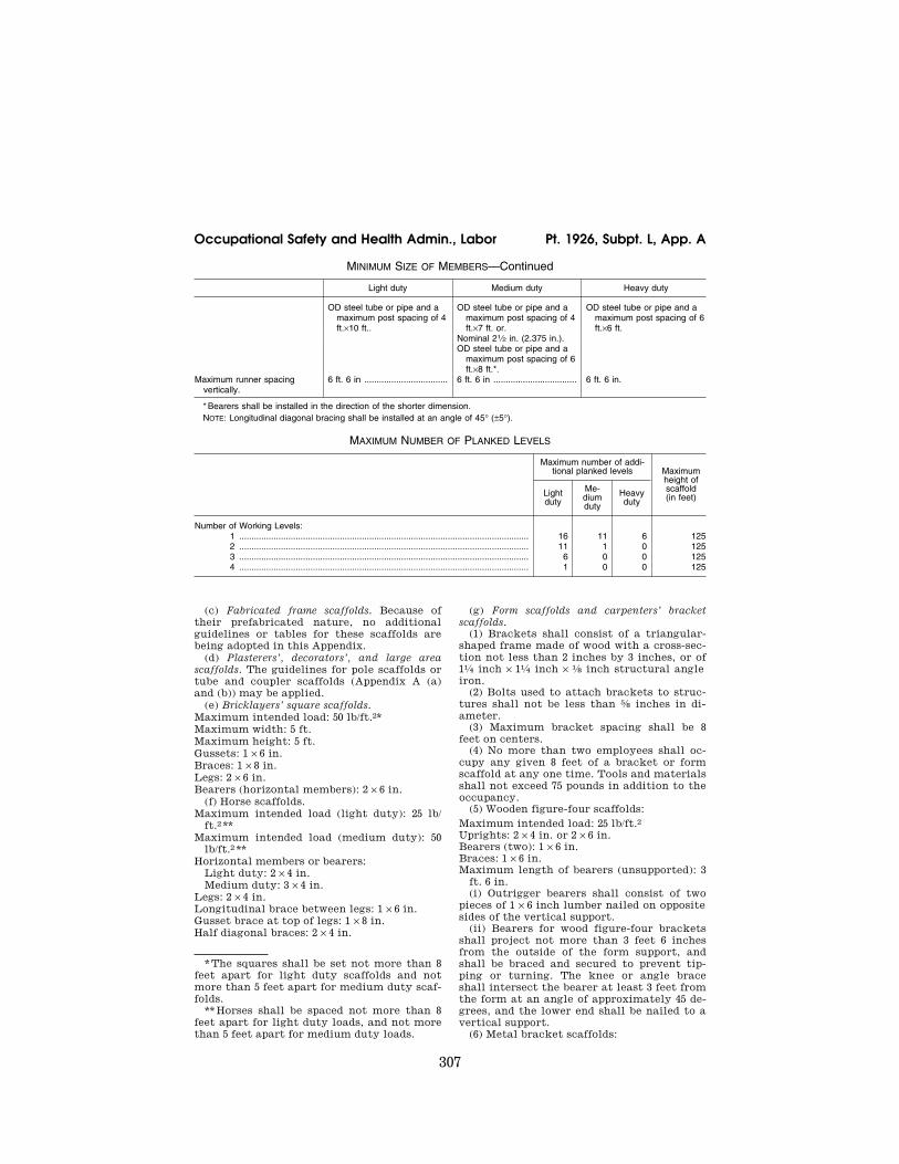
307
Occupational Safety and Health Admin., Labor Pt. 1926, Subpt. L, App. A
*The squares shall be set not more than 8 feet apart for light duty scaffolds and not more than 5 feet apart for medium duty scaf-folds.
**Horses shall be spaced not more than 8 feet apart for light duty loads, and not more than 5 feet apart for medium duty loads.
MINIMUM SIZE OF MEMBERS—Continued
Light duty Medium duty Heavy duty
OD steel tube or pipe and a maximum post spacing of 4 ft.×10 ft..
OD steel tube or pipe and a maximum post spacing of 4 ft.×7 ft. or.
OD steel tube or pipe and a maximum post spacing of 6 ft.×6 ft.
Nominal 21⁄2 in. (2.375 in.).OD steel tube or pipe and a
maximum post spacing of 6 ft.×8 ft.*.
Maximum runner spacing vertically.
6 ft. 6 in .................................. 6 ft. 6 in .................................. 6 ft. 6 in.
* Bearers shall be installed in the direction of the shorter dimension. NOTE: Longitudinal diagonal bracing shall be installed at an angle of 45° (±5°).
MAXIMUM NUMBER OF PLANKED LEVELS
Maximum number of addi-tional planked levels Maximum
height of scaffold (in feet) Light
duty
Me-dium duty
Heavy duty
Number of Working Levels: 1 ...................................................................................................................... 16 11 6 125 2 ...................................................................................................................... 11 1 0 125 3 ...................................................................................................................... 6 0 0 125 4 ...................................................................................................................... 1 0 0 125
(c) Fabricated frame scaffolds. Because of their prefabricated nature, no additional guidelines or tables for these scaffolds are being adopted in this Appendix.
(d) Plasterers’, decorators’, and large area scaffolds. The guidelines for pole scaffolds or tube and coupler scaffolds (Appendix A (a) and (b)) may be applied.
(e) Bricklayers’ square scaffolds. Maximum intended load: 50 lb/ft.2* Maximum width: 5 ft. Maximum height: 5 ft. Gussets: 1 × 6 in. Braces: 1 × 8 in. Legs: 2 × 6 in. Bearers (horizontal members): 2 × 6 in.
(f) Horse scaffolds. Maximum intended load (light duty): 25 lb/
ft.2 ** Maximum intended load (medium duty): 50
lb/ft.2 ** Horizontal members or bearers:
Light duty: 2 × 4 in. Medium duty: 3 × 4 in.
Legs: 2 × 4 in. Longitudinal brace between legs: 1 × 6 in. Gusset brace at top of legs: 1 × 8 in. Half diagonal braces: 2 × 4 in.
(g) Form scaffolds and carpenters’ bracket scaffolds.
(1) Brackets shall consist of a triangular- shaped frame made of wood with a cross-sec-tion not less than 2 inches by 3 inches, or of 11⁄4 inch × 11⁄4 inch × 1⁄8 inch structural angle iron.
(2) Bolts used to attach brackets to struc-tures shall not be less than 5⁄8 inches in di-ameter.
(3) Maximum bracket spacing shall be 8 feet on centers.
(4) No more than two employees shall oc-cupy any given 8 feet of a bracket or form scaffold at any one time. Tools and materials shall not exceed 75 pounds in addition to the occupancy.
(5) Wooden figure-four scaffolds: Maximum intended load: 25 lb/ft.2 Uprights: 2 × 4 in. or 2 × 6 in. Bearers (two): 1 × 6 in. Braces: 1 × 6 in. Maximum length of bearers (unsupported): 3
ft. 6 in. (i) Outrigger bearers shall consist of two
pieces of 1 × 6 inch lumber nailed on opposite sides of the vertical support.
(ii) Bearers for wood figure-four brackets shall project not more than 3 feet 6 inches from the outside of the form support, and shall be braced and secured to prevent tip-ping or turning. The knee or angle brace shall intersect the bearer at least 3 feet from the form at an angle of approximately 45 de-grees, and the lower end shall be nailed to a vertical support.
(6) Metal bracket scaffolds:
VerDate Mar<15>2010 15:51 Sep 16, 2011 Jkt 223116 PO 00000 Frm 00317 Fmt 8010 Sfmt 8002 Q:\29\29V8.TXT ofr150 PsN: PC150
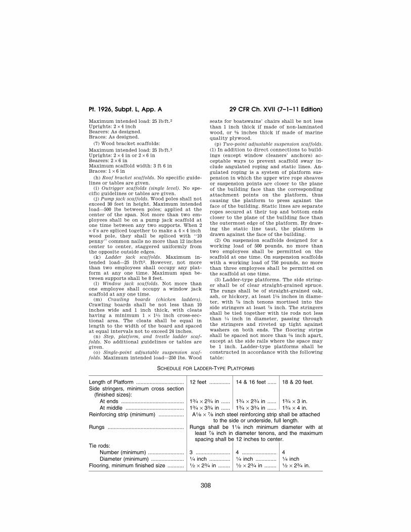
308
29 CFR Ch. XVII (7–1–11 Edition) Pt. 1926, Subpt. L, App. A
Maximum intended load: 25 lb/ft.2 Uprights: 2 × 4 inch Bearers: As designed. Braces: As designed.
(7) Wood bracket scaffolds: Maximum intended load: 25 lb/ft.2 Uprights: 2 × 4 in or 2 × 6 in Bearers: 2 × 6 in Maximum scaffold width: 3 ft 6 in Braces: 1 × 6 in
(h) Roof bracket scaffolds. No specific guide-lines or tables are given.
(i) Outrigger scaffolds (single level). No spe-cific guidelines or tables are given.
(j) Pump jack scaffolds. Wood poles shall not exceed 30 feet in height. Maximum intended load—500 lbs between poles; applied at the center of the span. Not more than two em-ployees shall be on a pump jack scaffold at one time between any two supports. When 2 × 4’s are spliced together to make a 4 × 4 inch wood pole, they shall be spliced with ‘‘10 penny’’ common nails no more than 12 inches center to center, staggered uniformly from the opposite outside edges.
(k) Ladder jack scaffolds. Maximum in-tended load—25 lb/ft2. However, not more than two employees shall occupy any plat-form at any one time. Maximum span be-tween supports shall be 8 feet.
(l) Window jack scaffolds. Not more than one employee shall occupy a window jack scaffold at any one time.
(m) Crawling boards (chicken ladders). Crawling boards shall be not less than 10 inches wide and 1 inch thick, with cleats having a minimum 1 × 11⁄2 inch cross-sec-tional area. The cleats shall be equal in length to the width of the board and spaced at equal intervals not to exceed 24 inches.
(n) Step, platform, and trestle ladder scaf-folds. No additional guidelines or tables are given.
(o) Single-point adjustable suspension scaf-folds. Maximum intended load—250 lbs. Wood
seats for boatswains’ chairs shall be not less than 1 inch thick if made of non-laminated wood, or 5⁄8 inches thick if made of marine quality plywood.
(p) Two-point adjustable suspension scaffolds. (1) In addition to direct connections to build-ings (except window cleaners’ anchors) ac-ceptable ways to prevent scaffold sway in-clude angulated roping and static lines. An-gulated roping is a system of platform sus-pension in which the upper wire rope sheaves or suspension points are closer to the plane of the building face than the corresponding attachment points on the platform, thus causing the platform to press against the face of the building. Static lines are separate ropes secured at their top and bottom ends closer to the plane of the building face than the outermost edge of the platform. By draw-ing the static line taut, the platform is drawn against the face of the building.
(2) On suspension scaffolds designed for a working load of 500 pounds, no more than two employees shall be permitted on the scaffold at one time. On suspension scaffolds with a working load of 750 pounds, no more than three employees shall be permitted on the scaffold at one time.
(3) Ladder-type platforms. The side string-er shall be of clear straight-grained spruce. The rungs shall be of straight-grained oak, ash, or hickory, at least 11⁄8 inches in diame-ter, with 7⁄8 inch tenons mortised into the side stringers at least 7⁄8 inch. The stringers shall be tied together with tie rods not less than 1⁄4 inch in diameter, passing through the stringers and riveted up tight against washers on both ends. The flooring strips shall be spaced not more than 5⁄8 inch apart, except at the side rails where the space may be 1 inch. Ladder-type platforms shall be constructed in accordance with the following table:
SCHEDULE FOR LADDER-TYPE PLATFORMS
Length of Platform ................................ 12 feet .............. 14 & 16 feet ...... 18 & 20 feet. Side stringers, minimum cross section
(finished sizes): At ends .......................................... 13⁄4 × 23⁄4 in ...... 13⁄4 × 23⁄4 in ...... 13⁄4 × 3 in. At middle ....................................... 13⁄4 × 33⁄4 in ...... 13⁄4 × 33⁄4 in ...... 13⁄4 × 4 in.
Reinforcing strip (minimum) ................. A1⁄8 × 7⁄8 inch steel reinforcing strip shall be attached to the side or underside, full length.
Rungs ................................................... Rungs shall be 11⁄8 inch minimum diameter with at least 7⁄8 inch in diameter tenons, and the maximum spacing shall be 12 inches to center.
Tie rods: Number (minimum) ........................ 3 ....................... 4 ....................... 4 Diameter (minimum) ...................... 1⁄4 inch .............. 1⁄4 inch .............. 1⁄4 inch
Flooring, minimum finished size ........... 1⁄2 × 23⁄4 in ........ 1⁄2 × 23⁄4 in ........ 1⁄2 × 23⁄4 in.
VerDate Mar<15>2010 15:51 Sep 16, 2011 Jkt 223116 PO 00000 Frm 00318 Fmt 8010 Sfmt 8002 Q:\29\29V8.TXT ofr150 PsN: PC150
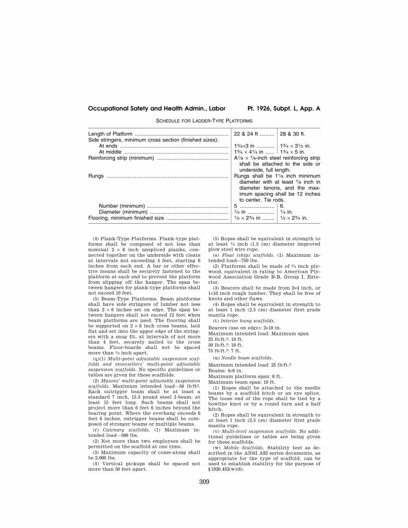
309
Occupational Safety and Health Admin., Labor Pt. 1926, Subpt. L, App. A
SCHEDULE FOR LADDER-TYPE PLATFORMS
Length of Platform ............................................................... 22 & 24 ft .......... 28 & 30 ft. Side stringers, minimum cross section (finished sizes):
At ends ......................................................................... 13⁄4×3 in ............ 13⁄4 × 31⁄2 in. At middle ...................................................................... 13⁄4 × 41⁄4 in ...... 13⁄4 × 5 in.
Reinforcing strip (minimum) ................................................ A1⁄8 × 7⁄8-inch steel reinforcing strip shall be attached to the side or underside, full length.
Rungs .................................................................................. Rungs shall be 11⁄8 inch minimum diameter with at least 7⁄8 inch in diameter tenons, and the max-imum spacing shall be 12 inches to center. Tie rods.
Number (minimum) ....................................................... 5 ....................... 6. Diameter (minimum) ..................................................... 1⁄4 in .................. 1⁄4 in.
Flooring, minimum finished size .......................................... 1⁄2 × 23⁄4 in ........ 1⁄2 × 23⁄4 in.
(4) Plank-Type Platforms. Plank-type plat-forms shall be composed of not less than nominal 2 × 8 inch unspliced planks, con-nected together on the underside with cleats at intervals not exceeding 4 feet, starting 6 inches from each end. A bar or other effec-tive means shall be securely fastened to the platform at each end to prevent the platform from slipping off the hanger. The span be-tween hangers for plank-type platforms shall not exceed 10 feet.
(5) Beam-Type Platforms. Beam platforms shall have side stringers of lumber not less than 2 × 6 inches set on edge. The span be-tween hangers shall not exceed 12 feet when beam platforms are used. The flooring shall be supported on 2 × 6 inch cross beams, laid flat and set into the upper edge of the string-ers with a snug fit, at intervals of not more than 4 feet, securely nailed to the cross beams. Floor-boards shall not be spaced more than 1⁄2 inch apart.
(q)(1) Multi-point adjustable suspension scaf-folds and stonesetters’ multi-point adjustable suspension scaffolds. No specific guidelines or tables are given for these scaffolds.
(2) Masons’ multi-point adjustable suspension scaffolds. Maximum intended load—50 lb/ft2. Each outrigger beam shall be at least a standard 7 inch, 15.3 pound steel I-beam, at least 15 feet long. Such beams shall not project more than 6 feet 6 inches beyond the bearing point. Where the overhang exceeds 6 feet 6 inches, outrigger beams shall be com-posed of stronger beams or multiple beams.
(r) Catenary scaffolds. (1) Maximum in-tended load—500 lbs.
(2) Not more than two employees shall be permitted on the scaffold at one time.
(3) Maximum capacity of come-along shall be 2,000 lbs.
(4) Vertical pickups shall be spaced not more than 50 feet apart.
(5) Ropes shall be equivalent in strength to at least 1⁄2 inch (1.3 cm) diameter improved plow steel wire rope.
(s) Float (ship) scaffolds. (1) Maximum in-tended load—750 lbs.
(2) Platforms shall be made of 3⁄4 inch ply-wood, equivalent in rating to American Ply-wood Association Grade B-B, Group I, Exte-rior.
(3) Bearers shall be made from 2×4 inch, or 1×10 inch rough lumber. They shall be free of knots and other flaws.
(4) Ropes shall be equivalent in strength to at least 1 inch (2.5 cm) diameter first grade manila rope.
(t) Interior hung scaffolds.
Bearers (use on edge): 2×10 in. Maximum intended load: Maximum span 25 lb/ft.2: 10 ft. 50 lb/ft.2: 10 ft. 75 lb/ft.2: 7 ft.
(u) Needle beam scaffolds.
Maximum intended load: 25 lb/ft.2 Beams: 4×6 in. Maximum platform span: 8 ft. Maximum beam span: 10 ft.
(1) Ropes shall be attached to the needle beams by a scaffold hitch or an eye splice. The loose end of the rope shall be tied by a bowline knot or by a round turn and a half hitch.
(2) Ropes shall be equivalent in strength to at least 1 inch (2.5 cm) diameter first grade manila rope.
(v) Multi-level suspension scaffolds. No addi-tional guidelines or tables are being given for these scaffolds.
(w) Mobile Scaffolds. Stability test as de-scribed in the ANSI A92 series documents, as appropriate for the type of scaffold, can be used to establish stability for the purpose of § 1926.452(w)(6).
VerDate Mar<15>2010 15:51 Sep 16, 2011 Jkt 223116 PO 00000 Frm 00319 Fmt 8010 Sfmt 8002 Q:\29\29V8.TXT ofr150 PsN: PC150
310
29 CFR Ch. XVII (7–1–11 Edition) Pt. 1926, Subpt. L, App. C
(x) Repair bracket scaffolds. No additional guidelines or tables are being given for these scaffolds.
(y) Stilts. No specific guidelines or tables are given.
(z) Tank builder’s scaffold. (1) The maximum distance between brack-
ets to which scaffolding and guardrail sup-ports are attached shall be no more than 10 feet 6 inches.
(2) Not more than three employees shall occupy a 10 feet 6 inch span of scaffold plank-ing at any time.
(3) A taut wire or synthetic rope supported on the scaffold brackets shall be installed at the scaffold plank level between the inner-most edge of the scaffold platform and the curved plate structure of the tank shell to serve as a safety line in lieu of an inner guardrail assembly where the space between the scaffold platform and the tank exceeds 12 inches (30.48 cm). In the event the open space on either side of the rope exceeds 12 inches (30.48 cm), a second wire or synthetic rope appropriately placed, or guardrails in ac-cordance with § 1926.451(e)(4), shall be in-stalled in order to reduce that open space to less than 12 inches (30.48 cm).
(4) Scaffold planks of rough full-dimen-sioned 2-inch (5.1 cm)×12-inch (30.5 cm) Doug-las Fir or Southern Yellow Pine of Select Structural Grade shall be used. Douglas Fir planks shall have a fiber stress of at least 1900 lb/in2 (130,929 n/cm2) and a modulus of elasticity of at least 1,900,000 lb/in2 (130,929,000 n/cm2), while Yellow Pine planks shall have a fiber stress of at least 2500 lb/in2 (172,275 n/cm2) and a modulus of elasticity of at least 2,000,000 lb/in2 (137,820,000 n/cm2).
(5) Guardrails shall be constructed of a taut wire or synthetic rope, and shall be sup-ported by angle irons attached to brackets welded to the steel plates. These guardrails shall comply with § 1926.451(e)(4). Guardrail supports shall be located at no greater than 10 feet 6 inch intervals.
(NON-MANDATORY) APPENDIX B TO SUB-PART L OF PART 1926—CRITERIA FOR DETERMINING THE FEASIBILITY OF PROVIDING SAFE ACCESS AND FALL PROTECTION FOR SCAFFOLD EREC-TORS AND DISMANTLERS [RE-SERVED]
(NON-MANDATORY) APPENDIX C TO SUB-PART L OF PART 1926—LIST OF NA-TIONAL CONSENSUS STANDARDS
ANSI/SIA A92.2–1990 Vehicle-Mounted Ele-vating and Rotating Aerial Devices
ANSI/SIA A92.3–1990 Manually Propelled Ele-vating Aerial Platforms
ANSI/SIA A92.5–1990 Boom Supported Ele-vating Work Platforms
ANSI/SIA A92.6–1990 Self-Propelled Elevating Work Platforms
ANSI/SIA A92.7–1990 Airline Ground Support Vehicle-Mounted Vertical Lift Devices
ANSI/SIA A92.8–1993 Vehicle-Mounted Bridge Inspection and Maintenance Devices
ANSI/SIA A92.9–1993 Mast-Climbing Work Platforms
(NON-MANDATORY) APPENDIX D TO SUB-PART L OF PART 1926—LIST OF TRAINING TOPICS FOR SCAFFOLD ERECTORS AND DISMANTLERS
This appendix D is provided to serve as a guide to assist employers when evaluating the training needs of employees erecting or dismantling supported scaffolds.
The Agency believes that employees erect-ing or dismantling scaffolds should be trained in the following topics: • General Overview of Scaffolding
• regulations and standards • erection/dismantling planning • PPE and proper procedures • fall protection • materials handling • access • working platforms • foundations • guys, ties and braces
• Tubular Welded Frame Scaffolds • specific regulations and standards • components • parts inspection • erection/dismantling planning • guys, ties and braces • fall protection • general safety • access and platforms • erection/dismantling procedures • rolling scaffold assembly • putlogs
• Tube and Clamp Scaffolds • specific regulations and standards • components • parts inspection • erection/dismantling planning • guys, ties and braces • fall protection • general safety • access and platforms • erection/dismantling procedures • buttresses, cantilevers, & bridges
• System Scaffolds • specific regulations and standards • components • parts inspection • erection/dismantling planning • guys, ties and braces • fall protection • general safety • access and platforms • erection/dismantling procedures • buttresses, cantilevers, & bridges
VerDate Mar<15>2010 15:51 Sep 16, 2011 Jkt 223116 PO 00000 Frm 00320 Fmt 8010 Sfmt 8002 Q:\29\29V8.TXT ofr150 PsN: PC150
311
Occupational Safety and Health Admin., Labor Pt. 1926, Subpt. L, App. E
Scaffold erectors and dismantlers should all receive the general overview, and, in ad-
dition, specific training for the type of sup-ported scaffold being erected or dismantled.
(NON-MANDATORY) APPENDIX E TO SUBPART L OF PART 1926—DRAWINGS AND ILLUSTRATIONS
This appendix provides drawings of particular types of scaffolds and scaffold components, and graphic illustrations of bracing patterns and tie spacing patterns.
This appendix is intended to provide visual guidance to assist the user in complying with the requirements of subpart L, part 1926.
VerDate Mar<15>2010 15:51 Sep 16, 2011 Jkt 223116 PO 00000 Frm 00321 Fmt 8010 Sfmt 8026 Q:\29\29V8.TXT ofr150 PsN: PC150
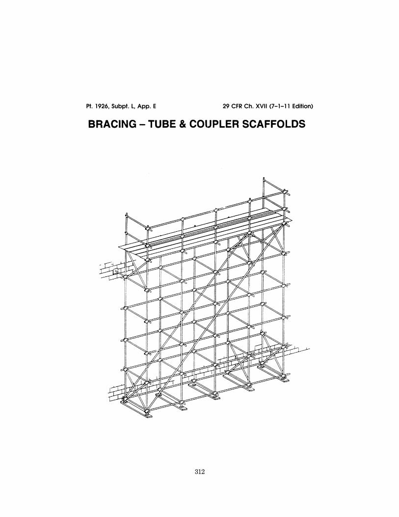
312
29 CFR Ch. XVII (7–1–11 Edition) Pt. 1926, Subpt. L, App. E
VerDate Mar<15>2010 15:51 Sep 16, 2011 Jkt 223116 PO 00000 Frm 00322 Fmt 8010 Sfmt 8006 Q:\29\29V8.TXT ofr150 PsN: PC150 ER
30au
96.0
00<
/GP
H>
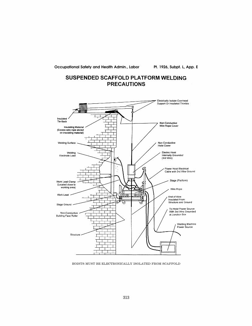
313
Occupational Safety and Health Admin., Labor Pt. 1926, Subpt. L, App. E
HOISTS MUST BE ELECTRONICALLY ISOLATED FROM SCAFFOLD
VerDate Mar<15>2010 15:51 Sep 16, 2011 Jkt 223116 PO 00000 Frm 00323 Fmt 8010 Sfmt 8006 Q:\29\29V8.TXT ofr150 PsN: PC150 ER
30au
96.0
01
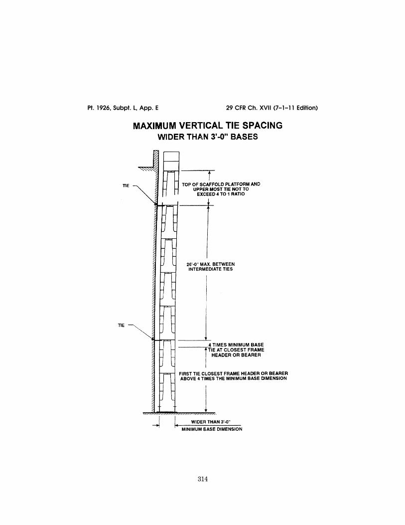
314
29 CFR Ch. XVII (7–1–11 Edition) Pt. 1926, Subpt. L, App. E
VerDate Mar<15>2010 15:51 Sep 16, 2011 Jkt 223116 PO 00000 Frm 00324 Fmt 8010 Sfmt 8006 Q:\29\29V8.TXT ofr150 PsN: PC150 ER
30au
96.0
02<
/GP
H>
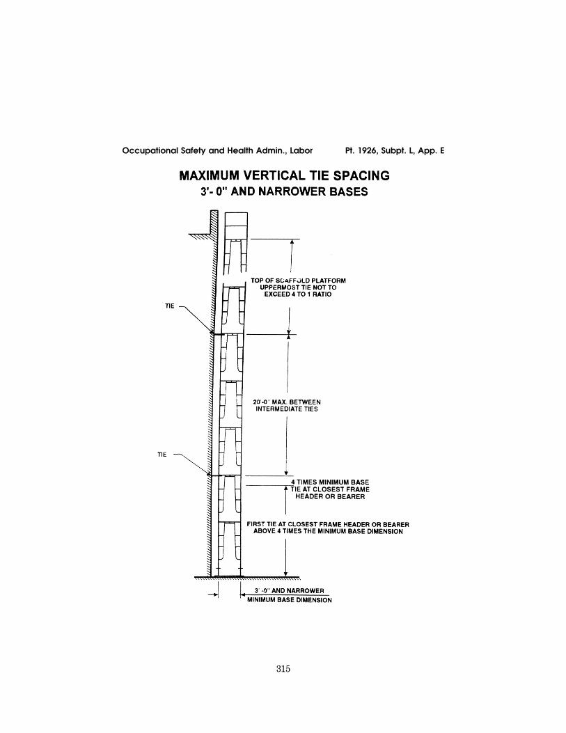
315
Occupational Safety and Health Admin., Labor Pt. 1926, Subpt. L, App. E
VerDate Mar<15>2010 15:51 Sep 16, 2011 Jkt 223116 PO 00000 Frm 00325 Fmt 8010 Sfmt 8006 Q:\29\29V8.TXT ofr150 PsN: PC150 ER
30au
96.0
03<
/GP
H>
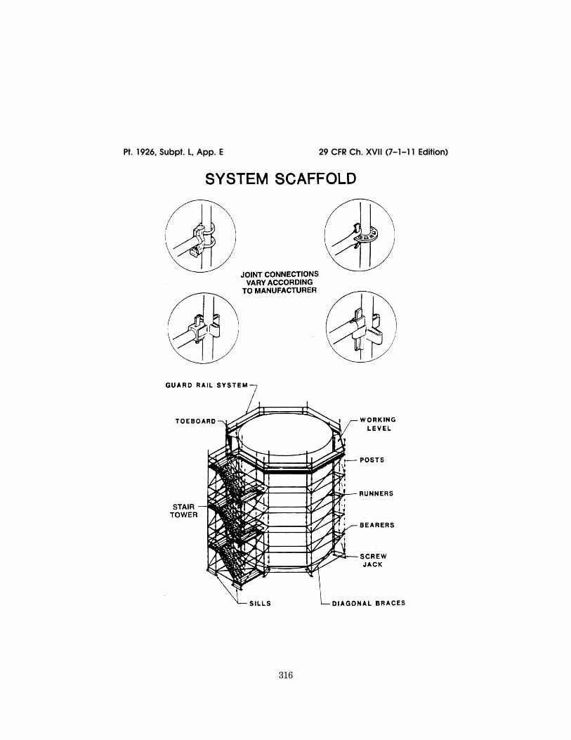
316
29 CFR Ch. XVII (7–1–11 Edition) Pt. 1926, Subpt. L, App. E
VerDate Mar<15>2010 15:51 Sep 16, 2011 Jkt 223116 PO 00000 Frm 00326 Fmt 8010 Sfmt 8006 Q:\29\29V8.TXT ofr150 PsN: PC150 ER
30au
96.0
04<
/GP
H>
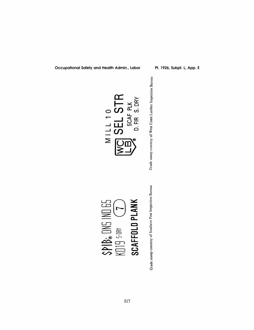
317
Occupational Safety and Health Admin., Labor Pt. 1926, Subpt. L, App. E
VerDate Mar<15>2010 15:51 Sep 16, 2011 Jkt 223116 PO 00000 Frm 00327 Fmt 8010 Sfmt 8006 Q:\29\29V8.TXT ofr150 PsN: PC150 ER
30au
96.0
05<
/GP
H>
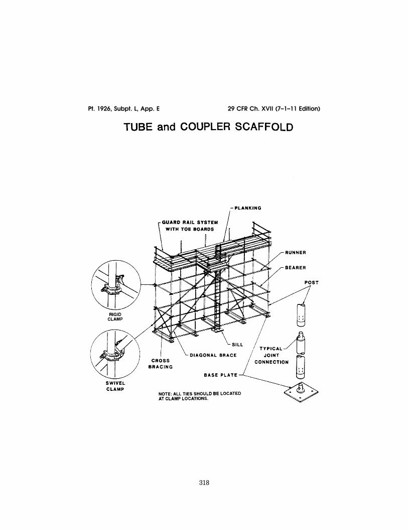
318
29 CFR Ch. XVII (7–1–11 Edition) Pt. 1926, Subpt. L, App. E
VerDate Mar<15>2010 15:51 Sep 16, 2011 Jkt 223116 PO 00000 Frm 00328 Fmt 8010 Sfmt 8006 Q:\29\29V8.TXT ofr150 PsN: PC150 ER
30au
96.0
06<
/GP
H>
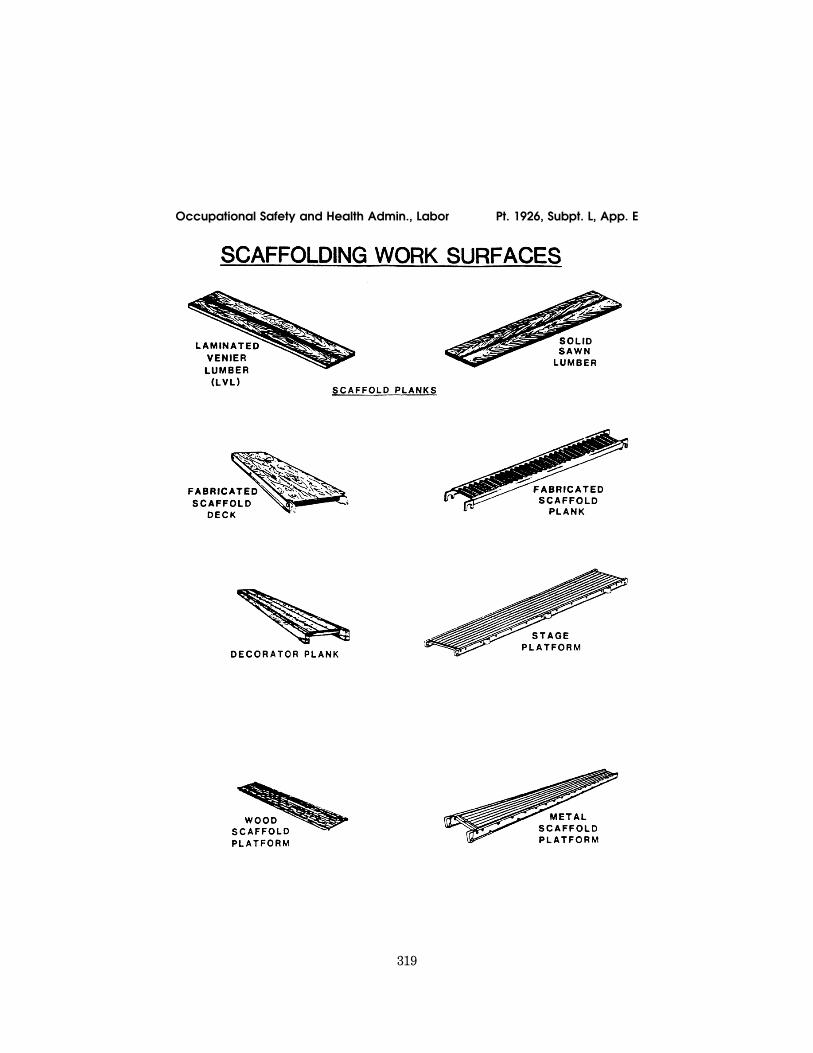
319
Occupational Safety and Health Admin., Labor Pt. 1926, Subpt. L, App. E
VerDate Mar<15>2010 15:51 Sep 16, 2011 Jkt 223116 PO 00000 Frm 00329 Fmt 8010 Sfmt 8006 Q:\29\29V8.TXT ofr150 PsN: PC150 ER
30au
96.0
07<
/GP
H>
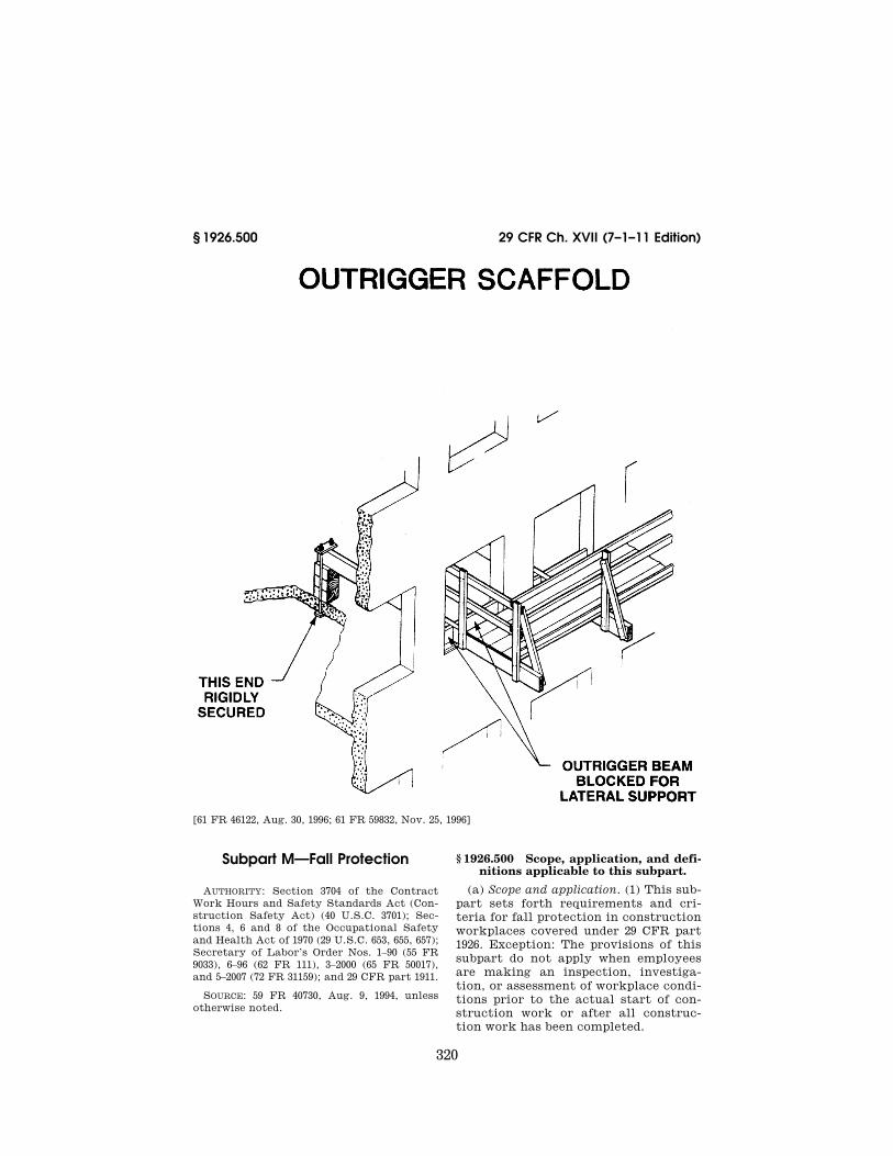
320
29 CFR Ch. XVII (7–1–11 Edition) § 1926.500
[61 FR 46122, Aug. 30, 1996; 61 FR 59832, Nov. 25, 1996]
Subpart M—Fall Protection
AUTHORITY: Section 3704 of the Contract Work Hours and Safety Standards Act (Con-struction Safety Act) (40 U.S.C. 3701); Sec-tions 4, 6 and 8 of the Occupational Safety and Health Act of 1970 (29 U.S.C. 653, 655, 657); Secretary of Labor’s Order Nos. 1–90 (55 FR 9033), 6–96 (62 FR 111), 3–2000 (65 FR 50017), and 5–2007 (72 FR 31159); and 29 CFR part 1911.
SOURCE: 59 FR 40730, Aug. 9, 1994, unless otherwise noted.
§ 1926.500 Scope, application, and defi-nitions applicable to this subpart.
(a) Scope and application. (1) This sub-part sets forth requirements and cri-teria for fall protection in construction workplaces covered under 29 CFR part 1926. Exception: The provisions of this subpart do not apply when employees are making an inspection, investiga-tion, or assessment of workplace condi-tions prior to the actual start of con-struction work or after all construc-tion work has been completed.
VerDate Mar<15>2010 15:51 Sep 16, 2011 Jkt 223116 PO 00000 Frm 00330 Fmt 8010 Sfmt 8002 Q:\29\29V8.TXT ofr150 PsN: PC150 ER
30au
96.0
08<
/GP
H>