study report 05 / 02 / 2010 dvm-10-102957-08343b
TRANSCRIPT

STUDY REPORT 05 / 02 / 2010
DVM-10-102957-08343B
DRA71 – Operation A4 - DRA73 – Operation C2.1
Industrial installation ageing management
Refinery piping benchmark


Ref.: DVM-10-102957-08343B Page 1 of 69
DRA 71 - Operation A1.2 - DRA 73 - Operation C2.1
Industrial installation ageing management Refinery piping benchmark
Verneuil-en-Halatte (60)

Ref.: DVM-10-102957-08343B Page 2 of 69
FOREWORD
This report was produced on the basis of information provided to INERIS, of available and objective data (whether scientific or technical) and applicable regulations.
INERIS cannot be held liable if the information provided was incomplete or erroneous.
The opinions, recommendations, advice or equivalent that may be offered by INERIS as part of the services entrusted to it, may assist in decision making. Given the mission entrusted to INERIS by the decree creating it, INERIS does not take part in any actual decision making. INERIS cannot therefore take the decision maker’s place.
The addressee shall use the results included in this report in full or at least in an objective way. Any use of the report in the form of excerpts or summary memos will be performed under the addressee’s sole and exclusive responsibility. The same applies to any modification made to it.
INERIS declines any liability for any use of the report outside of the scope of this service.
The present study report written in English is for information only. The French version shall prevail over any translation.
Written by Reviewed by Checked by Approved by
Name Olivier
DOLLADILLE
Valérie DE DIANOUS
Frédéric MERLIER
Marie-Astrid SOENEN
Sylvain CHAUMETTE
Yann MACÉ
Title
Engineer Risk
Management Advisory Unit
(MHSE) Valorisation &
Marketing
Engineer Quantitative
Risk Evaluation Unit (EQRI)
Manager, DIAG Unit
Accidental Risks Division
Administration Support Delegate
Accidental Risks Division
Manager AGIR Unit Accidental
Risks Division
Director Accidental
Risks Division
Signatures

Ref.: DVM-10-102957-08343B Page 3 of 69
TABLE OF CONTENTS
1. INTRODUCTION – STUDY CONTEXT ............................................................ 9
1.1 Context .......................................................................................................... 9
1.2 Study Scope ................................................................................................ 10
1.3 Report Organisation .................................................................................... 11
2. ACCIDENT REVIEW ...................................................................................... 13
2.1 Foreword ..................................................................................................... 13
2.2 Accidents Outside of France ....................................................................... 14
2.2.1 Martinez, California (USA), February 23rd 1999 (3) (4) ........................... 14
2.2.1.1 Sequence of Events .......................................................................... 15
2.2.1.2 Causes of the Accident ..................................................................... 17
2.2.2 Grangemouth (Scotland), 10 June 2000 .................................................. 20
2.2.2.1 Sequence of Events .......................................................................... 20
2.2.2.2 Causes of the Accident ..................................................................... 22
2.2.3 Humber (U.K.), 16 April 2001 (8) (9) ........................................................ 24
2.2.3.1 Sequence of Events .......................................................................... 24
2.2.3.2 Causes of the Accident ..................................................................... 26
2.2.3.3 Alert and Past Incidents .................................................................... 27
2.2.3.4 Corrosion and Inspection Management ............................................. 27
2.2.3.5 Management of Change .................................................................... 28
2.3 Recent Accidents in France ........................................................................ 29
2.3.1 Donges (44), 16 March 2008 (11) (12) .................................................... 29
2.3.2 Notre-Dame de Gravenchon (76), 2008 (13) (14) .................................... 30
2.4 Lessons Learnt ............................................................................................ 32
3. APPLIED MONITORING POLICIES............................................................... 33
3.1 Regulations and Guidelines ........................................................................ 33

Ref.: DVM-10-102957-08343B Page 4 of 69
3.1.1 Pressure Equipment (PE) Regulations in France ..................................... 33
3.1.1.1 Piping Submission Thresholds .......................................................... 33
3.1.1.2 Recognised Inspection Department (RID) ......................................... 34
3.1.2 Guidelines ................................................................................................ 34
3.1.3 Field Application ....................................................................................... 35
3.2 Elaborating and Implementing Inspection Plans ......................................... 36
3.2.1 Piping Condition Description .................................................................... 36
3.2.2 Degradation Mechanisms ........................................................................ 36
3.2.3 Evaluating the Criticality and Defining Control Methods .......................... 37
3.2.4 Key Elements in the RBI Process ............................................................ 39
4. PIPING INSPECTION DIFFICULTIES ........................................................... 41
4.1 Presence of Insulation ................................................................................ 41
4.2 Piping Environment Issues ......................................................................... 43
4.2.1 Main Configurations Causing Hindrance .................................................. 43
4.2.1.1 Racks ................................................................................................ 44
4.2.1.2 Off-site Pipeways ............................................................................... 45
4.2.2 Pipe Penetration Through Sleeves and Bund Walls ................................ 46
4.3 Operating Condition Issues ........................................................................ 47
4.4 Expansion Compensators .......................................................................... 47
5. SERVICE LIFE AND REMAINING LIFE CONCEPTS ................................... 49
5.1 Service Life ................................................................................................. 49
5.2 Measuring Pipe Thickness ......................................................................... 50
5.2.1 Thickness Measurement Locations .......................................................... 50
5.2.2 Methods Applied ...................................................................................... 52
5.3 Determining Corrosion Rates ..................................................................... 52
5.4 Remaining Life and Next Check Deadlines ................................................ 53
5.5 Maintaining Piping In Service ..................................................................... 55

Ref.: DVM-10-102957-08343B Page 5 of 69
6. CORROSION MANAGEMENT ....................................................................... 57
6.1 Goals ........................................................................................................... 57
6.2 Cost in Refinery Sector ............................................................................... 57
6.3 Example of Corrosion Management on an Atmospheric Distillation Unit..... 58
6.3.1 Desalting of Crude Oil .............................................................................. 58
6.3.2 Protection Against Corrosion by High Temperature Sulphur ................... 59
6.3.3 Protection Against Corrosion by Naphthenic Acid ................................... 59
6.3.4 Measurement Overview ........................................................................... 60
6.4 Impact of Crude Oil Quality on Corrosion Management .............................. 60
7. CONCLUSION ................................................................................................ 63
8. BIBLIOGRAPHY ............................................................................................ 67
9. LIST OF ANNEXES ........................................................................................ 69


Ref.: DVM-10-102957-08343B Page 7 of 69
GLOSSARY
AFIAP : Association Française des Ingénieurs en Appareil à Pression (French Association of Pressure Equipment Engineers)
API : American Petroleum Institute
AR : Atmospheric Residue
BARPI : Bureau d’Analyse des Risques et Pollutions Industrielles(Bureau for risk analysis and industrial pollution of the French Ministry of Ecology, Energy, sustainable Development and Land Use Planning)
BSEI : Bureau de la Securite des Equipments Industriels(Bureau for the safety of industrial equipment)
COCL : Conditions Opératoires Critiques Limites (Critical Operating Condition Limits)
CSB : Chemical Safety and Hazard Investigation Board
CT : Short term (“Court Terme” in French)
CTNIIC : Comité Technique National de l’Inspection dans l’Industrie Chimique (National technical committee for inspection in the chemical industry)
CUI : Corrosion Under Insulation
DA : Atmospheric Distillation
DFO : Domestic Fuel Oil
DN : Nominal diameter
EFC : European Federation of Corrosion
ESSV : Equipement Soumis à Surveillance Volontaire (Equipment subject to voluntary monitoring)
FCC : Fluid Catalytic Cracking
FFS : Fitness For Service
GEMER : Groupement d'Étude des Matériaux en Raffinerie(Group for refinery material studies)

Ref.: DVM-10-102957-08343B Page 8 of 69
HCO : Heavy Cycle Oil
HSE : Health and Safety Executive
HSL : Health and Safety Laboratory
LCO : Light Cycle Oil
LPG : Liquid Petroleum Gas
LT : Long Term
NAC : Naphtenic Acid Corrosion
NDT : Non-Destructive Testing
OSHA : Occupational Safety and Health Administration
PI : Periodic inspection
PR : Periodic Requalification
PSM : Process Safety Management
RBI : Risk-Based Inspection
RID : Recognised Inspection Department
SMS : Safety Management System
TAN : Total Acid Number
TI : Temperature Indicator
TML : Thickness Measurement Location
UFIP : Union Française des Industries Pétrolières (French oil industry association)
UIC : Union des Industries Chimiques (French chemical industry association)
VD : Vacuum Distillation
VGO : Vacuum Gas Oil

Ref.: DVM-10-102957-08343B Page 9 of 69
1. INTRODUCTION – STUDY CONTEXT
1.1 CONTEXT
Considering the incidents and accidents that have occurred over the past years at French industrial installations, the French Ministry of Ecology, Energy, Sustainable Development and Territorial Development (MEEDDAT) launched, through a memo dated December 12th 20081, an action plan on managing industrial installation ageing as part of the prevention of technological hazards.
As stated in this memo, “All equipment and installations liable to lead to a technological hazard may be covered by actions as part of this plan, whether the equipment and the installations contain hazardous or polluting products” or “whether they form a safety mechanism by their design (e.g. a firewall), whether they play a part in compensating for deviations (e.g. retention, alert or intervention systems) or whether they play a part in safety management (e.g. command and control systems). Any salient point will receive especially significant attention as part of this plan”.
Discussions took place in working groups (WGs) that gathered competent authorities, experts and industrial operators. The working group themes are listed below, the last four being dedicated to industrial installation ageing:
flammable liquid regulations,
pipelines,
piping and vessels,
electricity and instrumentation,
storage tanks,
civil works.
Furthermore, in its memo dated 11 February 20092, MEEDDAT detailed how INERIS would contribute to the action plan on ageing management (refer to Annex B to the General Benchmark).
This report relates to the specific study of ageing management in refinery piping. It is based on a comparison between the regulation and standards applied in France and abroad, as regards ageing management (testing and inspection of equipment, qualified bodies to perform these inspections, etc.).
1 Memo BRTICP 2008-601-CBO dated 12 December 2008
2 Memo BRTICP 2009-46/OA dated 11 February 2009

Ref.: DVM-10-102957-08343B Page 10 of 69
Some issues such as regulations or professional guidelines recognised by the competent authorities have deliberately not been expanded on. For further details, readers are invited to refer to the general report on ageing management, referenced as INERIS- DRA-09-102957-07985C.
The information provided in this report is taken from:
a literature review of regulatory documents, professional guidelines and works regarding inspection and ageing management approaches for industrial installations,
information on practices applied as collected during refinery visits (see Annex A),
exchanges with expert entities (CETIM, French Institut de Soudure, Bureau Veritas, etc.) and discussions within the working groups set up by the Ministry on the theme of ageing.
Outside of France, the regulatory context in the United Kingdom, Germany, the Netherlands and the United States related to pressure equipment is presented in the general report mentioned above and is therefore not addressed in this document. The accident review section describes three events that happened in England, Scotland and in the United States. The American Petroleum Institute guidelines regarding the RBI method and other reports that are specific to pipe inspection have been taken into consideration. Finally, the survey undertaken in collaboration with EU-VRI in the four countries covered by the study, namely the United States, the United Kingdom, the Netherlands and Germany, did not identify specific practices relevant to refineries.
This report presents a fairly wide panorama, yet does not guarantee that the sources of information or the observed field practices are exhaustive.
1.2 STUDY SCOPE
In accordance with the assignment received by INERIS, this report only covers steel piping in refineries (both internal and external to the units) used to carry liquid or gaseous hydrocarbons.
The following were considered:
Piping within the unit that is or is not within the scope covered by regulations regarding pressure equipment,
Off-site3 piping that is or is not within the scope covered by regulations regarding pressure equipment.
Piping dedicated to utilities is not covered by this report.
3 Piping located outside of the plot (battery) boundaries.

Ref.: DVM-10-102957-08343B Page 11 of 69
INERIS’ mission letter also describes the products to be taken into account in the benchmark, namely the following toxic and flammable substances in liquid, gaseous or liquefied gas forms: hydrofluoric acid, hydrogen sulphide, gasoline, diesel oil, DFO, butane and propane.
This report makes no distinction between these products. It can be extended to all petroleum products carried by pipes within plants and off-site.
1.3 REPORT ORGANISATION
This report is divided into five main chapters:
Accident review: This chapter presents a number of recent accidents that occurred in France and abroad and that are, in part, the result of poor degradation management and/or inspection shortcomings.
Applied monitoring policies: This chapter presents regulations and guidelines to be used by refineries and then describes the main steps to elaborate a proper piping inspection plan.
Piping inspection difficulties: This chapter details specific difficulties involved in inspecting piping.
Service life and remaining life concepts: This chapter presents the approach applied by refineries to anticipate any changes to piping that could lead to reduced thickness.
Corrosion management: This chapter presents an example of actions taken by refineries to reduce corrosion in an atmospheric distillation unit and the related costs.
Annex A includes a summary of the exchanges that occurred during visits to six French refineries.


Ref.: DVM-10-102957-08343B Page 13 of 69
2. ACCIDENT REVIEW
2.1 FOREWORD
In refineries, piping is used everywhere. While its total length varies from one site to another, depending especially on the site’s organisation, the number of units or production capacity, there are usually several thousands of kilometres of pipes (excluding utilities), of which a significant proportion are difficult to access or see (pipes covered with insulation, mounted high up or on a rack, passing under roads or through bund walls…). These pipes form a very complex assembly that:
Connects the various equipment components within the units,
Connects units,
Connects to storage facilities,
Collects gaseous effluents and routes them to the flares,
Collects and distributes fuel gas,
Distributes utilities,
etc.
Therefore, to fulfil all of these functions a very wide variety of piping is needed, especially regarding their cross sections (less than 1” for instrumentation taps and up to 30” for atmospheric distillation head lines or flare collectors), their thicknesses or even the quality of their component materials even if carbon steels are most often used.
Piping characteristics are defined by the operating constraints, such as:
internal pressure (vacuum piping at the vacuum distillation unit, for pressures of up to 200 bars in some hydroconversion units),
temperature (strongly negative, from -140°C to -100°C at the demethaniser on a steam cracker, up to 500°C on the outlet of some conversion reactors),
state and properties of the products carried (the corrosive nature of hydrogen sulphide or hydrofluoric acid for example, the tendency of hydrogen to cause brittleness in stainless steel, etc.),
vibration phenomena,
etc.

Ref.: DVM-10-102957-08343B Page 14 of 69
This omnipresence and wide diversity mean that of all equipment, piping is the main cause of any loss of containment of hazardous substances (1). Given the flammable nature of hydrocarbons, and the operating conditions of the units, even with limited flow terms, piping is very often the triggering cause of accidents in refineries. In practice, the accident figures show that a failure of a small diameter branch pipe or a small breach, following by the leak catching fire may quickly have a domino effect that leads to the failure of vulnerable equipment like pipe networks of air cooled heat exchangers, isolated lines or ones that do not move and which will release larger amounts of hydrocarbons. These will then contribute to feed the fire which will see its amplitude and/or intensity increased. In the end, the resulting damage may turn out to be major. For example, such a sequence of events was observed in September 2000, in a catalytic cracker (2) where the failure of a ¾” branch caused major material damage and a shutdown of the unit for almost seven months.
The study of accidents caused by ageing pipes as performed by INERIS can be broken down into three parts:
a statistical analysis (for all kinds of equipment) based on the results of searches within the BARPI ARIA database,
a detailed presentation of three relevant accidents having occurred at refineries outside of France:
o Tosco Avon refinery in Martinez (USA), on February 23rd 1999,
o BP Grangemouth refinery (Scotland), on June 10th 2000,
o ConocoPhillips Humberside refinery (England), on April 16th 2001,
a shorter presentation of accidents having occurred recently at French refineries:
o Donges (Loire-Atlantique), March 16th 2008,
o Notre-Dame-de-Gravenchon (Seine-Maritime), September 6th 2008.
For the statistical analysis, readers are invited to refer to the general report on installation ageing referenced INERIS- DRA-09-102957-07985C dated December 31st 2009.
2.2 ACCIDENTS OUTSIDE OF FRANCE
2.2.1 Martinez, California (USA), February 23rd 1999 (3) (4)
On February 23rd 1999, a fire broke out in the atmospheric distillation unit at the Tosco Avon refinery in Martinez. The accident occurred during operations in order to replace the line linking the column (or fractionators) to the naphtha stripper. The column was engulfed in flames and four operators on the scaffolding, including three contractors and a refinery maintenance department operator, were killed. A fifth person was seriously injured.

Ref.: DVM-10-102957-08343B Page 15 of 69
The atmospheric distillation unit was built in 1946 and had been revamped on a number of occasions since then.
2.2.1.1 Sequence of Events
On February 10th, while distillation was operating normally, a small leak was detected on the 6” line linking the distillation column to the naphtha stripper. The decision was made to isolate the line by closing valves A, B, C and E as shown in Figure 1 below.
After removing the insulation from the line, a 4 mm hole was found inside the elbow located close to the column cut off valve (A), 34 metres above ground. Ultrasonic and X-ray tests showed that most of the line was severely corroded and thin. The technical team therefore proposed to replace the entire line. Nevertheless, the lack of any cut off valve at the stripper meant that it was impossible to do so without shutting down the unit. Consequently, the decision was made to change only the section between the valve (A) and the control valve (D), without stopping the process.
Figure 1: Simplified diagram of the link between the atmospheric distillation column and the
naphtha stripper. [Source (4)]
Ref.: DVM-10-102957-08343B Page 16 of 69
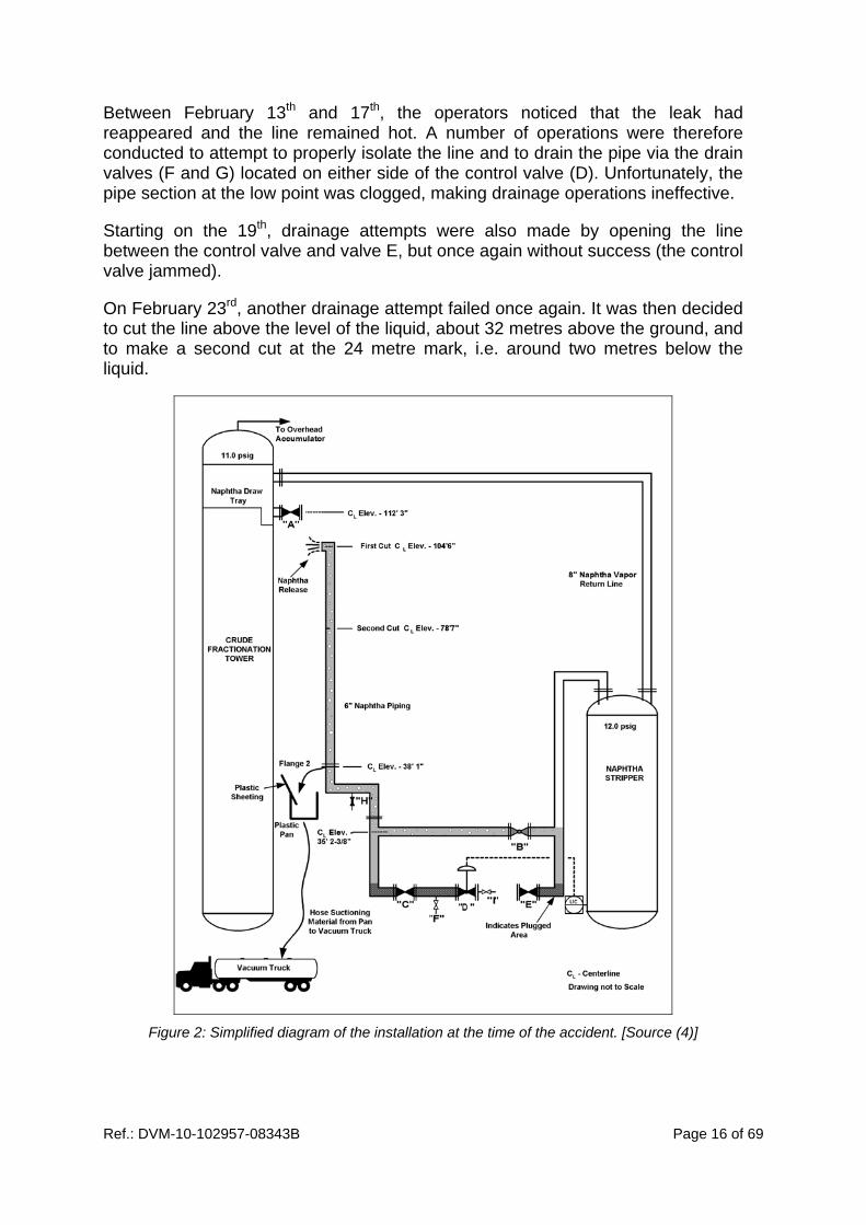
Between February 13th and 17th, the operators noticed that the leak had reappeared and the line remained hot. A number of operations were therefore conducted to attempt to properly isolate the line and to drain the pipe via the drain valves (F and G) located on either side of the control valve (D). Unfortunately, the pipe section at the low point was clogged, making drainage operations ineffective.
Starting on the 19th, drainage attempts were also made by opening the line between the control valve and valve E, but once again without success (the control valve jammed).
On February 23rd, another drainage attempt failed once again. It was then decided to cut the line above the level of the liquid, about 32 metres above the ground, and to make a second cut at the 24 metre mark, i.e. around two metres below the liquid.
Figure 2: Simplified diagram of the installation at the time of the accident. [Source (4)]

Ref.: DVM-10-102957-08343B Page 17 of 69
When the operator started the second cut, the naphtha started to run out. Consequently, the operator stopped the operation and attempted to stop the leak. The maintenance manager then decided to make another attempt to drain the line by slacking off the flange located 11.5 metres above the ground (i.e. only one metre above valve B) and to recover the naphtha in an open pan.
Before draining the line, the naphtha column height compensated for the process pressure caused by leaking valve B by functioning as a seal. Opening flange 2 at the low point lowered the liquid level, causing the loss of the pressure balance. The result was a sudden release of naphtha into the atmosphere, via the opening in the line located 32 metres above ground. The cloud that formed engulfed the column and caught fire on contact with the column base that was operating at a temperature level exceeding naphtha’s self-ignition temperature. The column and staff located on the scaffolding were surrounded by the fireball.
2.2.1.2 Causes of the Accident
The analysis undertaken by CSB identified a number of causes, especially in terms of:
the work schedule,
hazard identification and risk assessment,
decision-making regarding unit shutdown,
the definition of responsibilities,
work authorisations and procedures for opening the line,
corrosion checks,
change management.
It appears that the last two points were closely related and caused the accident.
Causes of the corrosion Salt removal from crude oil is an essential refinery operation as it conditions how “downstream” units will operate (5). This is because poor salt removal has direct consequences on the way the atmospheric distillation column operates:
increasing fouling in the preheating heat exchangers and furnace,
causing overhead circuit corrosion,
obtaining a sodium laden atmospheric residue with consequences on “downstream” units (vacuum distillation, viscoreducer, catalytic cracking, etc.).
The desalter located ahead of the distillation column is therefore designed to eliminate water and salt (sodium chloride and alkaline-earth content) contained in the crude oil, before fractionation.

Ref.: DVM-10-102957-08343B Page 18 of 69
In 1998, the Tosco Avon refinery started handling heavier crude oils, changing from an API 27.2° density to 23.7° or more. These crudes require a change in operating procedures as it becomes harder to separate water and to eliminate salt.
Two in-house reports published the same year raised issues related to this change:
On one hand, insufficient water elimination from the crude oil,
On the other hand, an increase in the corrosion risk, in particular at the column overhead and in the naphtha processing system, when heavy oils are refined (18° API).
Numerous desalter malfunctions were observed during 1998 and its performance deteriorated considerably. In November, a number of improvements were made to attempt to solve the problems (placing the unit’s desalter in parallel with that used by another unit, using new technologies). No additional measure was however taken to improve the inspection plans to avoid line plugging or to limit corrosion in the unit.
The desalter’s recurring malfunctions aggravated the corrosion phenomena in the unit, and contributed to the sequence of events due to:
the piercing of the pipe linking the distillation column and the naphtha stripper, inside the first elbow, causing the initial containment breach,
the internal degradation and significant thinning of most of the linking pipes, causing them to need replaced,
plugging of the portion of the line located at the low point on either side of the control valve and requiring the by-pass valve to be partially opened to compensate for the loss of flow during the ten months prior to the accident and inhibiting line draining prior to replacement,
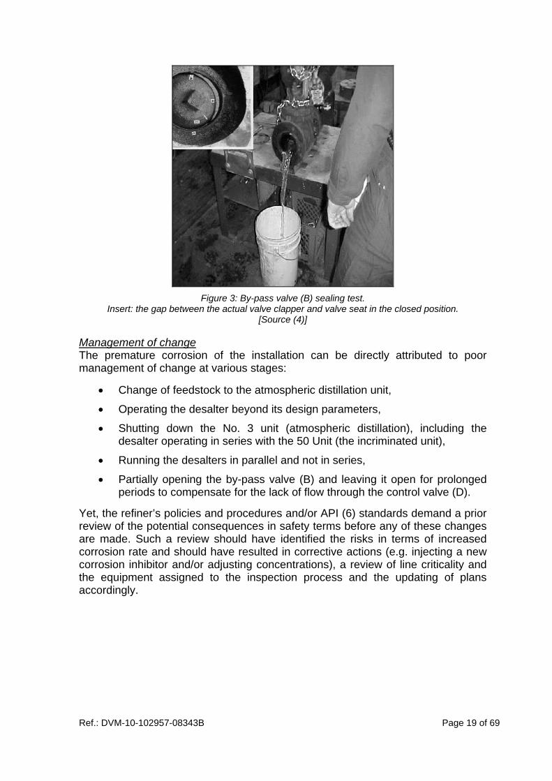
damage to the valve B seat and clapper on the by-pass line (due to erosion and corrosion) so that the stripper could not be cut off.
Ref.: DVM-10-102957-08343B Page 19 of 69
Figure 3: By-pass valve (B) sealing test.
Insert: the gap between the actual valve clapper and valve seat in the closed position. [Source (4)]
Management of change The premature corrosion of the installation can be directly attributed to poor management of change at various stages:
Change of feedstock to the atmospheric distillation unit,
Operating the desalter beyond its design parameters,
Shutting down the No. 3 unit (atmospheric distillation), including the desalter operating in series with the 50 Unit (the incriminated unit),
Running the desalters in parallel and not in series,
Partially opening the by-pass valve (B) and leaving it open for prolonged periods to compensate for the lack of flow through the control valve (D).
Yet, the refiner’s policies and procedures and/or API (6) standards demand a prior review of the potential consequences in safety terms before any of these changes are made. Such a review should have identified the risks in terms of increased corrosion rate and should have resulted in corrective actions (e.g. injecting a new corrosion inhibitor and/or adjusting concentrations), a review of line criticality and the equipment assigned to the inspection process and the updating of plans accordingly.

Ref.: DVM-10-102957-08343B Page 20 of 69
2.2.2 Grangemouth (Scotland), 10 June 2000
On June 10th 2000, a fire broke out at the FCCU (Fluidised Catalytic Cracker Unit) at the BP Grangemouth refinery. The accident occurred during a unit restart phase. The fire was due to a loss of naphtha containment following the rupture of a pipe at the bottom of the debutanizer.
Material damage was significant at the FCC fractionation section level but there were no injuries.
The FCC was built in the early 1950s and has been through a number of significant modifications since then. In 2000, its processing capacity was around 128 tons an hour.
2.2.2.1 Sequence of Events
The FCC unit is used to convert the heavy fractions obtained primarily from the vacuum distillation units and VGO, as well as from various transformation units, into light fractions with variable quantities of atmospheric residues. The light cuts that are obtained depend mainly on the type of loads and the type of catalyser, but they are generally made up of petrol (around 50%).
The process is split into two main sections:
The reaction section where conversion takes place in a catalytic reactor,
The fractionation section that separates out the various products (LPG, petrol variants, LCO, HCO, slurry).
Figure 4 provides a simplified diagram of the fractionation section where the loss of containment occurred.

Ref.: DVM-10-102957-08343B Page 21 of 69
Figure 4: Simplified diagram of fractionation section and the location of the failure
[source (7)]
In 1996 and 1998, the reaction section received two major revamps. The fractionation section, on the other hand, did not undergo any major alterations except for the addition of an exchanger on the transfer line between columns E5 and E6. This section was however due to be revamped in 2003.
Following the 1998 revamp, numerous technical problems appeared in the reaction section causing the operators to shut down and restart the unit on numerous occasions. During the 11 weeks leading up to the accident, 19 start-up attempts had been made (seven of which resulted in a fractionation section start-up).
These transitory phases (shutdowns and restarts) led to severe and repeated variations in process conditions (temperature, pressure, flow rate, etc.) affecting pressure vessels, equipment and piping of the unit. The increased frequency of these transitory phases therefore resulted in increased stress (vibrations, heat, etc.) on the installations.
On May 29th 2000, the power distribution failure triggered an emergency shutdown of the entire refinery.
On June 9th, an FCCU restart procedure was started. Around midnight, the reaction section was stabilised and the fractionation section restart had been triggered. The primary fractionation process restarted normally and at around 1 am, debutaniser E5 started to fill. From this stage on, problems started to appear (instability causing the debutaniser valves to open, then incorrect level control in column E6 located downstream due to pump cavitation).

Ref.: DVM-10-102957-08343B Page 22 of 69
In compliance with standard operating practice, an outside operator drained water from the base of column E5 then at around 3:15 am, a control panel operator opened the control valve on the 6” diameter transfer line that feeds column E6. A few minutes later, the outside operators reported a leak. The cloud dispersed in a relatively open area and caught fire at around 3:23 am, triggering a flash.
The investigation concluded that the ignition was caused by contact between the cloud and the uninsulated slurry line from the debutaniser boiler. This line was operated at a temperature of around 300°C, some 80 to 90°C higher than the self-ignition temperature of the product released.
2.2.2.2 Causes of the Accident
The loss of containment was due to the failure of a tee-piece located on the transfer pipe between the bottom of the debutaniser (E5) and column E6, ahead of the debutaniser cut off valve (see Figure 5). Given this position, the entire debutaniser, piping and related equipment inventory was rejected.
Figure 5: Failure of the tee-piece at the 3” pipe.
[Source (7)]
An analysis of the accident highlighted a number of factors that contributed to the 3” piping failing.
Incorrect tee-piece fitment
The specifications for the tee-piece fitted to the transfer pipe between columns E5 and E6 were drawn up in the 1950s and it was probably fitted during this period.

Ref.: DVM-10-102957-08343B Page 23 of 69
As shown in the following diagram, this part should normally be made of a forged tube onto which the 3” piping should be adjusted before it is welded at the base.
After the accident, it appeared that the fitting method was actually different. A hole had been made in the 6” pipe and the 3” pipe was directly welded onto it (see next Figure).
After installation, the tee-piece was covered with insulation and the diagrams were not updated.
Lack of pipe support
At the time of the accident, the 3” branch was held in place only by the weld connection onto the main transfer line. There was no other form of support or bracket for this pipe section. When the line was full of liquid, the weld was therefore under considerable weight strain.
At the time of the investigation, this configuration was found to be linked to modifications made in 1986. A pump out line had been decommissioned and disconnected, removing the support provided by the lower pipe section.
Increased vibration stress caused by repeated start/stop cycles
The piping was subject to repeated vibrations throughout the many transitory phases linked to poor FCC operation. These vibrations, accentuated by the lack of support, led to weld fatigue and its failure.

Ref.: DVM-10-102957-08343B Page 24 of 69
The accident analysis also highlighted a number of insufficiencies and failures in the safety management system that contributed to the loss of containment, especially in terms of modification management and feedback.
Regarding this last issue, a number of incidents caused by vibration phenomena occurred within the FCC fractionation section during the two years prior to the accident of June 10th 2000. Nevertheless, any lessons learnt from these events were given insufficient consideration to prevent the failure of the tee-piece.
2.2.3 Humber (U.K.), 16 April 2001 (8) (9)
On April 16th 2001, a flammable gas release occurred at the overhead line from the Gas Plant de-ethaniser at the ConocoPhillips Humber refinery. This was followed by a violent explosion and fire. At the time of the accident, the process was operating normally and only 180 people were working at the facility (on Easter Monday) instead of the 800 normally present on weekdays.
Material damage was significant. At the facility, the unit was devastated and the buildings were severely damaged up to 400 metres away from the explosion’s point of origin. The refinery was forced to shut down for several weeks. Offsite, houses were damaged within a 1 km radius, buildings at a neighbouring refinery were also affected and fragments projected up to 5 km away. Fortunately, only minor injuries were reported.
The refinery was in service since 1969 and had benefitted in the mid-70s from a number of investment plans to increase its production capacity to 11.4 million tons per year at the time of the accident.
2.2.3.1 Sequence of Events
The Gas Plant is used to separate light effluents from various units (atmospheric distillation, naphtha stabilisation, catalytic reformer, etc.), into butane, propane and non-condensable gases. The latter are sent to the fuel gas network to supply the refinery.
The Humber Refinery Gas Plant included three fractionation columns, including one de-ethaniser (W413) used to recover non-condensable gases in the gaseous cap within the header tank (D487).
The loss of containment was caused by a breach in the 6” diameter overhead line between the column and the condensers (see Figure 6), carrying flammable gas at 48°C at a pressure of 27.6 bars. The following figure shows the process and where the failure was located.

Ref.: DVM-10-102957-08343B Page 25 of 69
Figure 6: Simplified diagram of the de-ethaniser
before April 16th 2001. [Source: (8)]
As shown in the previous figure, the failure occurred on an elbow located less than one metre downstream of a branch used to inject steam condensates (highlighted in yellow). The figure below shows the failed elbow.
Figure 7: Failure located on the outside of the 6” diameter elbow
that caused the loss of containment. [Source: (8)]
The head pipe failure caused a major gas cloud composed of 90% ethane, propane and butane. When it caught fire, after 20 to 30 seconds of gas release, it caused a major explosion followed by fire. A number of pipes in the Gas Plant and in neighbouring units that were exposed to severe heat stress failed, thereby releasing large amounts of gas and flammable liquids that fuelled the fire.

Ref.: DVM-10-102957-08343B Page 26 of 69
The fire was brought under control 70 minutes after the leak first occurred and it was almost extinguished three hours later. Overall, 180 tons of flammable liquid and gas were released during the accident, including 80 tons by the Gas Plant and around one hundred by upstream and downstream units.
2.2.3.2 Causes of the Accident
The initial loss of containment was caused by a combination of erosion and corrosion phenomena affecting the inner wall of the 6” overhead line.
After the accident, the metallurgical analysis of the pipe section including the elbow showed up a very significant loss of thickness close to the rupture point (from 7-8 mm to 0.3 mm). It also appeared that pipe sections which had retained their integrity were covered by a layer of iron sulphide on the inside, which acted as a passivation layer protecting the steel. However, the injection of water ahead of this elbow washed this section’s protective layer off, leaving the steel exposed to head gas corrosive agents. As a result, it appeared that the loss of pipe thickness could be directly attributed to the water injection line. The figure below shows the position of the failure in relation to this injection.
Figure 8: Position of the breach on the elbow in the overhead line
and where the water injection line is located 67 cm upstream. [Source: (8)]
Shortly after the Gas Plant started its activities, X452/3 condenser fouling problems appeared. As water injection ahead of the feed drum (D457) turned out to be inadequate to dissolve the salts and hydrates that caused this phenomenon, a second injection point was added in November 1981, directly into the stripper’s overhead line, ahead of the condensers. This water injection line did not therefore exist in the unit’s original design. It was used continually during operations between 1981 and 1995, then intermittently between 1995 and the time of the accident.

Ref.: DVM-10-102957-08343B Page 27 of 69
2.2.3.3 Alert and Past Incidents
In 1992, a group technical bulletin sent to the refinery warned of the vulnerability of carbon steel pipework adjacent to injection points. Actions were taken by the corrosion engineer for continually operating injection points, but the injection point into the overhead line was not reviewed (as it was not listed in the inspection department’s database).
In April 1994, an inspection of the X452/3 heat exchangers highlighted major corrosion problems affecting the head circuit, requiring their replacement in December.
That same year, following an incident on the water injection line located prior to the feed drum, an overhead line injection inspection was performed but this did not cover the faulty elbow. The inspection report, on the other hand, did mention the need to regularly monitor the condition of the line and its corrosion level but this information was not taken into consideration in the management system (operational management, inspection and maintenance plan, etc.). No new line inspection was performed before the accident.
Despite these incidents, it appears that the faulty elbow was never inspected for 20 years.
2.2.3.4 Corrosion and Inspection Management
The refinery had a safety management system that included checkpoints that were specific to corrosion management and to pipework inspection management. The internal inspection department implemented a quality system starting in 1989 (with inspection procedures, technical documentation) and an in-house metallurgical engineer was assigned to the department in 1992. Furthermore, reviews involving experts from various disciplines were regularly undertaken to address and handle corrosion related problems.
On the other hand, the analysis of the accident highlighted the lack of any specific internal procedure on the inspection of pipework around water or chemical product injection points whereas recognised standards such as API 570 (10) recommend specific monitoring. In the same way, no corrosion review had taken into consideration the injection aspects of the overhead line.
Regarding feedback, it turned out that there was no centralised and dedicated database for consolidating corrosion related incident records. Such a database was not set up until after the accident.
Nevertheless, a number of databases existed within the inspection department, in particular the Equipment Inspection Records database, together with the Written Scheme of Examination. In 1997, the specific piping database was replaced. The new database was however poorly populated with past information and some functions were unused (alert system).
Ref.: DVM-10-102957-08343B Page 28 of 69
In 1999, ConocoPhillips moved to an RBI approach in order to improve their inspections structure and target regarding pressure vessels and piping, in particular to optimise the use of resources. Using data from the installations and their operations, a program was used to evaluate the criticality and service life of the equipment. These elements were then used to produce inspection plans.
In November 2000, an RBI analysis including piping was conducted at the refinery for the first time. It was performed on the Gas Plant unit. Despite failure to take into account water injection into the overhead line, this line was identified as a high risk pipe and an inspection was scheduled for July 2001, i.e. three months after the accident.
2.2.3.5 Management of Change
Two kinds of change management systems were in place at the Humber Refinery:
A technical memorandum system, already in application in 1981, used to describe proposed modifications or additions to equipment and processes.
An electronic system introduced in 1999 and used for all changes made to installations, equipment and processes.
On various occasions, modifications made to the installations or to their operation should have improved risk identification and management in terms of loss of wall thickness in the de-ethaniser overhead line. Nevertheless, the analysis of modifications was lacking or insufficient in the various cases identified. Four significant modifications related to the accident are briefly outlined below:
The water injection line that led to elbow erosion and corrosion phenomena is an element that was added to the process in 1981. In design terms, the injection location, less than one meter from the elbow, proved to be a drawback, yet was not identified as such at the time of the modification. This location is a major contributing factor in causing the elbow to split open. This choice was dictated by the presence of an existing 1” branch which allowed a quick fix to be made to solve the condenser fouling problem. Furthermore, this addition was not combined with compensatory measures in terms of inspections of the piping and equipment located downstream.
In 1995, a change to the water injection system (from continuous to intermittent mode operation) was not seen as a modification and did not therefore lead to an analysis.
In February 2000, an increase in the diameter of the injection line hole was planned and an analysis was conducted as part of the change management process. Nevertheless, the effects linked to injecting water into the head gas on installations located downstream were not assessed.
In November 2000, another injection line operating mode change was made (changing from intermittent to continuous mode operation). This change was not considered as a modification.
Ref.: DVM-10-102957-08343B Page 29 of 69
2.3 RECENT ACCIDENTS IN FRANCE
2.3.1 Donges (44), 16 March 2008 (11) (12)
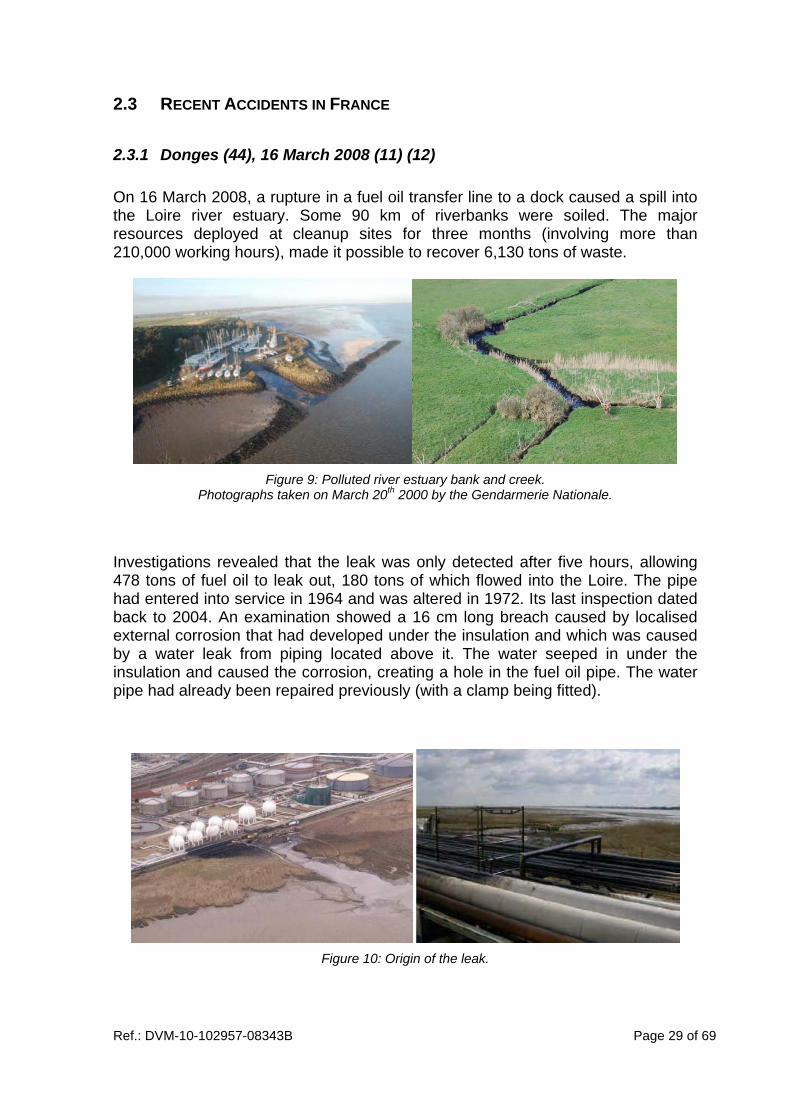
On 16 March 2008, a rupture in a fuel oil transfer line to a dock caused a spill into the Loire river estuary. Some 90 km of riverbanks were soiled. The major resources deployed at cleanup sites for three months (involving more than 210,000 working hours), made it possible to recover 6,130 tons of waste.
Figure 9: Polluted river estuary bank and creek.
Photographs taken on March 20th 2000 by the Gendarmerie Nationale.
Investigations revealed that the leak was only detected after five hours, allowing 478 tons of fuel oil to leak out, 180 tons of which flowed into the Loire. The pipe had entered into service in 1964 and was altered in 1972. Its last inspection dated back to 2004. An examination showed a 16 cm long breach caused by localised external corrosion that had developed under the insulation and which was caused by a water leak from piping located above it. The water seeped in under the insulation and caused the corrosion, creating a hole in the fuel oil pipe. The water pipe had already been repaired previously (with a clamp being fitted).
Figure 10: Origin of the leak.

Ref.: DVM-10-102957-08343B Page 30 of 69
Despite a number of anomalies found during the preceding months on this same rack, the operator did not review its inspection program to take into account the specific risks presented by this line given its proximity with the riverside. The damaged oil pipeline was shut down definitively and the inspections performed on the entire rack revealed a number of corrosion points on other lines that called for repairs.
The operator was instructed to implement a number of actions and additional measures, including:
extending inspections to other site piping with thickness measurements made around sensitive points (pipe hangers and supports, branches, etc.),
moving the water service line route to prevent it from ever being routed over an insulated pipe,
full time surveillance with a leak detection system and an alarm triggered in the control room for the pipes located close to the river,
modifying the land under the rack in order to drain any spills towards a suitable collection network,
installing a mechanism that measures the product quantities leaving a tank and those received at the end of the corresponding transfer pipe.
2.3.2 Notre-Dame de Gravenchon (76), 2008 (13) (14)
At around 13:25, an operator noticed a strong smell of gas and observed mist inside the steam cracker without being able to accurately locate the leak’s origin. At the same time, a number of combustible gas detectors were triggered.
The internal emergency services were deployed and, at around 14:45, a vertical gas jet was found from a pipe rack, around 8 meters off the ground. At 15:35, the breach was located on a 500 metre long uninsulated carbon steel 4” pipe containing liquefied butane at a pressure of 18 to 20 bars.
The line was depressurised to the flare network then cut off as close as possible to the breach at around 15:50. Overall, the leak lasted almost two and a half hours and some four metric tons of butane were released. The speed and efficiency of resource deployment prevented ignition.
The pipe contained liquefied gas isolated between two closed valves. When it expanded, it triggered a rise in pressure that was sufficient to cause the pipe to burst, even if it did not cause the heat expansion valve set at 48 bars relative pressure to open.
As shown in the photograph below, the longitudinal shaped breach was approx. 50 mm long and 20 mm wide (an equivalent diameter of approx. 30 mm). It occurred on the upper piping surface.

Ref.: DVM-10-102957-08343B Page 31 of 69
Figure 11: Breach in the 4” piping.
Dimensions: 50 x 20 mm [Source (14)]
After the incident, examination of the piping showed localised external corrosion that led to a severe loss of thickness around the hole, over the entire pipe cross section. This corrosion was caused by dripping from the melting ice that surrounded the outside of a refrigerated ethylene line located above the faulty piping.
The piping had been in service for almost 40 years. A visual inspection from below the piping had been performed in July 2006 and had not showed up any corrosion areas. As part of pressure equipment regulations, a periodic inspection was scheduled for 2009. Given the kind of product carried (non-corrosive), this should have established the condition of the pipe in the rack and determined what additional inspections or repairs would be necessary.
Following this event, the refinery put together an action plan built around an extensive pipe inspection program while the steam cracker was shutdown. A project type organisation will be put into place. Twenty five people from the inspection department and one hundred and ten to one hundred and twenty people at the maintenance level will be called on. Climbers will be contracted to inspect the racks.
A dozen flaws were identified:
low thicknesses detected on line support brackets in the racks,
some corrosion detected on insulated wet lines (operating close to 0°C),
insufficient thickness found on one branch.

Ref.: DVM-10-102957-08343B Page 32 of 69
2.4 LESSONS LEARNT
The events presented above, especially those that occurred outside of France, highlight a certain number of malfunctions that aggravated pipe degradation and that meant that this degradation was not detected early enough to be able to take suitable measures.
Without performing any statistical analysis, it is clear that pipe degradation can be aggravated by:
Failure to follow engineering best practices (standards, construction requirements, etc.): e.g. the failure to use a forged tee-piece at Grangemouth, failure to comply with separation distances between the injection point and the first elbow at Humber,
Insufficient control of operational management: e.g. use of the degraded desalter and compensating for a reduced flow rate by leaving a by-pass valve open at Martinez, or the unscheduled and frequent shutdowns of the reaction section at Grangemouth FCCU,
A lack of change management: e.g. changes in equipment operating parameters, changes to the physical properties of feedstocks, process modifications at Martinez, removal of a pump at Grangemouth, adopting a new injection point and a change of operating mode for this injection point at Humber.
In some cases, these failures are due to gaps in the risk analysis and/or the failure to take feedback into account. Both of these two aspects also contributed during the reported events to failure to inspect areas that could have been reached by advanced degradation.
Globally, it appears that the risk management systems implemented by the various operators were not effective enough to prevent degradation and to ensure the mechanical integrity of the pipes.

Ref.: DVM-10-102957-08343B Page 33 of 69
3. APPLIED MONITORING POLICIES
3.1 REGULATIONS AND GUIDELINES
Chapter 7 of the General Report4 produced by INERIS presents the regulatory context for pressure equipment in France and abroad. Additional information is provided in Annexes E, G, H and I of this same report, dedicated to the regulations applicable in France, the United Kingdom, the United States and Germany respectively.
3.1.1 Pressure Equipment (PE) Regulations in France
Pressure equipment in service monitoring is regulated in France by the Decree dated December 13th 1999 (the transposition of the Pressure Equipment Directive comprising an in-service monitoring section) and the Act dated March 15th 2000. The latter has a more limited scope, but is more prescriptive than the decree which only defines monitoring targets.
Piping, under some conditions (type of fluid, pressure, nominal pipe size (NPS, called DN in the Act)), also comes into the scope of the Act of 03/15/2000.
3.1.1.1 Piping Submission Thresholds
As a reminder, piping subject to the amended Act of March 15th 2000 includes:
▪ “Piping intended to contain a Group 1 gas with a nominal diameter larger than DN 100 or with a PS.DN result of over 1,000 bars, except for pipes with a nominal dimension less than or equal to DN 25,
▪ Piping intended to contain a Group 2 gas, including steam and superheated water, with a nominal dimension larger than DN 100 and with a PS.DN result of over 3,500 bars.”
Group 1 gases include the most hazardous substances (toxic, flammable, explosive, oxidizer, etc.). The others are included in Group 2.
Under the terms of the Act, a gas is defined as “a gas, a liquefied gas, a dissolved gas under pressure, a vapour, including water vapour and superheated water, as well as any liquid with a saturation vapour pressure which at the maximum admissible temperature exceeds the normal atmospheric pressure by more than 0.5 bars.”
4 International benchmark on regulations and practices for managing ageing in industrial
installations. INERIS DRA-09-102957-07985C. 31 December 2009.

Ref.: DVM-10-102957-08343B Page 34 of 69
In addition, a declaration, entry-intoservice inspections and periodic requalification are required for “piping with a Maximum Allowable Working Pressure (MAWP, called PS in the Act) of over 4 bars and that belongs to one of the following categories:
▪ Group 1 gas piping with a nominal dimension greater than DN 350 or where the PS.DN result exceeds 3,500 bars, except for those with a nominal dimension of up to DN 100,
▪ Group 2 gas piping with a nominal dimension greater than DN 250, except for those with a PS.DN result of up to 5,000 bars”
Application deadlines were set at:
April 22nd 2006, for constituting the description files and establishing the inspection schedule (type and periodicity),
April 22nd 2007, for performing the inspections.
3.1.1.2 Recognised Inspection Department (RID)
The requirements of the amended Act of March 15th 2000 related to the type and frequency of periodic inspections and requalifications may be modulated when the site has a RID.
In this case, the RID must set out inspection plans established according to professional guidelines approved by the Minister in Charge of Industry and be available to the agents in charge of monitoring pressure equipment.
3.1.2 Guidelines
The UIC/UFIP DT 84 guideline (15), approved by BSEI decision No. 06-194 dated 06/26/06, is used to establish inspection plans that must include:
▪ Equipment characteristics,
▪ Degradation mechanisms liable to affect each kind of equipment,
▪ Failure categories or probabilities and consequences,
▪ The criticality of every item of equipment,
▪ Monitoring actions to be performed on equipment in operation or during shutdown, especially
- the type and frequency of inspections and requalifications,
- the type, location and extent of any non-destructive testing and its frequencies,
▪ Criteria and thresholds assigned to checks and tests,
▪ Any critical operating condition limits (COCL) that may apply to equipment and the related thresholds.

Ref.: DVM-10-102957-08343B Page 35 of 69
Furthermore,
▪ The specific conditions for preparing equipment for controls or for restart,
▪ the conditions for monitoring instruments assigned to any COCL requirements,
▪ the way COCL overruns are handled,
must be recorded in the inspection plan or be covered by specific procedures or operating modes.
Prior to the application of this guideline, refinery inspection services, some as early as the mid-90s, applied a criticality-based approach. This approach has evolved over time.
Currently, pipe criticality assessment methods (as for equipment criticality) are based on the RBI standards developed by the American Petroleum Institute (API 580 (15) and API 581 (16)), while meeting the requirements of DT84.
The AFIAP (17) guideline approved by DM T/P No. 32 969 is used to classify modifications or repairs to piping subject to these regulations.
Other specific piping guidelines are also used to define practices in terms of inspection, repairs and alterations such as API 570 (10) and API 574 (18).
Some petroleum groups also have in-house guidelines for inspecting piping. Furthermore, UFIP and UIC are considering working together to produce a guideline of best practices regarding the inspection of plant piping for the entire profession (scheduled for release during the second half of 2010).
3.1.3 Field Application
For refineries, the application of the provisions of the amended Act of March 15th 2000 resulted in a major amount of piping identification and monitoring work given the significant increase in the amount of piping covered compared with previous regulations. Overall, the deadlines were met.
In addition to the piping covered by the amended Act of March 15th 2000, refiners have come to identify other piping judged to be critical and for which they have also developed inspection plans. The choice criteria applied vary depending on the facility and its environment. These voluntarily monitored pipes (ESSV) are not all covered by inspection plans as this work has not yet been completed.
For piping located off-site (outside of the battery limits), it appears from the interviews conducted that this work was made considerably more complex by the absence of any isometric drawings. Some refineries continue to use a large number of personnel for drawings and identification (Article 6, par. 4 in the amended Act of March 15th 2000) which have been extended to cover piping monitored on a voluntary basis.

Ref.: DVM-10-102957-08343B Page 36 of 69
The number of off-site pipes subject to periodic requalification varies from one refinery to another, essentially due to the classification of all or part of the petrol products (some light gasoline meets the saturating vapour pressure level of more than 0.5 bars). A large part of LPG piping is not subject to periodic requalification, as its DN does not exceed 350 and the PS.DN result does not exceed 3,500. Nevertheless, these pipes are generally covered by an inspection plan, often drawn up prior to March 15th 2000.
RIDs French mainland refineries all meet the criteria set out in Instruction DM-T/P No. 32510 and have a RID 6/12 group that applies UIC/UFIP guideline DT84 (19).
Inspectors within refinery inspection departments are in charge of organisational tasks as well as of drawing up and monitoring inspection plans. The inspection operations themselves are mainly outsourced to companies who have staff with the necessary certification for performing non-destructive testing (COFREND). These outside contractors are audited by the RID to ensure that staff certification is valid, that internal rules and instructions mentioned by the inspection plan are followed, that HSE rules are applied during work, etc.
3.2 ELABORATING AND IMPLEMENTING INSPECTION PLANS
3.2.1 Piping Condition Description
The description of piping and accessories is generally less detailed than the description of pressure vessels, which have their own files that include construction and acceptance characteristics.
Knowledge of piping characteristics is essentially based on the construction standards used. These standards are often specific to a group and they evolve over time, so it is sometimes hard to gain a precise description for piping that is decades old.
Within units, description is made easier by the existence of isometric drawings, unlike for off-site piping.
3.2.2 Degradation Mechanisms
Many complex degradation mechanisms can affect refinery equipment and piping. Knowledge of these mechanisms requires a high level of expertise in skill areas such as metals, thermodynamics, structural resistance, chemicals, etc. This knowledge is supplemented by feedback. Every mechanism depends on many factors such as the type of fluids, process conditions (pressure, temperature, flow rate, velocity, etc.), the outside environment, metallurgical aspects, etc.

Ref.: DVM-10-102957-08343B Page 37 of 69
These degradation mechanisms are recorded and described in various guidelines:
API 571 (20) which provides information on occurrence conditions, potential damage, management measures and inspection methods applicable for around sixty degradation mechanisms,
API 580 which in Annex A summarises the various mechanisms by providing a brief description, their behaviour, factors of influence and examples,
API 581 which describes the various degradation mechanisms and sets out corrosion rates according to the various process parameters and equipment metallurgy for those that lead to thickness loss,
Publications by the European Federation of Corrosion (EFC),
DT32 and DT84 that summarise in their Annex the main mechanisms encountered, examples and related effects.
These guidelines are used by corrosion engineers working for oil refiners, assigned to the central level or to the facility level. These guidelines serve in particular to produce internal guidelines (corrosion manuals) that include group (and profession-wide) feedback or to develop software to provide assistance in identifying degradation mechanisms when establishing inspection plans.
To do so, two approaches can be used:
The corrosion engineer first defines the iso-degradation loops (same fluid, same metallurgy and same process conditions), then the degradation mechanisms that are likely to have an effect according to the corrosion manual,
The inspector performs the identification using software that will identify the various degradation mechanisms liable to emerge from the piping and process description data. The corrosion engineers are involved upstream, when the software is produced, to predefine the generic degradation mechanisms assigned to the various refinery unit sections. They may also be brought in by the site to provide their expertise when required.
Once the list of degradation mechanisms has been established, the inspector evaluates the piping criticality so that the inspection plan can be adapted accordingly (type and frequency of checks, identifying specific points and proportion to be controlled, etc.).
3.2.3 Evaluating the Criticality and Defining Control Methods
Guideline DT84 sets the criteria to be taken into consideration for evaluating the probability and consequences (see General Report Annex E) but leaves each RID free to define their own scale. The combination of the failure probability and the consequences for a given item of equipment is used to determine a criticality level which is generally defined in a 5x5 matrix.

Ref.: DVM-10-102957-08343B Page 38 of 69
To undertake this evaluation, refiners use the method presented in API 581, which is adapted to suit the needs and practices of the inspection department. Consequently, the methods employed show some differences, even though they are from the same reference bases. Here are some examples.
Regarding the evaluation of consequences:
The consequences in safety terms may be defined using the simplified models presented in API 581, after defining a breach size according to the degradation mechanisms identified, in order to determine a coefficient of consequences for every degradation mechanism identified. The coefficients are then weighted to establish the overall level of consequences for the equipment. Furthermore, the consequences in safety terms may be defined with a more inclusive approach that only takes into account the equipment inventory and leads directly to a single level of consequences.
For piping, the level of consequences may be established from the upstream pressure vessel or the pressure vessels that are located upstream and downstream.
Any unavailability following the failure may be integrated or taken into account separately, in a specific scale of economic consequences that will include other parameters such as the cost of repairs or replacement and operating losses. The inspection plan will then be based on maximum consequences.
Environmental consequences can be handled independently or integrated into safety-related consequences.
Regarding the evaluation of probability:
The level may be defined for every degradation mechanism to better adapt the inspection plan accordingly or as a result of aggregating the failure probabilities of all degradation mechanisms.
These differences in the criticality evaluation method may lead to results that diverge in terms of matrix position, which is logical as DT84 leaves every RID free to determine its own assessment scales. This has been illustrated by a study performed by HSL (21), comprising an RBI analysis of a number of cases by various bodies (industrial organisations and consultants), each with its own method.
Nevertheless, it is important to point out that determining criticality is only one step in the RBI approach and that the degree of criticality of an equipment is intended to optimise the inspection means for the most critical equipments. In other words, an RBI analysis should reinforce the inspection of equipments with the highest criticality levels, as determined with the same method. Furthermore, as clearly stated in API 580, an analysis conducted as part of an RBI is never a substitute for a process-based risk analysis, but should supplement it.

Ref.: DVM-10-102957-08343B Page 39 of 69
Once the equipment’s criticality has been established, if the level does not appear acceptable, additional inspection means are determined to lower the probability (several non-destructive testing measures, increasing the proportion of specific points to be checked, increasing checking frequencies, etc.). The probability reduction criteria are defined in internal documents and are generally suited to the various degradations.
At this stage, additional management means, other than inspection, may be implemented to act on the probability or the severity. The effort will then be to reduce the degradation risk and not to improve knowledge of the degradation level (role of the inspection). The COCL concept is part of this context.
At the units, environmental consequences are generally covered by safety consequences (fire, explosion, dispersion of toxic substances) that often result in assigning a high level. Furthermore, the units are generally built on a retention area and are equipped with drainage systems to prevent any pollution. On the other hand, for off-site piping, the environmental consequences may no longer be covered by safety-related consequences (especially due to far lower pressure and temperature parameters) and the absence of any pollution prevention mechanisms does not mitigate the consequences of any release into the environment.
Currently, some RBI methods applied in refineries are not sufficiently well suited to include the environmental consequences on off-site piping. The evaluation criteria lead to a low criticality level for the vast majority of the piping. Specific criticality grids have therefore been established for certain groups so as to compensate for this insufficiency. Furthermore, the profession is set to produce a piping inspection guideline that should include this issue.
3.2.4 Key Elements in the RBI Process
A criticality-based inspection is a dynamic process that must be based on a continuous improvement approach. A criticality evaluation is based on data that is valid at the time of the analysis and on the resulting actions, which modify some of the data. The installation’s service life, and in particular the maintenance cycle, also leads to changes in the time intervals between two inspections. Consequently, the analysis must be updated periodically. Feedback (NDT results, visual inspection observations, results of periodic inspections and requalifications, incidents, etc.) must be included. This constitutes one of the drivers for continuous improvement.
For piping, the approach is relatively recent (many piping runs have only been subject to one PI or PR, as the regulation deadline for applying RPs is only two years old). The significant efforts deployed to kick off the approach will therefore only start to show tangible effects after two or three inspection cycles, on condition that the continuous improvement approach is effective.

Ref.: DVM-10-102957-08343B Page 40 of 69
The key elements in the RBI approach are therefore to have:
An efficient management system to ensure proper management of documentation, of the qualifications of the RID and outside contractor personnel who perform the checks, of the data required to conduct the analysis, of the feedback and updates to any risk evaluation.
A well documented method for determining probabilities and consequences in order to understand and, if necessary, reconsider evaluation results.
Documented procedures for defining means to reduce inspection related risks.
Documented procedures for identifying the other means of risk reduction.
The RBI process must be linked with the risk management system (SMS, especially) as many interactions exist. The RBI process may lead to increasing inspection efficiency in order to detect and quantify the degradation mechanisms that may lead to a loss of equipment mechanical integrity and in fine to a major accident. On the other hand, inspection does allow prevent or limit degradation. The risk management system comprises many elements that need to interact with the RBI approach, including the identification of major accident risks, operation management, staff training, change management and feedback management. A number of events included in the accident review chapter illustrate this. For example, the lack of interaction change management and inspection may lead to a loss of integrity with major consequences.
In the United States, following a number of accidents in the refining industry, including one in Texas City, OSHA undertook a nationwide plan5 aimed to ensure compliance with Process Safety Management (PSM) demands at 42 refineries. This system is built around 14 elements, including one that is specific to equipment mechanical integrity that applies, in addition to other equipment, to piping. The results of the OSHA program have highlighted a number of insufficiencies. Among these, the most often noticed violations are related to mechanical integrity violations (more specifically to inspections and tests) and to process safety information (most often equipment-related information with, as a priority, lacking or out-of-date P&ID data, followed by insufficient ability to demonstrate compliance with proper engineering practices for equipment).
5 Occupational Safety and Health Administration, Directive Number: CPL 03-00-004, Petroleum Refinery National Emphasis Program, June 7, 2007.

Ref.: DVM-10-102957-08343B Page 41 of 69
4. PIPING INSPECTION DIFFICULTIES
The information recorded in this part is taken primarily from the API standards, DT 32 and DT 84 guidelines and site visits.
This chapter covers both visual piping inspections, a capital aspect in detecting areas affected by external corrosion mechanisms, as well as inspections that use non-destructive testing and that are also used to detect areas affected by internal degradation mechanisms.
4.1 PRESENCE OF INSULATION
At refineries, much of the piping is insulated, both at the units themselves as well as off-site. The main reason for the presence of insulation is related to the processes, the products carried and energy efficiency. In some cases, insulation may serve to protect staff (by preventing contact burns).
Insulation is responsible for a specific corrosion mechanism called Corrosion Under Insulation or CUI that is generated by the presence of water inside the envelope (essentially due to poor sealing and condensation) and a damp environment in constant contact with the pipe. The most frequent form of CUI results in localised carbon steel corrosion. The most critical temperature range is between -4°C and 120°C. The hottest piping is far less sensitive to CUI as the water evaporates, except for piping that operates intermittently and that may alternate between dry and wet.
Among the various degradation mechanisms, CUI is the main cause of loss of containment affecting piping. The main areas affected are:
insulation penetration areas that are likely to deteriorate the jacketing sealing (tracer, heat expansion valves, T junction, etc.),
damage to the insulation jacketing (impact, movement, stamping, etc.),
vertical line ends,
poorly positioned or damaged insulation jacketing seams,
low points that may accumulate water,
areas exposed to steam releases,
areas where insulation jacketing is removed for work and then poorly replaced,
areas subject to vibration,
piping supports,
purge and drain outlets,
dirty areas.

Ref.: DVM-10-102957-08343B Page 42 of 69
Visual inspection of the insulation is essential and remains the best way to detect areas potentially affected by CUI. Inspecting these areas requires, in most cases, the insulation to be removed from the piping to make it accessible. Only radiography inspections allow NDT without removing insulation, but their use remains limited to small diameter piping in restricted areas (e.g. to evaluate the condition of a branch).
According to guideline DT84, removal of the insulation from piping subject to the amended Act of March 15th 2000 is not mandatory during periodic inspections, except when degradation is observed or when there are reasons to suspect that nonvisible parts are not in good condition. Until the third periodic requalification, only partial insulation removal is required, restricted to critical areas. Complete removal of the insulation is not necessary until the fourth periodic requalification. Annex 6 of the guideline presents a simplified diagram defining the conditions for removing equipment insulation (applicable to piping).
Refiners generally have in-house guidelines for defining CUI risk areas and the actions to be performed in terms of inspection. From the point of view of inspection, specific points presenting a heightened CUI risk are identified, then the piping criticality level, as determined during the implementation of the RBI process, determines a proportion of specific points to be stripped of insulation. For example, the criticality level may require that 25% or 50% of piping supports be checked. During the next inspection, these supports will not be checked again, so that, according to the proportion set by the criticality level, all of the supports have been checked after two, three or four inspections.
In order to compensate for inspection difficulties, an overall CUI risk management policy may be implemented. It may be based, for example, on:
The removal of unnecessary insulation or insulation that is only fitted for personnel protection (replacing it with substitute mechanisms such as protective grids in traffic areas).
A visual inspection campaign covering the condition of the insulation jacketing on all of the piping with an identification of damaged areas (where insulation will be completely removed to inspect the piping), potentially damaged areas (where insulation will be partially removed depending on the criticality of the piping) and good areas.
Sandblasting and refurbishing piping protection before fitting any new insulation.
Raising awareness among all parties involved, including those from outside contractors, so as to avoid damaging jacketing and systematically refitting insulation in accordance with best practice while ensuring it is well sealed.
Raising operator awareness to inform the inspection department of any damage or phenomena in the insulated piping environment that may cause damage (water or steam leaks, condensation drips, etc.) and improving insulation maintenance.

Ref.: DVM-10-102957-08343B Page 43 of 69
Such a policy requires very significant resources over long periods, especially to conduct the visual inspection of the insulation covering all of the piping, over its entire length, even in difficult access areas where special resources are required (nacelles, scaffolding, climbers, etc.). At refinery level, several hundred kilometres of piping or more may need inspected.
It is also important for this policy to be an overall policy and to be broken down into a set of coherent measures that include eliminating the risk where possible, evaluating any risks where they cannot be prevented, reducing risks at the source and detecting any degradation to the insulation and piping. A systematic inspection program may well see its effectiveness considerably reduced if actions to raise awareness among staff working on the installations are not undertaken. This is because inspection alone cannot prevent damage to insulation with a loss of sealing caused by any work undertaken after the inspection, and which could cause CUI which could in time lead to a loss of containment.
4.2 PIPING ENVIRONMENT ISSUES
4.2.1 Main Configurations Causing Hindrance
The environment around the piping may cause hindrance to inspections, especially due to:
Their high positioning (on racks, headline returns, etc.), that require specific means of access for inspectors and staff tasked with NDT,
The immediate space taken up by the piping (especially in racks or pipeways, running under decking, etc.), that does not allow a full visual overview of the piping or provide enough space for the testing equipment,
The type of piping supports used (especially non-welded types in pipeways or racks), that require lifting lines using (Vetter type) inflatable cushions to undertake an inspection of the contact point and then, where necessary, fit a slider pad,
Passages under roads or through bund walls that prevent most checks.
The solutions that can be provided to limit any interference due to the piping environment may turn out to be costly to implement and lead to time constraints. Nevertheless, environment-related difficulties must not result in uninspected areas. Consequently, they must not impact the choice of specific points to be checked when developing the piping inspection plan. For example, if the criticality derived from the RBI process results in 20% of supporting points being controlled, the choice of these points must not be influenced by access difficulties and the inspection plan must provide the ad hoc means required to perform the checks (nacelles, lifting platform, scaffolding, etc.).
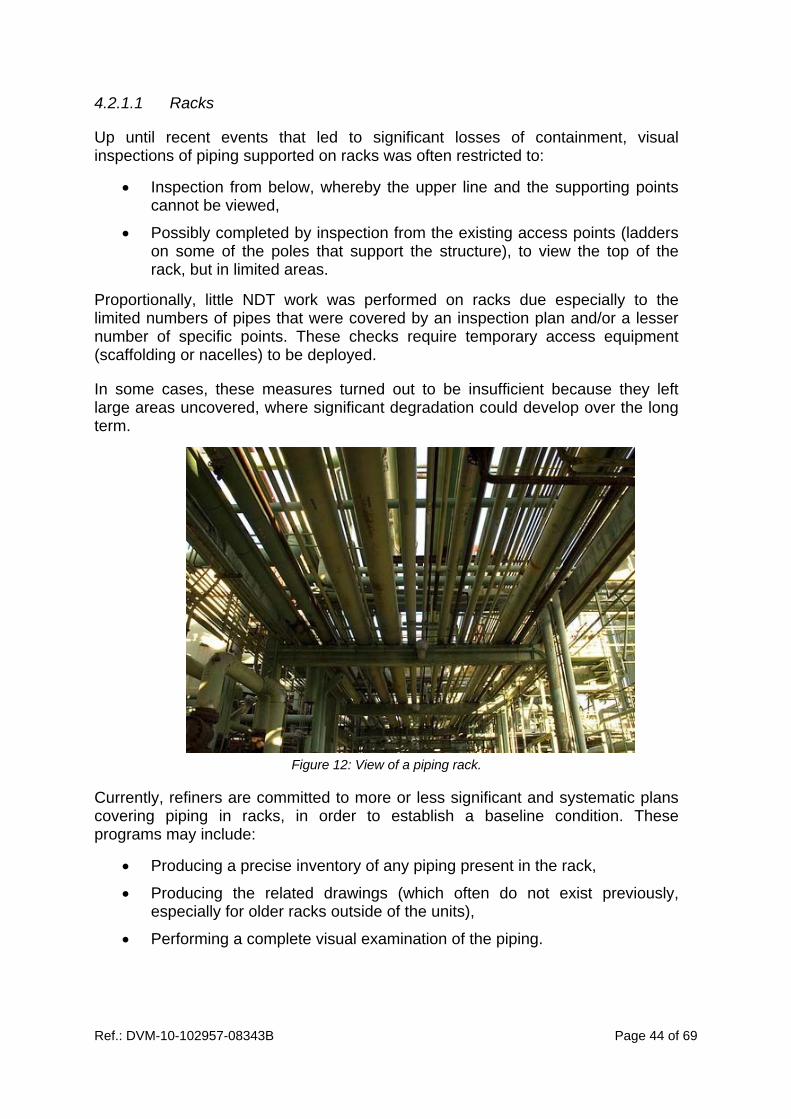
Ref.: DVM-10-102957-08343B Page 44 of 69
4.2.1.1 Racks
Up until recent events that led to significant losses of containment, visual inspections of piping supported on racks was often restricted to:
Inspection from below, whereby the upper line and the supporting points cannot be viewed,
Possibly completed by inspection from the existing access points (ladders on some of the poles that support the structure), to view the top of the rack, but in limited areas.
Proportionally, little NDT work was performed on racks due especially to the limited numbers of pipes that were covered by an inspection plan and/or a lesser number of specific points. These checks require temporary access equipment (scaffolding or nacelles) to be deployed.
In some cases, these measures turned out to be insufficient because they left large areas uncovered, where significant degradation could develop over the long term.
Figure 12: View of a piping rack.
Currently, refiners are committed to more or less significant and systematic plans covering piping in racks, in order to establish a baseline condition. These programs may include:
Producing a precise inventory of any piping present in the rack,
Producing the related drawings (which often do not exist previously, especially for older racks outside of the units),
Performing a complete visual examination of the piping.

Ref.: DVM-10-102957-08343B Page 45 of 69
From this baseline situation, the corresponding inspection plans will be updated and deployed taking into consideration the information gathered from the visual inspections performed.
As the installation of nacelles or scaffolding along the entire rack length is generally not possible, these visual inspections may have required the use of specialists able to work at heights (climbers providing protection for inspectors). These new practices must of course be implemented according to applicable workplace safety legislation, especially French Decree No. 2004-924 dated September 1st 2004, relative to the use of working equipment made available for temporary work at heights.
Figure 13: A lifeline installation for safe access when inspecting piping located on the racks
[source: Flexible Lifeline Systems (FLS)].
4.2.1.2 Off-site Pipeways
Major programs are also implemented by some refiners for off-site piping placed in pipeways, in order to establish a baseline condition. These programs may include some or all of the following actions:
Inventory of piping,
Producing the related drawings,
Scrapping unused piping,
Clearing pipeways (clearing sand from gutters, removing weeds, clutter, etc.),
Building walls to stop new build-ups and any accumulation of materials by soil runoff,
Stripping insulation off 100% of all off-site refinery piping or in areas deemed critical for the environment,
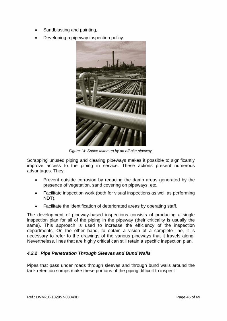
Ref.: DVM-10-102957-08343B Page 46 of 69
Sandblasting and painting,
Developing a pipeway inspection policy.
Figure 14: Space taken up by an off-site pipeway.
Scrapping unused piping and clearing pipeways makes it possible to significantly improve access to the piping in service. These actions present numerous advantages. They:
Prevent outside corrosion by reducing the damp areas generated by the presence of vegetation, sand covering on pipeways, etc,
Facilitate inspection work (both for visual inspections as well as performing NDT),
Facilitate the identification of deteriorated areas by operating staff.
The development of pipeway-based inspections consists of producing a single inspection plan for all of the piping in the pipeway (their criticality is usually the same). This approach is used to increase the efficiency of the inspection departments. On the other hand, to obtain a vision of a complete line, it is necessary to refer to the drawings of the various pipeways that it travels along. Nevertheless, lines that are highly critical can still retain a specific inspection plan.
4.2.2 Pipe Penetration Through Sleeves and Bund Walls
Pipes that pass under roads through sleeves and through bund walls around the tank retention sumps make these portions of the piping difficult to inspect.

Ref.: DVM-10-102957-08343B Page 47 of 69
At these levels, no visual inspection is possible and most NDT techniques cannot be implemented. Most likely, guided wave checks would meet requirements where necessary, but opinions regarding their efficiency differ.
In order to solve these problems, pipes that pass under roads through sleeves are tending to disappear (by digging out and eliminating the crossing or by building overpasses). For piping that passes through bund walls, one of the solutions implemented by refiners is the restriction of external corrosion using different methods:
Grouping the piping, digging out the earth bund wall over a short section and building a concrete wall with a sleeve set into it and with 6 H fire break seals,
Digging out the bund wall, inspecting, refurbishing and fitting a bitumous coating or running the pipes through sleeves before rebuilding the bund wall.
4.3 OPERATING CONDITION ISSUES
The presence of ice on piping used at low temperatures (steam crackers) prevents visual inspection or non-destructive testing during operations. These operations can therefore only be performed during shutdown periods when the refrigerating products are removed to check the condition of the piping.
Due to condensation phenomena, the so-called “damp” piping that operates at between -4°C and 10°C is sensitive to external corrosion but presents fewer difficulties in terms of inspection. The coldest lines are those least subject to this form of degradation (except those that operate cyclically) but they may generate corrosion in their close environment. This is especially the case in racks, where the cold may propagate by conduction via supports and therefore create condensation areas on the supports themselves, on the rack structure or on neighbouring piping.
A recent event has also shown that water running off cold piping promotes external corrosion affecting piping located below it, resulting in containment failure.
4.4 EXPANSION COMPENSATORS
Expansion compensators form specific points along the piping and are hard to inspect when in operation using conventional methods due to their layout. They can still be covered by an expansion check based on temperature variations.

Ref.: DVM-10-102957-08343B Page 48 of 69
During shutdowns, the compensators can be disassembled for an internal inspection by performing a visual check on the waves between which corrosion phenomena may occur due to condensation, especially in the case of successive shutdowns. The track record is therefore taken into account. Disassembly and especially reassembly phases may be delicate (with the need to realign two piping sections to avoid creating shearing stresses).
At the furnace exit, compensators are also subject to coking phenomena that may alter their performance.

Ref.: DVM-10-102957-08343B Page 49 of 69
5. SERVICE LIFE AND REMAINING LIFE CONCEPTS
5.1 SERVICE LIFE
For refinery piping, the concept of a maximum service life that is set at the time of manufacture or entry into service, is not used. On the other hand, professional guidelines and refiners work on the basis of remaining pipe life, updated according to the results of controls, in order to determine whether to keep them in service or replace them.
This remaining life concept does not only apply to degradation mechanisms that lead to a loss in metal thickness, generally with slow kinetics (many years before reaching a critical thickness).
Remaining life is determined on the basis of corrosion rates that may evolve over time according to the type of fluid carried, operating conditions or process-related modifications. As a result, for internal degradation mechanisms, the piping located at production units is more likely to suffer from variations in the corrosion rate over time than off-site piping. For example, a change in crude oil may have a tangible influence on corrosion rates in atmospheric distillation units and units located downstream.
Consequently, by taking into account these variations, this approach is used to, at best, determine the piping’s service life over time, according to the degradation mechanisms and their severity. This approach also means that the piping no longer needs to be considered as a whole, but can be used to identify those sections most subject to degradation, generally at the specific points that are considered to be the piping’s weak points. As a result, partial replacements or localised repairs may be implemented to ensure the integrity of all of the piping over a longer period.
The corrosion rate that will be used to determine the remaining life may be:
estimated from tables, especially those in API 581 in which the data is conservative, and/or the knowledge of corrosion experts,
calculated from thickness measurements.
For refinery piping, the general practice is to calculate a corrosion rate from thickness measurements. These are monitored over time and are recorded in the piping history, a part of the inspection plan.
For degradation mechanisms that do not lead to any loss of thickness (e.g. vibration fatigue, cyclic fatigue, stainless steel cracking under stress in the presence of chlorides, etc.), this concept is not applicable. In such cases, ageing management involves reducing or even eliminating these specific degradation mechanisms:
by anticipating them at the design level (a metallurgical choice),

Ref.: DVM-10-102957-08343B Page 50 of 69
by adjusting operating conditions (pressure, flow rate, temperature, pH, etc.),
by developing specific surveillance to avoid encountering the conditions that are likely to encourage the appearance of these specific mechanisms (thermographics applied to furnace tube lines in addition to temperature indicators to identify any hot points that may cause creep, indicating and reducing vibration phenomena on branches by fitting reinforcing mounts, etc.),
etc.
Consequently, one of the measures is to set “Critical Operating Condition Limits (COCL)”. This concept is set out in the Annex to DM-T/P No. 32510, par. 3.1 as being a “threshold set at a physical or chemical parameter (temperature, pH, fluid rate, contaminant concentration) that when exceeded may have a notable impact on the behaviour, state or damage to the equipment, or that may cause the appearance of a new degradation phenomenon”.
5.2 MEASURING PIPE THICKNESS
5.2.1 Thickness Measurement Locations
Thickness measurement point locations are a determining element. This is because the degradation mechanisms that cause a loss of thickness are often generalised mechanisms for piping, but any non-uniformity in them is responsible for the appearance of preferential areas where the degradation mechanisms will show increased rates. To properly evaluate the remaining life of piping, it is therefore necessary to first identify the measurement points (TMLs6) that are the most relevant, i.e. those used to determine the maximum degradation rates.
These preferential areas, known as specific points, are specific to each degradation mechanism. Consequently, for example, successive elbows, parts close to injection points or turbulence areas downstream from regulation valves, especially in flash areas, will all be more sensitive to erosion. Furthermore, vents, connection T joints, supports, low points on a vertical piping section, purges and drains or more generally any likely to cause a water inlet or to form a retention area, will be potential areas for corrosion under insulation. The following illustration is used to non-exhaustively view some specific points, regardless of their degradation mechanisms.
6 Thickness Measurement Locations

Ref.: DVM-10-102957-08343B Page 51 of 69
Figure 15: Examples of specific points on piping.
Many guidelines provide details on degradation mechanisms to be envisaged (DT 84, API 580, API 581) and specific points along the piping to be monitored for each of these (API 570, API 574 (18)). Generally, guidelines are produced at by the oil group to set the inspection criteria that apply at specific points. These make work easier for corrosion engineers and for the inspection departments at the facilities as well as harmonising practices within the same group.
Generally, the number of specific points to be checked depends on the criticality of the line established during the RBI process. Each group or facility defines its own policy, but generally, the higher the criticality, the greater the number of TMLs and the greater the proportion of specific points to be checked. For example, for a CUI, the thickness measurements at the supporting points may be performed systematically or only 50%, 25% or 10% of them, depending on the criticality level established.
The number of TMLs also depends on the type of specific point. For an instrumentation branch, the measurement points will be limited to the branch itself whereas for others that are likely to propagate the degradation, such as a general erosion phenomenon generated by an injection point, the TMLs will be extended to the first elbow level and to the downstream condenser inlets.
Instrumentation branch:
‐cracking due to vibration fatigue ;
‐thickness < the line
Heat expansion valve:
‐corrosion blockage
Elbow:
‐erosion
‐internal corrosion
Dead branches:
‐fatigue
‐corrosion under deposits
Expansion compensator:
‐inter‐wave corrosion
‐sensitivity to condensation
Injection points:
‐erosion / corrosion
Flange seals:
‐crushing
‐expansion
Insulation:
‐CUI
‐numerous specific sensitive points
‐requires insulation to be removed for visual inspections and most NDT
Contact point:
‐Friction
‐External corrosion
Valves / Non return valves:
‐corrosion blockage
‐clogging
‐seat and/or valve erosion
Supports:
‐external corrosion
‐heat stress
‐vibration stress
‐heat transfer to racks
Reduction:
‐erosion
‐internal corrosion

Ref.: DVM-10-102957-08343B Page 52 of 69
5.2.2 Methods Applied
The main methods used to measure thicknesses are ultrasonic techniques and, to a lesser extent, radiography examinations (see General Report chapter 6.2.2).
Generally, API 570 recommends the use of ultrasonics for piping with a diameter in excess of 1” and radiography for those with diameter of 1” or less.
In practice, it appears that some refiners use radiography on far larger diameter pipes (up to 4” regularly and in some cases up to 8”), especially to perform measurements on insulated lines. This technique offers the advantage of not requiring any removal of insulation, providing an overview of the piping section, but it does however require a geometric adjustment for the larger diameters to accurately determine their thickness. This method also has drawbacks relating to radiation protection for staff. The use of this approach on larger diameter piping necessarily requires the use of a cobalt radiation source, and is consequently banned for regular thickness measurements.
Unlike radiography, ultrasonics provide only localised thickness measurements. As corrosion is not generally uniform, it is important that the location of the measurement points consistently be as close as possible between two controls to ensure that the measurements are reproducible and to determine an accurate corrosion rate. Precise physical identification of the areas to be checked may be difficult. Besides, ultrasonics do not allow measurements to be taken without removing the insulation. If ad hoc measurements are not taken for insulated piping, then these checks may cause degradation to insulation sealing, and in the end may cause CUI. By fitting a window to the insulation envelope, the risk of water seeping in due to thickness measurements can be limited.
Ultrasonics, like all other techniques, require a good degree of operational skill to ensure their reliability, especially when it comes to calibrating measurement equipment, the roughness of the pipe surface, the way the effects of temperature are handled, etc. It should be noted that this kind of test, like other NDT techniques, is almost exclusively performed by outside contractors. Consequently, the refinery needs to implement the necessary action to ensure the skills of the staff involved and the efficiency of the organisations brought in. Often, contracts are medium term (3-5 years) and the choice of staff is validated by the refinery to guarantee a degree of stability.
5.3 DETERMINING CORROSION RATES
Corrosion rates are determined from thickness measurements taken at the same point, during a given time interval.

Ref.: DVM-10-102957-08343B Page 53 of 69
This time interval may be taken:
Between the last two thickness measurements, in this case it is called the short term corrosion rate (ST), or
Between the first and the last thickness measurement, in this case it is called the long term corrosion rate (LT).
Monitoring both of these rates is useful. The first is used to better observe slight changes in rate between the various intervals (both increases and decreases) and thereby provides a more precise vision of the corrosion rate during the last interval. On the other hand, this value is more sensitive to measurement errors. The second is used to establish a trend since the piping entered into service. The value retained is often left up to the RID inspector.
As mentioned above, the number and location of measurement points are a determining factor when estimating the maximum corrosion rate for a iso-degradation loop as degradation is never completely uniform over the entire loop. Consequently, it is necessary to determine the corrosion rates for all of the TMLs and retain the most penalising rate to calculate the remaining life and the deadline for the next thickness measurements.
5.4 REMAINING LIFE AND NEXT CHECK DEADLINES
When piping is designed, its thickness is calculated to allow for internal pressure as well as other physical constraints (weight, wind, etc.), to which an additional layer of corrosion is added. Each of the groups then applies its own construction standards that define all of the parameters that apply to the line (maximum service pressure and temperature, metallurgical aspects, diameter, thickness, valves, flanges, type of seal, nuts and bolts, etc.).
The estimated remaining in-service life is the time left before a minimum thickness is reached, at a constant corrosion rate (established from thickness measurements). As appropriate, this minimum thickness may be said to be the replacement thickness or the scrapping thickness. The following figure is used to illustrate the remaining life concept. Each point Mx represents a thickness measurement.
In order to leave a greater amount of freedom and to include an additional safety factor, some refiners define two critical thicknesses: a minimum thickness and a greater thickness known as the alert thickness. In this case, the remaining life is estimated on the basis of the alert thickness.

Ref.: DVM-10-102957-08343B Page 54 of 69
Figure 16: Estimated remaining service lives.
If the thickness measurements do not show any anomalies, the next deadline is defined from the remaining life. Different approaches may be taken. Depending on the refiner, a fixed coefficient is applied to the remaining life (e.g. 0.5 or 0.8) to define a theoretical date for the next thickness measurements. Others have established factors that evolve according to the criticality set during the RBI process, factors that may vary from 0.1 to 1 and that are defined in the matrix. Logically, the higher the criticality of the piping, the lower the factor. For example, if the remaining life is determined as 15 years, the theoretical deadline for the next thickness measurements may be 18 months if the factor is 0.1 (very high piping criticality) or 15 years if the factor is 1 (very low piping criticality).
Nevertheless, it appears that the calculated remaining life and the theoretical deadline for taking the next thickness measurements are, in a very large majority of cases, in excess of 6 or even 12 years (the maximum regulation deadlines for pressure equipment periodic inspections and requalification at facilities with an RID applying DT847). In this case, the deadline for the next thickness measurements for piping subject to such measurements is set at 12 years at most (the thickness checks may be made before the periodic requalification that is performed during the shutdown so as to anticipate any maintenance work that may be required).
With the application of the remaining service life concept, thickness measurements may not be taken systematically every time a unit is shut down.
7 BSEI decision No. 06-194 dated 26/06/06 covering the approval of a professional guideline
relating to the establishment of inspection plans
Residual service life
(ST)
M0
M1 M2
M3
Residual service life
(LT)
Thickness
Deadline
Replacement
thickness

Ref.: DVM-10-102957-08343B Page 55 of 69
5.5 MAINTAINING PIPING IN SERVICE
If any anomaly is detected, the decision on whether to maintain piping in service is based on a “Fitness For Service (FFS)” analysis that is intended to determine whether the piping can continue to be used safely until the end of the desired period (generally the next scheduled shutdown). This analysis may result in the decision to continue operating in the usual conditions (admissible faults), to adjust operating conditions to limit the degradation mechanism, to perform repairs in service (e.g. fitting a sealing box), to step up surveillance of the anomaly found (in quality and frequency terms) or to replace the piping.
API 570 describes the general principles that apply to piping and makes reference to API 579 (22) for applying FFS techniques.
In practice, if the anomaly observed means that the remaining life will not extend as far as the next shutdown, then various measures may be taken:
for a highly localised loss of thickness, piping may be repaired (for those subject to the Act of March 15th 2000, application of the AFIAP8 guideline),
surveillance may be stepped up until the next scheduled shutdown (thickness measurements at reduced intervals),
operating conditions may be adjusted to reduce the corrosion rate (flow rate, temperature, etc.),
the pressure may be lowered to reduce the minimum threshold level.
Depending on the case, these measures may be combined and if the process allows it, replacement of the incriminated section of piping may be considered before the unit is shut down.
For anomalies unrelated to thickness losses, such as, for example, the detection of cracks or operating conditions that are more severe than expected (detecting major and unusual vibratory phenomena), then finite element calculations may be made but any implementation of these remains rare for piping. In this case, the refiner calls on outside contractors who have the required expertise and tools. The decision based on the calculation results will be taken collegially between modellers, refinery departments and, generally, group experts.
8 Guideline on the classification of pipework alterations or repairs at plants subject to French
regulations, approved by DM-T/P No. 32 969 dated 28 May 2004.


Ref.: DVM-10-102957-08343B Page 57 of 69
6. CORROSION MANAGEMENT
6.1 GOALS
A considerable amount of energy is contained in the pressure equipment and it can, should the enclosure fail, cause the equipment to be destroyed spraying hazardous fragments and causing loss of containment of dangerous substances that, in a refinery, are generally flammable or even toxic.
Inspecting such equipment is therefore essential to ensure its integrity. Using suitable inspection means, this should identify any alterations affecting the equipment before they become dangerous. Nevertheless, inspection alone is not sufficient and should be combined with measures regarding:
equipment design,
equipment operating conditions,
equipment maintenance,
possible equipment repairs.
As stated in preceding chapters, there are many degradation mechanisms in refineries (around sixty have been identified by API standards). Operator knowledge of these degradation mechanisms and measures intended to prevent or reduce their kinetics therefore constitutes an essential factor in managing installation ageing.
An example of corrosion management measures applied to the atmospheric distillation unit is provided as an indication in this chapter. Naturally, corrosion management is not limited to this unit alone but applies to all of a refinery’s installations. Costs relating to these measures are provided as an indication.
6.2 COST IN REFINERY SECTOR
In 2001, a study was conducted to estimate costs related to corrosion management in the refining industry in the United States, which represents close to one quarter of the world’s capacity, with 163 operational refineries (23). The overall cost, including the cost of corrosion specific maintenance, shutdowns for inspection and repairs (essentially related to regulatory obligations), plugging and fouling due to corrosion alone, has been set at $0.65 a barrel. This cost represents a significant share of overall operating costs, around $5.51 a barrel, and can be compared with refining margins in the US that averaged less than $1 a barrel throughout the 1990s.

Ref.: DVM-10-102957-08343B Page 58 of 69
The potential for internal corrosion is especially dependent on the quality of the crude oil refined which, depending on its origin, will contain variable quantities of corrosive agents, such as:
Mineral salts,
Chlorines (essentially NaCl, MgCl2 and CaCl2),
Organic acids (especially naphthenic acids),
Sulphur compounds.
The presence of these corrosive agents implies, right from the first refining step, specific operations to reduce equipment corrosion in the atmospheric distillation unit, as well as to stop any propagation of problems towards downstream units (corrosion, cocking, catalyst poisoning, etc.).
6.3 EXAMPLE OF CORROSION MANAGEMENT ON AN ATMOSPHERIC
DISTILLATION UNIT
The main actions taken to mitigate corrosion at the atmospheric distillation unit level are briefly described below.
6.3.1 Desalting of Crude Oil
The salt contained in crude poses two main problems:
it clogs the preheating system leading to corrosion under the deposits with an ever greater loss in energy efficiency,
the production of hydrochloric acid by high temperature hydrolysis (350°C) of the magnesium chloride and to a lesser extent, calcium chloride.
To overcome these difficulties, desalting is one of the main ways of mitigating corrosion. It takes place in the preheating system in the atmospheric distillation process. To reduce preheater fouling, part of the desalting water injection takes place upstream. The operation itself is performed in the desalter so that the salts are dissolved in the water, then separated out by coalescence and settling of the aqueous phase. Desalter efficiency is dependent on a variety of parameters (water/crude oil interface, temperature, washing rate, injection point, water quality, etc.). It is sensitive to crude oil quality, i.e. the quantity of salt and especially its density. The heavier the crude to be treated is, the harder the desalting operation will be (high viscosity, low density difference between crude and water making gravity-based settling less efficient and the oil-water emulsion more stable).

Ref.: DVM-10-102957-08343B Page 59 of 69
The degree of desalting typically obtained is between 85 and 95%. To avoid any hydrolysis between the magnesium chloride and the remaining sodium, and thereby reduce corrosion problems in the column head circuit, a soda solution is injected downline from the desalter. Nevertheless, the aim that is typically sought is to optimise the desalting operation to limit soda consumption and ensure that the product still to be treated is less sodium laden so as to reduce coking in the VD or viscoreduction furnaces. Furthermore, sodium injection may in turn cause steel fragilisation phenomena.
All of the hydrochloric acid is generally not neutralised by the soda. The small percentage remaining requires an ammonia injection at the column head together with a corrosion inhibiter that combines a filming base and a neutralising base to complete the ammonia’s action.
During these neutralisation operations, the pH level should not become basic or it will form iron sulfide.
The efficiency of corrosion prevention measures can be monitored by checking the condensed water at the head tank level (for pH level, Fe2+ and Cl- content).
6.3.2 Protection Against Corrosion by High Temperature Sulphur
The total sulphur content of crude oil generally varies between 0.05 and 5% (24). It is present in most of the heavy cuts in the form of sulphur components of naphthenic hydrocarbons and aromatics. Crude oil generally also contains a small amount of dissolved hydrogen sulphide. However, this gas is formed during the various refining operations or by a thermal breakdown of sulphide laden hydrocarbons during distillation.
Carbon steels are sensitive to corrosion caused by high temperature sulphur that generates iron sulphide responsible for plugging. Furthermore, these components that have pyrophoric properties present a significant hazard during shutdowns.
So as to prevent this degradation mechanism, steel alloys, primarily chrome alloys are preferred, especially in the furnace tube. The atmospheric distillation head circuit, where corrosion is accentuated by gas speed, may also benefit from the use of chrome steel alloys (12% or even 18% content).
6.3.3 Protection Against Corrosion by Naphthenic Acid
Crude oil contains carboxylic acids (R-COOH) in variable proportions. Among these, naphthenic acids, a group of cyclic radical acids generally derived from cyclopentane and cyclohexane, are known for their very markedly corrosive nature in the 200 – 400°C (NAC) temperature range. Beyond this range, the phenomenon disappears due to the dissociation of the acids.
Crude oil acidity is determined by neutralisation using caustic potassium. The TAN index measures are expressed in mg KOH/g of crude but are not specific to naphthenic acids. They do however provide a relevant indication for corrosion experts.
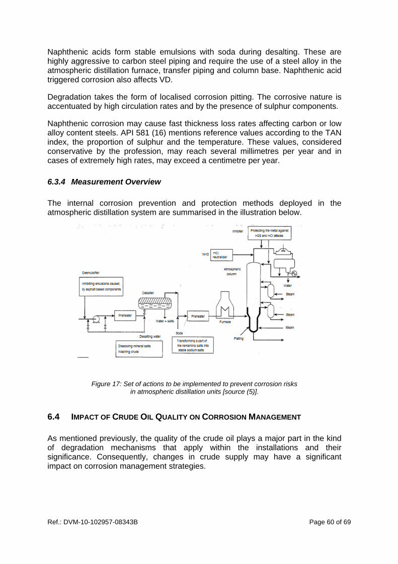
Ref.: DVM-10-102957-08343B Page 60 of 69
Naphthenic acids form stable emulsions with soda during desalting. These are highly aggressive to carbon steel piping and require the use of a steel alloy in the atmospheric distillation furnace, transfer piping and column base. Naphthenic acid triggered corrosion also affects VD.
Degradation takes the form of localised corrosion pitting. The corrosive nature is accentuated by high circulation rates and by the presence of sulphur components.
Naphthenic corrosion may cause fast thickness loss rates affecting carbon or low alloy content steels. API 581 (16) mentions reference values according to the TAN index, the proportion of sulphur and the temperature. These values, considered conservative by the profession, may reach several millimetres per year and in cases of extremely high rates, may exceed a centimetre per year.
6.3.4 Measurement Overview
The internal corrosion prevention and protection methods deployed in the atmospheric distillation system are summarised in the illustration below.
Figure 17: Set of actions to be implemented to prevent corrosion risks
in atmospheric distillation units [source (5)].
6.4 IMPACT OF CRUDE OIL QUALITY ON CORROSION MANAGEMENT
As mentioned previously, the quality of the crude oil plays a major part in the kind of degradation mechanisms that apply within the installations and their significance. Consequently, changes in crude supply may have a significant impact on corrosion management strategies.

Ref.: DVM-10-102957-08343B Page 61 of 69
Currently, the general trend is towards refining heavier and more acid crudes. One of the reasons for this is a financial argument, as these crudes reduce supply costs for the refinery, and therefore potentially increase profit margins. Nevertheless, they impose additional costs in terms of optimising corrosion prevention and protection means.
In addition to adjusting the desalter settings, which are limited by design, technological evolutions that require the equipment to be changed or modified may be retained (a multiplication of the coalescence stages, alternative electric field layouts, etc.). In certain cases, these technological changes may also reduce maintenance downtimes that are generally long and time-consuming for desalters using old technology (requiring periodic sediment deposit cleanouts, etc.).
Furthermore, additional costs are often associated with the use of upgraded steels, to the cladding of all or a part of the equipment (e.g. the column head), greater recourse to chemical treatments (corrosion inhibitors, neutralisers) and increased monitoring (analyses and non-destructive tests).
Again according to the study conducted on refineries in the United States (23), the additional cost of NDT and corrosion samples for an atmospheric distillation unit ($0.01 a barrel) is far less than the additional cost of intensifying chemical treatments that comes to $0.10 a barrel. Refining has for that matter become the leading consumer of corrosion inhibiters in the United States, at a cost that was constantly on the rise between 1981 and 1998, growing from $130 million to $246 million.
The other alternative is to upgrade the quality of the steel used in those areas likely to be strongly impacted by any increase in the acidity of the crude that is processed, which leads to increased costs that exceed those of any intensification in the chemical treatment. It still remains comparable over long write down periods. For an atmospheric distillation plant that processes 120,000 barrels per day, the investment represents between $12 and $20 million, i.e. over a 20-year period, an additional cost of $0.18 to $0.30 a barrel. This choice is therefore based on a long term policy approach.
Other corrosion management strategies include using blending before the product enters the unit, especially to reduce the density and the viscosity of the atmospheric distillation unit’s loading (for better desalting) or to reduce the naphthenic acid content.
These measures, as much as any equipment and piping inspections, contribute to managing ageing. Some are involve the implementation and monitoring of COCL approaches.
Internal corrosion management is not limited to atmospheric distillation units alone. Documents such as API 580 (15) and 581 (16) that describe degradation mechanisms, units impacted or corrosion rates according to the steel quality constitute a valuable source of help when establishing management strategies.


Ref.: DVM-10-102957-08343B Page 63 of 69
7. CONCLUSION
Recent incidents and accidents in France, especially at refineries, have led the French Ministry of Ecology, Energy, Sustainable Development and the Sea to start an industrial installation ageing management plan. Among the many stakeholders involved, INERIS has been involved by producing an international benchmark on regulations and practices. This report is specific to refinery piping. Readers are invited to refer to other reports9 written by INERIS, should they require further details on the general principles related to the monitoring of equipment, pressure equipment regulations in force in France and abroad or for specific measures that apply to other types of equipment (storage tanks, electrical equipment, etc.).
An analysis of the causes of some significant events that occurred at refineries has highlighted a two-fold failure:
Failure of degradation prevention measures,
Failure of degradation identification, control and measurement processes (activities that come under inspection).
Ageing pipe management must therefore apply to both these aspects. For piping that has been in service for decades, which represents a major share of the piping at French refineries, degradations, modifications and repairs have accumulated. Consequently, a greater inspection effort appears necessary as compared with recent piping. Nevertheless, implementing preventive measures must take priority and the management system through its various elements (training and qualification, operational management, change management, etc.) must efficiently contribute to it. A vast plan for evaluating PSM at US refineries, initiated following a number of serious accidents, has shown that the management systems implemented by the operators presented numerous non-conformities and were not therefore efficient enough.
Regarding monitoring, the French Act of March 15th 2000 significantly increased the amount of piping covered. It therefore contributes to reinforcing inspections. Currently, the newly regulated piping is generally subject to a single control. The real impact in terms of reducing losses of containment is as yet still hard to measure. Nevertheless, the fact that this requirement has come into force has given rise to a major workload, especially in terms of establishing descriptions, making records and sketching isometric drawings, especially for off-site piping where these were seldom available. These efforts should normally result in an improvement in matters.
9 International benchmark on regulations and practices for managing industrial installation ageing.
INERIS DRA-09-102957-07985C. 31 December 2009.
Managing industrial installation ageing; Refinery storage benchmark; DRA-102957-08289B. February 2010.
Ref.: DVM-10-102957-08343B Page 64 of 69
The history of facility piping is generally less well known than that of vessels. Yet this is an important element when it comes to managing ageing as time is not the only parameter to be taken into consideration. Operating conditions and the maintenance operations performed on the piping, as well as changes to it, are fundamental elements that influence the various degradation mechanisms faced, both in number and in intensity. For example, an increase in furnace temperatures may cause the appearance of a creep phenomenon, increased velocity may cause erosion, etc. Taking account of piping history therefore contributes to the relevance of the inspection plan when it is put together.
In the field, the presence of RIDs at refineries is an obvious advantage when it comes to monitoring equipment: developing an RBI methodology, full time presence on-site, interactions with other departments (operations, maintenance, safety, etc.), managing expertise (equipment history, knowledge of degradation mechanisms, feedback, etc.), establishing and monitoring inspection plans, monitoring outside companies that perform NDT work, using the results, etc.
All the refineries visited have committed to a risk-based inspection approach to the production of their inspection plans (for vessels and piping), and with a methodology developed on the basis of common standards (API standards 580 and 581, UIC/UFIP DT84 guideline), but adapted to each group. Generally, the environmental consequences appear to have been insufficiently taken into consideration, more especially for off-site piping where these kinds of consequences may turn out to be preponderant when it comes to safety-related consequences. Initiatives have already been taken by some refineries to introduce this particular aspect into their RBI methodology.
The quantity and extent of piping at refineries (both within the units and off-sites), require inspection efforts to be focused on the most critical pipes and more precisely on specific points on these pipes which may be more exposed to degradation mechanisms. Some of these specific points can be found in difficult access areas (racks, pipeways, mounting up high, passage across roads, passage through bund walls, etc.) but the choice of specific check points should not be influenced by these difficulties.
Recent events and the extension of monitoring to more piping that has been in service for decades have led some refiners, sometimes with the support of the authorities, to kick off ambitious systematic checking plans, even in difficult acces areas, so as to produce a baseline condition of their facilities. These plans may, for example, include performing a 100% visual inspection, whereby insulation is removed from major portions of the lines, implementing corrective or preventive actions to mitigate degradation (sandblasting, painting, uncluttering, eliminating sections passing through sleeves, etc.).

Ref.: DVM-10-102957-08343B Page 65 of 69
These plans, which are not widespread, should therefore allow refineries to:
Gain a better overall and more precise vision of the condition of pipes, especially for those which have been in use for many decades and were not regularly monitored but could nevertheless have significant environmental consequences (primarily off-site),
Refurbish (repair, protect, replace, etc.) piping or piping sections that need it,
Reduce or eliminate some degradation mechanisms.
Once these plans have been completed, an acceptable level of pipe ageing management should be achieved, through the following combined efforts:
Cost-effective optimisation of degradation mechanism prevention measures, with the implementation of a risk management system (better operation management, change management, feedback management, contractor management...),
A more efficient RBI approach to support inspection programme design, implementation and revision.


Ref.: DVM-10-102957-08343B Page 67 of 69
8. BIBLIOGRAPHY
[1] BARPI. Accidentologie relative aux canalisations - Ruptures de canalisation sur sites industriels.
[2] BARPI. Explosion dans une unite de craquage sur un site de raffinage. Séminaire retour d'expérience - IMPEL. June 2001.
[3] BARPI. Résumé ARIA n°14951. Raffinage de pétrole. Etats-Unis, Martinez.
4] CSB. Investigation report, Refinery Fire Incident. March 2001, n°99-014-1-CA.
[5] WAUQUIER, Jean-Pierre. Le raffinage du pétrole. Procédés de séparation. s.l.: Published by IFP. Editions Technip, 1998.
[6] American Petroleum Institute. API 750: Management of Process Hazards. 1990.
[7] HSE & SEPA. Major incident investigation report: BP Grangemouth, Scotland, 29th May - 10th June 2000. 18th August 2003.
[8] HSE. Public report of fire and explosion at the CONOCOPHILLIPS Humber Refinery on 16 April 2001.
[9] BARPI. Résumé ARIA n°20541. Raffinage de pétrole. Royaume-Uni, Immingham.
[10] American Petroleum Institute. API 570: Inspection, Repair, Alteration, and Rerating of In-service Piping Systems. Second edition, October 1998.
[11] BARPI. Résumé ARIA n°34351. Raffinage de pétrole, Donges.
[12] TOTAL. Fuite d'hydrocarbures en Loire, Refinery de Donges, 16 March 2008.
[13] BARPI. Résumé ARIA n°35146. France, Notre-Dame-de-Gravenchon.
[14] ExxonMobil. Incident line de butane NDG, 6 septembre 2008.
[15] UIC/UFIP. DT84 - Guide pour l’établissement d’un plan d’inspection permettant de définir la nature et les périodicités d'inspections périodiques et de requalifications périodiques pouvant être supérieures à cinq et dix ans. June 2006, révision 1.
[16] American Petroleum Institute. API580, Risk-based Inspection. First edition, May 2002 .

Ref.: DVM-10-102957-08343B Page 68 of 69
[17] American Petroleum Institute. API 581, Risk-based Inspection Technology, Downstream Segment. Second edition, September 2008.
[18] AFIAP. Guide de classification des modifications ou réparations de tuyauteries d'usine soumises à la réglementation Française. February 2004.
[19] American Petroleum Institute. API 574 Inspection practices for piping system components. Second edition - 01-Jun-1998.
[20] American Petroleum Institute. API RP 571 - Damage Mechanisms Affecting Fixed Equipment in the Refining Industry. 1st Edition, December 2003.
[21] HSL. Risk Based Inspection, a case study evaluation of onshore process plant. 2002.
[22] American Petroleum Institute. API 579 - Fitness For Service. Second Edition, June 2007.
[23] CC Technologies Laboratories, Inc. to FHWA. Corrosion costs and preventive strategies in the United States. FHWA-RD-01-156, September 2001.
[24] WAUQUIER, J.P. Pétrole brut. Produits pétroliers. Schémas de fabrication. s.l.: Published by IFP. Editions Technip, 1998.
1

Ref.: DVM-10-102957-08343B Page 69 of 69
9. LIST OF ANNEXES
Mark Precise description Nbr of pages
A Summary of refinery visits 15


Réf.: DVM-10-102957-08343B Annexe A
Annex A
Summary of refinery visits


Ref.: DVM-10-102957-08343B Annex A Page 1 of 15
1. CONTEXT As part of its work on managing ageing in the prevention of technological hazards as requested by the French Ministry of Ecology, Energy, Sustainable Development and the Sea, INERIS visited six refineries in France between May and June 2009. The purpose of these visits was to record practices observed in the field as applied to the inspection and maintenance of piping and storage tanks, to the management of feedback and the management of the skills and qualifications of staff involved. The safety measures and civil engineering works relating to the piping and storage tanks also fell within the scope of this study. For each of the six refineries, a day of discussions took place between two INERIS engineers and facility representatives (inspection department, corrosion expert, maintenance expert, HSE, etc.) and in some cases with the head office of the oil company operating the refinery. The elements collected during these visits have in part been included in the various reports published1. A summary is also presented hereinafter. INERIS wishes to thank all of the persons involved during these visits, and who by sharing their experience contributed to this evaluation.
2. SUMMARY OF VISITS 2.1 Inspection Department All of the refineries visited had a Recognised Inspection Department (RID) in accordance with the demands of Circular DM-T/P No. 32510 dated 21 May 2003. The RID is tasked with ongoing monitoring and inspection of pressure equipment that comes under the terms of Title III in the Decree dated 13 December 1999 in compliance with the terms defined by in-house procedures, with a view to guaranteeing personal and property safety and to contributing to environmental protection. In all cases, Inspection Department recognition was received a number of years ago. Currently, they apply the standards of UIC/UFIP guideline DT 84 to develop their inspection plans and have freedom to perform periodic inspections and requalifications every 6 and 12 years.
1 Industrial installation ageing management; general report; DRA-09-102957-07985C.
Industrial installation ageing management; refinery storage; DRA-102957-08289B. Industrial installation ageing management; refinery piping; DVM-09-102957-08343A.

Ref.: DVM-10-102957-08343B Annex A Page 2 of 15
Before using UIC/UFIP guideline DT84, these RIDs often used various other guidelines to establish their inspection plans, such as UFIP 2000, UIC DT32 or even the guideline for steam crackers and interconnected units. Staff numbers at these RID are between 10 and 18 persons overall, depending on the size of the refinery and whether or not their scope extends to a steam cracker and to related chemical activities. Their assignments include analysing equipment criticality, drawing up inspection plans, scheduling and monitoring of these plans, supervising inspections, managing feedback, etc. Generally, non-destructive testing is assigned to specialist contractors and RID staff use the results obtained. Each of the RIDs visited is tasked with monitoring many thousand PE (excluding piping). 2.2 RBI Approach All of the refineries visited are committed to an inspection approach that is based on risk evaluation, and this has been applied since the early 1990s for the forerunners. Their methods have generally evolved over time, moving from an essentially qualitative to a semi-quantitative approach. At present, all are based on API standards 580 and 581 but these have been adapted according to the requirements and practices of the various petroleum groups and regulatory stipulations. They include the directives of UIC/UFIP guideline DT84 for drawing up an inspection plan to define the type and frequeny of periodic inspections and requalifications that may exceed five and ten years. Although based on common reference documents, applications of the RBI approach by the various petroleum groups each show their own specificities at various stages in the approach. For example, when defining failure modes, each group has established its own list, which generally comprises 50 to 60 modes, based on various guidelines (API 571, API 580, API 581, EFC guide, DT 32 & 84, etc.) and on its own expertise. Failure mode identification can be performed by:
A refinery corrosion expert based on its corrosion manual, after first defining the various iso-degradation loops, or by
The Inspection Department using software that will propose the various degradation mechanisms according to the equipment description (in this case, the corrosion experts work further upline, at the tool development level, to define the generic modes assigned to the various units),

Ref.: DVM-10-102957-08343B Annex A Page 3 of 15
Once the degradation mechanisms have been defined, the refineries may also have different approaches to determining equipment criticality. Some assess the consequences by failure mode (the extent of the failure is defined depending on the mode) so as to establish coefficients that will be weighted to evaluate the overall level of consequences on the equipment. Others assign a single level of consequences that will be based on the equipment inventory. In the latter case, the level of consequences is therefore intrinsic to the equipment (regardless of the failure mode).
Regarding the definition of the level of consequences, the facilities visited generally include safety, economic (essentially based on downtime) and environmental factors, with different weighting factors and these factors may vary from one group to another. In the same way, some prefer a risk matrix by type of consequence while others prefer a single matrix. Regarding the consequences in terms of safety, it should be noted that all are inspired by the method set out in API 581, more or less adapted using the UFIP blue guide, results from hazard studies, etc. Regarding the probability evaluation, the observations are fairly similar. The methods applied at the various facilities visited were all obtained from common reference databases (API and DT 84) and are based on semi-quantitative criteria. These criteria may however differ from one facility to another, as may their weighting rules. Feedback at each site may also cause evaluation methods to evolve. Once the level of consequences and of probabilities has been evaluated, the criticality of the equipment is defined. Depending on the facilities, this results in 4 or 5 risk levels to which actions are assigned (as defined according to in-house rules) that are reused in the inspection plans. For example, for a certain level of risk, this may be combined with a visual inspection of x% of special points along the pipe, the removal of insulation from x% of those areas likely to be affected by CUI or to perform checks, etc. Generally, these actions depend on the failure modes that may affect the equipment. Given the above mentioned elements, clearly the level of criticality defined for facilities that belong to different groups cannot be compared, even if the matrixes are of the same size (generally 5x5). Some feel that the most important element is how the result of any scoring is handled and not the score itself.

Ref.: DVM-10-102957-08343B Annex A Page 4 of 15
Furthermore, some of the facilities we visited regretted not being able to push the RBI approach further. This is because even if some equipment is not considered as critical in the RBI method (e.g. a compressed air tank, a piece of equipment that is only slightly exposed to failure modes, etc.), pressure vessel regulations impose monitoring constraints. As a result, after a metal shutdown, the regulatory deadlines (PI/PR) require operators to inspect hundreds of pressure vessels whereas they feel it would be desirable to undertake more targeted and more in-depth inspections on the few dozen most critical pressure vessels and to adopt a more corrective approach to the others. In other words they wish to better deploy inspection resources. Often the results of the RBI analysis and feedback developed by RID are confirmed. Less critical equipment that is not affected by failure modes are still inspected and the results simply confirm the absence of any anomaly. Regarding the commercially available RBI analysis software, a number of refineries are hesitant as to its benefit. The advantage to be gained from the relevance of their analysis does not seem obvious to them. For these refineries, the RBI approach mainly revolves around reflection on equipment, the identification of degradation mechanisms, etc. The expertise gained by inspectors and feedback from them that is necessary for this thought process cannot be replaced by software. On the other hand they agree that this software can offer more in terms of ease of use or time savings. Often the facilities visited have developed their own tools (whether locally or at the group level) so as to perform their RBI analysis or to report and use non-destructive testing results. 2.3 Non-Destructive Tests Non-destructive tests are for the most part performed by specialist contractors on medium term contracts (3-5 years). The RIDs are generally involved in the choice of the contractor. Regularly, the refineries perform audits to ensure that the HS rules are complied with on the worksite, that the measurement equipment is calibrated, that work instructions are complied with… Staff from these outside contractors are COFREND certified (with some refineries requiring this certification even when it is not mandatory). Often inspectors from outside contractors are present on-site full time. After inspection, the inspectors submit their validated report to the RID. Some refineries require the inspectors to fill in the data entry forms in the software used to process the results (thickness measurements). In all cases, the results of the non-destructive tests are processed by the RIDs. RID inspectors perform very few non-destructive tests. The number of non-destructive tests is tending to increase. They are generally very numerous when preparing for major shutdowns.
Ref.: DVM-10-102957-08343B Annex A Page 5 of 15
Ultrasonic and X-ray test methods are often used. However, depending on the facility, radio usage is more or less widespread. Some restrict their use to confirming an anomaly detected, essentially on small diameter branches (DN ≤ 2’’), others use them more widely, especially for pipe thickness measurements up to 8” diameters). Some refineries perform up to 10,000 a year. Overall, RIDs are cautious as regards new non-destructive test methods and some only apply them after validation by the group head office. To check the condition of tank bases, many use acoustic emissions and the SLOFEC method for performing a complete tank base scan and viewing the condition of both sides of the steel.
2.4 Handling Feedback Generally, feedback from inspection departments is organised at various levels in the refineries visited:
At the local level The RID monitors containment failures (reportable leaks caused by corrosion excluding seals, pressure seals, etc.). Such failures vary in number from facility to another, ranging from around 10 to close to 70 a year. This difference can certainly be explained by the number of pressure vessels monitored and the various policies implemented for hazard prevention, but probably also by more or less rigorous reporting systems. In some cases, monitoring is detailed by the type of failure causing the containment loss and/or by the type of equipment. Piping is most frequently at fault. More or less detailed indicators have been set up covering the quantities released, the type of product, etc. Some mention references to instructive accident reports on forms intended for the inspectors so as to alert them to a specific point (inspection report).
At the group level Groups generally consolidate facility data and run statistical analyses on them. Some produce datasheets for accidents that provide lessons to be learnt and these may be distributed to all of the group’s inspection departments, possibly on a graduated basis (one level of information and one level of action to be performed with a feedback report to the group level after action).
At the professional level The RIDs at the refineries visited take part in professional days so as to benefit from wider feedback (half yearly GEMER meeting, CTNIIC days held by UIC).
Most of the facilities visited have recently initiated action to improve the way feedback is handled: changes to quality and quantity indicators, tools for raising operator awareness, more in-depth analysis, etc.

Ref.: DVM-10-102957-08343B Annex A Page 6 of 15
On the other hand, anomalies observed during inspections that did not lead to containment failures remain recorded in the equipment history. These are not consolidated in a feedback database. Furthermore, it appears that feedback from inspection departments that often provides lessons to be learnt (causes of a loss of containment, characterisation of the breakage, inventory of releases, actions undertaken, etc.) is seldom taken into consideration in the safety reports.
2.5 On-site and Off-site piping Impacts of the Act of 15 March 2000 The most critical piping at facilities has been monitored for many years now, however the Act of 15 March 2000 has nevertheless considerably increased the number of inspection plans. Off-site, LPG lines were also monitored prior to 2000 and had their own inspection plan. Often, they were not actually subject to the new regulations, only to PI as their PS.DN rating does not exceed 3,500. The number of off-site pipes subject to PR is generally low and restricted to certain light petrol cuts with a saturating steam pressure of over 0.5 bars. Before producing inspection plans, refineries generally have to commit to a major amount of work in terms of piping descriptions. Any knowledge of piping characteristics is mainly based on the construction standards used. Overall, data is less accurate and less readily available than for storage vessels. Furthermore, often there are no isometric drawings for off-site piping. Significant resources have therefore been mobilised to identify piping and its design. A number of the facilities visited appear to adopt a specific approach for producing off-site piping inspection plans. Apparently, the plans are not specific to one line are established on a case-by-case basis (where all of the piping in the same set of pipe runs will be inspected in the same way: same type of inspection and frequency…). Consequently, the same line may be monitored by a number of inspection plans if it joins a number of runs. Only the most critical lines retain their own inspection plan (for LPG especially). Applying the RBI approach to piping Within the units, any evaluation of the level of consequences caused by piping issues is generally based on the assessment of the upstream capacity or on a weighting of the up and downstream capacity levels.

Ref.: DVM-10-102957-08343B Annex A Page 7 of 15
For off-site piping, the RBI approach is not always applied. Some feel that it is necessary to adapt their method so as especially to take better account of the environmental consequences and better determine the risk level hierarchy for the various pipes. This is because directly applying the method used in the units may lead to assessing a constant degree of risk for most of the off-site piping (with operating parameters that are often similar, unlike for units) and failing to sufficiently allow for the environmental factor where it may often be the most significant factor for off-site piping (e.g. heavy product lines close to property lines).
Feedback integration Overall it appears that the kind of corrosion most often to blame for any loss of containment is corrosion under the insulation. Some of the refineries visited have therefore committed to major multi-year systematic inspection programs. These result in a visual inspection of all of the piping even in those areas that are hard to access such as racks, with special attention being paid to specific points and areas that may encourage this kind of corrosion (e.g. supports, low points, areas where the insulation is damaged). In some cases, complete insulation removal is performed. These programs make it possible to observe an initial state and result in updating of the inspection plans. For off-site piping, some programs also include actions to clear pipeways so as to prevent degradation and facilitate inspection (removal of sand, weeds, clutter, scrapping unused lines, limiting or eliminating passages through ducts, etc.). Given the lower severity of the operating parameters for off-site piping compared with that at units (P & T especially), the degree of outside corrosion in containment losses is even greater for off-site piping. Remaining service life None of the refineries visited sets an age limit for piping. On the other hand, they all regularly monitor pipe thickness to determine a remaining service life for time-dependent degradation mechanisms (corrosion, erosion, etc.). For non-temporal mechanisms such as cracking, this notion is not used.

Ref.: DVM-10-102957-08343B Annex A Page 8 of 15
Thickness measurements performed essentially by ultrasonics (US) or radiographic examinations are used to assess the corrosion rate. This rate which can be calculated in different ways (between the first and the last measurement, between the last two measurements, from trends, etc.), can be used to estimate piping thickness during a given time interval or to give a forecast deadline for reaching a given thickness (scrapping thickness, replacement thickness, alert thickness, etc.). As a result, it is possible to estimate a remaining service life, generally used by the refineries visited to schedule the next inspection deadline. It should be noted that this service life estimation may differ between facilities, as they take into account varying safety margins, for example, that may sometimes be modulated according to the degree of piping criticality. Nevertheless, it appears that for the most part, the remaining service lives are greater than the regulatory inspection intervals (periodic inspection/periodic requalification). Consequently, the theoretical inspection deadlines estimated from the remaining service lives are capped by regulatory deadlines. Generally the corrosion rates observed are less than the theoretical rates published in various reference works such as API 581, which are reputed to be conservative in nature. Some of the refineries visited have implemented a comparison of these values. If the measured rate exceeds the theoretical rate, then they trigger an investigation to identify the cause of this anomaly and take suitable measures, even if the remaining service life is acceptable. Furthermore, some refineries increasingly anticipate thickness inspections ahead of shutdowns, so as to improve the scheduling of the necessary maintenance work and thereby attempt to reduce downtime. This practice does however lead to a misalignment with regulation inspection intervals. Shutdowns that are planned for process purposes (non-regulatory requirements) are also used increasingly to perform non-destructive testing. Additionally, during unscheduled shutdowns, some refineries estimate the forecast restart date so as to perform non-destructive testing or to handle some of the inspection requests made by the maintenance department, if downtime allows this. Lastly, for some piping components, like expansion compensators, the remaining service life cannot be estimated. Given their design, they tend to be very hard to inspect in operation. Some refineries proceed with expansion checks based on temperature variations. Others proceed with inter-wave visual inspections after disassembly but this operation may induce new stresses on the compensator after reassembly. Lastly, some refineries have started to think in terms of a possible systematic replacement approach after a set operating period.

Ref.: DVM-10-102957-08343B Annex A Page 9 of 15
2.6 Storage Tanks Generally, all of the operators visited use a method that is close to the UFIP 2000 method. At the refineries, the inspectors who apply the inspection programs are generally atmospheric tank specialists. Tanks are complex and involve a large number of operators. The inspection departments coordinate operations between the various external contractors, the maintenance department and the operators.
Feedback: Generally, feedback highlights the many failures affecting floating tank tops often with minor consequences and incidences of corrosion around the shell that may cause events ranging from a simple leak to complete tank rupture. On the whole, operators record the following degradation mechanisms:
Internal corrosion at the tank bottom, generally occasional and with the greatest chance of causing a leak. This is most frequent on crude oil tanks,
External corrosion on annular plate and the tank bottom, Corrosion affecting the shell-bottom weld, Corrosion on both sides of the floating roof, Leaks in the tank top drains, Leaks in the floating roof seals, Cracks caused by slow fatigue affecting floating roofs.
Other mechanisms that are specific to each site may be encountered. For example, facilities located on unstable ground involve overall deformation affecting the shell and tank bottom.
Operator rounds: These comprise visual inspection of certain sensitive points on the basis of a check-list. The check-lists are adapted by the RIDs according to facility issues, feedback and facility priorities. Initially, these lists are generally based on those set out in UFIP 2000, API 653 and/or EEMUA 159. There is no set inspection frequency. The interval between two rounds may vary from one month to three years. This check does not always lead to a report. Nevertheless, the operator is always required to report any anomaly found to the Inspection Department.
External inspection:
External inspection comprises a visual inspection of the tank shell, the breather systems, the tank top and its accessories, by a specialist inspector. During this inspection, some operators perform non-destructive testing, e.g. ultrasonic measurements of the tank shell, geometric settling measurements, roundness and vertical alignment measurements.

Ref.: DVM-10-102957-08343B Annex A Page 10 of 15
These checks are adapted to site conditions and equipment. In particular, tank settling checks are often related to terrain characteristics, as the land will vary in firmness from one site to another. Depending on the operators, the external visual examination is performed every three to five years. This inspection generally involves non-destructive testing in addition to a visual examination. Nevertheless, these non-destructive tests may be performed regularly or they may take place on an exceptional basis (e.g. based on visually discovered anomaly). The inspection frequency also varies with the overall tank condition. For example, an accessory that is known to fail frequently will be inspected more often.
Leak detection using acoustic emissions: All of the operators perform acoustic emissions tests to delay tank opening as much as possible. This check consists of using instruments to “listen” to the noise of active corrosion and/or leaks (see 4.1.2.1.5 in the report that is specific to refinery tanks). This method draws upon two parameters:
The overall noise level due to generalised corrosion so as to determine the general corrosion level. This is represented by a letter from A to E.
The localised signal intensity caused by corrosion peaks or leaks, so as to highlight a peak tank corrosion/leak level. This is represented by a number from 1 to 5.
The way the results are interpreted is specific to each facility. UFIP 2000 provides a matrix which serves as a basis for operators. Operators have sometimes however developed their own matrixes. Although inspections must by law be undertaken every ten years, some operators perform these inspections at shorter intervals. These additional inspections are triggered by the results of previous acoustic emission checks. The use of these results increases the frequency of the acoustic emission checks and/or leads to closer monitoring until the tank is opened up. This check is not seen the same way by all operators. For some, this is a relevant method for validating tank bottom integrity, whereas for others it is a method whose results must be interpreted with care. The reservations expressed by some operators result in part from implementation difficulties leading to significant variability in the measurements as well as from results that are sometimes hard to interpret.
Leak detection using external or internal measurements: Some operators perform additional measurements so as to check for leaks. Mention was especially made of piezometer checks as well as internal soundings by measuring changes in level.

Ref.: DVM-10-102957-08343B Annex A Page 11 of 15
Tank opening: When the tank is opened, the inspectors at operating facilities schedule a series of checks. It is normal usage to perform checks on the tank bottom thickness:
On an occasional basis, based on a visual inspection of the tank bottom. On an overall basis, by mapping the bottom of the tank. Electromagnetic
methods (MFL, SLOFEC) are used to perform this mapping in approximately two weeks.
The latter option is now “near systematic” for the operators queried. The SLOFEC method in theory allows both sides of the tank bottom to be checked. At present, destructive checks for inspecting the outside of the tank bottom have been abandoned by all of the operators met, given the existence of the above mentioned methods. Welds, especially the shell-bottom weld, are checked using ACFM or an equivalent method. All of the accessories are inspected. Opening up a tank allows repairs (if there are anomalies) and preventive maintenance to be performed. Depending on the operators, these openings may take place at:
Maximum intervals set by the operator, Intervals that depend on the results of the last acoustic emissions test and
on leak monitoring. Other parameters affect the interval between two openings:
The way the tanks are managed commercially. The idea is to spread out periods of unavailability so as to avoid a decrease in the storage volume available and therefore any drop in production and the related operating losses,
Customs regulations require finished product tanks to be opened for recalibration every ten years. This opportunity is often used by operators to perform all of the inspections and maintenance work required,
In order to achieve a high level of finished product quality, some operators open up their tanks more often for cleaning,
Performing additional checks makes it possible to keep the tank in service for longer without opening it up or withdrawing it from service.
The average service period between two openings appears to be between 15 and 20 years.

Ref.: DVM-10-102957-08343B Annex A Page 12 of 15
Remaining service life: Manufacturers do not make atmospheric pressure tanks with a preset service life. Although a theoretical calculation formula exists, practice shows that many factors mean that this calculation is purely formal:
Theoretical degradation rates may be far different from reality, with numerous factors influencing these theoretical rates,
Localised degradation generally follows a progression rate that is faster than that of the known progression rules,
A number of degradation mechanisms are not time-related but related to operating conditions,
Maintaining faulty elements (e.g. tank bottom steel sheets) makes it possible to considerably modify the estimated service life.
The remaining service life is therefore defined by the period during which the tank base and skirt integrity is maintained. This calculation is based on corrosion rates that may be calculated in various ways (between the first and the last measurement, between the last two measurements, from trends, etc.). The corrosion rate as calculated may be different for the bottom and the skirt. The different rates are used to obtain a maximum duration before the thickness of one of the metal sheets falls below the design thicknesses taken from conventional building codes (CODRES, BS 2654, API 620/650, etc.).
Repairs and preventive maintenance: In terms of tank repairs, some conventional maintenance actions are common to all of the operators we met. As an example, the following conventional points can be mentioned:
Steel sheets with few corrosion points are reloaded, Steel sheets with a multitude of corrosion points or significant generalised
corrosion are replaced, Tank bottoms that show too much generalised corrosion are replaced. Faulty seals (around floating tops or screens) are replaced.
The opening of a tank also offers the opportunity for maintenance teams to perform preventive work. Preventive maintenance is an integral part of the tank management policy. As such, the methods set out vary from one operator to another. Some operators for instance apply an epoxy coating on the tank bottom when the tanks are opened whereas others remain more reserved as to this preventive action. The major advantage of an epoxy coating as mentioned by operators is that it practically eliminates internal corrosion affecting coated areas (generally the bottom and the annular plate). The drawbacks mentioned by some operators are justified by difficulties in properly applying the coatings which may lead to coating defects such as, for example, corrosion traps.

Ref.: DVM-10-102957-08343B Annex A Page 13 of 15
Prospects: Some operators are currently implementing an RBI or similar method for inspecting atmospheric pressure tanks. These methods are to date still in the design or test phase, or at best in a progressive application phase. To date, none of the installations visited applies the RBI method to all of their atmospheric tanks. For example, tanks may be split into a number of different entities (i.e. the foundations/bottom, the hoop/bottom and hoop/top). Each of these areas would be treated separately, depending on the conception and on the product stored. Degradation mechanisms will be determined, then the consequences and probabilities assigned to each mechanism will be defined to obtain a degree of criticality. Inspection and maintenance will then be adapted to suit this degree of criticality. 2.7 Structures and Civil Works Monitoring and managing repairs and modifications: Unlike existing practices in other fields, civil engineering aspects are not covered by systematic inspections. The flaws are for the most part detected visually during routine rounds performed by an unspecialised operator. They are then sent to the company’s civil engineering department when the company has one. A specialist is then called upon to conduct a survey before starting any work. Nevertheless, the refineries visited have committed to inspection actions covering civil engineering structures and works (pipe rack, column skirts, gangways, flare derricks, gutters, containment dykes, sphere supports, etc.). These actions are recent however and primarily aim to establish a baseline. Service life, degradation mechanisms and detection techniques:
• Containment dykes: Most of the containment dykes encountered consist of concrete
walls or containment tanks made from clay-sand materials. Some companies have performed the following operations:
replacement of sheeting piles with concrete walls. Sealing tank bottoms with a polyethylene film sandwiched
between two geotextile layers and covered with reinforced concrete.
During the 2008 inspection campaign, 25% of the containment dykes inspected showed serious degradation or cracking affecting the coating or the material constituting the containment.
A cost-effective way to check for leaks is to check the water level after rain, some companies perform this check every year.
In design terms, 25% of containment dykes are undersized. It is also extremely frequent for there to be no supporting evidence, in design terms, of the ability of the structures to resist a wave effect.

Ref.: DVM-10-102957-08343B Annex A Page 14 of 15
• Pipe racks:
Some companies have started inspection campaigns (baseline for pipe racks and inspection policies) expanded to cover infrastructure supports. When any monitoring of pipe support foundation blocks is performed, visual inspection is carried out.
• Tank foundations, liquid networks under foundations:
Regular visual inspection actions are performed on the fire break siphons at some of the facilities so as to ensure that the collection networks are sealed (checking that the network is under pressure). Sometimes, more extensive checks are performed (pressurising and performing a density check over a given time interval, running a camera investigation if an anomaly is detected, etc.). Where pipes pass under roads or through bund walls, presenting an increased risk of external corrosion or causing hindrance during inspection, modifications are envisaged or performed at a number of facilities (building overpasses, running the piping over the traffic lanes, rebuilding the ducts, replacing the tank dyke with a concrete wall to provide containment outlets, etc.).
• Others: Sphere supports, etc.
In cases of confirmed or suspected damage, some refineries run non-destructive tests on the metal structure (US thickness tests), after first removing the fireproofing. For column skirts, it is not always necessary to destroy the fireproofing as some non-destructive testing can be performed without doing so (using eddy currents).
2.8 Instrumentation Digital command and control systems
Generally the digital command and control systems are reliable. Given their design, failures often have no impact on unit operation. Refineries monitor failure rates. This parameter is taken into consideration when envisaging any change of technology. Other parameters are also taken into consideration such as:
The availability and supply of spare parts,
The validity of vendor support,
Increased maintenance costs,
Maintaining staff skills,
etc.

Ref.: DVM-10-102957-08343B Annex A Page 15 of 15
System vendors offer variable forms of support over time:
During an initial period (generally 10 to 20 years for digital command and control systems) together with a guarantee for spare parts and lead-times,
An additional guaranteed maintenance period of 3 to 6 years. During this period, the supplier makes a commitment regarding the supply of parts and their availability lead-times.
A so-called extended contract period during which the spare part delivery lead-time is no longer guaranteed.
As refineries do not define a set service life for their systems, any replacement is primarily dictated by the sustainable availability of skills and spare parts. SIS For a number of years now, refineries have been replacing their relay-based safety systems with failsafe PLCs. Increasingly, these systems make reference to operating security standards (IEC 61508 and IEC 61511 standards) to define a safety level (SIL). Some refineries have kicked off specific SIS plans to assess the systems already in place (suitable architecture, system capacity to detect problems, type and frequency of tests, compatibility with the required SIL level…) and how to replace them when necessary and to choose suitable equipment for new systems. The tests are generally scheduled by the instrumentation departments and then entrusted to specialist external contractors. Special attention is paid to the skills of the contractors chosen to perform the tests but there is not necessarily any formal approval process.
