study of wear characteristics and contact analysis of
TRANSCRIPT
Study of Wear Characteristics and Contact Analysis of Metal Belt Type Continuously Variable Transmission
Jingang Liu 1, Zhenbin Ge 1, a, Jianwen Chen 2 and Quan Li 3 1Xiangtan University, Xiangtan Hunan417705, China
2Jianglu Machinery & Electronice Group Co. LTD, Xiangtan, Hunan 417705, China 3Hunan Jianglurongda Vehicle Transmission Co. Ltd, Changsha Hunan 410100, China
Keywords: CVT, Wear, Contact Analysis, Simulation analysis.
Abstract. Continuously variable transmission is to rely on the friction between the belt and the pulley to carry on the power transmission. Because of the steel - steel friction between the belt and the pulley, it will produce wear and tear, which will affect the service life and transmission efficiency of CVT. In this paper, the wear characteristics between the friction plates and the pulleys were analyzed, and the corresponding measures were put forward. Then, the contact stress between them was analyzed by Hertz theory. Finally, the simulation results were analyzed by ANSYS Workbench. The results are similar to each other, and the result of theoretical calculation is well verified. The whole stress region is approximately symmetrically distributed with the center line of the friction plate, which is almost the same as the previous research. The study can provide some theoretical references for the development of CVT.
1. Introduction
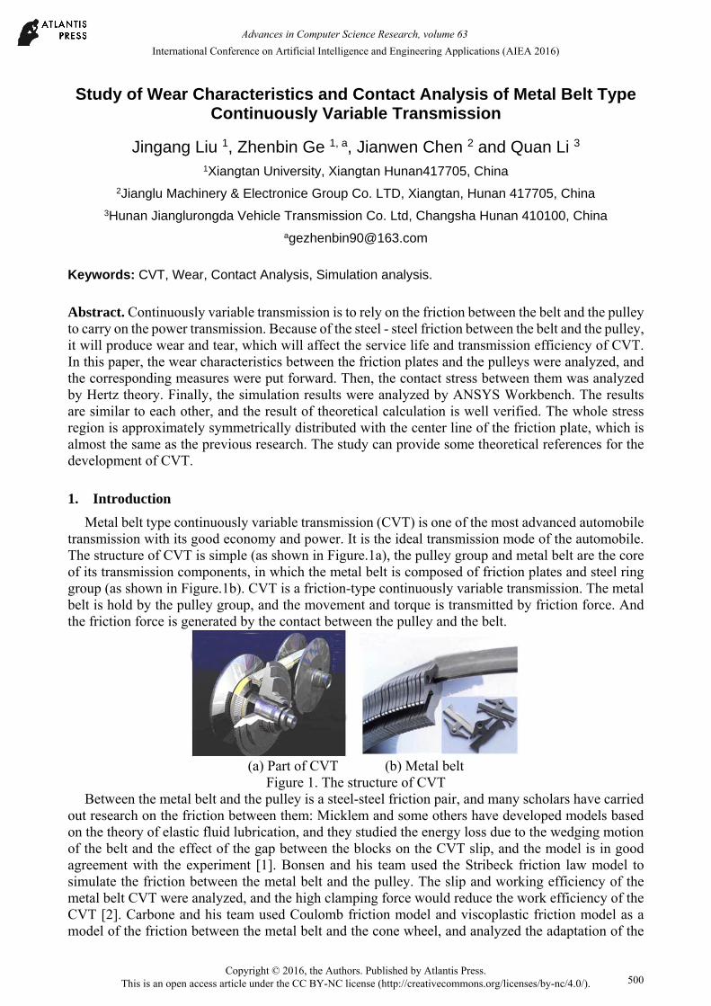
Metal belt type continuously variable transmission (CVT) is one of the most advanced automobile transmission with its good economy and power. It is the ideal transmission mode of the automobile. The structure of CVT is simple (as shown in Figure.1a), the pulley group and metal belt are the core of its transmission components, in which the metal belt is composed of friction plates and steel ring group (as shown in Figure.1b). CVT is a friction-type continuously variable transmission. The metal belt is hold by the pulley group, and the movement and torque is transmitted by friction force. And the friction force is generated by the contact between the pulley and the belt.
(a) Part of CVT (b) Metal belt
Figure 1. The structure of CVT Between the metal belt and the pulley is a steel-steel friction pair, and many scholars have carried
out research on the friction between them: Micklem and some others have developed models based on the theory of elastic fluid lubrication, and they studied the energy loss due to the wedging motion of the belt and the effect of the gap between the blocks on the CVT slip, and the model is in good agreement with the experiment [1]. Bonsen and his team used the Stribeck friction law model to simulate the friction between the metal belt and the pulley. The slip and working efficiency of the metal belt CVT were analyzed, and the high clamping force would reduce the work efficiency of the CVT [2]. Carbone and his team used Coulomb friction model and viscoplastic friction model as a model of the friction between the metal belt and the cone wheel, and analyzed the adaptation of the
International Conference on Artificial Intelligence and Engineering Applications (AIEA 2016)
Copyright © 2016, the Authors. Published by Atlantis Press. This is an open access article under the CC BY-NC license (http://creativecommons.org/licenses/by-nc/4.0/).
Advances in Computer Science Research, volume 63
500

two models [3]. The metal belt and the pulley is steel - steel friction, and affected by temperature, load and other factors, there will tend to cause wear of the metal belt, particularly the friction plate. Wear will affect the service life of the metal belt and pulley in the CVT. Hence, it has very important practical significance to analyze the wear of the friction plate. In this paper, the wear characteristics between the friction plates and the pulleys will be analyzed, and the contact stress between them will be analyzed by Hertz theory and ANSYS Workbench software.
2. Analysis of Wear Characteristic
For the metal belt continuously variable transmission (CVT), its wear mainly comes from the following aspects: a. wear caused by the relative motion between the steel ring group; b. wear of friction plate on steel rings due to different speed; c. the contact between friction plate and the pulley. Wear will affect the service life of the metal belt and pulley in the CVT. After the wear and tear of the friction plate, due to uneven stress, it may also cause the fracture of the metal ring, and at the same time, the surface of pulley may be destroyed by the broken debris of the friction plate. The wear, which caused by the contact of friction plate and the pulley, is the most serious, because the power is mainly transmitted by the friction plate and the pulley. The main wear types are contact fatigue wear and adhesive wear, and there are also other type wear that caused by the impact and extrusion. 2.1 Adhesive wear
As the positive pressure between the friction plate and the pulley is very large, there exists a boundary lubricating oil film between the friction plate and the pulley, and a large number of asperities between the friction surfaces of the friction pair are in contact with each other, which is the cause of bond and fusion welding. When there is sliding, shear fracture will occur at the bonding and welding points, which will promote the formation of adhesive wear. For adhesive wear, the amount of wear is generally predicted by the Archard model or the correction model [4].Figure 2 shows the Archard wear model.
(a) Forming sticking pointed (b) Destroy sticking point
Fig. 2 Archard wear model General expression of Archard wear model:
H
dLdPKdV
(1)
Its deformation formula:
dtH c
bPaKW (2)
where V is the wear volume, P is the normal pressure between the friction plate and the pulley contact surface, L is the tangential relative sliding distance between the friction plate and the pulley, H is the hardness value, K is the adhesive wear coefficient, W is the wear depth, v is slip velocity, a, b, c is the standard constant.
The Archard model shows that the factors affecting wear are friction-pair material, pressure, and sliding distance (slip velocity), so it is possible to use the following measures to reduce the adhesion wear for the CVT with the aid of the parameters involved in the model: a. changing friction pair material of belt wheel and metal belt; b. control the PV value between the metal belt and the pulley pair; Since the pressure is a key factor in achieving effective frictional torque. Therefore, in order to reduce the pressure, we must start from the structure and surface characteristics, so that under the same pressure, we can get a larger effective friction torque. c. we can add oily and extreme pressure
Advances in Computer Science Research, volume 63
501
additives to lubricating oil ,which will contribute to achieve full complement of lubricating oil, and effectively establish the lubricating oil film and improve adsorption capacity of the lubricating oil. 2.2 Fatigue wear
The working environment of CVT is very bad, which is full of high speed and high pressure. In the process of working, the metal belt must be constantly squeezed out and squeezed into the pulley. Under the action of cyclic variation of contact stress, the fatigue spalling of the material is formed, which can occur even under the condition of full film lubrication. Fatigue wear may lead to wear and tear of the friction sheet. Due to uneven stress, it may also cause the fracture of the ring, and the friction piece of the broken debris will also cause damage on the surface of the pulley. In order to reduce the fatigue wear, we can change the friction material, which will contribute to improve the depth of metal belt and pulley friction surface hardness and hardened layer. And we can also improve the accuracy of the control system, so that the metal belt cutting in and cutting out the belt wheel will be smoother. 2.3 Impact and extrusion wear
When the ratio of CVT is changing, the metal belt is moving along the pulley under the action of the pressure of the belt wheel. The relative motion caused by this kind of extrusion makes the lubricating oil film rupture, and it must have a scratch on the surface of the pulley. At the same time, when the metal belt is cut into the pulley with high speed, it is bound to have an impact on the surface of the belt pulley. In view of this type of wear, the friction coefficient of the metal belt and the pulley can be reduced by decreasing, and the related factors of the metal belt and the pulley control system can be improved.
In addition, due to the frequency of use of vehicle speed is not the same, there will be more wear in the use of high frequency, and in the low frequency band, with a smaller wear, which makes pulley surface shape along the radial direction is uneven, The radial movement of the metal belt along the belt will become difficult, which will ultimately affect the speed change of the CVT.
3. Contact theory analysis
Due to the friction plate and the pulley cone is a pair of steel friction pair, the pressure between the two is relatively large. From the previous paper, it is known that both adhesive wear and contact fatigue wear are related to the contact stress between them. In order to have a deeper understanding of the wear of the friction plate, the contact stress between the friction plate and the pulley is analyzed.
The contact surface friction plate for pulley cone is very small, so it can be regarded as a rigid body. The contact between the taper surface of the pulley and the friction plate is in a straight line before the contact, so that the contact of the two can be regarded as the contact of two coaxial cylinders, one of which has an infinite radius. The radius of curvature of the friction plate side contact pointρ2 is infinite, the radius of curvature of the cone pulleyρ1 =R/sinα.
Contact analysis is done according to the Hertz contact theory, the calculation formula of contact stress is:
)2
221
1
121
(
1
EE
Lb
K nF nH
(3)
where Fn —Normal force between the friction plate and the conical surface of the pulley, the calculation formula is:
)2(cos
R
tFF n (4)
Kn—Equivalent curvature of belt wheel and friction plate, the calculation formula is: 2/11/1 K n (5)
Fα—Axial force of belt wheel; Lb—Length of side of friction plate; E1, E2—Elastic modulus of belt wheel and friction plate; μ1, μ2 —Poisson's ratio of belt wheel and friction plate;
Advances in Computer Science Research, volume 63
502
R—Working radius of belt wheel; t—Thickness of friction plate; —Angle between the straight edge of the friction plate and the line of the two wheel shaft; α—the taper cone angle of the pulley. The input torque of driving pulley is 160N.mm, the rotational speed is 6000r / min, the center
distance is 160mm, the metal belt length is 660mm, the taper cone angle of the pulley 11°, the speed ratio i = 2.35.According to the calculation formula and mechanics in reference [5], and the various parameters needed for the calculation were obtained, as shown in Table 1:
Table 1 parameter results summary
Name Fα Lb μ1 μ2 R Kn λ E1 E2 t Data 27560 6 0.28 0.31 31.5 0.006 15.4 212 208 2 Unit N mm mm ° GPa GPa mm The parameters from the above table were put into formula (3) to calculate, the final result is:
σH=159.14 N/ mm2 .
4. Contact simulation analysis
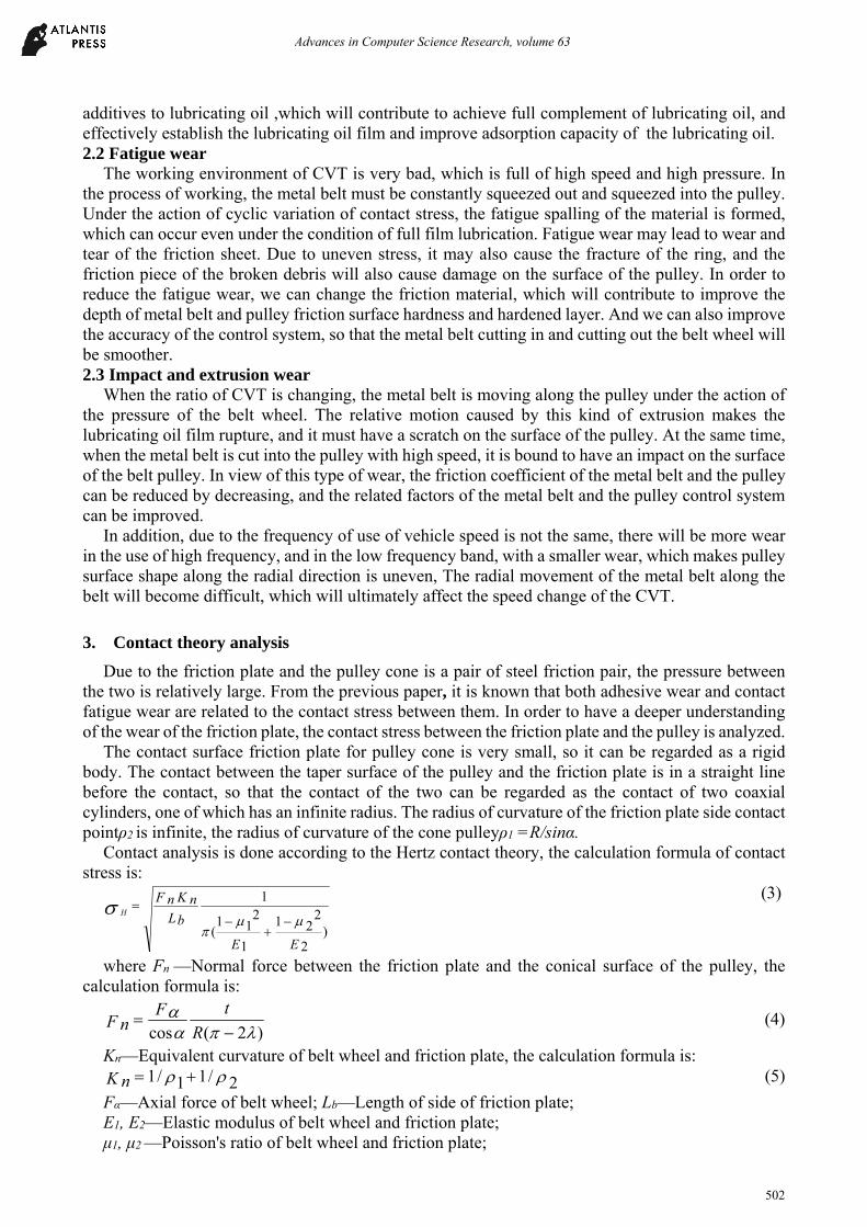
In order to verify the results of theoretical calculation, the contact stress between the friction plate and the belt wheel is simulated by using Solidworks 3D software and ANSYS Workbench software. 4.1 The process of Simulation analysis
Using Solidworks software to model the friction plate and the pulley. In order to save computing time and computing space, simulation analysis of contact will be done between a piece of friction and the pulley, at the same time, the model is simplified. The 3D model is shown in figure 3:
Fig.3 3-D model of CVT
4.1.1 Pre-processing of Simulation analysis In the workbench software, the 3-dimensional model is introduced, and the solid element is
selected before the analysis, and the material parameters are set. The basic parameters shown in the following table:
Table 2. Material property parameters Friction plate Pulley
Material name Rolling bearing steel 38CrMoAl Poisson ratio 0.31 0.28
Density(kg/m3) 7810 7800 Elastic modulus(GPa) 208 212
4.1.2 Other settings According to the selection principle of contact surface in the reference [6],the pulley cone is
selected as the contact surface, the side of the friction plate was selected as the target surface. The contact type is selected with “frictional”, the friction coefficient is set to 0.08, and the stiffness coefficient is set to 1. According to the need to set the size of the grid, and adjust the precision grade. Set fixed pulley to completely constraints; the moving pulley and friction plate are constrainted in Y, Z direction. And the load is applied to the moving pulley. 4.2 Results and discussions
After finishing the setting, run the software to analyze the model. The result is shown as below:
Advances in Computer Science Research, volume 63
503
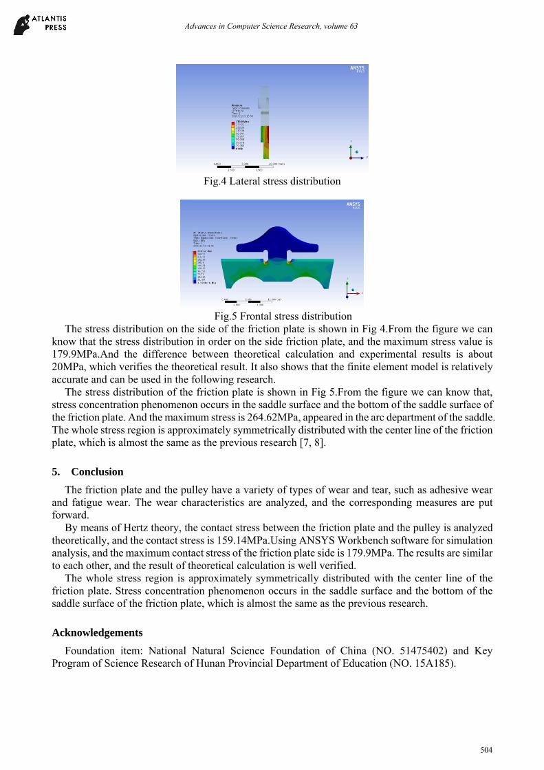
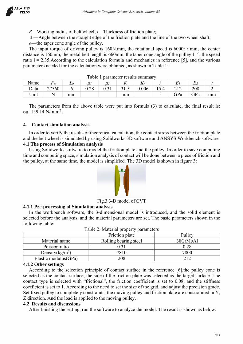
Fig.4 Lateral stress distribution
Fig.5 Frontal stress distribution
The stress distribution on the side of the friction plate is shown in Fig 4.From the figure we can know that the stress distribution in order on the side friction plate, and the maximum stress value is 179.9MPa.And the difference between theoretical calculation and experimental results is about 20MPa, which verifies the theoretical result. It also shows that the finite element model is relatively accurate and can be used in the following research.
The stress distribution of the friction plate is shown in Fig 5.From the figure we can know that, stress concentration phenomenon occurs in the saddle surface and the bottom of the saddle surface of the friction plate. And the maximum stress is 264.62MPa, appeared in the arc department of the saddle. The whole stress region is approximately symmetrically distributed with the center line of the friction plate, which is almost the same as the previous research [7, 8].
5. Conclusion
The friction plate and the pulley have a variety of types of wear and tear, such as adhesive wear and fatigue wear. The wear characteristics are analyzed, and the corresponding measures are put forward.
By means of Hertz theory, the contact stress between the friction plate and the pulley is analyzed theoretically, and the contact stress is 159.14MPa.Using ANSYS Workbench software for simulation analysis, and the maximum contact stress of the friction plate side is 179.9MPa. The results are similar to each other, and the result of theoretical calculation is well verified.
The whole stress region is approximately symmetrically distributed with the center line of the friction plate. Stress concentration phenomenon occurs in the saddle surface and the bottom of the saddle surface of the friction plate, which is almost the same as the previous research.
Acknowledgements
Foundation item: National Natural Science Foundation of China (NO. 51475402) and Key Program of Science Research of Hunan Provincial Department of Education (NO. 15A185).
Advances in Computer Science Research, volume 63
504
References
[1] J.D. Micklem, D.K. Longmore, C.R. Burrows. Modeling of the Steel Pushing V-belt Continuously Variable Transmission[J].Proceeding of the Institution of Mechanical Engineers, Part C:Journal of Mechanical Engineering Science 208(1)(1994)13-27.
[2] B. Bonsen, T. Klaassen, MVD Kgo, et al. Analysis of Slip in a Continuously Variable Transmission [J]. Proceedings of IMECE’03 2003 ASME International Mechanical Engineering Congress Washington, D.C., November 15–21, 2003 Proceedings of IMECE2003 2003 ASME International Mechanical Engineering Congress and R&D Expo November 15-21, 2003, Washi ngton, DC USA, vol. 72, No.2, Novermber 15-21, 2003, pp.995-1000.
[3] G.Carbone, L. Mangialardi, G.Manriota. Theoretical Model of Metal V-belt Drives During Ratio Changing Speed [J].ASME Journal of Mechanical Design 123(1)(2000)111-117.
[4] Gui C L. The archard design calculation model and its application methods[J]. Lubrication Engineering, 1990,(1):12-16.
[5] CHENG Nai-shi etc. Motor Vehicle Metal Belt Type Stepless Transmission--CVT Transmission Principle and Design[M].Beijing: China Machine Press,2007,9.
[6] CHEN yan-xia . ANSYS Workbench 15.0 finite element analysis from entry to proficiency [M]. Beijing: China, Electronic Industry Press,2015.
[7] LU Xiao-hu, CHEN Yue-ping, HE Wei-lian. Metal Belt Structure And Strength Analysis For the Metal Belt CVT[J]. Drive System Technique,2007. 21(2):20-27.
[8] SUN Dong-ye, QIN Da-tong, YANG Ya-lian. Analysis of Structural Strength of Key Components in a Metal V-belt CVT[J]. Journal of Mechanical Transmission,1998. 22(4):28-31.
Advances in Computer Science Research, volume 63
505