contact mechanics and wear simulations of hip … · contact mechanics and wear simulations ......
TRANSCRIPT

Acta of Bioengineering and Biomechanics Original paperVol. 16, No. 2, 2014 DOI: 10.5277/abb140212
Contact mechanics and wear simulationsof hip resurfacing devices using computational methods
MURAT ALI*, KEN MAO
School of Engineering, University of Warwick, Coventry, UK.
The development of computational and numerical methods provides the option to study the contact mechanics and wear of hip resur-facing devices. The importance of these techniques is justified by the extensive amount of testing and experimental work required toverify and improve current orthopaedic implant devices. As the demands for device longevity is increasing, it is as important as ever tostudy techniques for providing much needed orthopaedic hip implant solutions. Through the use of advanced computer aided design andthe finite element method, contact analysis of hip resurfacing devices was carried out by developing both three-dimensional and two-dimensional axisymmetric models whilst considering the effects of loading conditions and material properties on the contact stresses.Following on from this, the three-dimensional model was used in combination with a unique programme to develop wear simulations andobtain cumulative wear for both the acetabular cup and femoral head simultaneously.
Key words: archard wear law, biotribology, contact, finite element analysis, wear
1. Introduction
The introduction of hip replacements inspired thedevelopment and production of hip resurfacing de-vices, which are designed to reduce the volumetricwear rates of the implant devices and increase thelongevity of the implantation. These products are alsoaimed to be suitable for younger patients who requirea hip joint implant. The study of wear and surfacedamage has long been of a high importance for hipimplant research, development and manufacture. Inthe past, the majority of research was mainly focusedon the use of experimental in vitro testing simulatorsto predict the mechanical wear of the implant devicesusing international standards. With the increasingdemands on orthopaedic device companies to producevalidated and reliable implants which are safe forpatients, the necessity for new and improved tech-niques to be developed and support the engineeringactivities of such devices is imperative.
In addition to carrying out experimental simulatortesting, a viable alternative method for studying the me-chanical wear of hip resurfacing devices is through thedevelopment of computational contact and wear modelswhich can predict the wear of hip resurfacing devices [1].The complexity of wear mechanisms [2] makes modellingsuch problems more challenging than traditional stressand strain analysis using the finite element method. Toreduce the complexity of modelling wear mechanisms,a number of wear models have been proposed in the pastand the most widely used is the Archard wear model [3],which is still used today as shown by recent literature byRońda and Wojnarowski [4].
The objective of this study was to model the con-tact mechanics of hip resurfacing devices under nor-mal, edge loading and serve loading conditions, spe-cifically assessing the contact stresses of the hipimplant. Obtaining the contact stress results alongwith carefully assessing the boundary conditions andmaterial properties applied, formed the basis for de-veloping wear models which could be applied to as-
______________________________
* Corresponding author: Murat Ali, School of Engineering, University of Warwick, Coventry, CV4 7AL, UK. Tel: +44 24 7652 8193,fax: +44 24 7641 8922, e-mail: [email protected].
Received: July 19th, 2013Accepted for publication: November 14th, 2013

M. ALI, K. MAO104
sess the volumetric wear of both the femoral head andacetabular cup simultaneously, which has not beenconsidered in previous literature.
2. Materials and methods
A three-dimensional segmented hip resurfacingdevice model and two-dimensional axisymmetricmodel were developed based on the models used forcontact analysis by Ali and Mao [5], [6], with a cupand head bearing diameter of 50 mm and diametralclearance of 80 µm based geometrically on the modelsproposed by Udofia et al. [7]. The segmented modelallowed for the use of DICOM (Digital Imaging andCommunications in Medicine) bone scans to be pre-pared for an assembly with hip resurfacing implantmodels using Solidworks (Dassault Systèmes Solid-Works Corporation, Waltham, Massachusetts, USA)
Fig. 1. Segmented three-dimensional hipresurfacing finite element model
Fig. 2. Two-dimensional axisymmetric hipresurfacing finite element model
computer aided design. Through an associative inter-face with the commercially and academically availablefinite element analysis software Simulia ABAQUS(Version 6.10-1, Dassault Systèmes SolidWorks Cor-poration, Waltham, Massachusetts, USA), finite ele-ment assembly models were developed as shown inFig. 1 and Fig. 2.
A combination of hexagonal (C3D8I) and wedge(C3D6) finite elements were used for modelling theacetabular cup and femoral head components. Theseelements were selected based on their suitability forstudying the contact mechanics of hip implant de-vices. During the model meshing process, seedingtechniques were used including definitions of partseed sizes and edge seeding with directional bias todefine nodal points in areas of high contact stressessuch as edge loading and rim contact. Due to thegeometrical complexity of the femur and pelvic bonemodels, an automatic meshing algorithm was utilisedand based on tetrahedral elements. A sliding contactinteraction algorithm was defined with a nominalvalue of friction coefficient between the femoral headand acetabular cup of 0.16, which was based on thefriction factor of CoCrMo on CoCrMo (cobalt chro-mium molybdenum) in both bovine serum and syno-vial fluid [8].
Following on from the development of the three-dimensional model, the two-dimensional axisymmet-ric model allowed for a computational efficient com-parison of contact pressures and stresses of three dif-ferent vertical loading conditions. The ISO verticalloading of 3000 N (FI) and vertical load of 3900 N(Fy) were applied based on the peak load expected tooccur during the walking cycle. In addition to this,a stumbling load of 11000 N (Fs) was also considered,as these high vertical loads have been highlighted tooccur in vivo [9].
Both implicit and explicit finite element solverswere used to study the contact pressure during edgeloading conditions and rim contact between the femo-ral head and acetabular cup. The use of the implicitsolver allowed for an assessment of rim contact to bemade under lateral sliding of the femoral head leadingto edge loading rim contact. The explicit solver pro-vided a suitable numerical method for studying thecontact mechanics at the rim of the acetabular cupcaused by inferior and lateral microseparation leadingto edge loading. This type of edge loading contactoccurs during the re-engagement of the femoral headwithin the acetabular cup as a result of vertical load-ing at heal strike which is referred to as “pure” micro-separation in this study. The differences between bothimplicit and explicit techniques for engineering prob-

Contact mechanics and wear simulations of hip resurfacing devices using computational methods 105
lem solving has been concisely explained by Hare-wood and McHugh [10]. For an implicit analysis,a system of equations are required to be solved foreach analysis and displacement incrementation. Theglobal stiffness matrix K can be inverted to solve forincremental displacements, however, this is very oftena computationally intensive process, especially fornon-linear quasi-static problems involving contact.
Modelling normal contact conditions and lateraldisplacement edge loading between the femoral headand acetabular cup was achieved by reaching incre-mental equilibrium using the implicit method basedon the Newton–Raphson solver. For solving the finiteelement problem under laxity based edge loading theexplicit method was utilised. For laxity based edgeloading a microseparation distance between the femo-ral head and acetabular cup was first established, asthis is expected to occur during swing phase of thehuman walking gait cycle. Following on from this,contact would occur under the action of the verticalload during the stance phase. This is a complex contactcondition to model, therefore, a forward Euler integra-tion scheme was used, which can be used to solve com-plex contact problems. Overall, the explicit analysis isless computational intensive than implicit modelling aslarge stiffness matrices are not required to be inverted.
In order to simulate wear based on the ArchardWear model, the magnitude of linear wear depth hI
given by
)( 11
−=
−=∑ iii
n
iwI sspkh (1)
was defined at each node as being linearly propor-tional to contact pressure p, sliding distance s andwear coefficient value kw at each analysis increment i.The number of quasi-static finite element iterationswere defined from i = 1 to n. Wear coefficients wereassumed to be constant during bedding-in and steadystate phases as observed from experimental hip simu-lator studies, with the same approach applied withinprevious wear simulation models [1].
The gait loading boundary conditions have beenapplied based on the ISO (International Organisationof Standardization) standards developed for in vitrotesting, which simulate typical walking gait loadingprofiles as discussed by Bergmann [11]. This causescontact to occur between the hip implant bearingcomponents. The sliding distance is determined by thephysical sliding between the bearing components incontact, which occur through the relative angular dis-placement of the bearing. Therefore, ISO standardflexion-extension and inward-outward rotations aremodelled as kinematic boundary conditions.
To calculate the sliding distance between the im-plant devices, two numerical methods were usedthrough a combination of the finite element outputdatabase and user defined interfaces. One of themethods involved calculating the magnitude of therelative sliding distance d between the two contactsurfaces and the other was based on the change incoordinate position of the femoral head during theangular displacement cycle
21
21
21 )()()( −−− −+−+−= iiiiii wwuud νν (2)
where u, v and w are the displacements in the x, y and zdirection. For both methods, the finite element iterationdefined the intervals at which the sliding distance wascalculated. Although the abduction-adduction angulardisplacement was not included in the contact slidingmodel due to modelling constraints, literature has shownthe wear rates from the assessments of in vivo retrievalimplants match wear rates from two-axis experimentalsimulator studies more closely than studies using three-axis simulators (three motion rig) [12]. All rotations havebeen applied about the centre point of the femoral head(Fig. 3), which was defined as the centre of rotation.
Fig. 3. Hip resurfacing contact and wear simulation modelwith angular displacements
The wear simulation method was developed usinga Python scripting interface along with the finite ele-ment model. Following the calculation of linear wearat each increment, the total wear hT is multiplied bythe number of cycles k before finite element remesh-ing occurs
∑=
=k
iIT hh
1
. (3)
The total cumulative nodal linear and volumetricwear was calculated and the results presented. Moredetail on the wear simulation process is provided inFig. 4. This is an alternative method to that previ-

M. ALI, K. MAO106
ously developed by other researchers using subrou-tines to simulate wear. The material models andmethodology for both the metal-on-metal CoCrMohip bearing implants and bone models are discussedwithin a previous study by Ali and Mao [5]. A sum-mary of the nominal materials model values are pro-vided in Table 1, where EF and EP are the equivalentelastic modulus values applied to the femur and pel-vic bone models, respectively.
Fig. 4. Python scripting wear simulation procedure
Table 1. Material properties for finite element modelling
MaterialElastic
modulus(GPa)
Poisson’sratio
Density(kg/m3)
EF 12.3 0.30 1900EP 6.1 0.30 1900
CoCrMo 230 0.30 8270
In addition to establishing isotropic and homoge-neous material properties for the pelvic and femurbone sections, more complex orthotropic and Houns-field based density greyscale material models werealso modelled. For the greyscale model, each finiteelement was defined with a value of density (ρ).Therefore, Poisson’s ratio (ν) and Young’s modulus(E) were defined as a function of density. The Houns-field unit (GS) is determined from
water
water1000μμμ −
×= xGS (4)
where the linear attenuation of water is given by µwaterand the coefficient of the substance being measured
is given by µx. The density and Young’s modulusvalues are determined from definition of the user de-fined coefficients aj, bj, cj and dj where j denotes thesubscripts a, b and c
GSba aa +=ρ , (5)
⎥⎥⎥
⎦
⎤
⎢⎢⎢
⎣
⎡
⎥⎦
⎤⎢⎣
⎡+
+=⎥
⎦
⎤⎢⎣
⎡
c
b
c
c
ccc
bbb
dbadba
Eρ
ρν
1
00
. (6)
To determine if obtaining an equivalent modulusvalues for each patient specific scanned femur modeland pelvic model should be repeated, a parametricstudy was carried out by varying bone elastic modulusvalues. Firstly, the same elastic modulus was appliedto both the femur and pelvis, this was varied between3 GPa to 25 GPa. Then a separate segmented bonemodel was assembled with the femoral head and ace-tabular cup components, the elastic modulus was variedindependently between values of 3 GPa and 30 GPa.This provided an assessment for the relative materialproperties of the femur and pelvic bone models. Bycarrying out this analysis, the effect of bone materialproperties on the contact pressures and stresses wereassessed.
3. Results
3.1. Contact mechanicsof normal, edge loading
and severe loading conditions
The variation of maximum contact pressure, vonMises stress and principal stress against the femurand pelvic bone elastic modulus is provided in Fig. 5.A relative bone elastic modulus was applied betweenthe femur and pelvis, the contact pressure and vonMises stresses are shown in Fig. 6. Along with changeof contact pressure caused by different values of elas-tic modulus, any difference in contact pressure mag-nitude between the two graphs was also due to the de-velopment of the segmented model being repeated tocheck for any model errors, and assess the sensitivityof the geometry and assembly differences on the con-tact pressure and stress results. Although both three-dimensional segmented hip implant models werebased on the same DICOM bone model data, loadingconditions and implant devices, there was a difference
Contact mechanics and wear simulations of hip resurfacing devices using computational methods 107
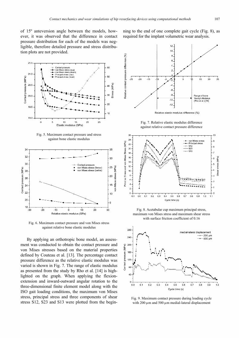
of 15º anteversion angle between the models, how-ever, it was observed that the difference in contactpressure distribution for each of the models was neg-ligible, therefore detailed pressure and stress distribu-tion plots are not provided.
Fig. 5. Maximum contact pressure and stressagainst bone elastic modulus
Fig. 6. Maximum contact pressure and von Mises stressagainst relative bone elastic modulus
By applying an orthotropic bone model, an assess-ment was conducted to obtain the contact pressure andvon Mises stresses based on the material propertiesdefined by Couteau et al. [13]. The percentage contactpressure difference as the relative elastic modulus wasvaried is shown in Fig. 7. The range of elastic modulusas presented from the study by Rho et al. [14] is high-lighted on the graph. When applying the flexion-extension and inward-outward angular rotation to thethree-dimensional finite element model along with theISO gait loading conditions, the maximum von Misesstress, principal stress and three components of shearstress S12, S23 and S13 were plotted from the begin-
ning to the end of one complete gait cycle (Fig. 8), asrequired for the implant volumetric wear analysis.
Fig. 7. Relative elastic modulus differenceagainst relative contact pressure difference
Fig. 8. Acetabular cup maximum principal stress,maximum von Mises stress and maximum shear stress
with surface friction coefficient of 0.16
Fig. 9. Maximum contact pressure during loading cyclewith 200 μm and 500 μm medial-lateral displacement

M. ALI, K. MAO108
The difference in contact pressure between apply-ing the vertical loading magnitudes of Fy and FI wasobserved to be 18%, however the difference increasedfurther when lateral edge loading boundary conditionswere applied. To be consistent with experimentalsimulator testing methods, the range of lateral displace-ments were applied between the ranges of 200 μm and500 μm, the results in Fig. 9 show the maximum con-tact pressure during a single ISO gait loading cyclewith lateral microseparation applied throughout theloading cycle.
Results discussed above were based on a nominalcup inclination angle of 45°. By changing the inclina-tion angle and anteversion angle, the effect on contactpressure and von Mises stress was assessed using thethree-dimensional head and cup models without thebacking of the pelvic and femur bones to obtain resultswith increased computational efficiency. The maxi-mum contact pressure and von Mises stress at varyingcup inclination angles and anteversion angles are pro-vided in Fig. 10.
Fig. 10. Maximum contact pressure and von Mises stressagainst varying cup inclination angle and anteversion angle
The kinematics of “pure” microseparation wasmodelled to study laxity based edge loading of hipimplants under contact. Following hip bearing micro-separation, laxity of the hip joint is present as dis-cussed in Section 2. By running an explicit model andapplying a vertical load of 3900 N, relocation of thehip joint was observed whilst being able to assess thecontact during this relocation analysis step. At a cupinclination angle of 45° contact initially occurred atthe rim of the acetabular cup. The maximum contactpressure observed was 341 MPa and no contact wasobserved below the rim of the acetabular cup, i.e.,the rim radius. When the cup inclination angle in-creased to 60° the maximum contact pressure in-creased to 646 MPa.
From the two-dimensional axisymmetric model,the maximum subsurface stresses were obtained forboth the acetabular cup and femoral head componentsunder FI, Fy and Fs vertical loading conditions. Themaximum stresses occurred below the surface ofcontact in all but one of the cases. It was only whena stumbling load was applied that the maximum stressoccurred at the base of the head component. The maxi-mum values of shear stress τxy and maximum σx, σyprincipal stress are provided in Table 2 and Table 3.
Table 2. Acetabular cup maximum stresses under vertical loads
Load Max. shear stress(τxy) MPa
Principal stress(σx) MPa
Principal stress(σy) MPa
FI 3.4 –19.8 –49.6Fy 4.6 –25.5 –64.5Fs 14.5 –69.6 –139.9
Table 3. Femoral head maximum stresses under vertical loads
Load Max. shear stress(τxy) MPa
Principal stress(σx) MPa
Principal stress(σy) MPa
FI 7.2 –37.1 –32.1Fy 9.5 –49.7 –39.8Fs 27.4 –135.2 –160.1
3.2. Wear simulations
The volumetric material loss due to mechanicalwear under flexion-extension, internal-external rotationand ISO gait loading conditions were recorded for boththe acetabular cup and femoral head simultaneously.By using the sliding distance algorithm method to de-termine the contact sliding distance and when applyinga wear coefficient value (1.0 × 10⁻¹⁰ mm3/Nm) to thewear model, the volumetric wear rates were 1.5 mm3 permillion cycles for the femoral head and 2.6 mm3 permillion cycles for the acetabular cup. A comparisonbetween using the sliding distance output methodol-ogy and the coordinate output methodology was car-ried out. The difference in wear rates between usingeach method for the same segmented hip resurfacingmodel under angular displacement was 3.5% overone million cycles. For a wear simulation developedfor 10 million cycles, the wear code was adapted tosimulate and reflect long term wear, whilst consid-ering the occurrence and trend of the wear observedexperimentally. Achieving this result required thesetup and development of a numerically stable modelto manage the altering finite element mesh occurringduring the wear simulations. A cumulative volumetricwear loss of material for both the femoral head andacetabular cup is presented in Fig. 11, as well as the

Contact mechanics and wear simulations of hip resurfacing devices using computational methods 109
presentation of the volumetric wear loss of the femo-ral head against wear coefficient value over one mil-lion cycles (Fig. 12).
Fig. 11. Femoral head and acetabular cup volumetric wearover 10 million cycles
Fig. 12. Volumetric wear of the femoral headat different wear coefficient values
4. Discussion
The three-dimensional and two-dimensional hipresurfacing models have both provided unique andspecific models for assessing the contact mechanicsusing a range of materials models and boundary con-ditions. By modelling bone material properties asisotropic, orthotropic and density based, it was deter-mined that the contact pressure was insensitive to theintricacies associated with complex material models
and relative differences in material models betweenthe femur and pelvic bone sections. For low values ofbone elastic modulus the principal stresses and vonMises stresses varied more greatly than the stress valuesat an elastic modulus greater than 5 GPa. The angulardisplacements and ISO loading conditions applied tothe three-dimensional segmented model provided theoption of calculating the sliding distances along withthe application of variable loading using computa-tional methods. The contact pressure between thefemoral head and acetabular cup, as well as the shearstresses of these contact loadings matched the trendand profile of the input time dependant loading curveapplied during the walking cycle.
By using the finite element method, the full rangeof lateral displacements typically applied during mi-croseparation based hip simulator tests was modelled.The difference in maximum contact pressure observedwhen applying 200 μm and 500 μm was shown. Al-though ISO loading was applied, the contact betweenthe bearing surfaces was dominated by edge loadingdue to the lateral displacement of the femoral head.This is shown by the contact pressure profile through-out the cycle not conforming the ISO gait loadingprofile.
The two-dimensional axisymmetric model allowedfor an efficient assessment of the contact pressure andstresses at the surface and sub-surface of the bone andhip resurfacing implant devices. By applying the FI,Fy and Fs vertical loads, increase in stresses were ob-served for both the femoral head and acetabular cupimplant components as the vertical load increased.
A close comparison of sliding distance was obtainedby using the two different sliding distance calculationmethodologies, which provide an increased level of con-fidence in the validity of the wear results. Both methodsprovided a valid platform for assessing the volumetricwear between hip resurfacing devices using the finiteelement method with a custom scripting interface. Thethree-dimensional hip implant wear model providedvolumetric wear results for both the acetabular cup andfemoral head simultaneously, which has not been con-ducted before in previous studies. Although not com-pared extensively in previous studies, the results showthe volumetric wear of the acetabular cup to be higherthan for the femoral head which is also observed ex-perimentally from cyclically simulated hip implant com-ponents [15]. A linear increase in volumetric wear wasobserved as the wear coefficient value increased, whichshows the effect of the wear factor on the loss of materialand highlights the importance for further study. Theadvantages of using the scripting method for developinghip implant wear simulations over previously published
M. ALI, K. MAO110
methods using subroutine based simulations include lessrestrictions on element types and contact algorithms, aswell as allowing an option for applying the wear modelto both the acetabular cup and femoral head componentssimultaneously.
Overall, this study had demonstrated the use ofcomputational and numerical methods for studying thecontact mechanics of three-dimensional and two-dimensional axisymmetric hip resurfacing models. Thiswas then extended to develop wear simulations to ob-tain the volumetric wear rates of hip implant devicesunder contact, angular displacement and variable load-ing conditions. This study has shown the possibility ofusing a Python scripting interface to simulate the volu-metric wear loss by applying the Archard wear modelto hip implants, and therefore model the long term per-formance of implant devices beyond current ISO stan-dards for experimental simulator testing. This has beenachieved whilst establishing the appropriate boundaryconditions and material properties to be applied to thecomputational implant models. Further work includeslonger term computational wear simulations with theinclusion of edge loading during the loading cycle.
Acknowledgements
This work was supported by the EPSRC (Engineering andPhysical Sciences Research Council).
References
[1] LIU F., LESLIE I., WILLIAMS S., FISHER J., JIN Z., Development ofcomputational wear simulation of metal-on-metal hip resurfacingreplacements, Journal of Biomechanics, 2008, 41 (3), 686–694.
[2] MENG H., LUDEMA K., Wear models and predictive equations:their form and content, Wear, 1995, 181–183 (2), 443–457.
[3] ARCHARD J.F., Contact and rubbing of flat surfaces, Journalof Applied Physics, 1953, 24(8), 981–988.
[4] ROŃDA J., WOJNAROWSKI P., Analysis of wear of polyethylenehip joint cup related to its positioning in patient’s body, Actaof Bioengineering and Biomechanics, 2013, 15(1).
[5] ALI M., MAO K., Contact analysis of hip resurfacing devicesunder normal and edge loading conditions, IAENG SpecialIssues Journal, 2012, 20(4), 317–329.
[6] ALI M., MAO K., Modelling of hip resurfacing devicecontact under central and edge loading conditions, Lec-ture Notes in Engineering and Computer Science Pro-ceedings of The World Congress on Engineering, 2012,20(4), 2054–2059.
[7] UDOFIA I.J., YEW A., JIN Z.M., Contact mechanics analysisof metal-on-metal hip resurfacing prostheses, Proceedingsof the Institution of Mechanical Engineers Part H – Journalof Engineering in Medicine, 2004, 218, 293–305.
[8] SCHOLES S.C., UNSWORTH A., GOLDSMITH A.A.J., A fric-tional study of total hip joint replacements, Physics in Medi-cine and Biology, 2000, 45(12), 3721.
[9] BERGMANN G., GRAICHEN F., ROHLMANN A., BENDER A.,HEINLEIN B., DUDA G., HELLER M., MORLOCK M., Realisticloads for testing hip implants, Bio-medical Materials & En-gineering, 2010, 20(2), 65–75.
[10] HAREWOOD F., MCHUGH P., Comparison of the implicit andexplicit finite element methods using crystal plasticity, Com-putational Materials Science, 2007, 39(2), 481–494.
[11] BERGMANN G., DEURETZBACHER G., HELLER M., GRAICHENF., ROHLMANN A., STRAUSS J., DUDA G., Hip contact forcesand gait patterns from routine activities, Journal of Biome-chanics, 2001, 34(7), 859–871.
[12] FIRKINS P., TIPPER J., INGHAM E., STONE M., FARRAR R.,FISHER J., Influence of simulator kinematics on the wear ofmetal-on-metal hip prostheses, Proceedings of the Institu-tion of Mechanical Engineers, Part H, 2001, 215(1), 119–121.
[13] COUTEAU B., LABEY L., HOBATHO M.C., VANDER SLOTEN J.,ARLAUD J.Y., BRIGNOLA J.C., Validation of a three dimen-sional finite element model of a femur with a customized hipimplant, Computer Methods in Biomech. & Biomed. Eng.,1998, 1(1), 77–86.
[14] RHO J.Y., ASHMAN R.B., TURNER C.H., Young’s modulus oftrabecular and cortical bone material: Ultrasonic and mi-crotensile measurements, Journal of Biomechanics, 1993,26(2), 111–119.
[15] MANAKA M., CLARKE I.C., YAMAMOTO K., SHISHIDO T.,GUSTAFSON A., IMAKIIRE A., Stripe wear rates in aluminaTHR – Comparison of microseparation simulator studywith retrieved implants, Journal of Biomedical MaterialsResearch Part B – Applied Biomaterials, 2004, 69(B),149–157.