study of the method of geometric mean distances used in
TRANSCRIPT

Scholars' Mine Scholars' Mine
Masters Theses Student Theses and Dissertations
1947
Study of the method of geometric mean distances used in Study of the method of geometric mean distances used in
inductance calculations inductance calculations
Harold Lockwood Seneff
Follow this and additional works at: https://scholarsmine.mst.edu/masters_theses
Part of the Electrical and Computer Engineering Commons
Department: Department:
Recommended Citation Recommended Citation Seneff, Harold Lockwood, "Study of the method of geometric mean distances used in inductance calculations" (1947). Masters Theses. 6747. https://scholarsmine.mst.edu/masters_theses/6747
This thesis is brought to you by Scholars' Mine, a service of the Missouri S&T Library and Learning Resources. This work is protected by U. S. Copyright Law. Unauthorized use including reproduction for redistribution requires the permission of the copyright holder. For more information, please contact [email protected].

TU Y TEE H
U ~D I I
OF G
CT
BY
H. C DOD E ~ • Jr.
SCHOOL OF
1 P
THESIS
ubm1tt d to the faculty of th
ES D 'TAL;U GY OF 'THE UNIV, ITY OF I S URI
tial fulf111.m nt of the ork ruir d for the
degr e of
T R 0 SelENe IN L CTRIC L ~~GIN ERr G
Rolla, i sour!
1947
p,prov

TAB 0 CONTENTS
PagI TRODUCTION•••••••••••••••••••••••••••••••••••••• 1
CHAPTER I. DERrV .TIO S'........................... 2
1. D fin1tlon •••••••••••••••••••••••••••••• 22. n tic F1 ld round Long Cylindrical
Con uctor •••••••••••••••••••••••••••••• 33. Int rn 1 Flux L1niag s ••••••••••••••••••• 7
• Ext rn 1 Flux Linkag s ••••••••••••••••••• 85. Ind et nc, in Any Cylind leal ir ••••••• a6. ConY r ion to th CG Sy t m••••••••••••• 97. Induct nc of a Singl lr in T rm of
Geom trlc n Radiu •••••••••••••••••• 108. lux Lin of ~Pa 11 1 lr 8 •••••••• 129 • G om tria ,n D1 tanc s................. 14
9
45
"lrcnltn
• • • • •• • • • • • • • • • • • • • • • • • • • • • • • • • • • • •Con ua or Phs
•••••••••••••••••••••••••••••••••••
............ ~ .
••••••••••••••••••••••••••••••••••• 44Circuit•
•
5.
1

7. ~hr.e Phase Double Circuit Symmetrical Line ••• 508. Thre Phase Double Circuit Unsymmetrical Line. 529. Three Phase Multlcircu1t Line Flat. Spaced••••• 55
SUMMARy•••••••••••••••••••••••••••••••••••••••••••••••• 72
APPEliDIX. • • • • • • • • • • • • • • • • • • • • • • • • • • • • • • • • • • • • • • •• • • • • •• 74
BIB.LIOGRAPHY••••••••••••••••••••••••••••••••••••••••••• 84
.LIS! OF ILLUSTRA!IONS •••••••••••••••••••••••••••••••••• 111
11

LIST OF ILIDSTRATI NS
H H Conductor •••••••••••••••••••••••••• 31
S n Strand CO'J1ductor................. 23
A Typical A.O.S.R. C bl ••••••••••••••• 33
Typical str nd d Oonductor ••••••••••• 22
Uneymm tr1 1 Line......... 8
of .C.S.R. str ndlng••••••• 21
Conductor •••••••••••••••••••••• 28
80m Typ
'PageFlux Lin 'g a •••••••••••••••••••••••••• 4
N~Parallel ires Carrying Curr nt •••••• 11
T 0 Cylindrical on~Magn.t1c Parall 1Conductor of Irr gular S ctio ••••• 14
Three Pha
SJrlYUn tria 1 Single Phase Daubl Circui tLin ••••••••••••••••••••••••••••••••• 45
Un ymm trical Doubl ·Clrou1t SinglePh s Line ••••••••••••••••••••••••••• 49
A Thre P e Double Circuit Symrne ri..cal Lin ••••••••••••••••••••••••••••• 50
Un ymm trical bree Phas" Dou le CircuitLlne ••••••••••••••••••••••••••••••••••53
Anacon
Flgur 1.
F1gu.re 2.
Figu.r 3.
Figur 4.
F1g\lr8 5.
Figur 6.
Figu.r 7.
'lgure 8.
Flgu.re 9.
F1gu.r 10.
:Fieur 11.
igur 12.
Flg'tlre 13.
Flgu. 14.
F1gur 15 • S1' Cirouit Three Phase Line ••••••••••• 56
Figure 15b. Six: Circuit Three Phase Lin ••••••••••• 60
Flgur 15c. 31 Circuit hre Pha' L1n ••••••••••• 64
111

1
INTRODUCTION
The object of this thesis 1s to study the me,thod of
geometric mean distances as applied in the calculation of
inductances of transmission line conductors and of multi-
circuit transmission lines.
The thesis will cons1s't ot: (a) the derivation .of some
of the basic theorems and equations to 'b,e used t (b) the use
of these theorems and equations in calculating the geometric
mean distances of different transmission 1148 conductors,
and (0) practical application of geometric mean distances
applied in the calculation of eqUivalent induotance of mult1
circuit transmission lines.
The method of geometric mean distances as applied to
individual conductors of single circuit lines 1s widely used
on a well established basis. Methods and rules for appli~
cation to mult101rau1t lines of various types are not so
11 formulated. It 1s hoped that these latter rules may
be bett r developed in this thesis.

CHAPTER I
DERIV, TIO S
The inductanoe of a transmission line depends upon the
material, dimensions, and configuration of the ires them
S .lves, long With the spacing bet een them; the calculation
of th inductance 1 based on the follo ing fundam ntal
d f'1n11iions and e uation ):./
1. The coef~1c1ent of inductanoe of a
circuit of one ingl turn m~ be defined With the aid of
the fundam nt 1 quation of induced voltag ,
= ~ 41: A ('1)- t ~ ••••••.••••••••••••••••••.
1 th olt ge of elf induction d L 1s th induc-
t noe 1 h nr1 • The ymbol tor flux linkages 1s A and
1 d tin d a th umm c ion of all th 81em nt· of flux
lt1p11 'by th fr ct,iOll of th total eurr nt link d by
ach. an (1) l' the curr nt in amp res. An mp re 1 th
con tant curr n hich, ma1nt ined in t 0 straight eonduc
to ot 1nflnit length 8parated by a dlstanc of on meter
produc' b t n th conductors fore ·of 2 x 10" aules
t.
ad

per meter of length. Solving equation (1) for L and re~
rr ng1ng, the equation becomes
L = dA di • di\err -n- --n- henr18s •••••••••••••••••• (2)
L, the inductance, 18 defined &8 the rate of change of flux
lamg,.·. '1th current, or When there is no extraneous flux
set up by other means than the circuit 1tself. the. inductance
1B henries 1s: a.etined • qual to the total numb r ot flux
linkages divided by the current.
2. gnet1e Fl1d around _ ~ Cylindrical Conductor.
It may be shown experimeIltally lih iron :r11ings and by use
of a compass needle that in long cylindric 1 ire of radius
(a) carrying a steady current of I amperes, hlch 18 assumed
un1fo ~ d1atr1bu'ed over its cross sect1onl/. there ar
set up lin.. of flux arrang.~ In conoentric circle round the
1rs&nd a180 1th1n the ire. Figure 1 represents the conc••~
':rlc l1as of flux of thickDe 8 dx 't dl tana. x from the
cent r. both ins1de and outside of the Wire. From the bOTe it
tollo s that at a~ fixed radius from the cent·r of the wire to
a point outs14e the 1re the flux dens!ty Band magnt1s1ng
re uniform. ·long the e18m n' ~ flu% p th outs1 e
uapi10n of uniform current den 1'7. ltAeugh noi17 corr ct, 1s s iisfactory ~or ov rh 4 p r clr u1t· •

Figure I.
.._-------_._-_._--------I II j
f t
Flux Linkages.

5
of th conductor of radius x meters and thickness <Ix th
gnetle i1 ·ld 1ntenslty H 1s equal to the total magneto-
motive force(DlDlf) F (in amp re... turns) diyided by the length
of path, hlch 1. 2 7f X.
PH = 2 ~ X a p re-tnrns per m tar.
Taking into consideration on turn of flux. F I ampere
tuD.s.Ther for •
H :II mp ,r ... turns per met .r •••••••••••••• (3)
The ~agnetl0 flux density B long this p th, 'h1ah 1 in free
8' c ,is qual to th gnet1c fild 1nt.nsi~ tim s space
perm b111ty- f..Jo • SJ C P rmeab111ty 1-'0 1s numerically
qual to the r tic b· t en flux density B and field intensity-? . ~6 1/
H in tree pac and 1', 4 rr 10 1.25' x 10 ~. By d,t1...
nltlon of flux en81ty.
B # fJo H :I 4 7f10' 2 ~ X
or th macD. tic fl, 11 ,1",.. out 14, th eOl1"nctor 1
-7B : ~X10 1
%,',b'r P' 'r u" r, 11 r •••••••••••• (4)
1:./ S _00 n "

6
Con ider no a tub' ot :flux of Infi.nl t 1 1 thick
Dess dx 1th1n the cy-11ndr1oal conductor as shown in Figure
I.' Th area contained inside this tub 1s 1TX2 • Th cur..
r n hich flows lthln th1 area is I an 1s equ 1 to2 x 1/
I --.:2 SSUDling uniform eurrent den 1t7 - h re I Is th
tot 1 currnt hleh flo in th total ar a ~ 2 ~4 (
18 th radius of th cylindrical oonductor. Ther tor t by
an 10 y to equ t10n (3)
H p r -turn per m t r
and iDee t
th refor t H p r • urns p r met r.
in thi case 1 equ 1 to fJR h r
bl11tyof the conductor and f~' non-
1 1 practically const nt, but tor m gn tic
fA 1
gnt1
1& . ar1 s Ith th ~p of tal, h treatm -nt,
temp r tur, te. In treating the latt rnalytically 1t
n a erag alu o~ p rmeab111ty, und r
1
th
con 1tlon t for h hole lr. R t1 p rmeab111ty
qu 1 () -id- 0 r 1 th ra 10 of ctual p rmeab1.11ty- andiJo
of ire· pac. Tn r for t for th flux d.nslty
ootno. 1, .g 3.

7
_ 2~X10-7 IXB - . 2 J ~elative permeability
8,
or ••bars per square met r •••••••••• (5)
which takes care of the flux d ns1ty with1n the wire itself.
Referring back to Figure 1. the fluxoutalde of th.
conductor links 1th all the current :rio Ing in the conductor,
or Inother ords the:re 18 total flux linkages 2.£ external
flux linkages. The flux within the condue~or itself does not
link With all of the total :un '4'; thus thi. flux forms
partial~ l1nkag • '~ 1n) raal~ l1Diac8••
In calculating th induct nee it 1_ nee. &r7 to d.ter~
mine the external flux 11nkag 8 and a180 an' quiTalent value
for the partial flux linkages.
3. Int rnal !!y Linkages. From equation (5) the flux
density du to ~he flux with1n the wire 1s
B :: 2:~lO""'l IX2
ebera per square meter.
!he flux within the elementary tube of radius x tor a unit
eter length of the conductor 1s
di\ •: 2 X I -IJ- x 10 'l d.x
&2 )./0
Sine,. thi8 flux links With the current only in a portion of%2
the total oonduc'or are.. <-;::r)' the equivalent partial flux
linJt:aae i\e 11l: & 41tferen\t 1 Incr _ent of the radiu.s dx 1s:

a
dx linkage. per aetar
~he total equivalent partial flux 11Dka.ge would be the sum
mation or integral of all the flux linkages bet en the limits
X • 0 to X =a. Thus,
4. Ext rnal~ Linkage.. hom .quat1 ,n (4:) the g..
net1c flux clena1't7 due to the total flux linkages ous1cle
the ~11 drlcal conductor of unit relative perm ab111i7 ,and
r ,ius (a) met • 18
Ba
!h _otal ext mal magnetic flux 11.nkag s troll (a) to a 41 ..
tanee (D) out,aide the eOtldue or p r meter 1, ,ngth of con,due,tor
18
A =
5. Il14uctano !!l A!!Z Cz11nclrlcallre~ Total flux
111lkaces are equal to _ 't 1 .quivalent partial flux linkages

9
plu total xternal linkage. ~heretore. combining equations
(6) and (7)
At = 10.7 I (2 In -E-+ 1 ~) •••••••••••••• (8}a -r f-io
'"
In uet nee 1 .,ual to flux l1Diag s divid d by the total
eurr,nt bT our pre 10us definition. H nee
L = ..7 D '1 11'-10 (2 In a-+ 211;) henri P l' ,t r •• (9)
Look1n t quatiol\ (9 ) it 1 n that the inductance
is the urn of t o t • th trm (2 In ~) d pend upon,
the 1 • and spacing of th ire t and th se ond t rm de-
penas upou th p eabl11ty of the, 1r s. In ordinary OY r~
h 'ad tranam1s ion lin conductor t th second term 1s 11
00 pare 0 th, fir ·tt except in the ea hen th conduc ora
r mad ·f 1 n or ate 1. h re or , gr a t import nc c n
~ pl ee on prper p cing and siz of ires to obtain th
1 ast amount of induotance with mini um cost.
6. COD r ion !2. !a!.~ Sl' m.. '!h ala s1c inductance
f mula 1 q' len (9) hich 1
L : -7 (2 111 .JL + 1---2h nrl per eter

10
base4 on the MKS ystem ot un1t. here f.1 is the actual
permeability of the material and ?o 1s the space permeability~7 . 1/
whioh 1s equal to 4 1T 10 in the JlXS 8T81;ea of un!ta.- Rela-.
tive per eability ae previously- defined 1s ff:. In changing
to the eGa .yet m 81>&Ce peraleab111ty f-'o 18 equal to unity;
therefore, equation (9) becomes
L • 2 ln .lL + -1- abhelU1ie. prom per conductor
or
L :! (2ln : +-r-) lO-a henries per em perconduotor
, • Il1c1uatance.2.! ~ Siyle Wire .!! ferm 1£ Geo .tr1c
-ean Radius. '.k1ne the 0114 cylindrical w1re aho n 1n-- .
:Plpre 1 ant rapl c1ng it by an 1nfln1'1I!J1al13 ihin tub:. 80
that th ~ ar_ no internal flux l1nka£•• , haTe a conductor
whoae »a41ua (a) 1 known &8 the OM.•tr1c Me !1 Ra41us (cam).------........ -....- ------....Thl conduotor ha the ame 1n~.rnal inductance, the relative.,p rm ability of which 11111 be 10 in ~h. JIKS sTste. or
un!t7 1a ega and practical 87 'em. Sta.rting With qutloa
( 9) 11l tAl. fora
L : 10-'1 (2 In D + 2 1Jl ...i- + .~ .L)heul. 1m ter.., 110

11
ana &PP~1ng the GMR princ1ple t where by def1nit10. the GMR
o~ a conductor 1s the radius of an 1nflnlt1 111&117 thin tabe
with the same internal inductance a8 the conductor, the equa~
tloD becomes
L = 10"" (2ln D + 2 In.> henri•• per meter
wh re tho :first t ',:Pm. 18 the in4uc'anoo du to the flux from
th ra41u8 <a) out to a dietanc D, and the ••and term 1s
the Induetanee due to all the tlux Within the ra iU8 (a).
The above equation can be r1tten in the t 11oW1ng tor' :
L :I., . ])
2:.x lO( ln -.) henri per ••t.r•••••••• (ll)
Equation (11) 1s I portant because aausing unltol'm ca.rreni
dens!i;7'!/ 1 can be used tor ealculating the induotance of
allY' type of an Gve:rh.ad conductor, uch &s a stranded conductor,
III r ~ by us1 g the pro, r yalue of GMR.
c Den nnxex
Oac Db.....
a Dab
17 s. Fo'
ire. Can71· Current.

12
8. ~ Linkages .2! N-Parall 1 ires. In Figure 2
a gro'up of N--parallel ir s lsreprea nt d so that they earry
all of .th current of th oomplet circuit. X is a~ point
hose diet no from is greater than the distance from a
to ny 0 h r eon uotor in this system. Let it be required
to d·v 10: an equation tor th total flux linkage of N-parallel
ir s.
C' lling th current I a in conductor (a). and lth"the
1 of GMR.t he flux l1nka about conductor (a) due to 1ts
own curr n I a 1s from quatlon (11)
Aa :; 2:X10..7 In x: I a linkages per m t r •••••• (12)
h r Dax 1s th dl tanee from conductor (a) to point x.No th flux linkage in conduator (a). du to the cur-
I.-8n in othr on ( ) Of the r 'ma1nlng w1r b, e. and d
nd produc d 07 lin a of flux bet e n and x, are from qu
tion ('1) tor xt rnal flux linkages
AsK
=
DkX
i 2~;X10-'7 Ik ~., X
Ok a.
2:~lO-'7 Ik 1n~ ••••••••••••••••••••••• (13)
hr k t nd tor con no r b, 0, t • • • • • • • • •
Th1 q t10n um.e t d1 r of th conductors
r ry ing of the ire in the
e1r'ult ino th ion 1 nor th :P rtlal flux l1nkag

13
8ftect. !here 1 obviously ve~ little error introduced b7
th1s assumption.
The total flux linkages about conductor (a) are there-
o -7 I...Qg~ . Dbx ~x_i\at ::: L. X 10 ( a In~ + I b In Dloa + Ie In lJba +
· · · + Ih In gg~ ) (14)
Since lt wae a.Burned that the If conductors carry all of the
current,
IN =-Ia .. I b - Ie •••••• rln_l··~·~··········(15)
Substituting the value tor IX in equation 14 and eomblnlnc
the lOBar1thma the equation becomes
-1 (I , Dna ~ + I I Jlna Dbx +Aat == 2 x 10 a n GMRa • Dnx b n Dba· Dnx
I'
Dna Dnx ).......... + no a·~n-I en-\) Dnx
Now let X approach Int1l11ty 80 that DaX, 4bX a.,d DDX w111
approaoh lnt1nl'7 t thu the traC$10118 1n:volv1ag X w1l1 th ,n
approach unitT • a ll.1~. !heretore the actual total ~umber
ot linkage. about conduclor (a) 1s equal to
-7 I '~Lt~ I I Qnax + I f 8na )Aat == 2)(10 ( a n~+ b nOba + .... n-I n en-I)a

14
or,
+ · .. · · · · ·+ I h - r (\n D(~-Ila-Inoh )J
and then applying equation (15) based on Kirchkof~ls Law,
the above equation becomes finally,
· · · · · · ·+ In In o~a J linkages per meter .. (16)
The above equation 1s an important one because it forms
the basis from hich'1t 1s possible to determine the total
inductance' 'of any system of parallel conductors and is the
important step in the development of the widely used method
ot inductance calculation by Geometric~ Distances.
9. Geometric Mean Distances. Figure 3 represents an
zFigure 3. Two Cylindrical Non-Magnetic Parallel Conductors
of Irrgular Sectionse

15
irregular cross section of cylindrical non-magnetic conduc
tors X and Z. Let the cross sections of both and Z be
divided into an infinite number of infinit1simally small
parts respectively so that each part carries equal current
and, assuming uniform current density, is equal in size.
Let the current in X be I and the current in Z be .. I so that
X and Z conduatora make up a complete circuit. The currentI -I
in each small element ot X will be T a.nd of Z will be -,r: •
The elements in X will be numbered 1, 2. 3, ••••••••••••N.
~ow app~lng equation (16) Just as if the various elements
were cross sections of independent conductors, the number of
linkages about conductor 1 18
= 0 -7 I (I 1 I 1 12. x 1 N nGMR + n 021 + In 031 + .
, 1 ) I 1 1 1....+ 11 Dn - N (InDBl + ttl Db1 + ... + ltl On! )
The first part of the above term includes the contribution
of'the elements in X and the second set of terms 1s from all
the elements in conductor Z. The above equation by combin-
lng terms can be written
== 2 X 10⁻⁷ ~ In N Dat · Obi · OCt • • • • • On'GMRl· 021 .. D31
Similar expr a.ions may be wfitten for the flux linkages about

16
elements 2. 3, 4•••••••••••N of irregular conductors or
Nc-----------T VDaK· Dbk • DeM •••• OnK
2 x 10⁷*In V'GMRK ' 011< ' D2K
where K 1s any one of the elements in conductor x.No the sum of all the linkages about all the elements
from 1 to of conductor X will be equal to the number of
linkages about the entire conductor. However, it must be
r membered that one linkage about one of N equal elements
contributes only + o:t, the linkage' around the entire con
ductor. Therefor., summing up all of the equations for N
linkages and dividing that sum~ bY' the number of lements (N),
the equation become
-7 I [ ~DBi' 0 bl' Oct,·· Ont ~D8Z ' DkJ2.· DC2 .,. On2.At.ave ::: 2 x 10 N In\lGMRI ' Del' 031 + In "'GMR2' Die' D!z
+ + In " Dah • Dbn · DCt) ]
H •• • • • • • • • • (.17)~GM.Rn · Din· D2n
which can be wrltt n in the form
Atave :=
No let th number of 81em nt into hlah ach conductor
1 dlv1de4 pproach infinity. which in tnrn lets the numer
or of the quat10n ppro&ah the geometric me n distance

17
from one conductor to another. The denominator approaches
the geometric mean distance of conductor X to itself or
therefore equation' (17) can be written
"'\. .. 7 Dm I" a 2 x 10 I In. De linkag.sm.t.r•••••••• (18)
where Da equals to the geometric mean distance bet .en con..
ductora and where geometric mean is the nth root ot an n..told
procluot. Ds equals the ceometrle mean radius or self GIlD
of a single conductor ·or a group of parallel conductors such
as stranded conductors.
Solving equation (18) for L
L = + Ii 2 x 10⁻⁷ lne i' henries/meter.... (19)8
or sinee there are 1609.4 m.eters in a m11e, the equation can
be written .a
DmL : 0.000322 lne -,,:- henries per mile•••••••• (20)8
L ::Dill
0.000'141~T henries per mile •••••••• (20a)
How, XL :: 2 1(~L. where XL is the reactance in ohms, and f is
the trequClJloy. Since the frequency tor most power -transmission
11. 18 60 eycl, peraecond.equation (20&) becomes in

18
terms of the 1nduct1Ye reactance
X •. ~L 2 1f ~ 0.000741 10g10 ,--
B
- O.004657f 10£10~ Ohms/mile per phase ••• (21)s
!hu J at 60 cycles
DmXL =0.2794 10.10 D. Ohms/mile per phase••••••••• (2la)

19
CHAPTER II
SELF GEOMETRIC MEAN DIST~CE OF COlvI:MONTRANSMISSION LINE CONDUCTORS
1. Theorems to be Used. l / The following well estab
lished theorems w111 be used in the calculation of the self
geometric mean distance of solid stranded conductors.
I. Self geometric mean distances (Ds ) of a circular
area is re- i where r is the radius and e is 2.718.
De = r a ~t,·. (22)~ ....................................II. Geometric mean distance of a circular line to a~
point, lin or area whol~ enclosed by the circular line is
equal to the radius of the circular line.
D =rm "•••••••••••••••••••••••••••••••••••••• (23)
III. Geometric mean distance between two circular area.s
external to each other 1s equal to the distance between their
centers.
D • D11• ••••••••••••••••••••••••••••••••••••• (24)
IV. I~ & circular 11~e of radius r ha on its per1pher~
a qual~ .paced points the geometric me n distance betweenn..l ... t=
them 1 r 'In. !hi
1/Se. th. &1>1> ndix o:t this thesis for proofs _of this th orem.

20
•••••••••••••••••••••••••••••••• (25)
The t 0 folIo ing theorems will be used ~or annular
area conductor •
V. The elf g ometric mean dlst nee o~ an annular
area has its natural logarithm as folio
InDg . (26)
here r 1 and r2 ar t,h" outer and inner ra ius re ,pectively.
VI. The geometric m an dlstano of any point, line or
area holly ithin the annular area M for its natural
logarl tbm the foIl i~ xpr sion:
r rl and rZ ar th ou r and inn r radius r p et1v 1y_
VII. he elf g om trle m, an distance of a reetangular
r of 1dth X and le'ngth Y 1
D =0.2255 (X + Y) •••••••••••••••••••••••••• (28)
2. Comm n Conductor. ~h mo t common conductor used,-
for h1gh~voltag po r transmission line are tranded copper
conductors t trand d aluminu.m cabl ... ate 1 r, inforc d com-
monly c,ll d A.C.S.R. (ee Figure 4) a.nd hollo eopp r

6 Al./I St.
6 Al.j7 St.
26 Al./7 St.
30 Al./7 St.
54 Al./7 St.
30 AI.j19 St.
54 AI.j19 St.
26 AI./I9 St.
21 AI. /37 St.
42 Al./19 St.
34 Al./19 St.
ALUMINUM CABLE - STEEL REINFORCEDSome Types of A. c. S. R. Stranding
Figure 4.
@8 Al./I St.
12 Al./7 St.
8 Al./7 St.
15 Al./19 St.
16 Al./19 St.
18 AI.jI9 St.

22
conducto,rs. Copper covered ate 1 (knon as Copper eld) ,
Copper eld copper, and steel conductors. are occasionally
used in transmission and distribution lines.
The stranded cables are made of concentric strands with
all strands u8ual~ made of the s size as aho n in Figure
5. Successive layers are spiraled in opposite directions
to prevent one layer tending to settle into the interstioes
of the one undern ath.
(
F1gur 5. A Typical Strand d Conductor(b r copper)
For th fir t layer of strand around a central straight
trand six trand uld b r quired to fill the annular
,pace. I S eon lay r would r quire twelve more strand ;
a third eight en mor ; fourth ould r quire 4 x 6 or 24
mor . and so on, adding n x 6 for each lncre se in the num-,
b r of lay,r • In other ord the to 1 numb r of strands
in uch cab1 he he'r homog neous or not woul,d be 7. 37,
61. 91, 127, etc.
Sine mo common transmi ion line are built lth thea
strand d co uotor, it inc s ry to d v lop m thods of
handling th C lcul tion of inductanc of uch conductor •
Th1 is don ~ by r, placing th 'otual conduotor by an

equ! 1e t cy indrical
23
r" of qual geomet 1c mean radius.
Th self geometric mean di t nee ill be called de
hen ref rring to the one conductor,and later in calculating
induct nee of lticircuit lines, the self geometric mean
di tance of the ent1 phase 111 be called D. The self
g ometrlc m n d1,tance ds is calculated in t r of the out
side radiu- of the conductor or in t rms of the area of the
cable in circular mils where the area 1s equal to n (2a)2
h re n is th number of strande and a is the radius of the
individual strands. The first case ill be used here.
Geometric Mean Distance of Different Stranded Homo-.......----- --- - -Conductors. The mo t common of the homog neous
tranded conductor are mad of copper, but oeca 10nally
homogen ou aluminum or steel cable ar used.
(a) Concentrio Cabl or Sev n Strand. R ferring to
Figure 6, there is a conductor made up of seven ,trand ,
&ch trand of radius (a), or a total radius for the hole
conductor of (3 ).
F1gur 6.
um1ng uniform cur nt d n 1 y 'h re
• II = radius of eachstrand
s V n~Strand Conductor.( in inch ). '

24
are even equal currents in the seven strande and remember
in that by definition th geometric mean is the n!S root
of an n~told product, the self geometric mean distance of
the entire C)) . '0 .' is the 49 th root of the 49 ind1vidual
geomtr1e ' ean distance among th sev n strands t or
2
List! g th actual t rms involved in thi ca ,e by appli.
cation of the theorems which have pre louslY been proved.
(a) ae.-*...·=0,.'1 D 8.·8&'f ••••••••••••••••••••••• '1 terms
( b) 2a • • • • • • •.• • • • • • • • •.• • • • • • • • • • • • • • • •• 12 term. 5
(e) 2 V; ••••••••.•••••• ~ ••.•.••.•.• 6 x ~ terms49 trm.s
In th abov xpre ion (a) 18 th
d1 tance of each of the seven rand
·1t g om trie m,an
stat'd by theorem
I. Th t rm (b) repr 'enta the mutual d1stanc bet en pairs
of strand e ch one of the out ,r row with the center making
pair. ·he mutual distanoe 1 qu 1 to their distanc
teen fA a ,r or' 2a by theor ,m III. Th rEt a t 1 e
ueh erm b C&U' both 1rect1ons mu t be ta}tj 1'1 into eon
ald.er tic. The la, t term i. the g om tria me n dl " nee
'.lIang th 81 out ,r tran'd gl n by Guy , th 0 m. or;
th r IV. T'h re r x 5 uch t rm' oh trand in
25
th out r layer must be taken with respect to the other five.
The pro~uQt of th m is equal to the 3O!a power of the geometric.
Putting these t rm in an ,quat1on for the self geometric
mean distanc
tis = 2.180a
In t rms of the outer radius R h1ch in this ca e 1s equal
to 3a
de =O.726R inches ••••••••••••••••••••••••••• (29)
Th selt g omtr1c m an distance in t, rms of th are·
A in e1rcu r me ure, h re
1
d = .4114 VA 1nch
is qual to 7 (2 )2 • 28 2,
••••••••••••••••••••••• (29
b. Homogen OU8 Cone ntrie Cable. of ~7 Strands. All
strand ar the am 1ze a.nd carry the ..me curr nt s they
ar all mad of th sam material whether oPP r, lum1num
or .tel. The trands ar arng d in circular lay r of
6, 12, .nd 18 tran about th; c ntral strand. Lett1ng (a)
b th dl of ch ind1vl ual tr d. th radii of circl
n through th enters of uc 111 be 2a,
, an 6 r p etively. h' 8 If g om trio m n dl t nc o~

26
the entire homogeneous area to itself 111 include the
following terms:
• • •••• • •••••••• : 18 x 2 % 19 t,erms
• ••••••••••••••••••••• 2 x 6 terms
••••••••••••••••••12 x 2 x , terms
•••••••••••••••••••••• 6 x 5 terms
12 x 11 terms
•••••••••••••••••••••••••• 3V terms
• • • • • • • • • • • • • • • • • • •
••••••••••••••••••• 18 x 17 termsTotal~= 1369 terms
( a) 0.7'188a
(b) 2.
(e) 4a
(d) 6a5
(e) 2aV6
( f) 4a ~(g) l'l
6 vra
In this ease (a) 1s the elf geometric mean distance of each
of the 37 strands as shown by theorem I. The parts (b).
(e), and {d} are all based upon 'heorem III, Which states
that th ceom 'ric me n distance between two circular areas
external to eaoh other 1 equal to th distance between7 .
'their centers. !he (4&) 111 P rt (c) is the geometric mean
distance of the twelve outer strands ot radius 4a to the
seTen. strands w1th1n thi radius.. ~he (6af9 in part (d)
18 the geometric mean distance of the 18 outer ,trands of
r liua 6a to the 19 strands w1thin this: radius. The two
above *~zaa ba e4 oa lhe r • II.
The p l't (e), (:t), and (g) come fro '. IV, Whioh ake.clltrancl 1a th layera of ra41u 2&, 4a anel
1a1~ 1ft1ld of the am lay r. II nc •
Ith the

27
in terms of the outer rad1u, R. which is equal to 7a
dB =0.7679 R inch.. • •••••••••••••••••••••••(~)
or in terms of VI h re A • 37 (2&)2
4s : .4419"-l inches •••••••••••••••••••••••• (30a)
where A 1s in c1roular inches.
(c) Homogeneous Cable of Three StrandSe Assume that a
homogeneous cable 1s made up or three equal strands placed
in such a manner that they are tangent to each other xter
nally and that lines drawn connecting their centers torm an
equilateral triangle. Obylou,ly. there 18 no center strand
and the oabl cannot be considered &8 a concentric cable.
It is. however. easilY seen that 'value of de 1s
32
d : .;1--'(....2 -)""6~{0-'.-'....7-88-.-)...Z
.1 :p11:tled,
4. • V't 2 )/. (0.'7'188) a inn.. • (31)
where .2& 18 the distance bet....n cent r taken in both dir c
tiona an (0." S ) 1 the eIt _ 0 etr1c mean dist nce of
th t~aD8.

28
4. S If Geometric Mean Distance of Anaconda Hollo- -_......................iIiiiia __.........
Conductor. Anaoonda hollo conductor are made up of strands
of copper wire und on t i ted copper I~beam as a cor •
the I-beam being t 1 ted in a direction opposit to that ot
the inner layer of strands (see Figure 7). Hollo conduo-
Figure 7. A Tnlcal Anacon HolloCopper Conductor
tor have be n d v loped for the purpos of reducing skin
effects, coron formation', and lnductane. Th first
lay r of strand 1 spiral d in th opposite direction of
th t 1 t in th c nt r I~beamt th s cond lay r 1s t 1 te
oppo it to the fir t lay r. This s·arne pattern 1 carried
throughout the different layer. Th re are several -tandard
elgn in us today 1th different siz I-b ams and diff r~
nt yare of strands. For xample, de 19n No. 378 1s mad
up of t 0 layer of strand 'ound around an I-beam h1ch ha
a ldth equ 1 to th diamat r of three trand • Th first
1 yer ound on th1 b am consl t of 12 trand • nd the
y r ha n qu1val nt radius qu 1 to er 1 th.
r diu of ch t . . h cond yr 1 d up of 18

strands and has a radius equal to 6a. 1/Design No. 378-
29
has an outside diameter of 0.742 inches and an area ot 0.2796
square inches. Each strand haa a diameter of 0.1060 inches.
!h entire conductor, I-beam and strands, i8 made of copper.
The geometric distance ot this conductor is calculated as
follows:
Area of the 30 strands i 30 .l. (.1060) 2 = 0.26476 sq. in.
Total area: 0.2'96 sq. in.
Area o~ core'= .0148 sq. in.
. ( . )2 7(Area of one strand - .1060 -i- : .00883 sq. in.
Cor is therefore equal to 0.0148/.00883 = 1.6761 strands
!he Width ot the core is th diameter of three conduc-
tors Or 0.318 inches and assuming the core to be a rectangle
the thickness would be the area/Width or 0.0469 inches.
Which 1s equal to the area ot 1.6761 strandse The total
area 1s the equivalent ot 31.6'6 tranda. The value o~ elf
geometric mean distance 1s composed of th follOWing terms:
zo .(a) (0.7788 6&) • (0.24'66) ••••••••••••••••• 30 term8
. '(,1 674) 2(b) (0 .22~5 .f.i + iJ) • • If 0.08156 ••••• 2.809 terms
(e) (6a) 18 x 2 % 13••76: 0.318 •••••••• 492.336 terms
(d) (4Il) 12 x 2 x 1.''16. 0.212 ••••••••• 0.224 terms
(e) (6 1J'm)17 % 18 • O.Z769 306.0 t r_
(t) (4&\112)11 X 12= 0.26574 ; -.1_3_2__.0_·_ .............-.......-
Tot 1 t rID '. (Zl~6') • 1001.169 ~
I/Woo4ruft. L. F.. 1.'''1'1 Po ~ '"Me1ll ill; S eondTable YI, p~ 16 (19m. (

Th. parts in ord rare: (a) the
30
It geometric mean distance
of th 30 strands to theme 1v .; (b) th geom· t~ic mea.n
distane from the co~ to itself ba d upon th oram VII
for reotangular conductor ; (c) th geom trio :rn an di tanc
from the out l' 1 r to th inn r lay r and cor, and turn
based on th or m II and III; (4) th gometr1e mean distanoe
from th inner 1 y r to the cor , and r tur ba d on theor~
em II and III; ( ) the gm tric mean di tance mong th
au er layer; (f) the g om trio m n distanc among the inner
1 yer. Part ( ) and (f) are ba d upon Buy. " th or •Tn elf geometric mean distance d ill be equal to the
{31.676)2 root of th product of th abov i% parts hleh
gives & self geom trie m,an di tane equal to 0.31199 inch s
compared to 0.310 inche a given in th t bl .1/
Typ H H Con uctor. Hollo' ubular oonductors ar b il1g
u ed increasingly for, tran m1 iOll line conductor. lfh y
ha e th dvantage .of.small skin ffect-r 1.tance r tl ."
diminished inductance and 10 r coron los due to a d -
or a.ad 1 leotr1c gr 1ent as 00 par d to o11d conductor
o~ th same are of m, t ,1. ~bular conduotor' haY a b t r
eQrr nt 41' trlbutlon tn ny oth r sh p of·conduotor 0
1mll&r ero1/- S F otn,t 1, p
r a,
29.

31
surf c" r a for dissipating heat loss s. Tubular cond c
tor are usually made of copper but sometimes aluminum
tubes"ar used.
For s ke of illustration of calculation of tubular
conductors, the self geometric mean distance of a Qeneral
o bl typ H H hollo copper conductor ill "be calculated
(see Figure 8), t king a tandard R H oOPP r oonduotorl/
Figure 8. A Typical Gen ral C bla TypeH H Conduotor
of are 400,000 circular mils, with an outside diam t r of
1.lO~ inches and unifo:rm thickness of 0.100 inches. In
the ca es here the thiokness is not uniform, an averag
value for the thickness should be taken. This conduotor
"ha an approximate current capacity ot 838 amperes. The
geometric mean radius i given a 0.0428 feet found by exper
iment. It can be calculated trom theorem V, equation (26)
which states that the selt geometric distance of an annular
area h a as its n tural logarithm
11 e tlnghou • El atria Company, Elotr1oal Transmission andD1 "tr1butlon R fer no Book, "Thlr, Ed., Table 3-B, page 33,T1944)

32
here r 1 and r 2 are the outer and inner radii respectively.
The outside diameter is equal to 1.103 inches, the ilside
diameter is equal to 0.903 inches. Therefore,
In ds - In o. 5 5 15
4(Q.5~15 2 .~ (o.S51S)z(O.4515J%+(0.451S}4(O.7S+ In g:~gi; 1
[(0.5515)2- (O.4515r~r-
= 9.40488
=9.34460
10 - 0.0602778
10
de : 0.5192 inches • ••• • • • • • •••••••••••••••••••• ( 32)
The experimental geometric rnean distance of this cond ctor
was previously given as 0.0428 feet or 0.5136 inches. The
difference between the measured value and the calculated
value is .0056 inches or an error of a little less than
1.1%. 31 ce the experimental value is obtained by measure
ment of the inductance when the conductor has akin effect,
corona loss, etc., this error is Within expected limits.
6. Self Geometric Distance of Aluminum Cable-Steel
Reinforced Conductors. On account of the relat1~ely low
tensile strength of all-aluminum conductors, it Is necessary
to use a composite cable combining the electrical conduc
tance of aluminum with the tensile strBngth of steel. (See
Figure~) Aluminum cable-steel reinforced (A.C.S.R.) 1s
concentric oable consisting of a central core .( of one or

Figure 9~ A Typical A.C.S.R. Cabl

34
more galvanized high-strength steel wires) aro'und which one
or more layers of hard-drawn aluminum wires are stranded.
A.C.S.R. is made with different proportions of steel depend
ing upon various loading requirements.
The induotance of A.C.S.R. is reduced by the presence
of a steel core because the current does not flow readily
in the latter due to the poor conductivity of steel compared
to aluminum; thereby giving the conductor the effect of a
tube. ·~ith one layer or conducting strands. the solenoid
action slightly more than count.erbalances the tube effect.
With two or more layers, however t th·e inductance 1s less
than that for a solid non-magnetic conductor of the same
overall diameter.
Consider a standard 30 x 7 strand A.O.S.R. cable which
is made up ot two layers ,of aluminum 12 and 18 strands
respectively wouAd or sp1rale4 on a steel oore of seven
strands; calculation of the I,elt geometric mean distance
would involve the follOWing parts:
•••••••••••••••••••••• 18 x lV termsTotal (30)2 =900 terms
11 x 12 terma
(a) 0.'1788&
(b) 6&
( c) 4a lJn(d) 6a l;J18
••••••••••••••••••••••
••••••••••••••••••••18 x 12
••••••••••••••••••••••
30 terms
x 2 terms
Since the maJor part of the total anrrent flows in
,. 1 both because of its larger area and its greaterthe a .....um·num t
conductivity, it is permissible to oaleu1a.te the indu.ctance
from the Seometr1c Mean distance of th1a part alone and to

35
apply to the effect of the steel reinrorcement as a small
correction of the induotance la.ter. HO'8ver, it is common
practice to neglect the correction due to the steel core
since it is very small, as will be shown later.
Part (a) above is the self geometric mean distance of
the 30 individual strands of radius a. Part (b) is the geo
metric mean dls,tance bet ',.en the strands of the fir, t and
second l~ers taken both directions based upon theorems II
~ and III. Part (c) 1s the £8ometrlc rn n di tance between
the strands in the outside layer and part (d) 1s the geometric
mean distance between strands in the inside layer, both parts
being based upon G~e'a theorem. In the above part_, a
is the radius of the 111d1vidual :tl'and.
pp111ng the definition for geometric mean distanoe.
4 =
or in "terms of the outer radius R,·,,: 6&
d =O.96409ZR inche.s •••••••••••••••••••••• (33)
or ill terms of ar i in c1rcular mea ure
dB 0.52805 Vi ..•... ·.................••...(33&)
where A in this de 'lID l' 30 {2 )2
.,. Et·t ct J.!!L S~. 1 COl•.!a A.C.S.!. B».2A the
Indue, ee. The ffect of the 1; 1 core 1 0 acre.

the number of linkages over what the oable would have if
it were merely hollow, both becauae o.f linkages in the core
itself, and because the shifting ot part of the current
to ard the oenter results in greater flux density through~
out the alua1anm portion. The boundary condition control~
ling the determination of the relative currents in the alum
inum and steel portions 18 that at the surface of contaot
the current densit1es of the two met 18 are in direct pro~
portion to th 1r oonduet1v1t1ea. At regular po er t~s~
mission frequency. skin effect 1. ve~ small and can be neglec~
ted :tar as the 111ducta,nce ,caloulations are concerned.
At 60 cyclee per second the kin effect-resistance ratio is
1.007 at 10 amperes and 1.013 ·at 20 amp ra for Siemens
Martin steel, h1ch 18 commonly used ,'sthe core in A.C.S.R.
Obviously, this indicates that there is. for all practical
purposes, un1~orm current density throughout the steel.
We can then say the currnta in the two metals will be in
Terse~ proportional to th 1r d-c resistance. The resis
tiVity of steel is ab~ut,110 ohms per mil foot compared to
about 17.0 ohaa per mil foot for aluminum, both measured at
20 degree cent,1grade.. Therefore. the aluminum of a 30
+ "A.C.S.R. C&ble will carry ';f % t;?o· 2'1.' t1mes
a much current as teel. In other orda. the t 81 oult
can'3' un1:to xm~ about! x 100 or Z.4S~ o:t the current.2'1.'1+1.0
This .ould have th effect of r mOTing 3.48% of the eu.rrent
1. ~h lUiawa ant it flo. in th teel would obViously

37
h e no eff et upon th external magnetic flux of th cab,le.
It ill, ho ever, increase the flux density in the alumi~
DUm region b7 an amount hich varia from zero at the out~
side to & maxi, at the point of contact bet en the
aluminum and tho st el. Also, the value of flux den ity
in the steel is increased, because previously the core.
current ;as assumed to be zero. For exampl t a st ndard
556.500circular m11~ 30 + 'strand, .C.S.R. cabl ill be
considered. It the aluminum 1 eonsid red a a tub ith
inside diameter of 6s. or .4086 inch and outsid d1am ter of
14& or 0.9534 inche8,t~being th radius of th indiv1dual
strand or qual to 0.06455 inches, the increa in flux
linkages per m ter length due to the 1ncre s d flux in th
.lum1num 1s qual to
;
0.4767
0.204-3
2
/
004767 4rr [ X2- (O.2043)~ ]
- 2rrx (o.4767Y-(O.2043)Z dxO.Z043

38
meters p r mil, , the iner ase of inductance :per mile ould
be
L 1: + :: 1609.4 x 2 x 10.9 =Z.219 :x: 10.6 henrie /mile
.or .00322 m1111h nri per mile of on conductor. Also,
in add1tlon to th 1nerea in indu'ct,anc du to the alum1..
num hav an 1ncr s owing to th linkag b t en the
te 1· e r eurr nt and oore flux. Exp rim ntal r ulta on
s van strand at 1 cor of this size and typ indlcat an
111 ernal inductance that aries slightly Ith the current t but
an average value of 1.50 ml111henrie may be used.. In order
o make u e ot this datum for .C.S.R., it must be multlp11 d
by the quar ot t. t fraotion of the curren oarr1 d by the
t 1 cor or (.0348) 2 x 1.5 .. OQJ00182m.1l1ih nri per
mil p r con netor. !herefore, th tot,l co tribution to
th 1nduct no due to the pr e:a. ot th n trand -1
cor th, leul

39
as xplaine in the succeeding p ragraph, 111 give for
all practical purpo as th same value.
a. Calou.l tion of Incluctance· from S If Geom trio :u: an- ----_ .....................................
Ra.diu ~!.!.2.!. Ver a. Going back to equ tiona (20). (20a)
and (21a) hich er der1v d in chapter 1, it 1s seen that
the inductanoe and the inductive reactance can be calculated
if the self g ometric mean distance dB of the oonductor 1s
kno ,along with the mutual g ometr1c m an distance or
qui alent spacing. Starting ith quation (20 ),
DmL : 0.000741 log10~ h nr1/m11eB
nd 1 tt1ng th qulval At p clng b on toot, table could
b m d for th induct nee a
L O.OOO~ 1 loglO ••••••••••••• (34)h nrle /mile
or from qt10 (21) at 60 cycle the induct1 e r ctano
i
~.= 211:tL =0.2'194 101 0
o 111 b in t t 'tb 60 cy 1 r, a 1H:II..U.'1;"V •
1 tr1
1 o

equation:
d = 18 ant11og
10.. reactance with one foot !pacing 60 clclea in ft.
0.2794' ,•••••••••••••••••• (36)
If the reactance is now known to a one foot spacing but 1s
a value corresponding to a spacing equal to the conductor
diameter it 18 common~ ea~led the internal reactance and
•••••••••••••••••• (37)
Now going back to the 656,500 circular-mil 30 +. 7 strand
A.S.C.R. cable used in paragraph 8 and actuallY comparing
the difference betw.en the calculated value and the .xp.r1~
m.ental value of inductance or r.ae~t·anee ai.;.oll.' toot spacing••
the inductance, neclect1ag the te.l core from our calcula~
tion of dB 18 a follow.:
-3ds = 0.5280 vr" 0.5280 V'!S56,50o x 10 ~ 0.394 in.
, 0 .194 - O' ,o-ze 8' t.a.• ~ .." • 1 Q~' '~.2
From efluatloa (34)
L= 0.000741 1.810
., 1.0994 ah/a11e
••••••••••••••••••••••••••• (38)
120.194
••••••••••••••••••••••••••• (35)

•••••••••••••••••• (40)
41
Adding to this value the 0.00504 increase due to the steel
7 strand core we have 1.1044 mh/mile. It can readily be seen
that the effect of the steel core on the inductance 1s very
small, or .00504 mh compared to 1.0994 found when negl cting
the oore. For the sake of comparing th calculated value
1th th experimental value(wh1ch 1s given as 0.415 ohms
at 60 cycles at one toot spacings, by Aluminum Company ot11
Am rica's tables on Characteristics £! A.C.S.R.)- the
re :ctance for one foot spacings 18 calculat d as folIo
L : 1.1044 mh/mile
Xr, = 2 1f fL :: 0.001104 x 2 11 x 60 ohms per mile
XL = 0.4161 ohms/mile
The re,ult are 'ell within th accuracy of calculation
or measurem nt.
Since the xP riment 1 value also include skin effect
and prox1mity etfect it can be assumed, a has been previously
stat d. that the e effect are negligible.
1/we.t1nghouse Electric Compaq. Electrical Transmission~D1str1but1oD. aeference ~" ard ed•• Table 2, page 32. (1944)

42
CHAPTER III
APPLICATION OF GEOMETRIC EAN DISTANCE IN THE CALCULATIONOF EQUIVALENT' INDUCTANCE OF MULTICIRCUIT LINES
1. General Inductance Fo~ula. In sections 8 and 9,
chapter 1, the equation for the total flux linkages between
two conductors made up of N..parallel wi.res Ii found to be
from equation (18)
'1 DmA • 2 x 10· I lne ~linkages per m.t.r••••••• (41)8
where Dm was equal to the geometric mean distance b,t .en
conductors and ds was equal to the geometric mean radius
of a group of !if-parallel wires 0 f one conduotor. From this.
the above equation for the inductance by def1nition 1s
L =-i- =2 x 10.7 In. i:. h.nri•• /meter••••• (42)
or at 60 cycles, the 1nduct1Y reactanoe 1s
XL =0.2'194 loglO ~m ohms/mile (42a)s
Polypha e transmission linea can be conaiclered as merely a.
special oase ot the general X-conductor l1ne and can b
tr.a~ Ii·a such by using the torBlUl
L • 2 •••••• ·•••••••••••••••••• (43)

43
where Dm here represents the mutual geometric mean distance
bet een all of the conductors of one phase with all of the
conductors of the other phases. De is the s.lt geometric
mean distance of one phase, which can be made up ot any
number of indiVidual conductors, each of which mayor may not
be stranded but has a self geometric mean distance d. D. s s
then takes into account the individual selt geometric mean
distance ds of each oonductor ot a pha e along with the
mutual geometrio mean distance of these conductors making
up this phase. Obviously, equation (43) can be used to cal-
culate the Indu~tance of any type of transmission line made
up of any number of phases and any number 0 f conductors per
phae as long as the proper values of Dm. and Ds are used,
providing the line 1s prop .r~ transposed.
!heorem III or equation (24), Which states the geom trio
mean distance bet een t circular areas extern 1 to each
other and in a common plane 18 qual to the dl tance bet een
their cent ra, i8 used to find the Dm and D. in equation (4~).
!his theorem S Jroyed in .the appendix and '111 be us d
'throughout the r at of this chapter in finding Dm and De
A limitation to equat10n (43) 1s th t cond1tions must
remain so that 'uniform urrent dens1ty over all of each con~
auctor is ma1nt 1ned (or .18. non~unito~1tyWithin a .Ingle
conductor 1s taken into account by the use of the corr·ect
value f equi lent elf geom trio JDean distance d ',) • fbi
1. t ken ear of by- transpo 1tiOD, which' will be tully ex-
pl 1n84 !at r.

44
2. Inductance.2!!! Singl· Phase~. Taking a single
phas line mad up of two conductors of g om~tr1c me n
radius des. and dab sepa ted from e ch other. by a distanoe
D an·d calculat lng the inductance,
h nries per m t r
The t rma dsa an d b are the 8 It gam trle e n dlstanc
of eondu tor and b calcu.lated as s sho n in ehapt, r 2,
h re conductor . earr1 I curr nt and b e.arr1es th re..
turn eurr nt or -I. If the t 0 conductors making up the
compl t circuit w re the same size and of the ame m trial,
hlch is gen rally the case. the quation ould r duce to
DL =2 x 10"'1 lne ---r- h nriea per m t r •••••• (44)
s
wh r 1 th mut 1 g 0 etrlc m an 41 tance b sed on
theor III or aquatio (24).
Ingle 01 raul t Line. 'rh
imp1 t thre -pha e rrang m nt t and the only one hlch
d nat r qu1r transpo ltlon to b 1 nee th in net!
r rop p r.ph e 1 th equ1 t 'r 1 trlangl r ..
Hr 1 und n condllc tor h p. e pl cad
v rtix of an u t r 1 tr1 ngl t 80m 4.1 tanc
D oth r or hr D 1" 'the 1 ngth f h 1d ot
th ul1 t r.l r1ngl U 1 th i nd 1 of•

45
conducto~ tor soh pha~e, the inductanee ould b
L = 2 x 10⁻⁷ Ine
orh1eh r duee to
_ . -7 DL - 2 xlO In -n- henrl 8 p r et r •••••••• (45)
or at 60 oyole t h inductive r et no is
L • 0.2794 101:10 -l:- ohms p mil p r phas ••• ( 5 )
It 1 een trom th abo e qu tlon that 1th the am spac--1,.......
lng D nd the sam conductor siz tha th in nctane p r
unit 1 n th of three~phase lin 1 the sam a th t of
Ingle pha t lin 'hich is g1v. n by quation (42).
igur 10 it caD b s en th t in thl ea conductor· 1 and
1 a 2
b c
l' 2'(b)
1 o.
I
z
z'(a)

46
l' are in parall 1 and carry together the line eurr nt I.
an conductors 2 and 2' in parallel together carry the re-
turn current --I. It will be assumed that all of the con..
ductors are similar in size, material and design or in
other words all conductors have the sme ds and 111 car~
qu 1 currents uniformly distributed. It can be seen from
the symmetry of the arrangem nt that th re 111 be no un-
balanc,ed voltag introduced in conductor 1 and l' due to
eurr nt in conductor ..'.2 and 2 I • Th rfor , the curr nt
in 1 and l' 111 be equal. pply1ng the fund m nt 1 1nduc~
tance formula h v t 1 tt1ng X r pr lin 1 and l'
nd Y r pr sent lin 2 and 2' J
L = 2 x 10.. 7 In ---- hnrl 1m t r
for .,
D, = Vb a:

47
Thus,
L =2 x 10⁻⁷ 1ne Yl a henries per meter•••• (46)Vb Is
In look1ag at this quat10n tor this typ of l1n8 and
realizing that a.m.ln1Dlum of 1nduQ1&l1C 1 desirable in order
to improve Yoltage regulations, increase the power 11 it,
and. 1mprOY8 the power factor, etc., 1t 1 8 en that b at
result. would be obtain 4 by 'keeping th individual eon~
ductors o~ phase as tar apart as practical while at the
same 11m keep1ng the distance bet ,en linea X and Y. .
small as praatical. !herefore. in 'designing a line of thi
typ .the aboTe considerations along Ith cost should be
tak n into account.
5. UabalaAce,\ S1yle.Conduoior hr .-Phase~. So
t. l' 1n th1 chap.er all of th lines taken into eona1dra..
t10n have bee.r;t. balanced and did not need tranaposl tlon. In
the c •• ot an unbalane d. 11ne (and. by this 18 m.eatS a line
d aigned ,0 that Without tranapo81tlon unequal induot nce
occurs in the 41ft r nt phase, beeaus of the effect of any
one pha • inducing a rleld on a second phase but noi on
;hlr4) all phase 40 no' freest each other .qual~. Th1
in turn o:tten , :a. 8 1411 II ,1 ouJ'"nta to flo in th ill 1
1'14ua1 co.n4uctor maklng up that pha •• This cond1t10a 1
:ten ,re of b7 tranapo 11;1on. ,k for exam.l)le thr.-
p , 1111 w1th . J1 conductor oarrylng th ' rr at 111 each
p" •• C UUlgthe thr•• conduot." a. b. and c...asUIle

48
they are arranged in a triangle such as is shown in Figure II.
a
b
z c
a
b
c
Figure II. Cross Sectionof a ~hree-Phase Unsymmetrical Line.
The inductance would be
Fi~re IIa. Three-Phase LineTransposed.
henri8s/meter •••••••••• (47}
L = 2 x 10- 7 In~ = 2 x 10- 7 In 6~x2 y2 z2Us ~aZ
2 x 10⁻⁷ In ~x ~aZ
•
Offhand, it might seem that this design is impractical
in the sense that if only one conductor per phase as used
the conductors would be placed in an equilateral triangle ar
rangementaa was SllOwn in paragraph 3. This is not true since
unsymmetrical lines are often used because of more convenient
mounting on poles or to era, or for the purpose of keeping
the average height of the conductors above the ground as low
as practical to prevent as much as possible lightning hazards.
Sometimes because of inductance 1nterference effect of parallel
communication circuits, symmetrioal lines become unbalanced;
this would be eliminated by transpositlon i'n the absence of
zero equence currents.

6. Unsymmetrical Single ultl-Circuit Line.
49
Take for an example the case where the conductors of the
single-phase line in Figure 10 are arranged to form a line as
shoo 'n in Figure 12a. ~ i thout transposl t ion unequal currents
C3~.--.;...b_~eF+4-_......;a~---+tIJo8...-.._b~_E) (8)1 1~ 2' ~
1
(0)
y z
Figure 12. Unsymmetrical Double-Circuit Single-PhaseLine and Transposition Cycle.
would flow in the two individual conductors of line X and line
Y, because the currents of line Y would cause more linkages
in line l'ot line X than in the outer oonductor 1, and vice
versa. This effect is eliminated by proper transposition as
shov~n in Figure 12b. The mutual geometric mean distance
(D ) in this case would be
D = V(a) (a. +b) 2 (a + 2b)
and
h oJ! tore,th induct noe would be
50
L : 2 x 10⁻⁷ ln V,a (a + b) 2 (a + 2b )
v'Da;h nr1es per eter ••..•••••••••• (48)
three--pha
.......... ................... ~ ........~_.........-.... """"'""'~. Assume
line compose of six equal conduotor arr nged
7.
so that lines dra'n connect! g the center of the adjaoent con
ductors auld form a regular hex gon ith each side e ual to
a istance D. For this three-phase symmetrical arrangem nt
th re ar t 0 conductors per phase. In order to increa' the
self g ometric mean diet nc t thereby decreasing the induc
tance, the two conductors of each phase re placed as far
apart a. possible (a aho n in Figu e 13). bvio ly, it
3
1
~~~----~I'
Z
Oz 41-__----t-2'
3
-YL.--._--:-----r-3'
19ur 13. Three~ ha e Doubl -CircuitSymmetrical Line.
111 not e' n ce ,gary to tran po' e thi line o1ng to the
f c th
. of ph
th flux l1nkag about each of the t.o conductor
,l'roduced by th currents of the other to pha,
111 b qu 1. h eurr nt en 1ty'o r th entir or 8-
tl0 a h ha mad u:p of o conductor 111 b

51
uniform. (or else, if there 1s non--un1formity within a single
conductor, it 1s taken into account by using the correot
equivalent self geometric mean distanoe ds &S was shown in
cha.pter 2.)
The mutual geometric mean distance Dm in this caae then
1s applying equati,on (24) from theorem 'III,
...
In finding Dm 1 t 1s necessary-aotually to take the dl ..
tanee from the center of each conductor of each phase to the
center of the four other conductors making up the other t 0
pba ea. In other word , the first term in the radical" "
(D ..:c-D..;r-n D) is the p,roduct of the distanoe from conductor
1 of phase 1 to conductors 2', 3, 2 and 3' respectively and
there will be five more such products for the other five
conductorse !he mutual geometric mean distance is then the
24th root of all such products from six conductors.
!he eelf geometric mean distance of the entire phase
will be
her 2D 1 . the eli ~ance betwen 'the c at ra of th 110 COJl
nC1G1'II mak1nc up & ph& aad 48 18 the elf geoll tric an

52
di tanc of each individual conduc~or caloulat d as
sho n in cbapt r 2 or alae found from tables. Ther fore,
= 10-7
In "h D h nr1es/m t, / h (49)r pase••••••••••s
or t eo cycl,St th 1nduativ r ,acnae i
XL -- a.1347 1'"g'lO 'lJi 'D (49 )'WI , ••••••••••••••••••••••
Sam time 1t Is nece' sary to u a line in hich th 0 due
tor, re not rranged ymmetrlQal~ and he to be tran pos d,
xpla1.ned•. B; sons for thi ar a
bout more canv n1ent mounting on
cult. ~ k for an ,8 . ,mple lin iml1 r to the one d1 -
cu ,ed in p g ph 7, axe pt in thl c e th conductor re
rr ng d
!h tu. ,1
foll 1ng
in 19ur 14.
ometr1c m n di t nee Dm 1 compos d t th
in e ch conducto r 1th th four oth r eon-
due or of th othr t 0 pha 8 in count r-olock 1 direc-
tio :

Conductor 1 • • • a e g d •••••••••••••••••• 4 terms
Conduetor 2 • •• b 1 g & • ••••••••••••••••• 4 terms
Conductor 3 • •• e i • b • • • • • • • • • • • • • • • • • • 4 terms
Conductor 1' ••• b • 1 c •••••••••••••••••• 4 terms..
Conductor 2' ••• a g 1 b •••••••••••••••••• 4 terma~
Conductor' 3' ••• 4 g e a •••••••••••••••••• 4 t rma
53
f
d
h
c
1
3
Figure 14. Unsymmetrical fhree PhaseDouble Circuit Line.
App~1ng the def1nl_1on for geometric mean distances.
it 1SS8ell that the mutual geometric mean distance Dm is
equal to the 24th root of the product of the above terms,
or colleoting terms J
24-'-----------»m = \/'..4 b4 e2 42 .4 g4 14
.. 12-----------~.a b 2 0 d .1 1$1 1'1 ••••••••••••••••• (50l

54
similarly,
De =12/48 f4 h2 =6/dS3 t 2 h ( )V 1 V ••••••••••••••• 51
Notice that all of the distances are from center to center
of the eonduetors, which applies to equation (24) based on
theorem III which 18 proved in the appendix. Fro the tunda
mental inductance formula the inductance of this unsymmetrical
line is
L .. '0"'" euat10n (50 I- 2 x 1 In equat10n henrlesmetr••••• (52)
It can b "seen fro. the above equation that 1n order to
keep the inductance aa low as possible it 1s best to put the
two conductor. of each phase as tar apart as possible. aa
1n 'thi. caa. t and. h are both greater than any of the 41s-
tances in the uum.erator.
One m. thod of tr nspo,a1tlon is shown in F1gur' 14b.
Ins'.ad of 'tranapoalng the t' 0 wire. of each phaBe in the
middle of each thlrl of th line &s hown in FigQre 14b,
the two phaa conductors coull be reversed at the beginning
ot eaoh n 11 oyole of tr8J18,pO 1tlon but this effect amounts
to doubling the length of the cyele. Some of the benefits
:~ la.t it the cycle 1a too long, becau e of variation of
CQrr8nt and Toltage f~o. section to _eetion. In gn ral.
1 Ilgtha of a qcle l-UIC trom 12 to 40 mil.8 t depending upon
1n4uctance iA,rtereno clue.. 1Ih expo llr of p r 1181
55
communication cirouits.
9. Tb,ree..Phase Multi--Clrcu1t Line !1!! Spaced. It 1s
common practice to place the conductors in an unsymmetrical
arrangement, because ofconven1ence. low cost, and other
reasons prevlous~ mentioned. A common arrangement u8ed 1s
that of placing the conduotors in horizontal planes, and i.
sometimes called "flat spaoing".
Consider the 18~eonductor, 6~olreult, 3~pha8e line sha
in Figure 15 •
• D • DAe 0 e D
d
BO 0d
CO O·
o 0
o 0
.D.o 0
o 0
F1~e 15 • Slx~C1rcult, fhre ..Phase Lin(Pha•• 1 hown 18 8011d)
Obv1ou ~t it w11l be neo8ssar7 to tran pose the line
but in this case it 111 be assam d that transposition has
b en taken car of. fher are a8V ral dlfterent possibili
ties Whioh could be used in placing tho 1% conductors of
the thre phaa ancl till not chang the arrangemnt of the
circuit a hole. First, 1 t th arrangem nt b, that 11
th con ncrtor U each hor1zont 1 plan be on pba • In
th1 h .elt geom tric m n dletance D& of the entire
p.e ia 80:PO .. of th follo lng terms fount by taking th

56
distance from e ch cottducto to th 0 her five and mult1p~
ing that by the elf g ometrle me n distance de of ch
individual eonductor.'
Conductor 1 • •• d D 2D 3D 4D 5D • •••••• 0 d1 tanc
Conductor 2 • •• ds D2 2D 3D 4D • • • • • • • • • 6 1 tances
Conductor 3 • •• d D2 (2d}2 3D • •••••••• G di tanc
Conductor • •• d D2 (2d)2 3D • •••••••• 6 dl t nc
Conducto· 5 ••• d D2 2D 3D 4D ••••••••••6 d1·tano s
Conductor 6 • • • de d 2D 3D 4D 5D ••••••• 6 1st no s
D then would be the 36th root of the 36 above d1 tanee ,
hlch hen 1mplifled is
D = 3Vds O D30 110 28 36 44 52
18.. Vds3 D15 15 24 33 42 51..
or
•••••••••••••••••••••••••• (53)
In ,lculat1ng the mutual g om trio me n di t '0
ch of th 1x individual eon uo r. m king up on pbas t
u t b p t to tho 12 eon uotor m;king up
ih 0 h r I 1. n c ry to k, into ceoun
h. tit h ph 11 CCUY'
1 c 10 11 U 1 1 • (8 .1gu.:r 15)

57
Th mutual geom tria mean d1stana from one phase to the
other t 0 phase for the transposed line 111 contain the
tollo'lng term. :
First Phas in th A Po ltl0
Cond ctor 1 ith rapect to the l2 conductors of th . other
phas
d 2d {d2.+ D1 )i (d2 + 4D2 )i (4d
2 + D2 )1: (4d2 + 4]2)1
(dz + 9D2 )1" (M' + 9D2 ri (2 + 16D~)"i (44
2+ 16~ f~
, ,(d2 + 25Dz
)2 (4 2 + 25D2 )2 •••••••••••••12 dl· tanc s
Conductor 2:
~ ~ I ,
(d2 + D:!.)"£ (4 Z + nZ "2 d 2d (d2 + 4D
Z rz ( d2 + 4]2)2-
t 21. 2 .L 2. ' 2'(d2 + 9D2 )2 (44.2 + 9D)2. ([2 + 16D)t. (4, + 16D )2:
•••• ~ •••••••• 12 d1 tances
Oonductor 3:
2 2. 2. Z
4 2 (dz + DZ fa (4d2 + D2)2 (d
2 + 4DZ
)2" (4~ + 4D2
)2, 2 t
( 2 + gD2 )"i (4 2 + 9D )2 ••••••••••••• 12 distance
Con actor 4:
h m t rm a conductor 3 •••••••••••12 dl tanc s
Conduotor 5:
Th s me term as conductor 2 •••••••••••12 distances
Conductor 6:
The same t'erma as conductor 1 •••••••••••12 d1 tanc
Fir t Fha e in th B Position
Conductor 1 ith resp et to the oth r 12:
2 ~ Z 2
~ (dZ + D2 )T (d~ + 4D2 )E (dto + 9D2. r-z (d2. + 16D~)2:"
2(dr.. + 25D
Z) ~ ••••••••••••12 1tanoe
ConduQtor 2:
•••••••••••• 12 dl tanc
Conductor 3:
C· n notor 4:
B8
Th t r conductor 3 abo ••••••12 distance

59
Conductor 5':
h ·ame t rm 's Conductor 2 above •••• 12 dl 'tance
Conduc~or 6:
The same t rm a Conductor 1 bove •••• 12 1 ,nc
he fir t p' ranspo ·ed in th C :po ltion 111
1 th a,sme t rm, as the fir t p in th p·c ·1 ion.
The ill be a to al of 3 72 or 216 di t no mea ured
fr center to c nt r. By <lef1nit10 J th utual g om trie
li distance Dm. ill b th 216th root ,of th abo 216
r • ,k r tor ,
21: r; 4Q 3'2 24 /6Dm = y[d24 (di.+ DZ)t. (cr+4D2 p'" ( 2+ 9D'T£" (d%+16D%rC
(~+5D~)~ (24)lt (d2+ Z)¥ ( t-t4D£).!i (4d2.+ D2 )'t
(4411:+ 1 De)'! ( t+ 5])2)t]
:: '0V112 (2.+ D~)IO (d2 + 4D%)8 (d2 + 9 ~)6 (4.2 + 16D2 )4
( £+.5 2}Z (2)6 (4 2+ l)t)5 (4d2 + 4 ~)4 (4d2.+ 9 2 )3
( ,d2+'l 2)2 (.4d2.+ K ~).'l ('''4)v ••••••••••••••••••••• v
h 1 hi' 1
per t r ••. (55)

60
oth r possible rr ng m nt of the ph e is to have
the f1rf:!)t and ourth ert1eal eolumns of conductor oomprise
one phase; the second and fifth another ph e and the third
nd 1xth column th remaining pha • (See 19u.r 15b. )
A B c• 0 00 0 D • 0 0d
• 0 0 • 0 0d
•• 0 0 • 0 0
Flgur 15b. Six-Circuit. hr ~Ph Lin(Ph ae 1 ho n in olld)
Ob loue ly t tran po i ion i a a1n n ce sary, and t lng
th1 into account th elf g om tr1c me n d1 t no of th
nt1r ph is mad up of th follo lng t s, found by
t king the dit nee from ach conductor or a h e to th
other fi making up a compl t phs. and multiplying that
b tb elf geometric m n di tance d 0
conductor.
ch in iv! u 1
Conductor 1 ••••d
Condu tor 2 ••••
d 2d ~D ( it+9D2.)* (4 ~+9D.e )-1-••• 6 dlstane
2. (fJ!'+9 2)1: ••••••••••••••• 6 nee
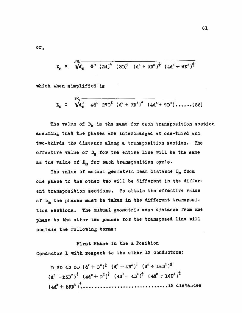
61
or.
D ::zB
hich hen simplified is
18,----------------Da = \7d~ 4d6 2'1D3 {d2 + 9Dz )2. (4d2.+ 9D2 )1•••••• (56)
The value of D. is th same for each tran position s ct10n
assuming that the phases are 1nterchang'ed at one-third and
two~third. the distance along a transposition section. The
effective value of D. tor the entire l1ne will be the same
as the value of DB for e ch transposition cycle.
The alue of mutual geometric mean distance ~ fro
OD . phase to the other two will different in the differ-
ent tran position eet1ons. !o obta1n the tfeet1ve Talue
of Dm ~h. phase mn t be taken in the different transpo81~
tiou aection. The mutQal geometric mean distance from one
phase to the other two pha e for the transpo ad line wIll
conta1u. th. following terms:
ira' Pha '. in the A Po 1~loa
Conductor 1 ,1 h re ct to the oth r 12 conductor.:
I ~ ~
D 2D 4D liD (42. + D~)'I ( Z + 4D2 )2. {d2. + 1.6D~)2.1.' ' , . .L
(dZ+215D2.}2 (442 + D2 )2 (4d2 + 4Dz )"z (4~+ 16»2)2..L .
(40: + 2 »2 )~ ••••••••••.•••••••••••••••••••• 12 d1stancr8S

Conductor 2:
62
~ Z 2-
D 2D 4D oD (d2t + D2.)2 (d'- + 4D~)i: (d~+ 16:02 )"2
z a ~(d +25D }~ ••••••••••••••••••••••••••••••12 d1etances
Conductor 3:
The 8 me terms as Conductor 1 above •••••• 12 distances
Conductor 4:
". ;. f(4d + 4D ) ••••••••••••••••••'•••••••••••••12 d1atance
Cond.u:ctor 5:
~ ~ ~
D' : 2. (2D), ( d2. + D,'~).t (, d2 + 4D2) t, 12 di t• • • • • • • • • •• ' s, ano••
Contuotor 6:
The same trma .a Conductor 4 above ••••••12 distances
~1r8t Phase in the BPosit1on
Conductor 1:
Conductor 2:
Co.uetor ~t
,h .'t __ •• Con4uctor 1 bOT•••••••12 distanoes

63
Conductor 4:
The same terms as Conductor 1 &bove ••••••12 distances
Conductor 6:
!he same te~s as Conductor 2 above ••••••12 distances
Conductor 6:
The same terms a Conductor 1 above •••••• 12 distances
Firat phase in the C position w1l1 give the same terma as
the first phase in the A position but in a different or4er.
The mutual geometric mean distance Dm w111 be the 216th root
of the product of the 216 distance•• or
and simplifying,
D =m~(DI5 ( 2Dt~ (4D)6 (5D)3 (d2 + D';l,)10 (dt.+ 4De
)8
«(2 + 16D2 )4 {d?' + 25D~t (4d2+ D
z )5 (44,2 +4DIt t
(~+ 16D2.)'?' (4 1 + 25D2.>] (5'1)
!h 1ncluoi n for hi. rrang nt can be e lculat d from
th follo 1ag tt10 I

64
Another possible arrangement of the phases is to ~ve
the conductor of each phase alWays separated from one another
by diagonal distance; thus the first phase might comprise
the top conductor of. the first and fourth columns, the middle
conductors of the second and fifth columns, and th bottom
conductors of the third and sixth columns. The oth r t 0
.phases will be arranged similarly. (See Figure 150.)
Aed
BOd
CO
DODO
• 0
o •
•o
o
o
•o
o
o
•Figure 150. Six-Circuit, Three~Pha e Line
(Phase 1 shown in so11d)
1th thla rrangement, transposition is again neCe88&~, and
1th thi taken caze of th equation tor the self geom trio
.ean di.tance of e' ch pha e contains the following terms:
Conductor 1:
, .-L 2. 2. i:t (4,2+ D2 )2 (442 + 4D
2)2 3D (d + 16D )
2 2 i 6 dl tance(44 + 25D) ••••••••••••••••••• ~ ••••••••
Conductor 2:
d
Oon4.uct'or 3:

65
Conductor 4:
to C • I
de (3D) (4 + 4Dz )2 (4d 2 + D2.)~ (42 + DIl:)""£
t. 2 i{4d +4D ) ••••••••••••••••••••••••••••••• 6 distances
Conduotor 5:
!he same terms as Conductor 2 aboT •••••• 6 41 tanc
Conductor 6:
The a,me terms a8 Conductor 1 above •••••• 6 dl tance8
~h. mutual g80m tr1c mean d1 tanc Dm takl'ng tran po 1~
tion Intoaocount 18 found by tak1ng th 216th root of the
following 216 t,rm :
1'1r:t Pha. 8 Shown in F1811r 150.
Conductor 1 wI h reap ct to the other 12 conductor :

66
Conductor 2 with respeot to the other 12 conductors:
4D
Conduotor 3:
••••••••••••••••••••••••••• 12 distances·
(d~+4Dt)I (2D)t Dt. (4dt.+ D~fi d 2d (dt +Dt.}1:
to t1: .. t .2f % ~t(4d + 4D) (4d + 9D) (d + 9D) •••••• 12 distances
Conductor 4:
The same terms as Conductor 3 above ••••••12 distances
Conductor 5:
The ame terms a Conductor 2 above ••••••12 distances
Conductor 6:
Th same t rms a Conductor 1 aboY8 ••••••12 dl tance
Phas On "11 po. d ill Phase 0 Position
Conductor 1:
· · t A42. D (cl~+ D2,)-z 2D (d~ + 4D2.)%. (d2.+ 9D ):l, 4D
t z.. 2. i .(d~ +16D2
) 2" 5D( d + 25D) 12 distanoes
Conductor 2:

67
Conductor 3:
~ 2. ~ 2,..L~..! ..LD ( 2D) (44 + 4D ) 2. ( d Z + D )~ d 2d (d2. + 4Dot ) ~
(4d2 + D
2)"l (d% + 9D
2)t (4da + 9DZ )"i ••••••• 12 distances
Conductor 4:
•••••••• 12 distanoes
Conductor 5:
The same terms as Conductor 2 above ••••••12 distances
Conductor 6:
%. t l I
D 2D 4D 5D d 2d (a.. + D~) t ( 4dz+ 4D~) ~ (d~+ 9D~ ) "£( I I
(44f,+ 9D~ )i: (d 2. + 16Dt.. }"i ( 4dl. + 25D~)"E ••••,12 d1, tano s
Phas 1 transposed in phase 3 position 111 g1 e th same
41atanc as in the above case with phase 1 in phase 2 poa1~
t1on. !h refore, for this arrangement Dm I.
el6t ~o 16 20 1, 6 ZQDm = "td24 D (2d) (ED) (4D) (5D) {d
L+D
2)---z-
{dz+ 4D~)Jt (d2. +9D?')¥ (d%. +16Dt.) I~ (dt. + 25D~)410 '0 ,2, 2-
(4d~+Dz)z; (442.+ 4 })&)7 (4d2.+ 9Dt )2: (~4~+l6D2.)2
(4d~+ 25D~~
hlch Wh n imp11fied is
:n. = 2V"{4Z4 D30 (2d)16 (2D)20(4D)Ii. (5D)6 (dt.+DjIO (d2.+ 4D2)?
12. ~ Z. 5 2- t. 2.. 2, 2. 6(cl£ + 9D~) (d +16D ) (d + 2pD ) (4d + D )
(44~+ 4Df. )5 ( 4dt.+ 9D'L {' (4~ + 16D~" (4cr + 25Dt )1]••••••••••••••• (60)

68
The inductance for this arrangement 1s
L - 10-7 equation f60~ ( )- 2 %. lne equation •59 •• 61
Assuming that d and Dare ea'ch equal to four feet in
Figure 15 and also that the conductors in this arrangement
are all the standard 30 x 7 strand, 556,000 cl~m11t .C.S.R.
conduotor (for which the selt geometric mean ,d1 tal1C8 de
s calculated in equation (3S), eh pter II) the induct nee
w111 be found for comparl on for each of the three phase
rrangements sha 'n in Figures 15 t 15b and 150. Th elf
geometric mean distance de or each 0,1' the conductors 1s
0.394 inches.
Arrangement Shown in :Figure 15a
Yrom equation (53)
D. : 1.790 ~d. D5
=1.'190 (48)~ (0.394)15
=1.700 x 25.1 x 0.856 =38.3 1nche •••••••••• (53&)
Fro quatlon (5&) t and since d equals' D {11&18 4 teet
: 48 x 2.280 =109.4 lnche •••••••••••• '•••••• (54&)
Yro quatlon (55)
, l09.4 h 1L =2 x 10- In. $S.3 enr. per meter-

F 0 u tion 3 hap r , h induct!
6
re at nee drop
at 60 cycle is
=0.2794 0.455 = 0.1271 h per mile p r p ase
• • • • • • • • • • • • • • • • • • • • 55 )
t e pacin nd cond ctor the same a ov J t e
inductanc 'a d re at nee d op for t e arran ment 0 ha
s sho' n in Figur 15b i calc lated as follo 8:
13
= 25.1 x 0.856 1.932 =41.5 lnche ••••••••• (5&)
ro quat10n (56) 1th d = .. 4 t t. From ,quation (57),
8 2. 91 = 105.0 lnchea •••••••••••••••••• {57a)
The inductive e ct nee at 60 cycle 1
=0.2794 x 10 D ~ 0 2794 x log 105.0o 10 -,r:- , • 10 41.5s
0.2794 0.403 =0.1086 ohms per mile per phase
•••••••••••••••••••• (58)
fh 1,duotanc nd r ctanc drop for th phase rrange-
n ho in Figure 150 is c lculat d s follo s:

70
From equation (57)
25.1 0.856 2.139 = 5.8 Inahe •••••••• (59 )
Th mutu 1 geom tric m an diatnce from ,qu tion (6W 1s
= 48 2.0717 =99.73 1nches••••••••••••••••• (60a)
The 60 cycle induct nee re ctance drop in this a e 1
X60, =0.2794 log' 99.73, 10 45.8
~ 0.2794 x 0.337 =0.0942 ohms p r mile per p
••••••••••••••••••••••• (61
ObViOUS~t th be t rrang ment of phases 1s the one
sho 'n in Figure 150; th next best of the thr e arrang m nts
in Flgur 15b. inc th react nee is
pprox1mat.~ 26 and 14 rent 10 r in th bOTe cae
r .p ct1v lY, than in th f1rst • Thi 1 a
1 '0 th d1 t no b t n conduo or of hp
1 r ,cl .1n ih rr m n of 1,gu 15b c m r t

71
Figure 15&; and this is also true for the arrangement of
Figure 15c as compared to Figure 15b. !he mutual geometric•mean distance decreased from Figure 15a to F~re 150 respective-
ly. Therefore, as has been .previously .tat ,d, the b at
arrangement is obtained by placing the oonductors o~ one
phase tar p rt a practicable and the distanoes b tween
conductors of one phase With respect to nother &8 clo e 8S
practicable, keeping in mind the exp nse as oompared to the
dvantages obta1ned by the aboT••

72
S---~~y
thoro' gh stu~ has been made in this thesis of the
pp11cation of geometric mean distances to inductance cal-
culations.
The classic induction formula t based upon the "rationa
lized" .1 .IC.S. system of units is,
DL =2 x 10- 7 lne~ henries per meter
B
where ~ is the mutual geometric mean distance of one· phase
to the ·remaining phases and De is the self geometric mean
distance between conductors of a phase. This formula s
derived in Chapter It starting vith the fundamental equation
of induoed voltage, equation (l), and carrying it on through
to its final form. It was derived from the definition of
inductance and from a consideration of internal and external
flux linkages of a~ cond ctor carrying a current. The
formula is based upon the assumption of uniform current den
sity (or non-uniformity was taken into account by the self
geometric mean distance de of the individual conductor as in
the case of .C.S.R.). This formula, in its present form,
applies to non-magnetic conductors, and A.O.S.R. and copper-
eld conductors Where aluminum or copper carry practically
11 of the current.
The method ot calculating the self geometric mean distance
ds of t dard conduotors was shan in Chapter III, and is

73
based upon some ell established theorems1/.
The application of the basic inductance formula to the
calculation of inductance on multicircult linea as shown in
chapter III. Here, the method of caloulating the mutual
geometric mean distance Dm of one phase with respect to the
other phases was developed, along With methods of ca.lcula
ting the self geometric mean distance of the entire phase.
Dm and Ds were caleulated for several different ar
rangements of the conductors making up a phase along ·ith
different transposition cycles.
This thesiagives the complete method of calculating
the inductance of different types of lines composed of
different conductors by means of geometric mean distances.
lIse. the appendix of this thesis.

74
APPENDIX
·MATHEMATICA LGMD
(
PROO FS oF' T H RE E'THEOREMS
8AS\C
If +~~e'e ferMI ?>re Ct\ ~ ~ eO\'ne1-V"\c.. f'r"§re~, /".,
+he MI6A\-e +('rM (~ g~fcl +0 be +he 8 e,,",,-+rtc. rYIea""()~ +he c+hEtr two ahd @'1l.4al +" +he ~,\C.\.ar~ ..-",,+ oftheiV" )?~odt44:.+) -to.,. i~ 8 1 ~I ahcl" are i.,~eo".,e+rjc...
':>t"'O~\'"e~Sl';l'1 +\,eV\
"k~ ~eome+rlc.. Yhean tne~ '8\'0 IaQexp"nential of +he ~\le~t'~e L'>f +he',no 42
Ins + thee 2 : ~
~o*,,'l#dQ--e6 +~e
\ ,,~a\- '. +.H'~ .J 0 r
p
Wh\~~ ~I\J~, +\\e ~eOVYIe+~\e ""e~~ of '0 -tu"'n<ltt"Dt'\ af
+\-. e ex t'0ne~t,~1 0+ +he ave.r a,:e 01- 4~ e lo~ a r i +h"!" of'+he ~~\-\4;',~., •
For e)(a~p\e, oon9\~er' 0 o,·t'-C \e o-t r~~l~' V;
'On6 ~ l'0i,,+ J ?, whose&\~+a"<!e t"O~ ;'\'e ~@h~er.
0/ '~ b (acg. show'" th F\8 ~r-e a).S~ -the \'aw of CO~·\h~S) +h~
d\S1- ~",~e -from f'Oih+ P +0
+he ~xt~e~\,.'1 of r r~d\·us,
do. 1 ~~W\ rt§ d Y\ ~ h'1 \e a

75
d = V'('"l.. + 10 1. - 2 r 10 co s e
Tah'I~~ +hls o~ '2l +~~C -\-\()l-l of -t-ht' arc. \e'h~ +h 0\"\
+~ec.\'t'e\eJ and ~'P"\'1ih~ t-he geOMQtria \"f\e~h, ~s
lu..~~ det'I~~dJ Clver the whole c.\r~ \e J 0 w'\l became theSI@O'mQ-tt-'IC. rneah d.\~+a\'\Qe J D J ott-on, 1'0""'+ P +0 ~he
cHr~u.\"n-te\"~nce. ~lti4L +he Z'>vev-a: e {~ u~~ha~:eJ h~
a ~h~h:e \h ~~~le I 11- ea.h be 4ake" wi+~ r~,~ee"- ""-09 J ~hd SI~C! e \+ ,'$ ~" elJ"h +~'n(!+IOhJ the ~vet'" ~~e
h1~,\ be +a.\(e\1 +r()~ 0 ~Q '1\. Th~sJ
l \i , 0 = .;f rIV1 (r1.:+ b "" - 2 r 10 Co, e) cl ~ •
o :
i his : :,i·nte~ .. a\ is a ~o,,+ I'on L4olAol .f'-l.~(!,,",IDh ~f yo -for
aH val""es J +~e.'r~ ~()'('e ~\.f.(~renfi$t;~3 \Ni+~ resf'~C'+ +0 r J
wh,'a.\' w',\l h"ld eXdep" IN'hel''l re.,L\.~~S b J thE.e" ~.~~ '·0 ~ b~co ~, , I
d th 0c1r
\-: --
1f
11
1 Zr - ~ b ~os e-- .. de~ ""4-\o~- a,r·~cos8
=,
---1i
~4~it\~ 3hJ 1t.t.\'+ra~+lh~ b"2. J
r1..~r-'" -Zr b ~a~~ 4- \0"'-\4'2rC¥'-.;.\o"". ~~\S C~!9)
\')'\l.A.1+lpl'1jh~ 0; i; dt\d
r - b "0 S ~ ~---_.......--------- )( ~ :r\..+1::r&. - ~ ... '" eos ;; ~ r-
r~d~ ~t n: I
Y'\._~", b "o~ s + b'Z~ (v'2..4-\o'---~v-\o~O\e,)

76
,~ -
7f
\l'.earr~hgH'lg ~he d8116~jnat~r of -\--he I~~+ +-~Y\'h SO
',\- c~~ be \'nore recc\'tI~ .i-rt1!~8\"'&-{~J ~h~ apt't'11'lt~
4-r,~o»,e -tric. I'd @",,-t-it'jl CO$~X -4- St"l12. X J:' \ } and <:!O$ x::Co~'1. t - SI'\1'" ~ I i+ b~('omes
r-%.+b1.- - Z~'" (!6'~ "I: (r\.+~'-) ~\·h~~ -f- cos1.~-2. 2.
Zr~ (cos~: - 'l·h1,.~J
::: , ....0+\3)'1. S,'h 1.~ -1- (r~k:s)l.. ~o~t.i
NOI4J h.."dt I 'pl.fitl"l ~h d "IV j J ,," ~ "'1 (loS 1- tf(r+b)~ ,lh2.~ + (r-b)"a.:)s2.4!-l Co£1.s 1:
C "" 4j cos"S
[tr '4- ~),., +ah 2 e .... 'r-~\"J Cos I. S
S,n" ~ ~ @c't. e ~ +h.e .(="~ "'" a+I'"", b~con1C'S.. ---If/Io
(105"8
11,..1- - b'- l ,
de---- ::
z~ rr r ~+ b'- - 2. ,. b Co s a
I--11
7fsee 2.6 J ~
'Y-4-b)1. tah"8 + (r-b)1.
:=---

Wh"~h \9 how of the f f cJ~ Jar~ +~V\
L(..
otw\ t.4,1..-ra' ~ -- -a a+he.~e foy- e I
'Iir ~ - b~ I I- de -fy- r" ..... b1.- Z r b -rr Co5 S
'17
r'--\o'- I 2-~~ rr {r+~)("-b\
,--1i
t=-
tr
Thttre fot~ the +(n.e\ e'l4.at ("h becoh't ~ s
d In D I <9 ] 1T" I \""'-~'"d~ ,;: 1i 2r- () .... ~ TrL. -b'"l
St'Aee \r\.- b~\ i~ b~ abto\u.+e. Vblu.e ~~~ wi\1 ~\w~'1s
be p()~·\+iuc. J +\,eref-o ...e whe~ .... it ~\"'2at~.. +han k:t
d \h D I , 1:: ---- -4- - -= ...."
dr- 2r Zr r
8\10 when r \~ \e, s +h~h \0
0 tn D t \.. --- -- :. o.d~ 2r- 2,~

78
:: In b ~
Theref'o __e whet1 r =0 J 0: "'. If r i" 8 re~+er th ~~ bJ
frDn-, +he 8bo\l~ e9~~4to\1
d th D
drd , t\ 0
Ta\(ih~ +\,e .\;,,+eg r a\ 0+ bD+-h Jld~s +h~ 4!!1'4.8+ I O"bec-o~ .,
+n~ ~~ .f,r'teV' \~ I \ e s )'
o ~ ~ wh~~
+-\, a~ b
" In 1:) ~ 0
•, . l~ 0 = C I
b1.4+ "" 'n Q.y,
va\~A!' fJ+
...
l" ~.:) . \n 0:: \h b whl'~~ Yhu.s+ ho\ci fOl" ~\l
b J +her~~"re when r (~ letS +h~\1 b,
c ~ lh bIn 0 ~ \ h b
D:\'

79
Th~se res~)+s aV"e C0Y1'LS+8ht wi+,h +hi' ~a~+ +he++he (t'I+,"~ral (s S'!t)1\11et r ,c"t ih rand b.
1 h '" S J +'" e ~ Y), 4 .f NI """ a p" ,on+ +0 ~
di't'Cu.Y\'\-li!V"e't\Q4!. is @'l",,~t +0 ',+s d\f-t~hct~ +...~"" +-\,~
aehteV" ,T\, .. o\'"~"", lIr, (!.h~¥,+eV" Ir) "'hOi! i+- ~as prj)l1E'd
+ha+ w\'~V\ \0> ~ ) D~ "'~
When \:,~'r I D:: r, Tnt'S' P"""&J~S The"r2""'II LC.h~\,,-\-A!\":It) \.M\,"(lh '+4l-\-~s 4---h~+ +h.e d tnd -fro.....,a (H r e "'" \~ ~ \ \~ e of r b 4 ,<.4. \ ~ +0 b h " ¥' 0 I h +- J I.), ~ 7
(3V" aye~ in +I,e ~&~Q p\et\Q &~d l.4I\"oU~ ~~closed
):,'1 +\,~ Q\V-Q~\~~ \,'h~ \., e''l''-21 +0 ,+, ~~J,i.4.J~
THE SEl.F laMD of A C\RCUL.AR A REA
, "'e GMD t v-() n, a\1 ar~ 0 t· S <ieflhed 10'1
\\1 o -: ;: *, t;;. I\') .sAA' dA dA'
G,u~\1 ~ (!, r<:L lc.. 0'; raA ,4~ aJ +0 T'l1d i+s 'f'I'; QMO
&1. = ~~ --+ r~ - 2 ret r). ~oS 6
(J,.aw CIt CO~Il1~S)
~ • I ,t ~ lJn· a -: 2. h r- ~ + r1. - Z t-, r.... ~~s e
A,:A t -::rra2.
g'l1(!~ t-he d\·~-\-o.hoe
-t'V-OkY\ f', -t" P2.~'1 (A ~, S
+\,e ~\~t a~"e +rDh,
P~ +0 P, over the c,'r(!le.t\-,e \o~ 01- +he GI'1 D

80
+0 P2 1>, w4"\1 ~S +he \eh~ +h ~t"0t\1 P2,. +0 ~ •9n~4" 4-hQ in+eat"b l f'O"thlnO\~42S +~.·S d,'s+-~"(lPo~d'1 ()h~t21 +he {.o+al expr~S'rl~'" l"h"-I.f. beh'\ C4' +- t \0' I (::t A b '1 ~,
dA - ~ dr, dB
+\,.e~ ~ fore
2tn 0 -:
TI J. a+
tYtCr,,1.-+r~ - ~r,r-i. CDIS) de4t1
r. d., . va'\.. cL ~~.
7T
"Ii
J...,-,+ r = I'., (V'~ .......~- 2~ ...~a,,'.)de
rr4 I
---

81
-- 4-
••• a -\3 cose 1- ~1.
a - '" ----I+Z.~

When r. :: 0 I ~ 2 TT In ~a, + c
I : f: r ~ d e = 2 11" I h ra
82
Ih 0 1:
4=
t'1.ZIT
e l,J h ""2" r. d r-, t"" JY",
'h r,,- r, dr; r",- dr'-
••• I" 0

\n D = ~[~4'ha_ 34
]a4 4 16
Iin a -4-
83
~,2,5= In a - It-\e

84
BIBLIOGRAPHY
1. A.O.S.R. Eleetr1eal characteristic (pamphlet).Aluminum Comp ny of America, Pittsburgh, Pa.
2. Copperw ld eng1neer1ng data (pamphlet). CoppereldSteel Company, Gla aport, Pa.
3. De eese, F. C. Transmission line t design constructionand p rformance. Ne York, McGra -Hill t (1945}. pp.16-34.
4. Dwight, H. B. Geometric mean distance for rectangularconductors. Electrical Engineering. Vol. 65. pp.536-538 (1S)46).
5. Dwight, H. B. Skin e=tt,c, and proximity effect in tubular conduator. A.I.E.E. Trans., Vol. 41, pp. 189-198(1922) •
6. Franklin, P. Difter 11 1al quatlon8 tor eleotrlC8,lengineers. 5th printing. N. Y•• 11ey,(1946). pp.51..53.
7. Grover. F. • Inductance calculation. N. Y. t VanNostrand (1946). pp. 17~25.
8. Gro er, F. .t and Rosa, E. B. Formulas and tabletor c lculat10n ot mutua.l and seltinduotanc8s. u. S.Bureau of Stand rda, So1ent1~lc paper 8169, Vol. 8(1912), pp. 166~170.
9. Guy., C. E. Comptu8 Rendus. Paris. Vol. 118 (1894),pp. 1329.
10. Maxwell, J. C. Electrlaity and magnetism. Vol. II,2 .. ed. Oxford. Engl, Carendon Press (1881). pp. 298-302.
Electrical charPittsburgh, Fa.,
Nesbit, -., and est1nghouse Engineers.acteristics of transmission clrc'ulta.D rd ed., (1926) pp. 1 - 9.
12. Royal Sooiety of Edinburgh Trans. Vol. 26 (1878), PP.1176-80.
11.
13. ! rboux. J. G. Introduction to electric power systems.Scranton, Pa., International (1944), pp. 16-34.
14. U. S. Bureau of Standards. Scientific papers. Vol. 4,(1907~08), pp. 325~236.

85
15. "est1nghouse Electric Co. Electrical transmission anddistribution reference book. ~rd ed., Pittsburgh, Pa.,(1944) pp. 29-40.
16. j'oodru.ff, L. F. ·~lectrlc poer transmission. 2nd ad.N. Y., 1Viley (1938), pp. 13-51.
17. ,~'Voodruff, L. ~.,. Inductance of aluminum cable-steelreinforced. .I••E. Trans. Vol. 54, pp. 296-300(1935) •