study of the crack extension about splitting grouting ...journal.it.cas.cz/61(2016)-4b/24...
TRANSCRIPT

Acta Technica 61, No. 4B/2016, 249–260 c© 2017 Institute of Thermomechanics CAS, v.v.i.
Study of the crack extension aboutsplitting grouting based on fracture
mechanics1
Teng Wang2,3, Mingru Zhou2,3, Yanmei Ding4,Guowen Lu2,3, Guangkang Zhou2,3
Abstract. The extended geometric shape of soil crack is an important factor in the strength-ening design of split grouting, but the occurrence and development of soil split grouting is difficultto be visualized. This paper studies the cracks form of splitting grouting, establishment of thefailure criterion and determination method of crack from the point of fracture mechanics. In orderto establish the finite element model of crack extension we employed ABAQUS software togetherwith engineering parameters of soil reinforcement from Lanzhou New Area fast road project K1 +662.053. We also analyzed the crack length and effect of split grouting pressure and the impact ofsoil physical and mechanical properties. This research report demonstrates that when calculatingsplit grouting pressure we should take the impact of crack extension length and soil strength pa-rameters into major consideration. Crack length is affected dramatically by grouting pressure inwhich it shrinks non-linearly as the crack length increases.
Key words. Loess, split grouting, crack length, fracture mechanics, extension (propagation)behavior, effective paths.
1. Introduction
Grouting technology is a very professional academic branch of geotechnical engi-neering which has a good effect in improving the engineering geological conditions.Fracturing grouting is the exploitation of slurry pressure to promote the expansionof soil cracks, which changes the original structure of soil. And through the filling ofthe slurry it should also eliminate the soil of the overhead space, eliminate the col-lapsibility of soil, and, finally, to achieve the purpose of reinforcement [1]–[3]. Due to
1This work was carried out in the frame of Science and technology project of Gansu Province(JK2014-34).
2Western Engineering Research Center of Disaster Mitigation in Civil Engineering of Ministryof Education, Lanzhou University of Technology, Lanzhou, 730050, China
3Lanzhou University of Technology, Lanzhou 730050, China4Architectural and Civil Engineering Institute, Weifang University of Science and Technology,
Weifang 262700, China
http://journal.it.cas.cz

250 TENG WANG, MINGRU ZHOU, YANMEI DING, GUOWEN LU, GUANGKANG ZHOU
the conspicuous soil thickness in the Loess Plateau region, utilizing grouting methodto reinforce the building of settlements has become an effective mean of technology.However, most of the engineering design is blindness, and the selection of groutingparameters often depends on subjective experience. In addition, the research onthe expansion behavior theory of the slurry in the soil body is very slow during thegrouting.
It is very necessary to study the fracturing grouting crack propagation distance,which has a close connection with the effect of grouting reinforcement. The hy-draulic fracturing process usually refers to the soil or rock mass that they producecrevice under high liquid pressure [4]. This theory is not only the theoretical basisof treatment engineering seepage control, but it is also the key method to solve theunderground grouting engineering. The stress intensity factor is an important pa-rameter to characterize the fracture of material, and it is one of the most importantfactors for solving various kinds of cracks of fracture mechanics [5]. In order todevelop a calculation method for the fractured rock mass fracturing grouting pres-sure, Zou et al. adapted a strength criterion of nonlinear Hoek-Brown in fracturemechanics, and established the type II and mixed mode cracks of fracturing grout-ing pressure calculation method in the fractured rock mass, which introduces thehydraulic fracturing theory and fracture mechanics method into the theory of frac-turing grouting [4]. Aiming at the plane strain of tunnel, plane model study of elasticstage of composite soil after split grouting was studied; on the basis of the study ofthe existing split diffusion model and area equivalent principle, a two dimensionalsimplified equivalent unit model of the composite soil after split grouting was putforward. Based on the theory of homogenization, the equivalent elastic parametersof the two dimensional simplified model were derived by the principle of deforma-tion coordination [3]. Based on the Bingham constitutive model, a single plate crackslurry transport equation was established under the condition of constant pressuregrouting [10]. However, most of studies were based on special rock conditions, andit was difficult to better explain the strengthening mechanism of split grouting incollapsible loess area of large thickness.
To research the criterion and determination method, a finite element model ofcrack extension was established by using ABAQUS software and combining LanzhouNew Area fast road project K1 + 662.053 engineering parameters of soil reinforce-ment. Some aspects of soil were also analyzed, such as the crack length, effect ofsplit grouting pressure, and impact of physical and mechanical properties. It pro-vides guidance and references for the engineering practice of split grouting in thelarge thickness of the west of China.
2. Fracturing mechanics analysis of fracturing pressure
2.1. Griffith crack assumption
The substance of fracturing grouting is to use high pressure grouting process,based on injecting cement or chemical agent. Then the grout puts additional com-pressive stress to the surrounding soil and the soil produces shear fracture and frac-

STUDY OF THE CRACK EXTENSION 251
ture failure. According to the theory of Griffith crack [5], fracture is not the twopart along the interface of crystal breaking, but the result of the soil mass crackextension under the pressure grout in the process of grouting soil.
In this paper, the substance of the loess in the process of fracturing groutingcracks under the uniform internal pressure was simplified for the elliptical hole pro-cess Griffith crack under the uniform internal pressure. As shown in Fig. 1, weassume that the soil in the distance is not subjected to force, and affects the dis-tributed pressure p on the elliptical hole L evenly. Then, according to elastic theory,the boundary conditions are as follows [5]:
Fig. 1. Stress distribution in fracture model
for√x2 + y2 →∞ : σij = 0 . (1)
For (x+ y) ∈ L there holds
σxx cos(n, x) + σxy cos(n, y) = −p cos(n, x) ,σxy cos(n, x) + σyy cos(n, y) = −p cos(n, y) .
}(2)
Here, cos(n, x) and cos(n, y) express any point outward normal direction of di-rection cosine. Symbol n expresses the the unit outward normal to the point.
According to fracture mechanics theory, the hole side stress can be obtained usingthe formula
(σϕϕ)ρ=1 = p 1−3m2+2m cos 2ϕ1+m2−2m cos 2ϕ ,
(σρρ)ρ=1 = −p ,(3)
where m = (a− b)/(a+ b).

252 TENG WANG, MINGRU ZHOU, YANMEI DING, GUOWEN LU, GUANGKANG ZHOU
The maximum normal stress is
σmax = (σϕϕ) ρ = 1ϕ = 0, π
= (σyy) x = ±ay = 0
= p1 + 3m
1−m= p(−1 + 2
a
b)
. (4)
Comparing the formula (3) and (4), the radius of curvature ρ0 → 0 at the topof the elliptic semi-major axis, internal pressure of elliptical hole and stretching ofmaximum normal stress of elliptic hole are almost the same. At the same time, theelliptic hole is transformed into a Griffith crack when b = 0.
2.2. Establishment of fracturing crack failure criteria
Stress distribution within the crack is composed of two parts when fracturinggrouting, namely the original ground stress and pore fluid pressure. As stipulated infracture mechanics, tensile stress is positive and pressure stress is negative, while theplus-minus sign is just contrary in soil mechanics [4]. To simplify the calculation, thispaper considers the compressive stress positive. Then, the soil mass crack fracturemechanics analysis model diagram is shown in Fig. 2. Assuming that the soil ishomogeneous and isotropic, according to the linear elastic theory of semi-infinitemedium, the shear failure criterion satisfies Mohr–Coulomb criterion.
Fig. 2. Soil mass crack fracture mechanics analysis model diagram
The criterion expression is
τ = C + σn tanϕ , (5)

STUDY OF THE CRACK EXTENSION 253
τ =σ1 − σ3
2sin 2α , (6)
σn =σ1 + σ3
2+σ1 − σ3
2cos 2α . (7)
The symbols τ and σn represent the shear stress and normal stress on the surfaceof the shear failure, respectively; symbol α shows the shear failure plane method andthe maximum principal stress direction angle, ϕ and C show the internal frictionangle and cohesive force of soil, respectively.
According to the principle of Terzaghi effective stress, the pore pressure of soilshear failure occurs and can be expressed as
p1 =σ1 + σ3
2+σ1 − σ3
2cos 2σ −
(σ1−σ3
2 sin 2α)
tanϕ. (8)
In accordance with the above analysis, the serous fracturing surface usually occursin the stress on the surface of least resistance. So we can see that once the normalstress on the surface of the shear fracture is equal to zero, cracks begin to expand,and the pore pressure is
p2 =σ1 + σ3
2+σ1 − σ3
2cos 2σ . (9)
2.3. Fracturing grouting discriminant methods of crack ex-tension
When fracturing grouting loess conforms to the rule of fracture mechanics of thepropagation of the crack (namely during crack propagation), the end of each pointstress intensity factor is equal to the critical stress intensity factor of the loess [5].Fracture criterion of crack propagation is then as follows
KI = KIC . (10)
The symbol KI is the crack extension criterion which is the stress intensity factorof crack, while KIC is the fracture toughness. Among them:
KI =p√π
E(k)
(b
a
) 12
(a2 sin2 ϕ+ b2 cos2 ϕ)14 . (11)
The formula E(k) is the second type of complete elliptic integrals, namely
E(k) =
∫ π2
0
(1− k2 sin2 α
) 12 dα , (12)
where
k2 =a2 − b2
a2. (13)

254 TENG WANG, MINGRU ZHOU, YANMEI DING, GUOWEN LU, GUANGKANG ZHOU
The length and width of the crack are equal when assuming that the crack frontis infinitely small, namely a = b. The elliptical crack becomes a disc crack at thistime and
E(k) =π
2. (14)
Then a simplified formula can be obtained and at any point the stress intensityfactor of homogeneous internal pressure along the elliptic crack front is
KI =2p√a√π
. (15)
3. Model analysis
3.1. Project summary
The fast road project K1 + 662.053 is a section of engineering in Lanzhou newdistrict, Formations for the top are loess, gravel layer and the bedrock. Accordingto the field condition, the design of grouting depth is 5.m, the undisturbed loessunder SEM microscopic structure is as shown in Fig. 3, undisturbed loess mechanicsperformances are shown in Table 1.
Table 1. Mechanical properties of intact loess
The mois-ture contentω (%)
Void ratio e Modulus ofelasticity E(GPa)
Poissonratio µ
Cohesiveforce C(kPa)
Angle of in-ternal fric-tion ϕ (◦)
20.3 1.10 20 0.3 32 26
Fig. 3. Microstructure of undisturbed loess SEM: left–100 times magnified,right–500 times magnified

STUDY OF THE CRACK EXTENSION 255
3.2. Model building
The grouting process of crack propagation was simulated by the finite elementsoftware ABAQUS. The stress intensity factor of the calculation unit can be cal-culated by the analysis of the stress and serous pore pressure values of the model,and whether the crack will extend can be evaluated by the criteria proposed in thispaper. The model area is shown in Fig. 4.
Fig. 4. Crack growth demonstration model
The parameters were selected in the following way: the fracture toughness ofthe loess is taken KIC = 2.7MN/m3/2 and the fracture energy in the shear mode is54.7 J. Cohesive unit selection is COH2D4, other materials selection is CPS4R, thefield test process can be determined using this method of the stability of the loesssoil structure by analysis the calculation results. The analysis of fracture-initiationpressure and fracture morphology belongs one of the key technologies of fracturegrouting. According to the changes of stress path in different times, the damage ofthe element can be analyzed, and the crack propagation in different periods can beobtained. The element boundary taken as a "Path" is shown in Fig. 5, the calculationpath being conducted from the bottom up.
3.3. Data analysis
According to the changes of stress path in different times, the damage of theelement can be analyzed, and the crack propagation in different periods can beobtained [11–12]. The calculation results of stress path are shown in Fig. 6.
In Fig. 6, we can see that the maximum value of S11 at the lowest end of thepath is less than 2.7MPa when time t = 0.075 s, and the interface did not appearfailure behavior. The S11 at the lowest end of the path achieved the damage valueof 2.7MPa when time t = 0.1143 s ,and the lower end of the unit began started todamage at this time. When time t = 0.1720 s, the path at the bottom of the interfaceis declining S11 value of damaging the original point. The value is not zero, whichindicates that the damage value D does not reach 1 yet, although destruction was

256 TENG WANG, MINGRU ZHOU, YANMEI DING, GUOWEN LU, GUANGKANG ZHOU
Fig. 5. Calculated interface path diagram
Fig. 6. Path diagram of calculation results
conducted here. The interface crack tip continues to spread along the path. Whentime t = 0.2585 s, one can see several S11 values on the top of the patch and bottomis zero. It is showed that the damage value of these units has reached 1, and itmeans a complete failure state. When time t = 0.3882 s, the failure units continuesto increase, and crack continues to propagate along the path.

STUDY OF THE CRACK EXTENSION 257
By analyzing the pressure of different periods, it is found that the damage of theunit is advancing slowly with time and the failure unit is increasing slowly. At thesame time, the expansion of the crack also expands slowly with the increase of thefailure unit, which shows that the stress intensity factor of the crack is greater thanthe stress intensity factor of the unit. With the expansion of the crack, the stressintensity of the crack gradually becomes smaller and smaller until it is less than thestress intensity factor of the element.
Cracks of soils are expanded through grout pressure in fracturing grouting tochange the original structure of the soils. Overhead inter-spaces of the soils areremoved through filling grouts, thus removing collapsibility of the soils and reachingconsolidation [9]. The curves of crack length and grouting pressure are as shown inFig. 7.
Fig. 7. Curves of crack length and grouting pressure
One can see in Fig. 7 that the crack length is affected by grouting pressure signif-icantly; with the crack length increasing, the grouting pressure presents a nonlinearincrease curve. At the same time, the nonlinear extension of the crack length in-dicates that the structural integrity of the local loess is better; the reason is thatonly the integral loess soil can form a long crack length. On the contrary, if thecrack length changes not obviously with the increase of grouting pressure, it meansthat the structure integrity of the loess is not completed and may be damaged. Inaddition, the tension stress and shear stress that the slurry in the extension processin soil needs to overcome, increases with the increase of the crack length. Therefore,from Fig. 8 we can see that grouting pressure increases with the increase of the cracklength.

258 TENG WANG, MINGRU ZHOU, YANMEI DING, GUOWEN LU, GUANGKANG ZHOU
Fracturing grouting cracks extension is not only related to the grouting construc-tion technology, but also to the in situ stress and physical and mechanical propertiesof soil [6]. As one of two important parameters of the rock (soil) mass, internal fric-tion angle is a shear strength index and an essential parameter of engineering design[7]. Internal friction angle of the soil reflects the frictional characteristics. Influenceof internal friction angle of the soil on grouts flowing in the cracks is remarkableduring fracture grouting.
Fig. 8. Relationship between grouting pressure and internal friction angle
Based on literature [13], shear strengths of rock and soil material consist of twoparts. However, the cohesion reaches its peak when in small deformation, whilethe friction can only give full play upon occurring rather large deformation. As aresult, the cohesion displays fragility of the rock and soil, while the internal frictiondemonstrates plastic property. A curve of grouting pressure changing along withthe variation of the internal friction angle is shown in Fig. 8. We can see from Fig.that gradually increasing grouting pressure is required with the increasing internalfriction angle of the soil. As the destructive process of the rock and soil is just theprocess of the friction gradually play its role, the larger the internal friction angleof the soil; Grouting pressure shall overcome the strength of the soil, leading to thegreater resistance of flowing grouts. Thus, the greater grouting pressure is required.
3.4. Test analysis
In the process of the actual test, fracturing grouting soil mass crack propagationcan be analyzed by the change of displacement of soil. Because the test zone of
STUDY OF THE CRACK EXTENSION 259
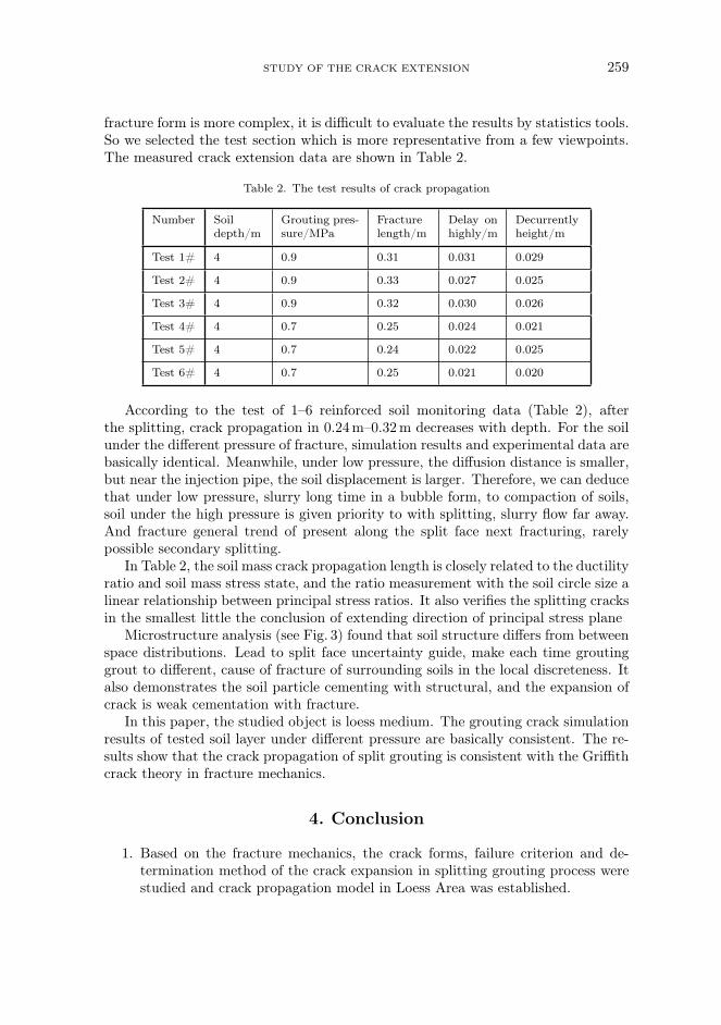
fracture form is more complex, it is difficult to evaluate the results by statistics tools.So we selected the test section which is more representative from a few viewpoints.The measured crack extension data are shown in Table 2.
Table 2. The test results of crack propagation
Number Soildepth/m
Grouting pres-sure/MPa
Fracturelength/m
Delay onhighly/m
Decurrentlyheight/m
Test 1# 4 0.9 0.31 0.031 0.029
Test 2# 4 0.9 0.33 0.027 0.025
Test 3# 4 0.9 0.32 0.030 0.026
Test 4# 4 0.7 0.25 0.024 0.021
Test 5# 4 0.7 0.24 0.022 0.025
Test 6# 4 0.7 0.25 0.021 0.020
According to the test of 1–6 reinforced soil monitoring data (Table 2), afterthe splitting, crack propagation in 0.24m–0.32m decreases with depth. For the soilunder the different pressure of fracture, simulation results and experimental data arebasically identical. Meanwhile, under low pressure, the diffusion distance is smaller,but near the injection pipe, the soil displacement is larger. Therefore, we can deducethat under low pressure, slurry long time in a bubble form, to compaction of soils,soil under the high pressure is given priority to with splitting, slurry flow far away.And fracture general trend of present along the split face next fracturing, rarelypossible secondary splitting.
In Table 2, the soil mass crack propagation length is closely related to the ductilityratio and soil mass stress state, and the ratio measurement with the soil circle size alinear relationship between principal stress ratios. It also verifies the splitting cracksin the smallest little the conclusion of extending direction of principal stress plane
Microstructure analysis (see Fig. 3) found that soil structure differs from betweenspace distributions. Lead to split face uncertainty guide, make each time groutinggrout to different, cause of fracture of surrounding soils in the local discreteness. Italso demonstrates the soil particle cementing with structural, and the expansion ofcrack is weak cementation with fracture.
In this paper, the studied object is loess medium. The grouting crack simulationresults of tested soil layer under different pressure are basically consistent. The re-sults show that the crack propagation of split grouting is consistent with the Griffithcrack theory in fracture mechanics.
4. Conclusion
1. Based on the fracture mechanics, the crack forms, failure criterion and de-termination method of the crack expansion in splitting grouting process werestudied and crack propagation model in Loess Area was established.

260 TENG WANG, MINGRU ZHOU, YANMEI DING, GUOWEN LU, GUANGKANG ZHOU
2. Through the model analysis, it is concluded that the crack growth is controlledby the fracture factor. The stress intensity factor of the computational elementcan be calculated according to the crustal stress and pore pressure, and throughthe decision criterion it is possible to evaluate whether the crack is extended.
3. The crack expansion of split grouting is not only related to the grouting con-struction technology, but also related to the crustal stress and the physical andmechanical properties of soil. The effect of crack length by grouting pressureis particularly significant, also the regularity of crack length illustrates the sta-bility of the soil structure. Using this method can determine the stability ofloess soil structure in the field tests, and provides a theoretical guidance forthe follow-up field reinforcement design.
References
[1] X.Zhang: Study on mechanism of slurry diffusion and sealing at the process of under-ground engineering moving water grouting and its application (Ph.D. Thesis). Shan-dong University, Jinan, China 2011.
[2] A.Bezuijen, R.T.Grotenhuis, A. F.Van Tol, J.W.Bosch, J.K.Haasnoot:Analytical model for fracture grouting in sand. J Geotechnical and GeoenvironmentalEngineering 137 (2011), No. 6, 611–620.
[3] Y.W.Guo, S.H.He, X.M.Guan, X.B. Liu: Theoretical study of plane equivalentelastic model of composite soils with fracturing grouting. Rock and Soil Mechanics A36 (2015), No. 8, 193–201.
[4] J. F. Zou, W.Tong, H. Luo, X. F.Wang: Mechanism of fracture grouting for frac-tured rock based on Hoek-Brown failure criterion. J Central South University (Scienceand Technology) 44 (2013), No. 7, 2889–2896.
[5] T.Y. Fan: Theoretical basis of fracture. Science Press, Beijing, China, 2001.[6] Q. S. Zhang, L. Z. Zhang, R.T. LiuLaboratory experimental study of cement-silicate
slurry diffusion law of crack grouting with dynamic water. Rock and Soil Mechanics(2015), No. 8, 2159–2168.
[7] P.Tu, X.H.Wang: Study on experiment of subsea tunnel grouting materials. J Rail-way Science and Engineering (2010), No. 6, 60–64.
[8] J. F.Kou, F.Xu, J. P.Guo, Q.Xu: Damage laws of cohesive zone model and selec-tion of the parameters. J Mechanical Strength 33 (2011), No. 5, 714–718.
[9] Q.Wang, R. Zhang: Experimental research on the trend of slurry about fracturinggrouting and soil displacement in different pressure. J China Railway Society 33 (2011),No. 12, 107–111.
[10] G.Gustafson, J. Claesson, Å. Fransson: Steering parameters for rock grouting.J Applied Mathematics 2013, paper ID 269594.
[11] F. Sun, D. L. Zhang, T. L.Chen, X. P. Zhang: Meso-mechanical simulation offracture grouting in soil. Chinese Journal of Geotechnical Engineering 32 (2010), No. 3,474–480.
[12] J. Zhou, G. Zhang, G.Kong: Meso-mechanics simulation of seepage with particleflow code. J Hydraulic Engineering 37 (2006), No. 3, 28–32.
[13] Z. J. Shen: Breakage mechanics for geological materials: an ideal brittle-elasto-plasticmodel. Chinese Journal of Geotechnical Engineering 25 (2003), No. 3, 253–257.
Received November 16, 2016