asce conference proceedings paper grouting and jet grouting … · 2019-12-24 · application of...
TRANSCRIPT
Application of grouting and jet grouting techniques – 1 – Rev. 04/2017
ASCE Conference Proceedings Paper
Grouting and Jet Grouting for soil and rock impermeabilization under
extreme conditions at the Diavik Diamond Mine's A21 Project. The point of
view of the Contractor.
Piero Roberti. Author, Civil Eng.D.,1 BAUER Spezialtiefbau GmbH ,
and
Albert Hartmann Dr. Eng. Author, 2 BAUER Spezialtiefbau GmbH
1 Head of Product Group Grouting Bauer - BAUER Spezialtiefbau GmbH, BAUER-Straße 1,
86529 Schrobenhausen, Germany; e-mail: [email protected]
2Head of Product Group High Pressure Grouting - Bauer BAUER Spezialtiefbau GmbH,
BAUER-Straße 1, 86529 Schrobenhausen, Germany; e-mail: [email protected]
ABSTRACT
A new dike will be constructed around the fourth kimberlite pipe, named A21, of the Diavik
Diamond Mine in the Canadian North West Territories. In August 2015 BAUER Foundations
Canada, a subsidiary of BAUER Spezialtiefbau GmbH, based in Schrobenhausen (Germany)
received a major contract with a value of around 65 million euros to create a cut-off wall for the
Diavik diamond mine in Canada.
Jet grouting and permeation grouting with cement based grouts will be carried out to form part of
the water tightening core structure of the dike. This paper describes the permeation grouting
techniques as well as the approach that will be used for the jet grouting for the sealing of the soil
layers underneath the cut-off wall (Bauer CSM) and of the weathered rock zone, down to the
partially fissured bedrock.
Almost 70% of the grouting works have been completed within the end of 2016. The jet grouting
site tests for season one have been completed in October 2016.
Some aspects related to design and methods, the lessons learnt as well as the main challenges the
have been faced within season one of the works (December 2016) are described into this paper.
INTRODUCTION
The A21 diamond-bearing kimberlite pipe is intended for open-cast mining and is located under
the waters of Lac de Gras at water depths of between 5 and 25 m.
Application of grouting and jet grouting techniques – 2 – Rev. 04/2017
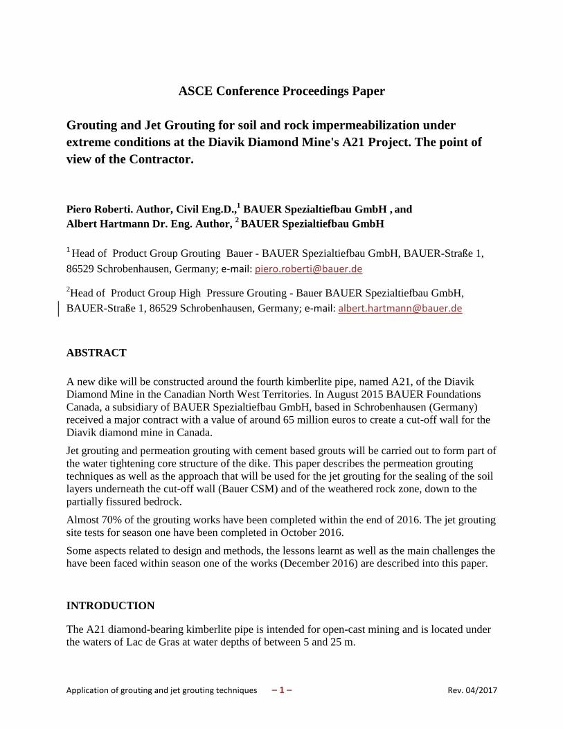
Figure 1. Scheme of the A21 excavation pit with the kimberlite pipe and the dike
The pipe will be open pit mined after the construction of temporary water-retaining dike
encircling the ore bodies using crushed rock fill material. The diked area will be de-watered by
pumping the pools within the dike dry. After dewatering, the till overburden is removed to
expose the Kimberlite pipes for mining. Then conventional open-cast mining can finally begin.
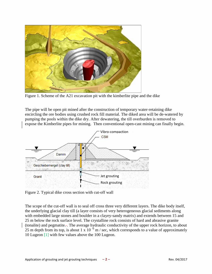
Figure 2. Typical dike cross section with cut-off wall
The scope of the cut-off wall is to seal off cross three very different layers. The dike body itself,
the underlying glacial clay till (a layer consists of very heterogeneous glacial sediments along
with embedded large stones and boulder in a clayey-sandy matrix) and extends between 15 and
25 m below the rock surface level. The crystalline rock consists of hard and abrasive granite
(tonalite) and pegmatite. . The average hydraulic conductivity of the upper rock horizon, to about
25 m depth from its top, is about 1 x 10 -6
m / sec, which corresponds to a value of approximately
10 Lugeon [1] with few values above the 100 Lugeon.
Vibro-compaction
Jet grouting
Rock grouting
Application of grouting and jet grouting techniques – 3 – Rev. 04/2017
The required residual permeability of sealing cutoff wall is 3 Lugeon. The permeability values
and grout takes in the first 400 m of curtain, starting from the north edge are until date, with few
exceptions near to dike foundation, generally low.
Due to the very heterogeneous nature of the different layers to be sealed off, various geotechnical
processes are employed, such as vibro-compaction, pre drilling to the toe of the clay till by
means of secant drillings with pile rigs, cutter soil mixing (CSM), rock-grouting and jet grouting.
The scope of the curtain grouting is the sealing of fissures and cracks within the rock.
The scope of the jet grouting is the sealing of the clay till and of the weathered rock comprised
between the base of the CSM wall and the top of the rock grouting. The jet grouting will be
executed as last sealing treatment after the completion of the curtain grouting and of the
predrilling + CSM wall.
THE CURTAIN GROUTING
The seepage cut-off wall for the dike will be keyed into bedrock via a single row grout curtain
extending for a minimum of 15 m: below the top of bedrock and up to 25 m in selected areas.
The primary spacing is set at 6 m, secondary holes shall be drilled in between at 3 m distance
from the primaries. Curtain grout holes will be drilled through the dike fill at 75° measured from
the horizontal. Additional tertiary or even quaternary holes may be required depending on the
grout takes of the primary and secondary ones.
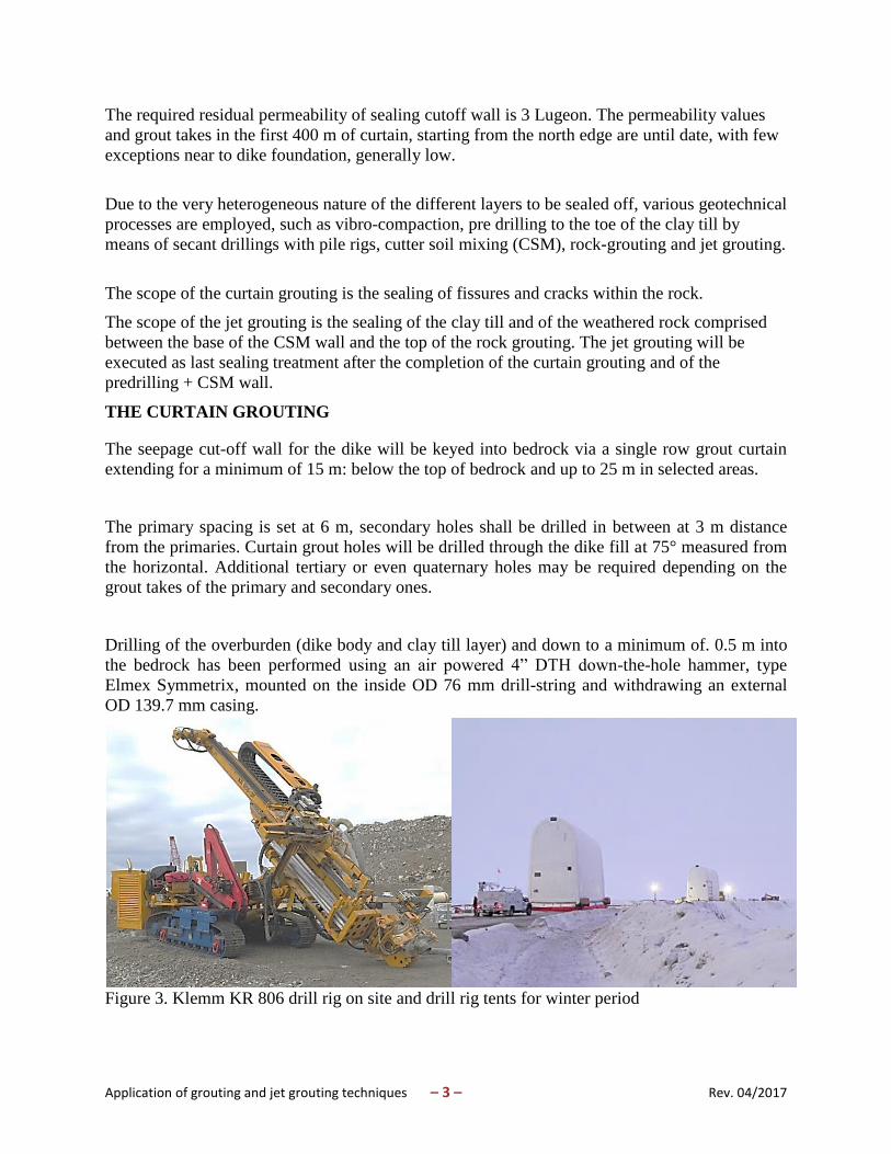
Drilling of the overburden (dike body and clay till layer) and down to a minimum of. 0.5 m into
the bedrock has been performed using an air powered 4” DTH down-the-hole hammer, type
Elmex Symmetrix, mounted on the inside OD 76 mm drill-string and withdrawing an external
OD 139.7 mm casing.
Figure 3. Klemm KR 806 drill rig on site and drill rig tents for winter period
Application of grouting and jet grouting techniques – 4 – Rev. 04/2017
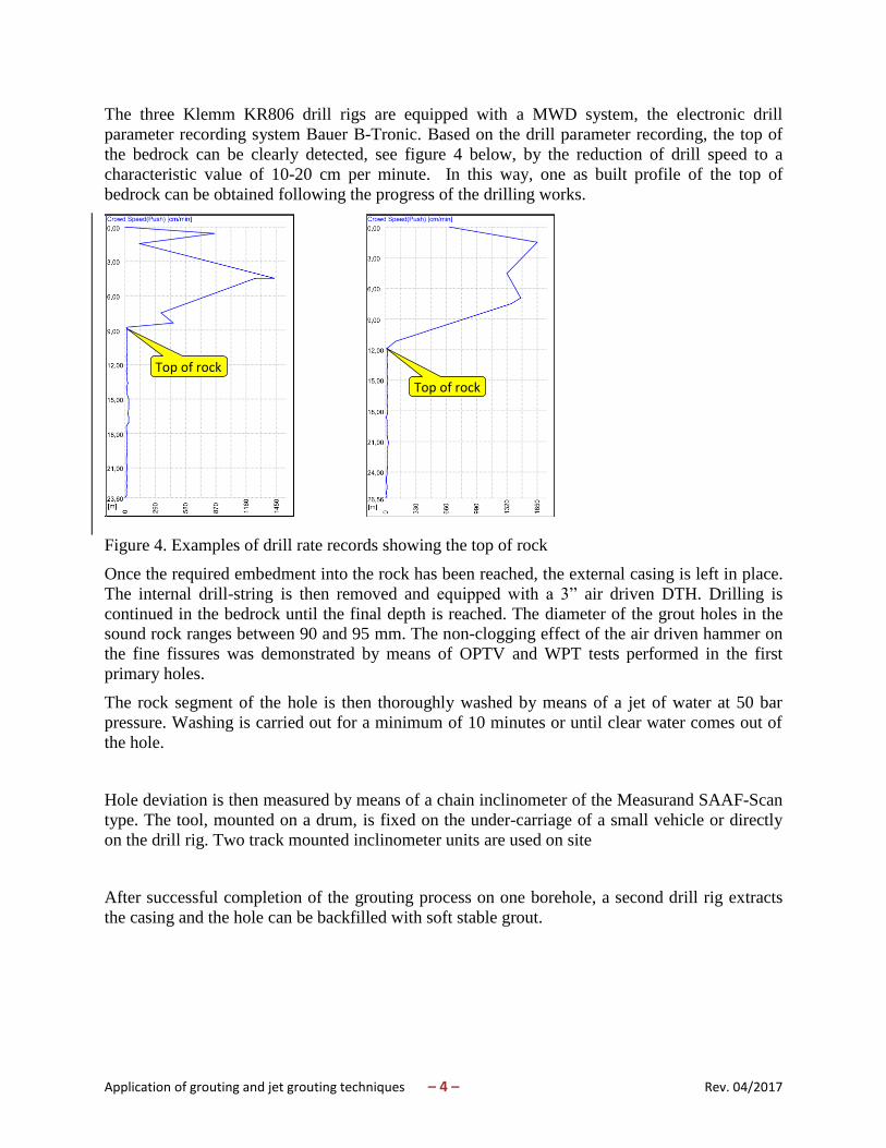
The three Klemm KR806 drill rigs are equipped with a MWD system, the electronic drill
parameter recording system Bauer B-Tronic. Based on the drill parameter recording, the top of
the bedrock can be clearly detected, see figure 4 below, by the reduction of drill speed to a
characteristic value of 10-20 cm per minute. In this way, one as built profile of the top of
bedrock can be obtained following the progress of the drilling works.
Figure 4. Examples of drill rate records showing the top of rock
Once the required embedment into the rock has been reached, the external casing is left in place.
The internal drill-string is then removed and equipped with a 3” air driven DTH. Drilling is
continued in the bedrock until the final depth is reached. The diameter of the grout holes in the
sound rock ranges between 90 and 95 mm. The non-clogging effect of the air driven hammer on
the fine fissures was demonstrated by means of OPTV and WPT tests performed in the first
primary holes.
The rock segment of the hole is then thoroughly washed by means of a jet of water at 50 bar
pressure. Washing is carried out for a minimum of 10 minutes or until clear water comes out of
the hole.
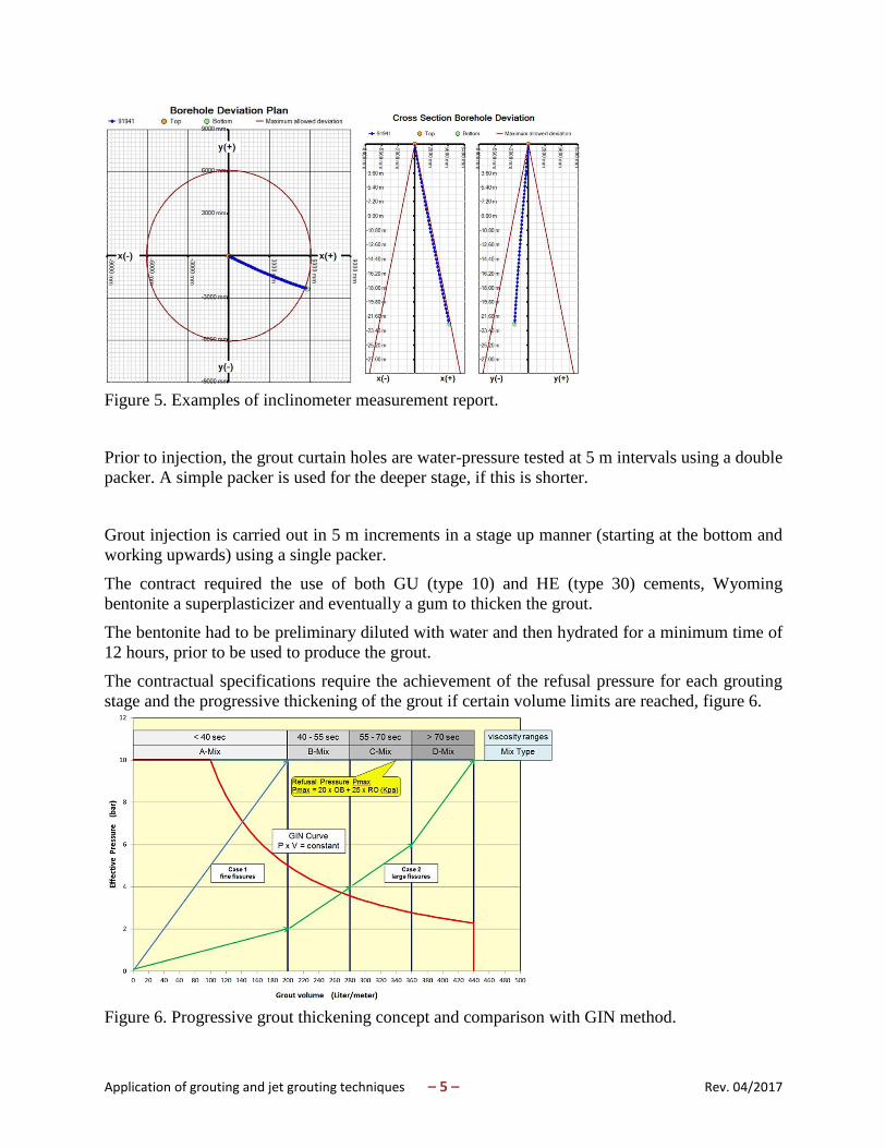
Hole deviation is then measured by means of a chain inclinometer of the Measurand SAAF-Scan
type. The tool, mounted on a drum, is fixed on the under-carriage of a small vehicle or directly
on the drill rig. Two track mounted inclinometer units are used on site
After successful completion of the grouting process on one borehole, a second drill rig extracts
the casing and the hole can be backfilled with soft stable grout.
Top of rock
Top of rock
Application of grouting and jet grouting techniques – 5 – Rev. 04/2017
Figure 5. Examples of inclinometer measurement report.
Prior to injection, the grout curtain holes are water-pressure tested at 5 m intervals using a double
packer. A simple packer is used for the deeper stage, if this is shorter.
Grout injection is carried out in 5 m increments in a stage up manner (starting at the bottom and
working upwards) using a single packer.
The contract required the use of both GU (type 10) and HE (type 30) cements, Wyoming
bentonite a superplasticizer and eventually a gum to thicken the grout.
The bentonite had to be preliminary diluted with water and then hydrated for a minimum time of
12 hours, prior to be used to produce the grout.
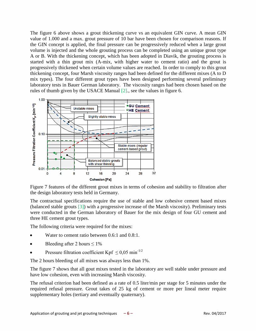
The contractual specifications require the achievement of the refusal pressure for each grouting
stage and the progressive thickening of the grout if certain volume limits are reached, figure 6.
Figure 6. Progressive grout thickening concept and comparison with GIN method.
Application of grouting and jet grouting techniques – 6 – Rev. 04/2017
The figure 6 above shows a grout thickening curve vs an equivalent GIN curve. A mean GIN
value of 1.000 and a max. grout pressure of 10 bar have been chosen for comparison reasons. If
the GIN concept is applied, the final pressure can be progressively reduced when a large grout
volume is injected and the whole grouting process can be completed using an unique grout type
A or B. With the thickening concept, which has been adopted in Diavik, the grouting process is
started with a thin grout mix (A-mix, with higher water to cement ratio) and the grout is
progressively thickened when certain volume values are reached. In order to comply to this grout
thickening concept, four Marsh viscosity ranges had been defined for the different mixes (A to D
mix types). The four different grout types have been designed performing several preliminary
laboratory tests in Bauer German laboratory. The viscosity ranges had been chosen based on the
rules of thumb given by the USACE Manual [2]., see the values in figure 6.
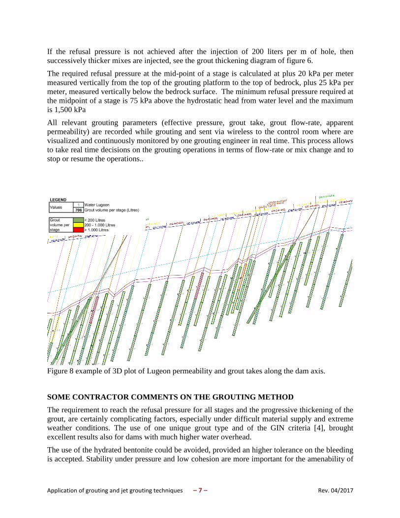
Figure 7 features of the different grout mixes in terms of cohesion and stability to filtration after
the design laboratory tests held in Germany.
The contractual specifications require the use of stable and low cohesive cement based mixes
(balanced stable grouts [3]) with a progressive increase of the Marsh viscosity). Preliminary tests
were conducted in the German laboratory of Bauer for the mix design of four GU cement and
three HE cement grout types.
The following criteria were required for the mixes:
Water to cement ratio between 0.6:1 and 0.8:1.
Bleeding after 2 hours ≤ 1%
Pressure filtration coefficient Kpf ≤ 0,05 min-1/2
The 2 hours bleeding of all mixes was always less than 1%.
The figure 7 shows that all gout mixes tested in the laboratory are well stable under pressure and
have low cohesion, even with increasing Marsh viscosity.
The refusal criterion had been defined as a rate of 0.5 liter/min per stage for 5 minutes under the
required refusal pressure. Grout takes of 25 kg of cement or more per lineal meter require
supplementary holes (tertiary and eventually quaternary).
Application of grouting and jet grouting techniques – 7 – Rev. 04/2017
If the refusal pressure is not achieved after the injection of 200 liters per m of hole, then
successively thicker mixes are injected, see the grout thickening diagram of figure 6.
The required refusal pressure at the mid-point of a stage is calculated at plus 20 kPa per meter
measured vertically from the top of the grouting platform to the top of bedrock, plus 25 kPa per
meter, measured vertically below the bedrock surface. The minimum refusal pressure required at
the midpoint of a stage is 75 kPa above the hydrostatic head from water level and the maximum
is 1,500 kPa
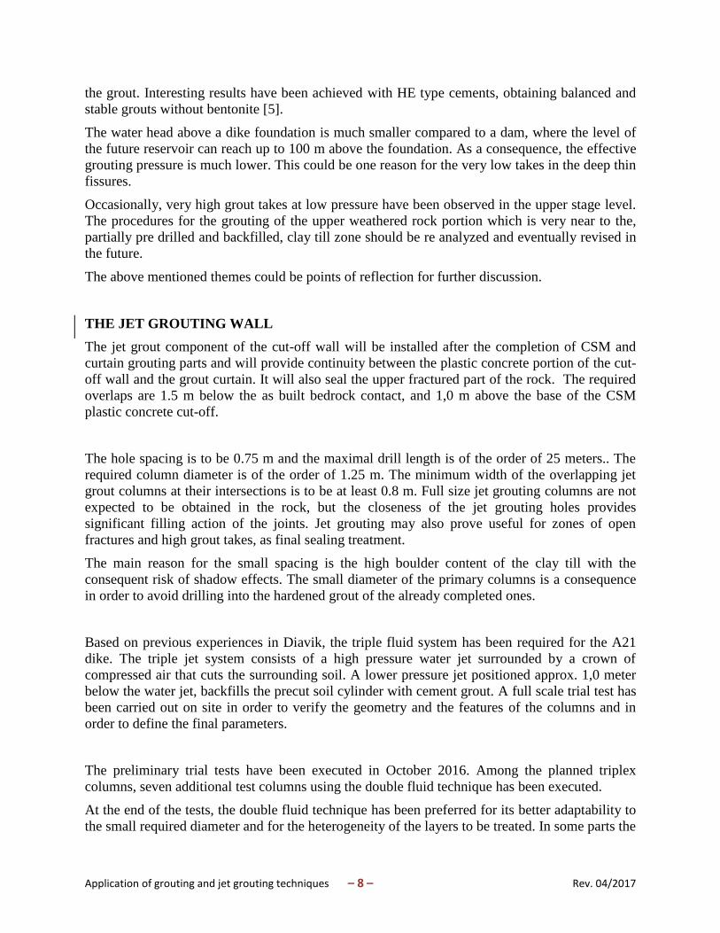
All relevant grouting parameters (effective pressure, grout take, grout flow-rate, apparent
permeability) are recorded while grouting and sent via wireless to the control room where are
visualized and continuously monitored by one grouting engineer in real time. This process allows
to take real time decisions on the grouting operations in terms of flow-rate or mix change and to
stop or resume the operations..
Figure 8 example of 3D plot of Lugeon permeability and grout takes along the dam axis.
SOME CONTRACTOR COMMENTS ON THE GROUTING METHOD
The requirement to reach the refusal pressure for all stages and the progressive thickening of the
grout, are certainly complicating factors, especially under difficult material supply and extreme
weather conditions. The use of one unique grout type and of the GIN criteria [4], brought
excellent results also for dams with much higher water overhead.
The use of the hydrated bentonite could be avoided, provided an higher tolerance on the bleeding
is accepted. Stability under pressure and low cohesion are more important for the amenability of
Application of grouting and jet grouting techniques – 8 – Rev. 04/2017
the grout. Interesting results have been achieved with HE type cements, obtaining balanced and
stable grouts without bentonite [5].
The water head above a dike foundation is much smaller compared to a dam, where the level of
the future reservoir can reach up to 100 m above the foundation. As a consequence, the effective
grouting pressure is much lower. This could be one reason for the very low takes in the deep thin
fissures.
Occasionally, very high grout takes at low pressure have been observed in the upper stage level.
The procedures for the grouting of the upper weathered rock portion which is very near to the,
partially pre drilled and backfilled, clay till zone should be re analyzed and eventually revised in
the future.
The above mentioned themes could be points of reflection for further discussion.
THE JET GROUTING WALL
The jet grout component of the cut-off wall will be installed after the completion of CSM and
curtain grouting parts and will provide continuity between the plastic concrete portion of the cut-
off wall and the grout curtain. It will also seal the upper fractured part of the rock. The required
overlaps are 1.5 m below the as built bedrock contact, and 1,0 m above the base of the CSM
plastic concrete cut-off.
The hole spacing is to be 0.75 m and the maximal drill length is of the order of 25 meters.. The
required column diameter is of the order of 1.25 m. The minimum width of the overlapping jet
grout columns at their intersections is to be at least 0.8 m. Full size jet grouting columns are not
expected to be obtained in the rock, but the closeness of the jet grouting holes provides
significant filling action of the joints. Jet grouting may also prove useful for zones of open
fractures and high grout takes, as final sealing treatment.
The main reason for the small spacing is the high boulder content of the clay till with the
consequent risk of shadow effects. The small diameter of the primary columns is a consequence
in order to avoid drilling into the hardened grout of the already completed ones.
Based on previous experiences in Diavik, the triple fluid system has been required for the A21
dike. The triple jet system consists of a high pressure water jet surrounded by a crown of
compressed air that cuts the surrounding soil. A lower pressure jet positioned approx. 1,0 meter
below the water jet, backfills the precut soil cylinder with cement grout. A full scale trial test has
been carried out on site in order to verify the geometry and the features of the columns and in
order to define the final parameters.
The preliminary trial tests have been executed in October 2016. Among the planned triplex
columns, seven additional test columns using the double fluid technique has been executed.
At the end of the tests, the double fluid technique has been preferred for its better adaptability to
the small required diameter and for the heterogeneity of the layers to be treated. In some parts the
Application of grouting and jet grouting techniques – 9 – Rev. 04/2017
cay till has been substituted by a sandy backfill and that could be destabilized by an high
pressure water jet. Some additional tests will be needed in April 2017, prior to start the
production.
The jet grout mix is designed primarily for erosion resistance , ductility is less of a consideration
given that cut-off wall cracking within the lakebed till is much less consequential than wall
cracking within the Zone 1 core fill.
Based on the above conditions a cement grout with w/c ratio of 1,15 and the addition of 3% of
bentonite on cement weight has been designed for the preliminary tests.
The aimed variation field of the 28 days UC strength of column samples shall range between 2,0
and 6,0 MPa.
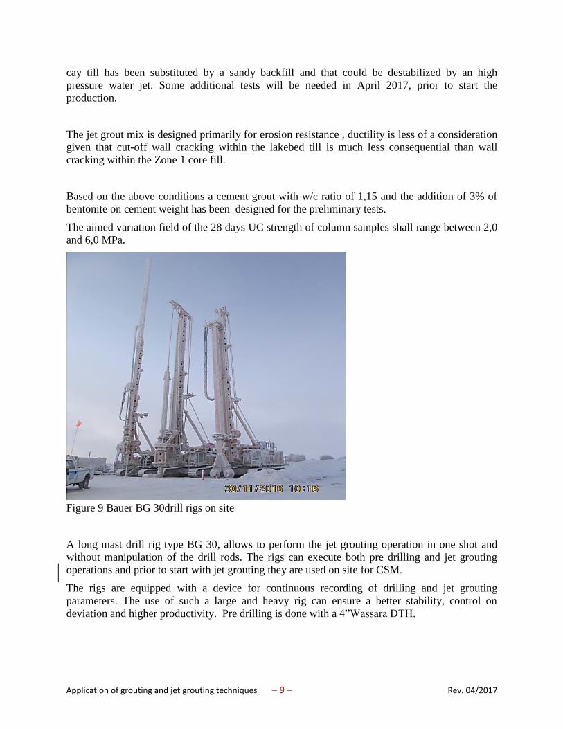
Figure 9 Bauer BG 30drill rigs on site
A long mast drill rig type BG 30, allows to perform the jet grouting operation in one shot and
without manipulation of the drill rods. The rigs can execute both pre drilling and jet grouting
operations and prior to start with jet grouting they are used on site for CSM.
The rigs are equipped with a device for continuous recording of drilling and jet grouting
parameters. The use of such a large and heavy rig can ensure a better stability, control on
deviation and higher productivity. Pre drilling is done with a 4”Wassara DTH.

Application of grouting and jet grouting techniques – 10 – Rev. 04/2017
Bore-hole deviation will be measured on every hole after the final depth is achieved. The
planned logging tool is a chain inclinometer type SAAScan of Canadian Supplier Measurand Inc.
The tool consists of many 50 cm long segments. The segments are connected in a chain and are
mounted on a drum which will be fixed at the undercarriage of a small vehicle.
The realization of the jet grouting wall is foreseen for 2017 season. The jet grouting will be a
very concentrated operation, since requires the parallel employ of up to five heavy drill rigs from
the type BG30, working around the clock. This will be a logistical and technical challenge for the
site.
CONCLUSIONS
Some of the practical aspects of the grouting and jet grouting works have been analyzed from the
contractor point of view.
Grouting is slowly progressing though very tough winter weather. More than 70% of the planned
holes have been completed by the end of December. Grouting has shown until now, with few
exceptions, quite low permeability values and grout takes. The average grout take over the 1.550
grouting stages performed to the end of December is 22 Liters/m. Only 3% of grouting stages
had takes of more than 100 Liter/m. The stages showing high grout takes are almost all located
near to the top of rock. The grouting process has terminated in more than 90% of the cases with
the thin grout type A. The first cored control hole have shown permeability values below 1 UL.
The first jet grouting field trial test has brought to the choice of the double system as favorite jet
grouting method. Due to the planned narrow spacing between the primary holes, the diameter of
the primary columns shall not be larger than 1,25 m. A wider range of column diameters shall
then be tested in a further test stage, prior to production phase.
REFERENCES
[1]. Golder Associates (2015) A21 project 2015 Hydrogeological and Geotechnical Field
Investigation Factual Report .
[2]. DEPARTMENT OF THE ARMY U.S. Army Corps of Engineers (2014) Engineering and
Design Grouting Technology Manual No. EM 1110-2-3506
[3], De Paoli, B., Bosco, B., Granata, R. and Bruce, D.A. (1992). Fundamental Observations on
Cement Based Grouts (1): Microfine Cements and the Cemill Process. Proc. ASCE
Conference, “Grouting, Soil Improvement and Geosynthetics, New Orleans, LA,. Feb.
25-28, 2 Volumes, pp. 474-485.
[4], Cliff Kettle & Maren Katterbach Practical application of the GIN concept (Part 1) The
Grout Line Geotechnical News December 2015
[5]. Vafa Rombough, Grant Bonin, Dawn Shuttle (2006) Penetrability Control of GIN Mixes
during Fractured Rock Grouting Sea to Sky Geotechnique