l 21 grouting. - nptel.ac.in · jet grouting •jet grouting is a grouting technique that creates...
TRANSCRIPT
GROUND IMPROVEMENTGROUND TREATMENT
USING GROUTING
NPTEL Course
Prof. G L Sivakumar BabuDepartment of Civil EngineeringIndian Institute of ScienceBangalore 560012Email: [email protected]
Lecture 21
Chemical grouting is defined as any grouting materialcharacterized by being a pure solution; no particles insuspension (Committee on Grouting 1980). In practice,suspended solids are often added to chemical grouts to modify the solution properties as additives. The types of chemical grouting materials have been classified into six categories by Karol (2003): Sodium silicate formulations; acrylics; lignosulfites-lignosulfonates; phenoplasts; aminoplasts; and other materials.
Chemical grouting
Chemical GroutingChemical grouting is a ground treatment method for soilswith a relatively low-viscosity grout. There are many typesof chemical grout, each having different strength, cost,viscosity, toxicity and durability.The major difference between particulate grouts and chemical grouts is in the penetrability. Chemical grouts can penetrate into soil with finer particles. The penetrability for chemical grouts is a function of the solution viscosity whereas the penetrability for particulate grouts is a function of particle size.
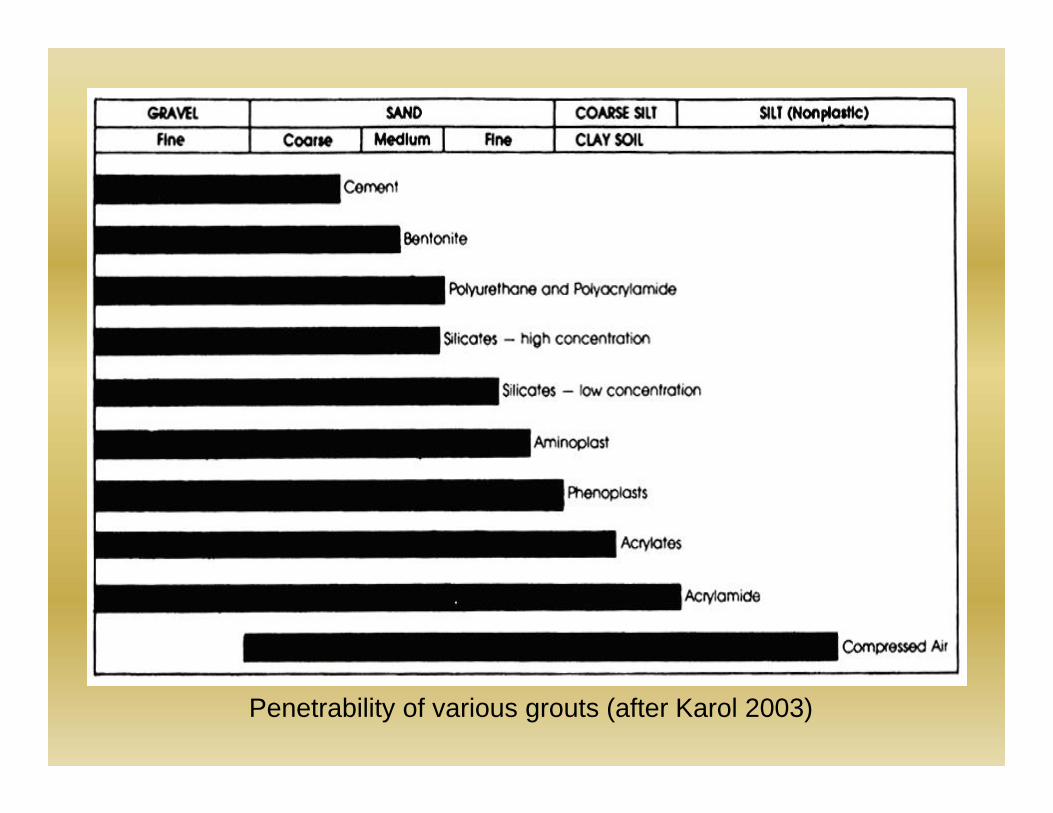
Penetrability of various grouts (after Karol 2003)
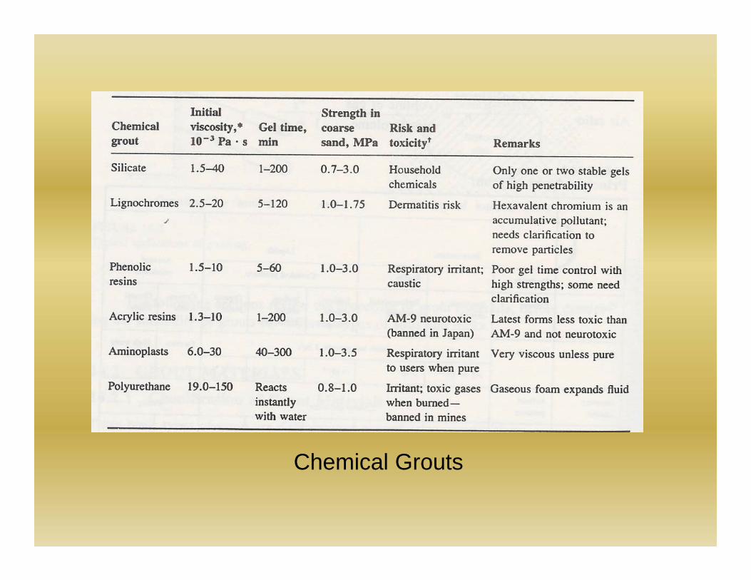
Chemical Grouts
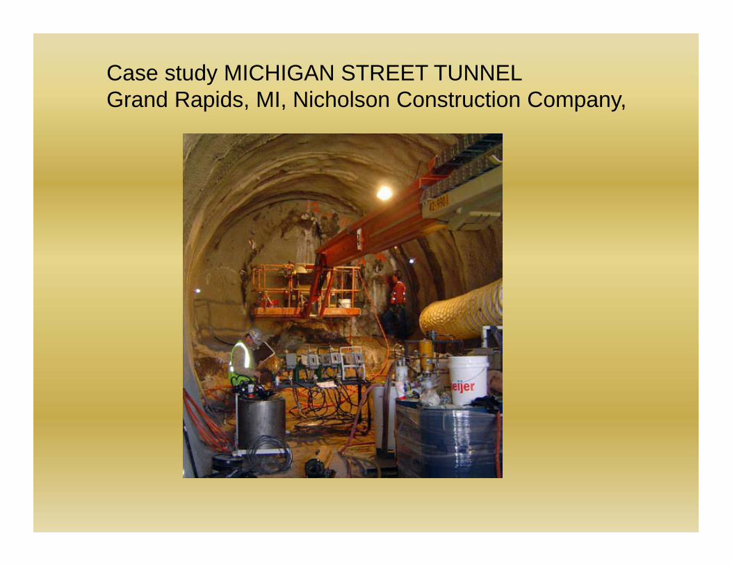
Case study MICHIGAN STREET TUNNELGrand Rapids, MI, Nicholson Construction Company,
The 31m -long,6m dia tunnel was constructed using the New Austrian Tunneling Method. Because the site’s ground conditions primarily consist of fine sand, chemical grouting was specified to stabilize the sand and enable openface tunneling. Nicholson treated 3,425 cubic yards of sand with a sodium-silicate-based grout. The chemical grout was injected through 41 tube-a-manchette (TAM) sleeves, each one over 100 feet long. The TAM sleeves were drilled horizontally in order to maintain an active, undisturbed roadway above. The chemical grouting process created a treated mass of stabilized sand so the tunnel could be excavated with less risk of overburden collapse.
Studies are available to confirm the longevity of the chemical grouting in controlling infiltration and inflow of underground water in underground structures.
The treatment did not show any signs of distress, withstood number of cycles of weathering as well as cost effective.
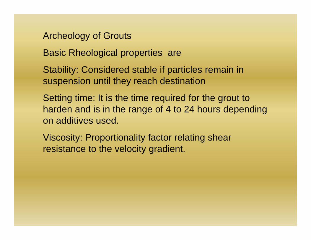
Archeology of Grouts
Basic Rheological properties are
Stability: Considered stable if particles remain in suspension until they reach destination
Setting time: It is the time required for the grout to harden and is in the range of 4 to 24 hours depending on additives used.
Viscosity: Proportionality factor relating shear resistance to the velocity gradient.
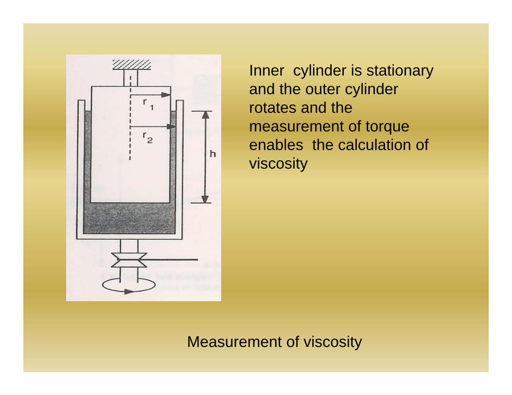
Measurement of viscosity
Inner cylinder is stationary and the outer cylinder rotates and the measurement of torque enables the calculation of viscosity
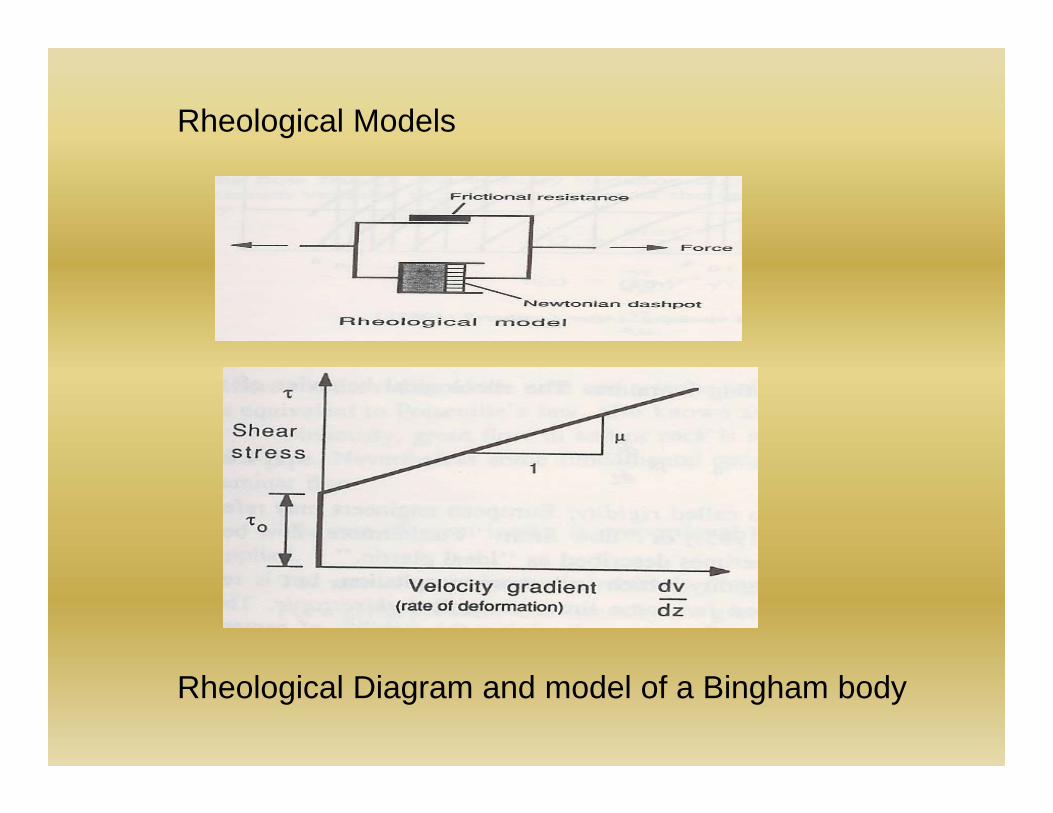
Rheological Models
Rheological Diagram and model of a Bingham body
0dvdz
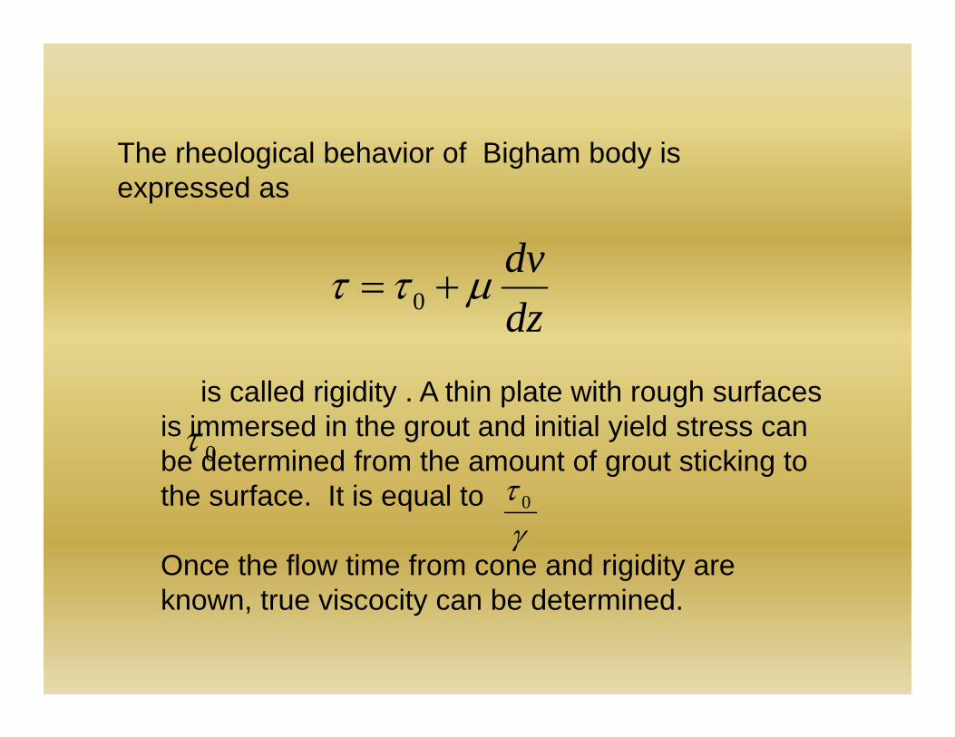
The rheological behavior of Bigham body is expressed as
0is called rigidity . A thin plate with rough surfaces
is immersed in the grout and initial yield stress can be determined from the amount of grout sticking to the surface. It is equal to
Once the flow time from cone and rigidity are known, true viscocity can be determined.
0
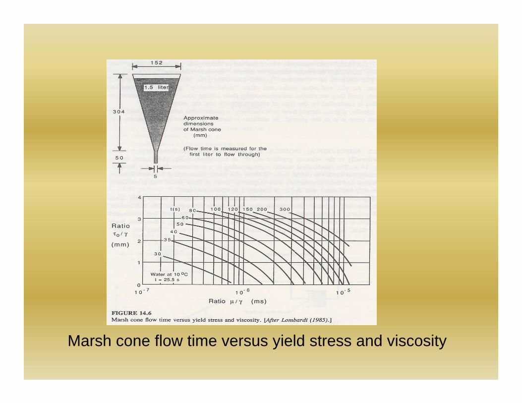
Marsh cone flow time versus yield stress and viscosity
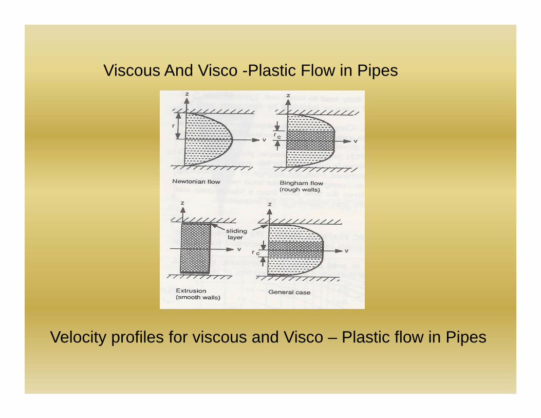
Viscous And Visco -Plastic Flow in Pipes
Velocity profiles for viscous and Visco – Plastic flow in Pipes
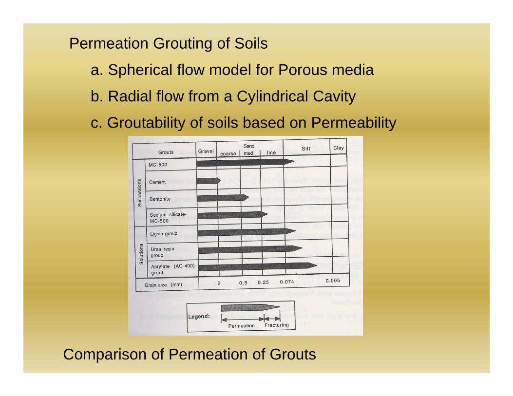
Permeation Grouting of Soils
a. Spherical flow model for Porous media
b. Radial flow from a Cylindrical Cavity
c. Groutability of soils based on Permeability
Comparison of Permeation of Grouts
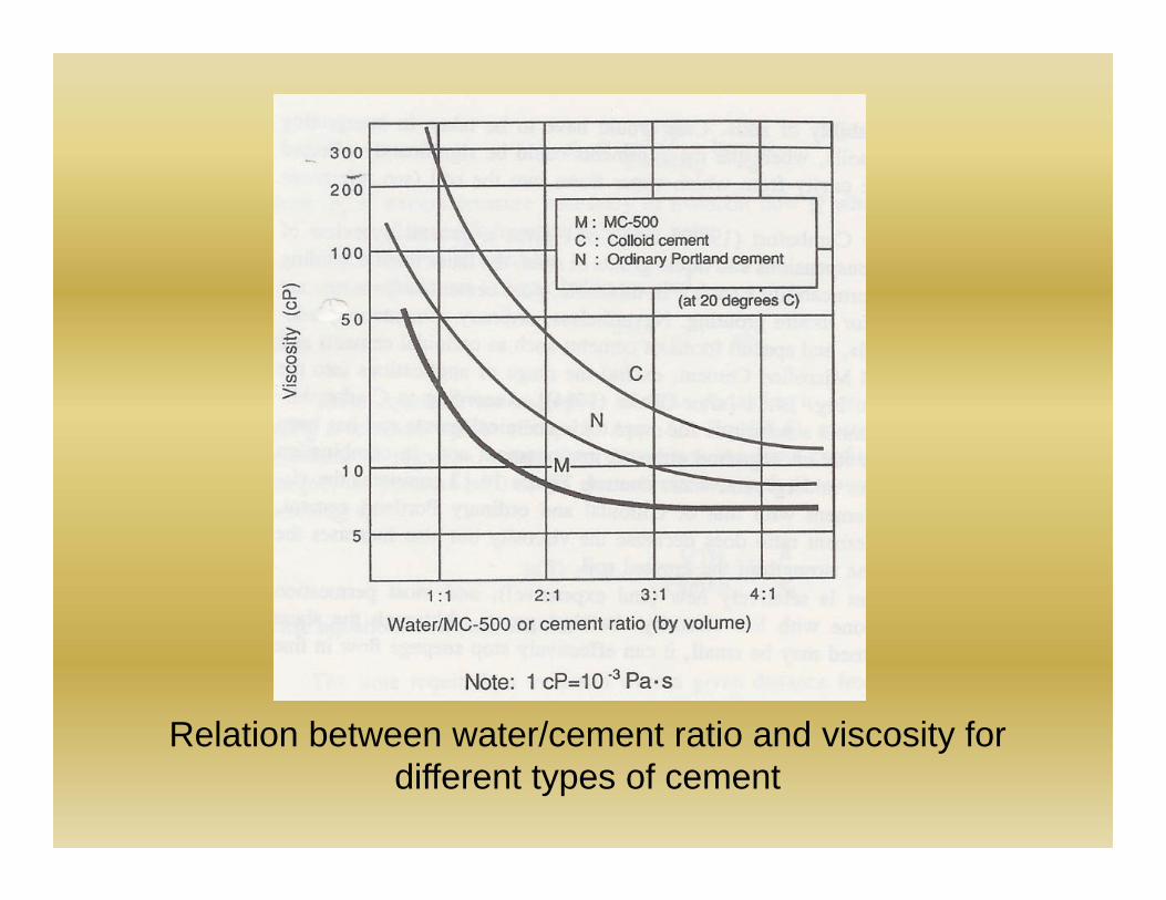
Relation between water/cement ratio and viscosity for different types of cement
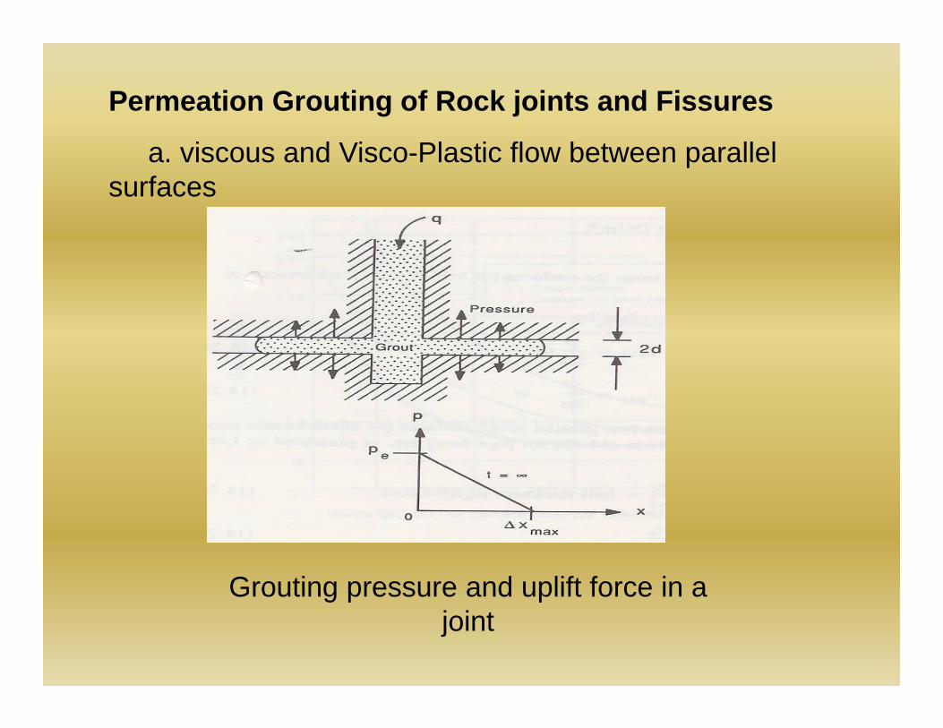
Permeation Grouting of Rock joints and Fissures
a. viscous and Visco-Plastic flow between parallel surfaces
Grouting pressure and uplift force in a joint
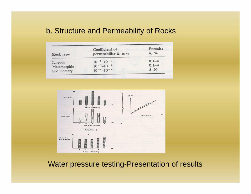
b. Structure and Permeability of Rocks
Water pressure testing-Presentation of results
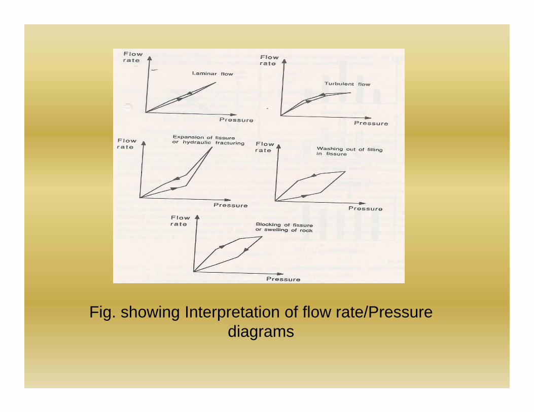
Fig. showing Interpretation of flow rate/Pressure diagrams
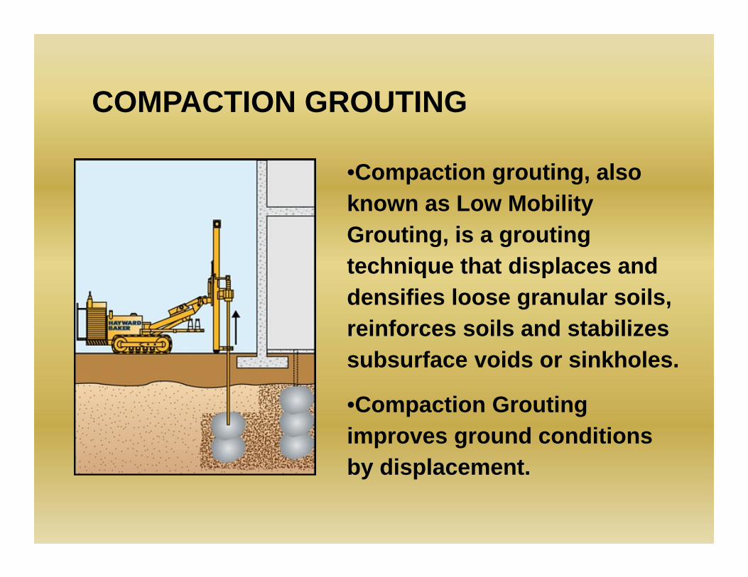
COMPACTION GROUTING
•Compaction grouting, also known as Low Mobility Grouting, is a grouting technique that displaces and densifies loose granular soils, reinforces soils and stabilizes subsurface voids or sinkholes.
•Compaction Grouting improves ground conditions by displacement.
Site Investigation•Comprehensive knowledge of subsurface conditions is important.
•A site investigation report generally contain site geology and history, soil gradation and the in situ horizontal permeability of each treatment stratum.
•Type and condition of nearby structure and utilities, together with plan and elevation location, will further assist program development.
Geotechnical Considerations1. The in situ vertical stress in the treatment stratum
must be sufficient to enable the grout to displace the soil horizontally.
2. The grout injection rate should be slow enough to allow pore pressure dissipation.
3. Compaction grouting can usually be effective in most silts and sands, provided that the soil is not near saturation.
4. Soils that lose strength during remolding should be avoided.
5. Greater displacement will occur in weaker soil strata. Excavated grout bulbs confirm that compaction grouting focuses improvement where it is most needed.
6. Collapsible soils can usually be treated effectively by adding water during drilling prior to compaction grout injection.
7. Stratified soils, particularly thinly stratified soils, can be cause for difficult or reduced improvement capability.
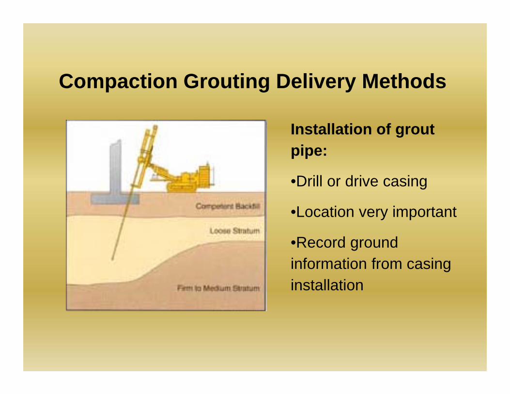
Compaction Grouting Delivery Methods
Installation of grout pipe:
•Drill or drive casing
•Location very important
•Record ground information from casing installation
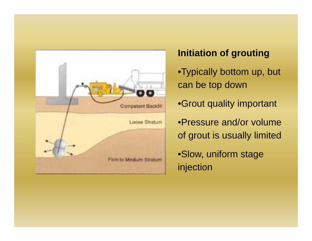
Initiation of grouting
•Typically bottom up, but can be top down
•Grout quality important
•Pressure and/or volume of grout is usually limited
•Slow, uniform stage injection
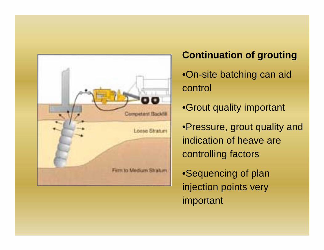
Continuation of grouting
•On-site batching can aid control
•Grout quality important
•Pressure, grout quality and indication of heave are controlling factors
•Sequencing of plan injection points very important
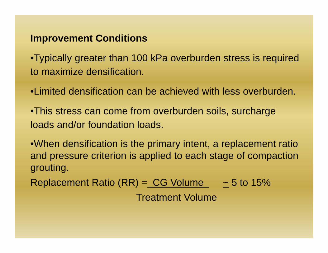
Improvement Conditions
•Typically greater than 100 kPa overburden stress is required to maximize densification.
•Limited densification can be achieved with less overburden.
•This stress can come from overburden soils, surcharge loads and/or foundation loads.
•When densification is the primary intent, a replacement ratio and pressure criterion is applied to each stage of compaction grouting.Replacement Ratio (RR) = CG Volume ~ 5 to 15%
Treatment Volume
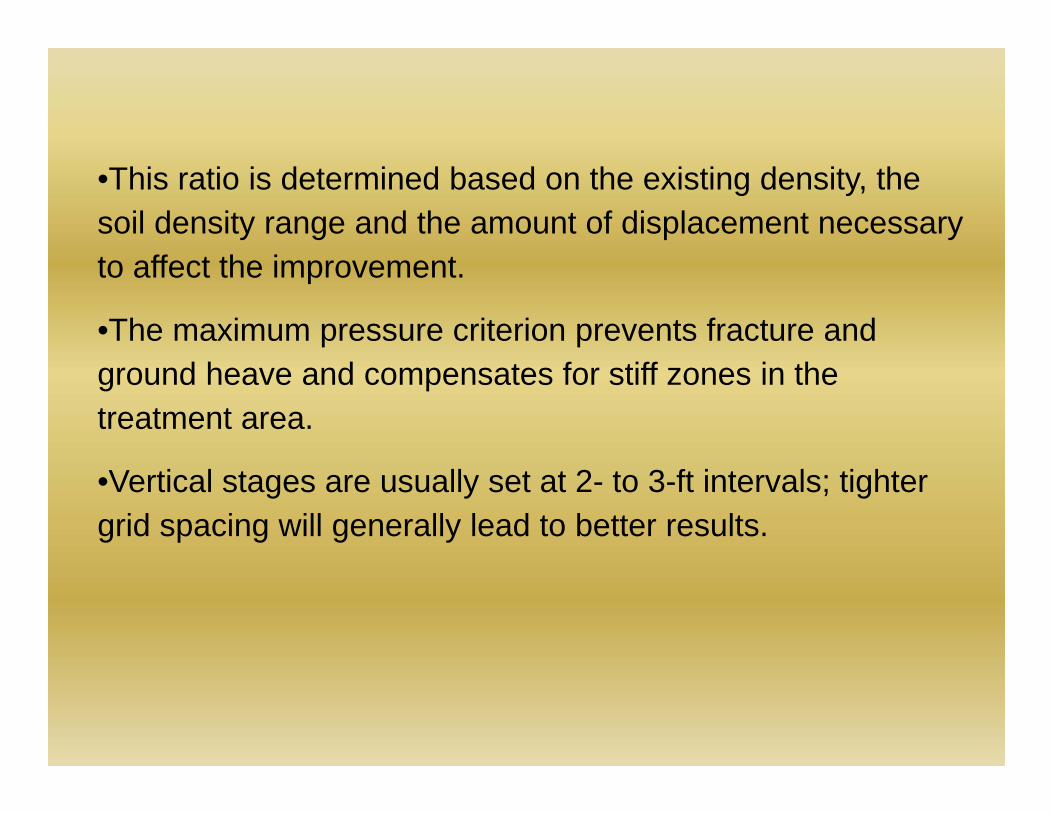
•This ratio is determined based on the existing density, the soil density range and the amount of displacement necessary to affect the improvement.
•The maximum pressure criterion prevents fracture and ground heave and compensates for stiff zones in the treatment area.
•Vertical stages are usually set at 2- to 3-ft intervals; tighter grid spacing will generally lead to better results.
Applications
Karstic Regions
•Pre-treatment for prevention of potential sinkholes is common
•Pre-treatment usually involves drilling down to and into the limestone surface to locate and fill any cavities, followed by improvement of the loose soil above the rock surface.
Rubble Fill
•Construction debris and other similar fills are often placed in an uncontrolled manner.
•To close the void spaces and minimize potential settlement impact, compaction grouting is applied in a regular pattern.
Poorly Placed Fill
•Provided sufficient overburden stress exists, a proper program of compaction grouting can treat the poorly placed fill material.
Loosened Soil: Pre-Treatment
•Construction-generated ground disturbance can often be the cause of soil loosening near the work area and can affect nearby structure.
•The injection of compaction grout soon after the disturbance occurs can compensate for the disturbance by re-establishing the original stress state and prevent deformations beyond the work area.
Liquefiable Soils
•Ground improvement consists of density increase, cellular containment, and/or reinforcement.
•Sol permeability is an important parameter in determining the rate of compaction grouting.
Collapsible Soils
•Collapsible soil conditions exist in specific regions where wind-blown silts have accumulated or intermittent stream flow deposition has occurred.
•Treatment of this soils is possible by forcing a restructuring of the fine grains into a tighter configuration.
Advantages of Compaction Grouting• pinpoint treatment
• Speed of installation
• Wide application range
• Effective in a variety of soil conditions
• Can be performed in very tight access and low headroom conditions
• Non-hazardous
• No waste spoil disposal
• No need to connect to footing or column
•Non-destructive and adaptable to existing foundations
•Economic alternative to removal and replacement or piling
•Able to reach depths unattainable by other methods
•Enhanced control and effectiveness of in situ treatment with Denver System
Case study:McClellan Pump Station Littleton, Colorado:Construction of waste water lift station at theMcClellan pump station included the sinking of 40-ftdeep, 30-ft diameter shaft through uncompactednative, silt sands.
The shaft was designed as a series of 10-ft deepconcrete ring sections installed from that top down,with the bottom of the shaft reaching design elevationat 40-ft below grade.
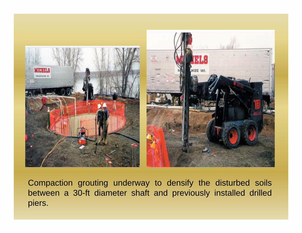
Compaction grouting underway to densify the disturbed soilsbetween a 30-ft diameter shaft and previously installed drilledpiers.
Some unanticipated problems were faced during theconstruction process.
The problem due to side friction was overcome byair and water jetting.
Additional fill was placed to restore the site to grade.And the shaft was then completed.
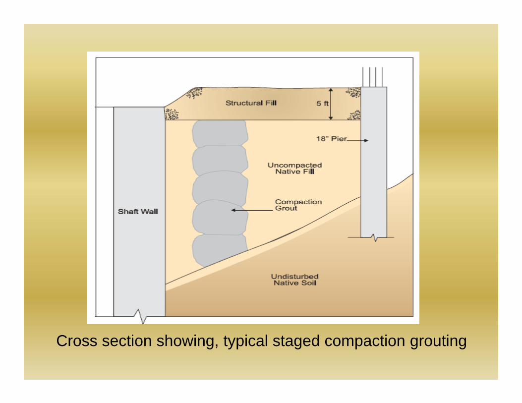
Cross section showing, typical staged compaction grouting
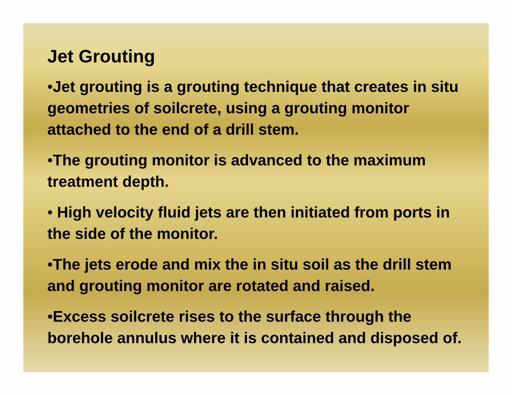
Jet Grouting•Jet grouting is a grouting technique that creates in situ geometries of soilcrete, using a grouting monitor attached to the end of a drill stem.
•The grouting monitor is advanced to the maximum treatment depth.
• High velocity fluid jets are then initiated from ports in the side of the monitor.
•The jets erode and mix the in situ soil as the drill stem and grouting monitor are rotated and raised.
•Excess soilcrete rises to the surface through the borehole annulus where it is contained and disposed of.
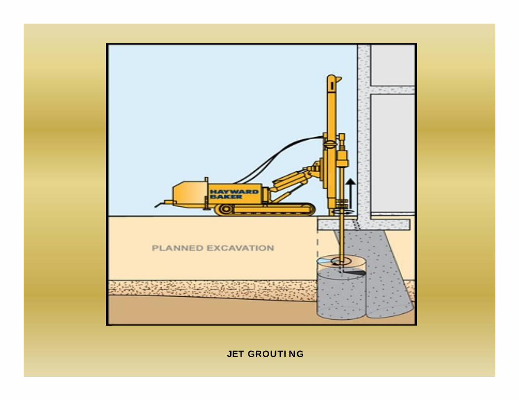
JET GROUTING
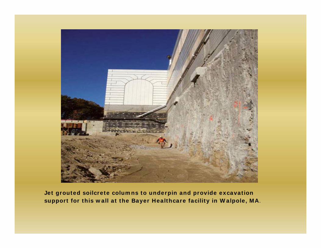
Jet grouted soilcrete columns to underpin and provide excavation support for this wall at the Bayer Healthcare facility in Walpole, MA.
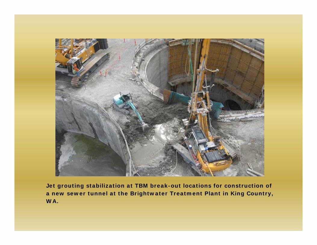
Jet grouting stabilization at TBM break-out locations for construction of a new sewer tunnel at the Brightwater Treatment Plant in King Country, WA.
Depending on the application and soils to be treated, there are three primary systems of jet grouting: •The single fluid system (Soilcrete S): the injection of cementitious grout slurry at high velocity to erode and mix with soil.•The double fluid system (Soilcrete D): the injection of cementitious grout slurry at high velocity, sheathed in a cone of air at an equally high velocity, to erode and mix with soil.•The triple fluid system (Soilcrete T): the injection of water at high velocity, sheathed in a cone of air at an equally high velocity, to erode the soil while simultaneously tremieinjecting a cementitious grout slurry from beneath the erosion jets.
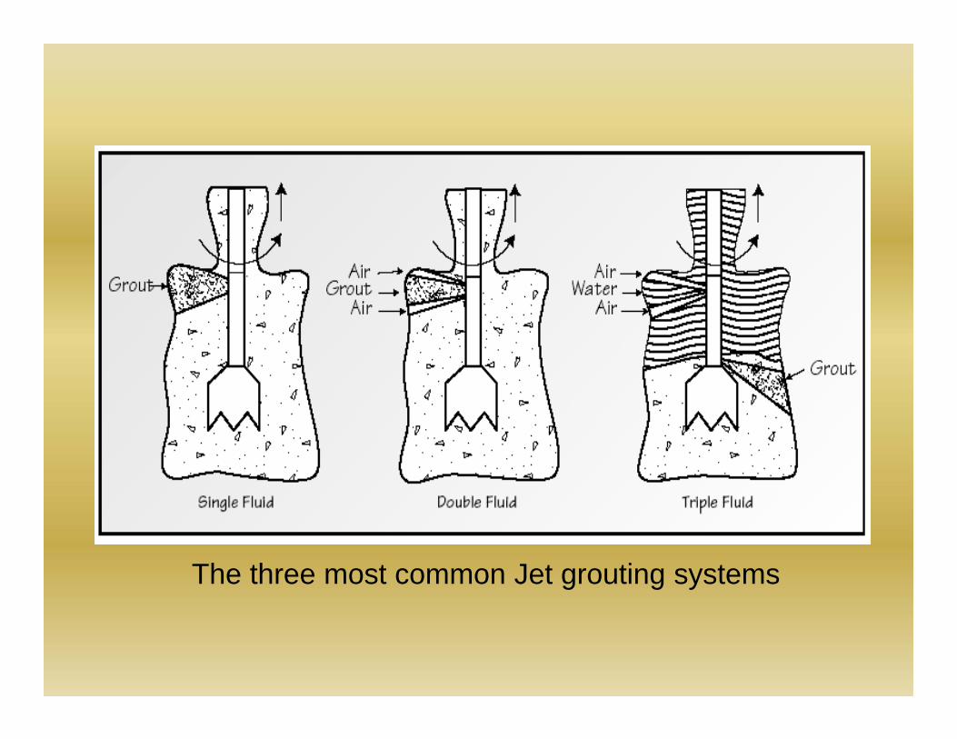
The three most common Jet grouting systems
There are more variations of these systems than there are systems themselves, but in most cases they are a “bottom-up” process. That is to say, they use hydraulic rotary drilling to reach the design depth, and at that point initiate jet grouting parameters and procedure to create a cementitious soil matrix commonly called soilcrete.
During grouting, the borehole annulus must be large enough to permit unimpeded up-hole spoil return. this allows for control of the in situ stress environment. A lack of this spoil return will result in hydrofracturing the ground and loss of control. Loss of this control can lead to extreme inconsistencies in the soilcrete quality and geometry.
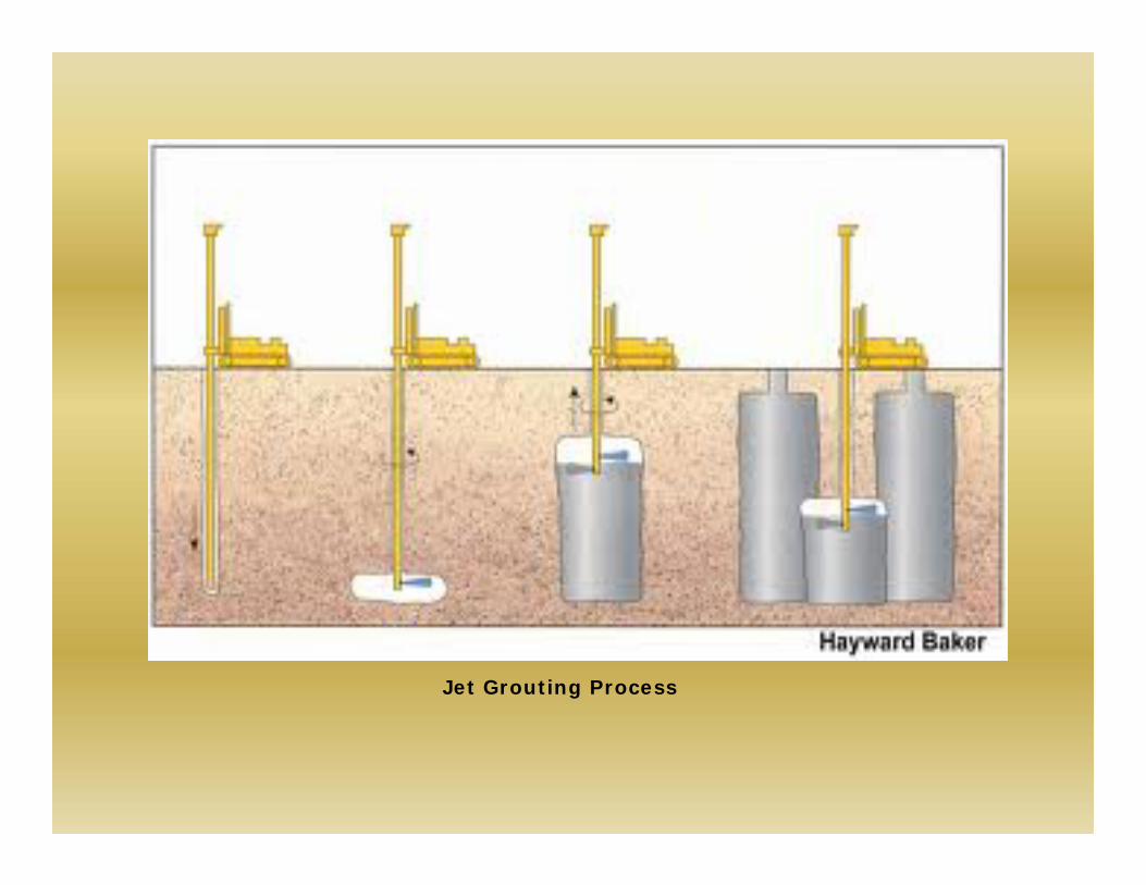
Jet Grouting Process
Jet Grouting Procedure
Predrilling or foundation coring may be necessary to access the treatment zone. Other emerging jet grouting systems include SuperJet and X-Jet grouting.
•SuperJet System: a double fluid system reliant on specialized tooling and high injection energy for enhanced erosion capability (up to 5m diameter)
•X-Jet System: a triple fluid system using a pair of colliding erosion jets to create a more uniform and controlled diameter of treatment.
Concluding Remarks
Grouting is a versatile technique and has been proven to be suitable to many ground improvement applications.

References
Hausmann M R (1984) Engineering principles of Ground Modification.Schafer et al (1997) Ground Improvement, Ground Reinforcement, and Ground Treatment- Developments; 1987-1997, Geotechnical Special Publication; No 69. Jian Chu (2009) Construction Processes, State of the Art Report, ICSMGE, Alexandria, Egypt.