stuctues - atkins/media/files/a/atkins-corporate/grou… · analysis, to confirm the findings of...
TRANSCRIPT
The strengthening of Irwell Valley Bridge
005STR
UC
TUR
ES
41
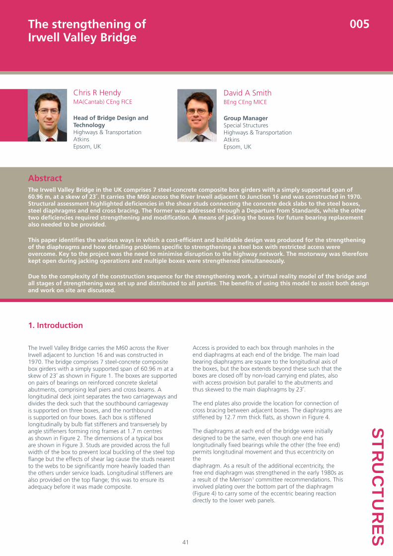
AbstractThe Irwell Valley Bridge in the UK comprises 7 steel-concrete composite box girders with a simply supported span of 60.96 m, at a skew of 23˚. It carries the M60 across the River Irwell adjacent to Junction 16 and was constructed in 1970. Structural assessment highlighted deficiencies in the shear studs connecting the concrete deck slabs to the steel boxes, steel diaphragms and end cross bracing. The former was addressed through a Departure from Standards, while the other two deficiencies required strengthening and modification. A means of jacking the boxes for future bearing replacement also needed to be provided.
This paper identifies the various ways in which a cost-efficient and buildable design was produced for the strengthening of the diaphragms and how detailing problems specific to strengthening a steel box with restricted access were overcome. Key to the project was the need to minimise disruption to the highway network. The motorway was therefore kept open during jacking operations and multiple boxes were strengthened simultaneously.
Due to the complexity of the construction sequence for the strengthening work, a virtual reality model of the bridge and all stages of strengthening was set up and distributed to all parties. The benefits of using this model to assist both design and work on site are discussed.
Chris R HendyMA(Cantab) CEng FICE
Head of Bridge Design and Technology Highways & TransportationAtkinsEpsom, UK
David A SmithBEng CEng MICE
Group ManagerSpecial StructuresHighways & TransportationAtkinsEpsom, UK
1. Introduction
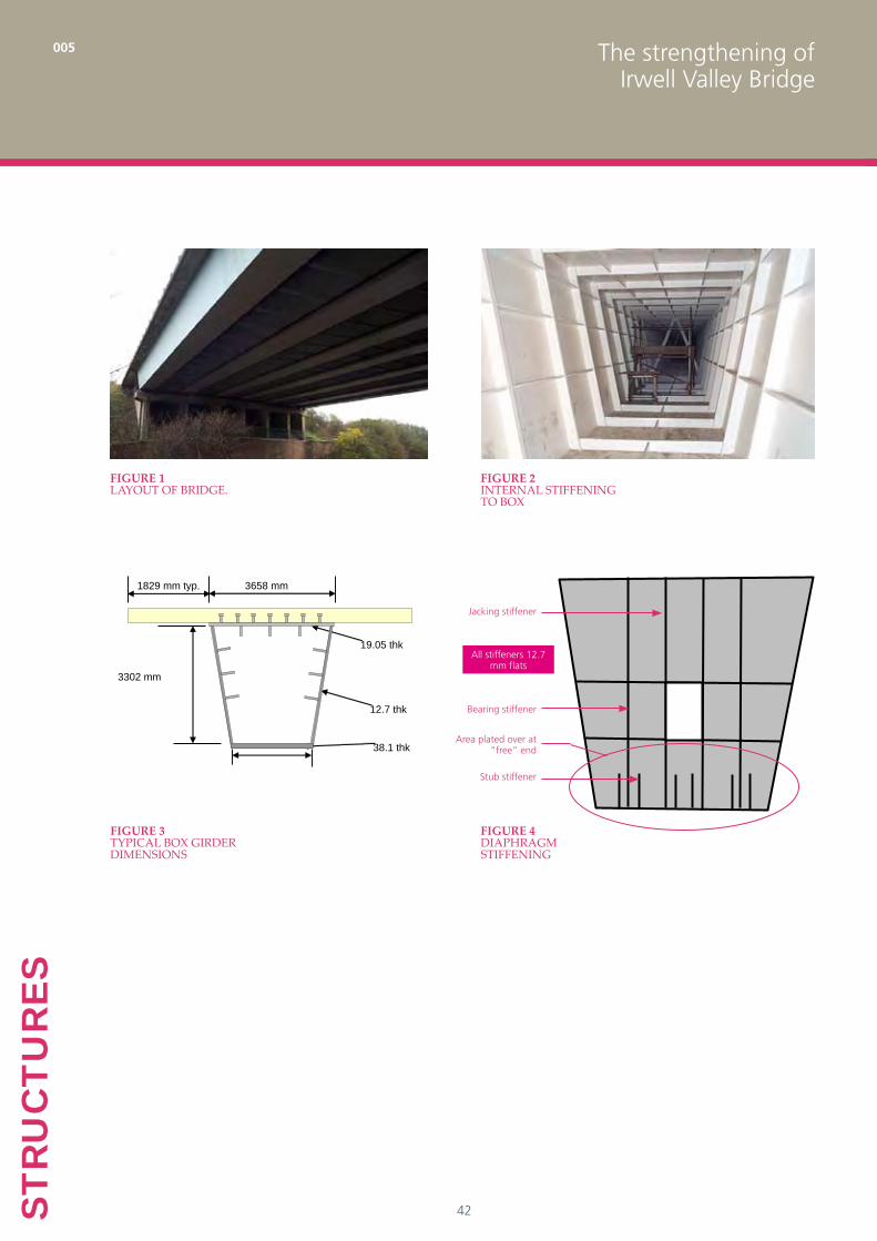
The Irwell Valley Bridge carries the M60 across the River Irwell adjacent to Junction 16 and was constructed in 1970. The bridge comprises 7 steel-concrete composite box girders with a simply supported span of 60.96 m at a skew of 23˚ as shown in Figure 1. The boxes are supported on pairs of bearings on reinforced concrete skeletal abutments, comprising leaf piers and cross beams. A longitudinal deck joint separates the two carriageways and divides the deck such that the southbound carriageway is supported on three boxes, and the northbound is supported on four boxes. Each box is stiffened longitudinally by bulb flat stiffeners and transversely by angle stiffeners forming ring frames at 1.7 m centres as shown in Figure 2. The dimensions of a typical box are shown in Figure 3. Studs are provided across the full width of the box to prevent local buckling of the steel top flange but the effects of shear lag cause the studs nearest to the webs to be significantly more heavily loaded than the others under service loads. Longitudinal stiffeners are also provided on the top flange; this was to ensure its adequacy before it was made composite.
Access is provided to each box through manholes in the end diaphragms at each end of the bridge. The main load bearing diaphragms are square to the longitudinal axis of the boxes, but the box extends beyond these such that the boxes are closed off by non-load carrying end plates, also with access provision but parallel to the abutments and thus skewed to the main diaphragms by 23˚.
The end plates also provide the location for connection of cross bracing between adjacent boxes. The diaphragms are stiffened by 12.7 mm thick flats, as shown in Figure 4.
The diaphragms at each end of the bridge were initially designed to be the same, even though one end has longitudinally fixed bearings while the other (the free end) permits longitudinal movement and thus eccentricity on the diaphragm. As a result of the additional eccentricity, the free end diaphragm was strengthened in the early 1980s as a result of the Merrison1 committee recommendations. This involved plating over the bottom part of the diaphragm (Figure 4) to carry some of the eccentric bearing reaction directly to the lower web panels.
The strengthening of Irwell Valley Bridge
005
42STR
UC
TUR
ES
3302 mm
3658 mm
12.7 thk
19.05 thk
38.1 thk
1829 mm typ.
Figure 1Layout of bridge.
Figure 2internaL stiffening to box
Figure 3typicaL box girder dimensions
Jacking stiffener
Bearing stiffener
Stub stiffener
Area plated over at “free” end
All stiffeners 12.7 mm flats
Figure 4diaphragm stiffening

The strengthening of Irwell Valley Bridge
005
43
STRU
CTU
RES
2. History of assessment
Structural assessment of the bridge was originally carried out by Parkman over a number of years to BD 562 and BD 613. The main boxes were generally found to be adequate in shear and flexure but deficiencies were found in the following areas:
Shear studs connecting the concrete deck slabs to the • steel boxes
Steel diaphragms•
End cross bracing•
The concrete abutments were not assessed, despite being significant spanning members in their own right. They were deemed to be satisfactory on the basis of visual inspection.
Shear studs
The shear studs were found to have inadequate fatigue life due to the uneven distribution of stud force across the box determined from BD 61 as indicated diagrammatically in Figure 5. This distribution depends on shear lag and stud stiffness. The formula in BD 61 is based on stud stiffness values assumed by Moffat and Dowling4. Finite element analysis with more realistic stud stiffnesses leads to a more uniform distribution of stud force (as given in Hendy and Johnson5 for example). Parkman commissioned such an analysis which resulted in the studs being shown to be adequate. As a result of the theoretical overstress and to justify this Departure from Standards, acoustic monitoring equipment was installed on the bridge. After extensive monitoring and subsequent testing of core specimens, no fatigue damage to any studs was found.
Of greater concern was the lack of any transverse reinforcement in the bottom layer of the deck slab across the box top flange. Reinforcement is typically needed to prevent splitting of the concrete ahead of the stud and to control the spread of force across the slab. This deficiency was accepted on the basis of inspections of the slab which found no longitudinal cracks and also a further assessment by Atkins which ignored the shear connection other than in its role of preventing top flange buckling. This indicated that the box would not collapse under live load (with unity partial material and load factors).
Diaphragm bearing stiffeners
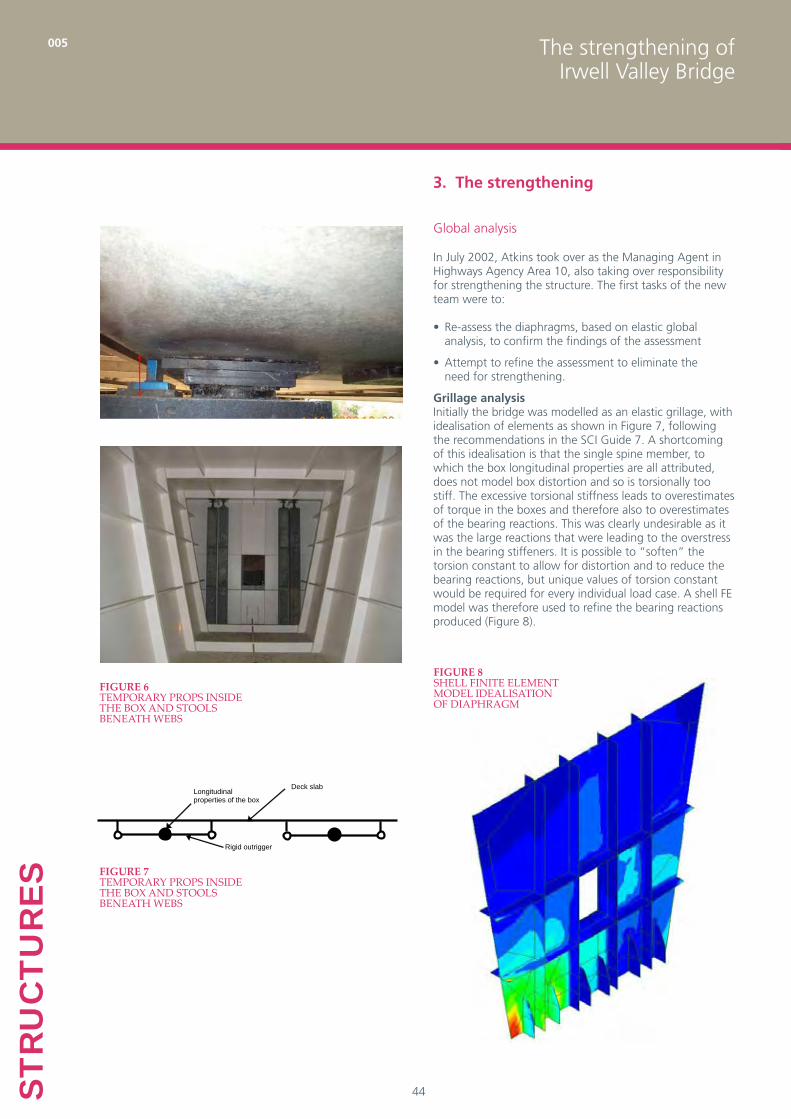
The critical assessed elements on the bridge were found to be the diaphragm bearing stiffeners – see Figure 4. These were rated at “dead load only”, governed by predicted failures in both buckling and yielding. The central stiffeners adjacent to the access hole were also considerably overstressed if assumed to form “jacking stiffeners” in the event of needing to replace the bridge’s bearings. The diaphragm assessment was initially based on BS 5400:Part 36 Clause 9.17, but subsequent assessment used elastic FE analysis. Interim measures were taken to keep the bridge open. Parkman installed temporary props inside the box and stools beneath the webs outside the box (Figure 6) as an interim measure.
Bracing
The cross bracing at the ends of the deck are unnecessary for the adequacy of the bridge because the boxes are themselves torsionally restrained by their seating on pairs of bearings. The skew of the bracing relative to the axes of the boxes meant they attracted significant forces due to rotation of the boxes about a horizontal axis, thus overstressing them Stud force
Figure 5 stud force distribution
The strengthening of Irwell Valley Bridge
005
44STR
UC
TUR
ES
3. The strengthening
Global analysis
In July 2002, Atkins took over as the Managing Agent in Highways Agency Area 10, also taking over responsibility for strengthening the structure. The first tasks of the new team were to:
Re-assess the diaphragms, based on elastic global • analysis, to confirm the findings of the assessment
Attempt to refine the assessment to eliminate the • need for strengthening.
Grillage analysisInitially the bridge was modelled as an elastic grillage, with idealisation of elements as shown in Figure 7, following the recommendations in the SCI Guide 7. A shortcoming of this idealisation is that the single spine member, to which the box longitudinal properties are all attributed, does not model box distortion and so is torsionally too stiff. The excessive torsional stiffness leads to overestimates of torque in the boxes and therefore also to overestimates of the bearing reactions. This was clearly undesirable as it was the large reactions that were leading to the overstress in the bearing stiffeners. It is possible to “soften” the torsion constant to allow for distortion and to reduce the bearing reactions, but unique values of torsion constant would be required for every individual load case. A shell FE model was therefore used to refine the bearing reactions produced (Figure 8).
Deck slab
Rigid outrigger
Longitudinal properties of the box
Figure 7temporary props inside the box and stooLs beneath webs
Figure 8sheLL finite eLement modeL ideaLisation of diaphragm
Figure 6temporary props inside the box and stooLs beneath webs
The strengthening of Irwell Valley Bridge
005
45
STRU
CTU
RES
Shear stress distribution in web/diaphragm
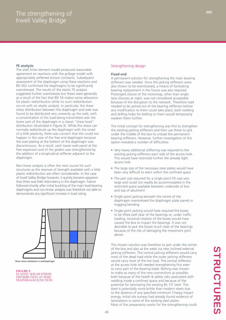
FE analysisThe shell finite element model produced reasonable agreement on reactions with the grillage model with appropriately softened torsion constants. Subsequent assessment of the diaphragm using these reactions and BD 562 confirmed the diaphragms to be significantly overstressed. The results of the elastic FE analysis suggested further overstresses but these were generally as a result of the fact that BD 56 makes some allowance for plastic redistribution while no such redistribution occurs with an elastic analysis. In particular, the shear stress distribution between the diaphragm and web was found to be distributed very unevenly up the web, with a concentration of the load being transmitted over the lower part of the diaphragm in a classic “shear boot” distribution (illustrated in Figure 9). While this shear can normally redistribute up the diaphragm with the onset of a little plasticity, there was concern that this could not happen in the case of the free end diaphragm because the over-plating at the bottom of the diaphragm was discontinuous. As a result, each lower web panel at the free expansion end of the girders was strengthened by the addition of a longitudinal stiffener adjacent to the diaphragm.
Non-linear analysis is often the next course for such structures as the reserves of strength available with a little plastic redistribution are often considerable. In the case of Irwell Valley Bridge however, it quickly became apparent that there was little redundancy in the diaphragm. Failure followed shortly after initial buckling of the main load bearing diaphragms and non-linear analysis was therefore not able to demonstrate any significant increase in load rating.
Figure 9eLastic shear stress distribution at web/diaphragm junction
Strengthening design
Fixed endA permanent solution for strengthening the main bearing stiffeners was needed. Since the jacking stiffeners were also shown to be overstressed, a means of facilitating bearing replacement in the future was also required. Prolonged closure of the motorway, other than single lane closures at night, was not considered acceptable because of the disruption to the network. Therefore load needed to be jacked out of the bearing stiffeners before any modification to them could take place; both welding and drilling holes for bolting to them would temporarily weaken them further.
The initial concept for strengthening was first to strengthen the existing jacking stiffeners and then use these to jack under the middle of the box to unload the permanent bearing stiffeners. However, further investigation of this option revealed a number of difficulties:
Very heavy additional stiffening was required to the • existing jacking stiffeners each side of the access hole. This would have restricted further the already tight access hole
The large size of the necessary steel plates would have • been very difficult to erect within the confined space
The jack size required for a single point lift was very • large and could not readily be accommodated in the restricted space available between underside of box and top of abutment
Single point jacking beneath the centre of the • diaphragm overstressed the diaphragm plate panels in hogging bending
Single point jacking would have required the boxes • to be lifted well clear of the bearings or, under traffic loading, torsional rotation of the boxes would have caused the box to impact the bearings. It was not desirable to jack the boxes much clear of the bearings because of the risk of damaging the movement joint above.
The chosen solution was therefore to jack under the centre of the box and also at the webs via new inclined external jacking stiffeners. The central jacking stiffeners would carry most of the dead load while the outer jacking stiffeners would carry most of the live load. The central stiffeners at the access hole still needed strengthening first even to carry part of the bearing loads. Bolting was chosen to make as many of the new connections as possible, both because of the health & safety risks associated with welding inside a confined space and because of the potential for laminating the existing BS 158 steel. This steel is potentially more brittle than modern steels due to the absence of any specified minimum Charpy impact energy. Initial site surveys had already found evidence of laminations in some of the existing steel plates. Most of the preparatory works for the strengthening could
The strengthening of Irwell Valley Bridge
005
46STR
UC
TUR
ES
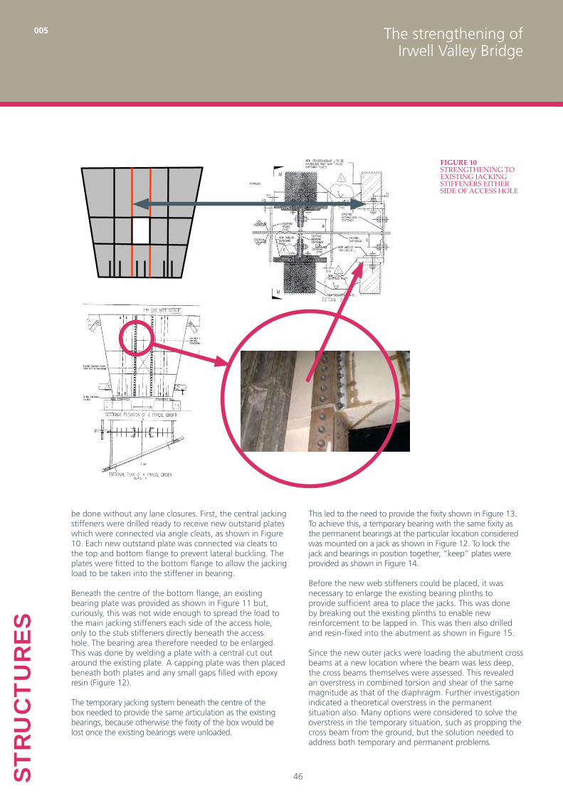
be done without any lane closures. First, the central jacking stiffeners were drilled ready to receive new outstand plates which were connected via angle cleats, as shown in Figure 10. Each new outstand plate was connected via cleats to the top and bottom flange to prevent lateral buckling. The plates were fitted to the bottom flange to allow the jacking load to be taken into the stiffener in bearing.
Beneath the centre of the bottom flange, an existing bearing plate was provided as shown in Figure 11 but, curiously, this was not wide enough to spread the load to the main jacking stiffeners each side of the access hole, only to the stub stiffeners directly beneath the access hole. The bearing area therefore needed to be enlarged. This was done by welding a plate with a central cut out around the existing plate. A capping plate was then placed beneath both plates and any small gaps filled with epoxy resin (Figure 12).
The temporary jacking system beneath the centre of the box needed to provide the same articulation as the existing bearings, because otherwise the fixity of the box would be lost once the existing bearings were unloaded.
Figure 10strengthening to existing jacking stiffeners either side of access hoLe
This led to the need to provide the fixity shown in Figure 13. To achieve this, a temporary bearing with the same fixity as the permanent bearings at the particular location considered was mounted on a jack as shown in Figure 12. To lock the jack and bearings in position together, “keep” plates were provided as shown in Figure 14.
Before the new web stiffeners could be placed, it was necessary to enlarge the existing bearing plinths to provide sufficient area to place the jacks. This was done by breaking out the existing plinths to enable new reinforcement to be lapped in. This was then also drilled and resin-fixed into the abutment as shown in Figure 15.
Since the new outer jacks were loading the abutment cross beams at a new location where the beam was less deep, the cross beams themselves were assessed. This revealed an overstress in combined torsion and shear of the same magnitude as that of the diaphragm. Further investigation indicated a theoretical overstress in the permanent situation also. Many options were considered to solve the overstress in the temporary situation, such as propping the cross beam from the ground, but the solution needed to address both temporary and permanent problems.

The strengthening of Irwell Valley Bridge
005
47
STRU
CTU
RES
The final solution was therefore to locally extend the cross beam soffit down to provide adequate resistance as shown in Figure 16. Reinforcement was drilled into the abutment wall and cross beam using automated mechanical drilling equipment to eliminate the risk of hand vibration injury. The drilled-in reinforcement was detailed to supplement the shear and torsion resistance of the existing cross beam. Anchorage lengths were determined using a draft HA Interim Advice Note9.
Once the central jacking stiffeners had been strengthened and the bearing plinths had been widened, a nominal load of 1000 kN was applied to the central jack to relieve some load from the permanent bearing stiffeners. This additional redundant support allowed the temporary props and the temporary stools to be removed. The props needed to be removed at this stage to get access to the area where the new web stiffeners were to be attached. The end cross bracing was also removed permanently at this stage. It was not required structurally but its presence attracted forces which structural assessment indicated it could not carry. This was evident by visible bowing in some of the bracing members.
After the central jack preload was applied and locked off, the webs were drilled to receive the bolts to attach the new outer web box stiffeners as shown in Figure 17(a). The stiffener bolt holes for attachments were kept behind the diaphragm to avoid reducing the web shear resistance; the webs were already highly stressed.
The new web stiffeners were fabricated box sections comprising a channel section with a bolted closing flange plate. These were constructed in weathering steel so that the inaccessible internal surfaces of the box stiffener need not be painted or be made overly thick to make allowance for corrosion. First the fabricated channel was bolted up to the web as shown in Figure 17(b). The channel had a welded top plate already fixed for subsequent connection to the box top flange to give transverse restraint. Then the bottom base plate was welded to the channel section
Figure 11existing bearing pLate beneath bottom fLange
Figure 12centraL jacking arrangement
Figure 13deck articuLation
Figure 14“keep” pLates to hoLd jack in position and fix bearing to jack

The strengthening of Irwell Valley Bridge
005
48STR
UC
TUR
ES
Figure 15extension of bearing pLinths
Figure 16strengthening to substructure
and the bottom flange of the box to provide transverse restraint to the stiffener and a defined flat bearing area, and the outer flange plate was bolted to the channel section via cleats – Figure 17(c). Finally, the top flange plate was welded to the top flange of the box, again to provide transverse restraint.
The design of the outer web jacking stiffeners was outside the scope of BS 5400:Part 36 because they were both single sided (and thus eccentric to the web) and also not vertical. Both of these unusual aspects gave rise to special design considerations:
(1) Single sided stiffenerThe distribution of moment up the stiffener depends on how the shear is carried up the height of the stiffener. If the shear is carried uniformly up the height of the stiffener and the load acts at the centroid of the stiffener effective section (including attached web plate), no moment is produced in the stiffener as shown in Figure 18 (a). Any eccentricity from the centroid causes moments as in a normal symmetrical stiffener as shown in Figure 18 (b). However, if the shear is carried non-uniformly up the height of the stiffener (with more shear carried in the lower portion of the diaphragm) and the load acts at effective section centroid, some moment is developed as shown in Figure 18 (c). Variations in distribution of shear up the web do not normally give rise to stiffener moments where the stiffeners are symmetrical about the web. Any eccentricity from the effective section centroid causes additional moments as in a normal symmetrical stiffener as shown in Figure 18 (d). Allowance was therefore made for uneven shear distribution up the web in design. This was compared with the design stresses based on the results of finite element analysis, which gave results similar to that shown in Figure 18 (d).
(2) Non-vertical stiffener The non-verticality of the stiffeners leads to transverse compression in the bottom flange of the box which then needed to be checked for buckling. This check was easily accommodated because the bottom flange was relatively thick and the width of the flange plate transversely between diaphragm and end cover plate was small.
After the installation of the web jacking stiffeners and the central diaphragm stiffeners, the box was jacked under night-time lane closures. Lane closures were necessary to permit accurate monitoring of the jacking loads against anticipated dead loads. The central jack was loaded to 2500 kN first. The jack was then floated at this load and the outer jacks were incrementally loaded until both permanent bearing loads were reduced to zero. Lift off at the bearings was determined from load deflection plots and the outer jack loads were limited to a maximum of 500 kN, which was not exceeded. All three jacks were then locked off. The outer bearing stiffeners subsequently carried the majority of the live load when the lane closures were taken off and the central stiffeners carried only a small part of the live load.

The strengthening of Irwell Valley Bridge
005
49
STRU
CTU
RES
Figure 17attachment of outer box jacking stiffeners
(a) (b) (c)
Figure 18distribution of moment in web jacking stiffeners for different eccentricities and shear distributions up the web
PΔ/H
Δ
P (at centroid)
PΔ/H
P H
PΔ/H
Δ
P (eccentric) Moment PΔ/H
P H
Δ
P (at centroid) No moment
PΔ/H
PΔ/H
P
H
Δ
P (eccentric) Moment
PΔ/H
PΔ/H
P
H
(a) (b)
(c) (d)
(a) (b)
(c) (d)

The strengthening of Irwell Valley Bridge
005
50STR
UC
TUR
ES
After the jacks were locked off, installation of the strengthening to the permanent bearing stiffeners could begin, as shown in Figure 19. It was necessary first to over-run the welds between the diaphragm and the flange and the stub stiffeners in order to give adequate fatigue performance. Holes were first drilled through the existing stiffeners to receive angle cleats and then the main stiffener flange plates were added by bolting to the cleats.
The top and bottom of each stiffener flange plate was also cleated to the top and bottom box flanges respectively to give transverse restraint. This was necessary because the stiffener flange plates were not welded to the bottom flange; it was not physically possible and large welds would have been undesirable. Instead, the stiffeners were closely fitted and all bearing loads were carried into the stiffener in bearing.
3.2.2 Free end strengthening sequenceThe free end strengthening followed a very similar sequence and detailing but welding of stiffeners was needed in places due to the presence of previous strengthening in the 1980s which restricted the access for bolting. Welding needed to be carefully controlled, particularly for connecting web stiffeners, because the heat weakens the metal in the web and reduces the shear strength and stiffness. To minimise this effect, it was required for welding to be carried out in such a way that the height of web material experiencing a temperature increase in excess of 200˚ at any instant be less than 500 mm. The reduction in strength and stiffness associated with this temperature was determined in accordance with EN 1993-1-210. Weld procedure trials were carried out to confirm this was possible and also to ensure that the electrodes were matched to the BS 158 steel.
3.2.3 Construction sequence for all boxesFor programme reasons, more than one box needed to be worked on at any one time. The system of replacing the permanent bearing restraints with equivalent temporary ones permitted all boxes to be worked on and jacked at the same time. Lane closures on the M60 motorway were required for any welding and jacking but these were limited to overnight closures only; the client (Highways Agency) placed great value on minimising network disruption. These lane closures could only be implemented between 9pm and 5am, including time for installation and removal of the Traffic Management system and the cooling of the welds. Effective programme management was therefore essential to the successful delivery of the scheme.
Figure 19finaL strengthening arrangement
The strengthening of Irwell Valley Bridge
005
51
STRU
CTU
RES
5. Acknowledgements
This paper is published with the permission of the Highways Agency and John Martin Construction. The authors would also like to acknowledge Gary Knowles, Atkins Area 10 Project Manager, for his effective coordination of the numerous parties while the strengthening work was being procured and on site.
4. Virtual Reality Model
The Designer’s Risk Assessment identified a number of hazards in the design which were combated at source. These included welding in the confined space (bolting was generally used) and handling of excessively heavy steel plates (steelwork was split into smaller components). However, the complex construction sequence itself was highlighted as a significant risk because execution of certain activities in the wrong sequence had potentially very severe consequences. By way of mitigation, it was decided that a virtual reality (VR) model should be prepared. This would allow visualisation of the strengthening process and a means of stepping through the stages of construction in the correct sequence.
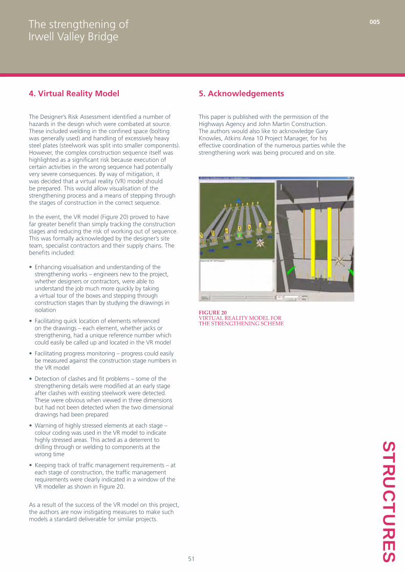
In the event, the VR model (Figure 20) proved to have far greater benefit than simply tracking the construction stages and reducing the risk of working out of sequence. This was formally acknowledged by the designer’s site team, specialist contractors and their supply chains. The benefits included:
Enhancing visualisation and understanding of the • strengthening works – engineers new to the project, whether designers or contractors, were able to understand the job much more quickly by taking a virtual tour of the boxes and stepping through construction stages than by studying the drawings in isolation
Facilitating quick location of elements referenced • on the drawings – each element, whether jacks or strengthening, had a unique reference number which could easily be called up and located in the VR model
Facilitating progress monitoring – progress could easily • be measured against the construction stage numbers in the VR model
Detection of clashes and fit problems – some of the • strengthening details were modified at an early stage after clashes with existing steelwork were detected. These were obvious when viewed in three dimensions but had not been detected when the two dimensional drawings had been prepared
Warning of highly stressed elements at each stage – • colour coding was used in the VR model to indicate highly stressed areas. This acted as a deterrent to drilling through or welding to components at the wrong time
Keeping track of traffic management requirements – at • each stage of construction, the traffic management requirements were clearly indicated in a window of the VR modeller as shown in Figure 20.
As a result of the success of the VR model on this project, the authors are now instigating measures to make such models a standard deliverable for similar projects.
Figure 20VirtuaL reaLity modeL for the strengthening scheme

The strengthening of Irwell Valley Bridge
005
52STR
UC
TUR
ES
References
1. DEPARTMENT OF THE ENVIORNMENT (MERRISON COMMITTEE OF INQUIRY). Inquiry into the Basis of Design and Method of Erection of Steel Box Girder Bridges – Appendix 1: Interim Design and Workmanship Rules. HMSO, 1973
2. HIGHWAYS AGENCY. Design Manual for Roads and Bridges, BD56 – The Assessment of Steel Highway Bridges and Structures. Highways Agency, London, 1996
3. HIGHWAYS AGENCY. Design Manual for Roads and Bridges, BD61 – The Assessment of Composite Highway Bridges and Structures. Highways Agency, London, 1996
4. MOFFAT, K. R., DOWLING, P. J. The longitudinal bending behaviour of composite box girder bridges having incomplete interaction. Structural Engineer, 56B, No. 3, 53–60, 1978
5. HENDY, C.R., JOHNSON, R.P. Designers’ Guide to EN 1994-2, Steel and Concrete Composite Bridges. Thomas Telford, London, 2006
6. BRITISH STANDARDS INSTITUTION. Steel, Concrete and Composite Bridges, Part 3 – Code of Practice for Design of Steel Bridges. BSI, London, 2000, BS 5400
7. ILES, D. C. Design guide for composite box girder bridges. Steel Construction Institute, Ascot, 1994
8. BRITISH STANDARDS INSTITUTION. Mild Steel for general structural purposes. BSI, London, 1961, BS15
9. HIGHWAYS AGENCY. Design Manual for Roads and Bridges – Draft Interim Advice Note – The anchorage of reinforcement and fixings in hardened concrete. Unpublished (2005).
10. EUROPEAN COMMITTEE FOR STANDARDISATION. Eurocode 3: Design of Steel Structures – Part 1-2: General Rules – Structural Fire Design. CEN, Brussels, 2005, EN 1993-1-2