structural masonry analysis: recent developments and prospects · 2015-03-22 · structural masonry...
TRANSCRIPT
STRUCTURAL MASONRY ANALYSIS: RECENT DEVELOPMENTS AND PROSPECTS
PAULO B. LOURENÇO1
1Professor ISISE, University of Minho, Department of Civil Engineering, Portugal
E-mail: [email protected]
SUMMARY The mechanics of masonry structures has been underdeveloped in comparison with other fields of knowledge, with non-linear analysis being a popular field in research. Here, the possibilities of using structural component models and detailed models using macro-modelling and micro-modelling are addressed. The possibility of linking micro- and macro-approaches through homogenization techniques is highlighted. Finally, recommendations for material data required for advanced non-linear analysis are provided.
INTRODUCTION
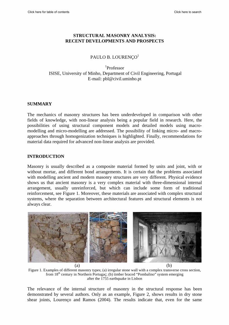
Masonry is usually described as a composite material formed by units and joint, with or without mortar, and different bond arrangements. It is certain that the problems associated with modelling ancient and modern masonry structures are very different. Physical evidence shows us that ancient masonry is a very complex material with three-dimensional internal arrangement, usually unreinforced, but which can include some form of traditional reinforcement, see Figure 1. Moreover, these materials are associated with complex structural systems, where the separation between architectural features and structural elements is not always clear.
(a) (b) Figure 1. Examples of different masonry types; (a) irregular stone wall with a complex transverse cross section,
from 18th century in Northern Portugaç; (b) timber braced “Pombalino” system emerging after the 1755 earthquake in Lisbon
The relevance of the internal structure of masonry in the structural response has been demonstrated by several authors. Only as an example, Figure 2, shows results in dry stone shear joints, Lourenço and Ramos (2004). The results indicate that, even for the same
Click here to searchClick here for table of contents
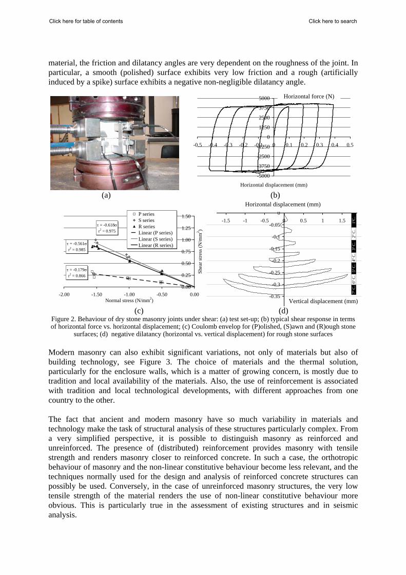
material, the friction and dilatancy angles are very dependent on the roughness of the joint. In particular, a smooth (polished) surface exhibits very low friction and a rough (artificially induced by a spike) surface exhibits a negative non-negligible dilatancy angle.
-5000
-3750
-2500
-1250
0
1250
2500
3750
5000
-0.5 -0.4 -0.3 -0.2 -0.1 0 0.1 0.2 0.3 0.4 0.5
Horizontal displacement (mm) (a) (b)
τ = -0.179σr2 = 0.866
τ = -0.618σr2 = 0.975
τ = -0.561σr2 = 0.985
0.00
0.25
0.50
0.75
1.00
1.25
1.50
-2.00 -1.50 -1.00 -0.50 0.00Normal stress (N/mm2)
Shea
r stre
ss (N
/mm
2 )
P seriesS seriesR seriesLinear (P series)Linear (S series)Linear (R series)
(c) (d) Figure 2. Behaviour of dry stone masonry joints under shear: (a) test set-up; (b) typical shear response in terms of horizontal force vs. horizontal displacement; (c) Coulomb envelop for (P)olished, (S)awn and (R)ough stone
surfaces; (d) negative dilatancy (horizontal vs. vertical displacement) for rough stone surfaces Modern masonry can also exhibit significant variations, not only of materials but also of building technology, see Figure 3. The choice of materials and the thermal solution, particularly for the enclosure walls, which is a matter of growing concern, is mostly due to tradition and local availability of the materials. Also, the use of reinforcement is associated with tradition and local technological developments, with different approaches from one country to the other. The fact that ancient and modern masonry have so much variability in materials and technology make the task of structural analysis of these structures particularly complex. From a very simplified perspective, it is possible to distinguish masonry as reinforced and unreinforced. The presence of (distributed) reinforcement provides masonry with tensile strength and renders masonry closer to reinforced concrete. In such a case, the orthotropic behaviour of masonry and the non-linear constitutive behaviour become less relevant, and the techniques normally used for the design and analysis of reinforced concrete structures can possibly be used. Conversely, in the case of unreinforced masonry structures, the very low tensile strength of the material renders the use of non-linear constitutive behaviour more obvious. This is particularly true in the assessment of existing structures and in seismic analysis.
-0.35
-0.3
-0.25
-0.2
-0.15
-0.1
-0.05
0-1.5 -1 -0.5 0 0.5 1 1.5 1º
C.
2º C
.3º
C.
4º C
.5º
C.
6º C
.7º
C.
Horizontal force (N)
Vertical displacement (mm)
Horizontal displacement (mm)
Click here to searchClick here for table of contents

(a)
(b)
(c)
Figure 3. Examples of modern masonry: (a) typical European unreinforced masonry used in areas of low seismicity using thick blocks to comply with thermal and sound regulations;
(b) confined masonry in areas of moderate to high seismicity, again with thick blocks; (c) different reinforced masonry solutions, adopted in the US, Italy and Switzerland, respectively
MODELLING POSSIBILITIES FOR MASONRY STRUCTURES
Masonry is also usually described as a material exhibiting distinct directional properties due to the mortar joints, which act as planes of weakness. This description is associated mostly with the material, whereas a different description can be given at structural level. These descriptions are briefly reviewed below.
Description at material level
In general, the approach towards the numerical representation of masonry can address the micro modelling of the individual components, viz. unit (brick, block, etc.) and mortar, or the macro modelling of masonry as a composite, Rots (1991). Depending on the level of accuracy
Click here to searchClick here for table of contents
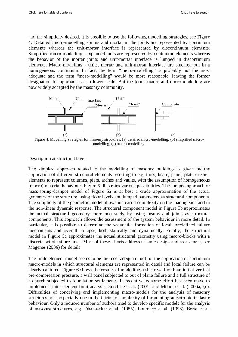
and the simplicity desired, it is possible to use the following modelling strategies, see Figure 4: Detailed micro-modelling - units and mortar in the joints are represented by continuum elements whereas the unit-mortar interface is represented by discontinuum elements; Simplified micro-modelling - expanded units are represented by continuum elements whereas the behavior of the mortar joints and unit-mortar interface is lumped in discontinuum elements; Macro-modelling - units, mortar and unit-mortar interface are smeared out in a homogeneous continuum. In fact, the term “micro-modelling” is probably not the most adequate and the term “meso-modelling” would be more reasonable, leaving the former designation for approaches at a lower scale. But the terms macro and micro-modelling are now widely accepted by the masonry community.
Mortar Unit Interface Unit/Mortar
“Unit”“Joint” Composite
(a) (b) (c)
Figure 4. Modelling strategies for masonry structures: (a) detailed micro-modelling; (b) simplified micro-modelling; (c) macro-modelling.
Description at structural level
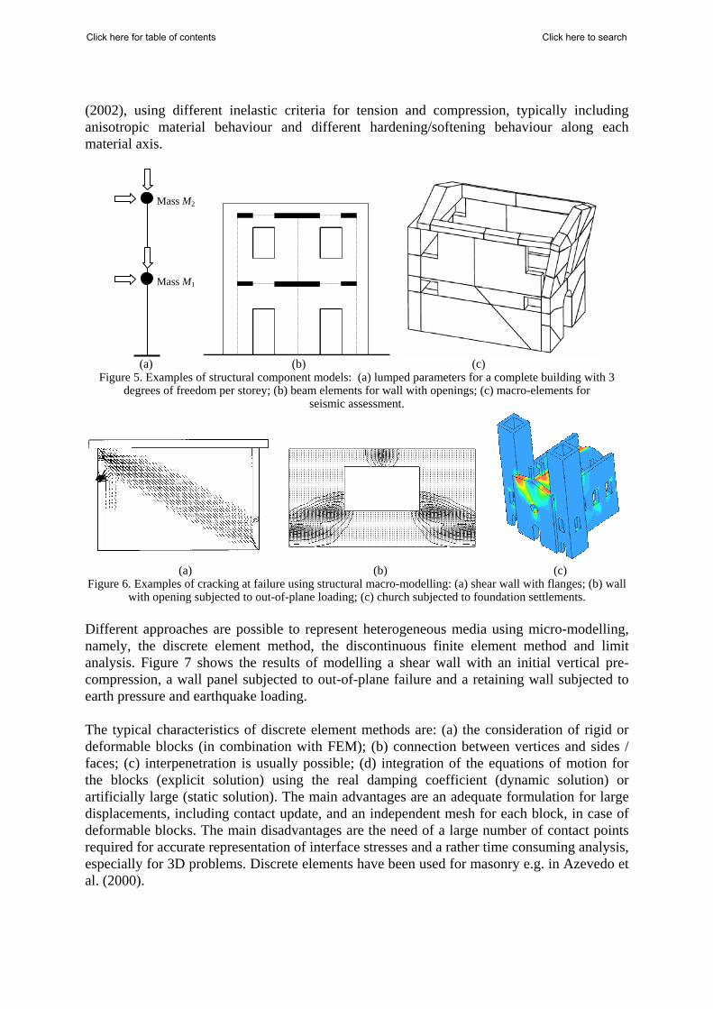
The simplest approach related to the modelling of masonry buildings is given by the application of different structural elements resorting to e.g. truss, beam, panel, plate or shell elements to represent columns, piers, arches and vaults, with the assumption of homogeneous (macro) material behaviour. Figure 5 illustrates various possibilities. The lumped approach or mass-spring-dashpot model of Figure 5a is at best a crude approximation of the actual geometry of the structure, using floor levels and lumped parameters as structural components. The simplicity of the geometric model allows increased complexity on the loading side and in the non-linear dynamic response. The structural component model in Figure 5b approximates the actual structural geometry more accurately by using beams and joints as structural components. This approach allows the assessment of the system behaviour in more detail. In particular, it is possible to determine the sequential formation of local, predefined failure mechanisms and overall collapse, both statically and dynamically. Finally, the structural model in Figure 5c approximates the actual structural geometry using macro-blocks with a discrete set of failure lines. Most of these efforts address seismic design and assessment, see Magenes (2006) for details. The finite element model seems to be the most adequate tool for the application of continuum macro-models in which structural elements are represented in detail and local failure can be clearly captured. Figure 6 shows the results of modelling a shear wall with an initial vertical pre-compression pressure, a wall panel subjected to out of plane failure and a full structure of a church subjected to foundation settlements. In recent years some effort has been made to implement finite element limit analysis, Sutcliffe et al. (2001) and Milani et al. (2006a,b,c). Difficulties of conceiving and implementing macro-models for the analysis of masonry structures arise especially due to the intrinsic complexity of formulating anisotropic inelastic behaviour. Only a reduced number of authors tried to develop specific models for the analysis of masonry structures, e.g. Dhanasekar et al. (1985), Lourenço et al. (1998), Berto et al.
Click here to searchClick here for table of contents
(2002), using different inelastic criteria for tension and compression, typically including anisotropic material behaviour and different hardening/softening behaviour along each material axis.
(a) (b) (c)
Figure 5. Examples of structural component models: (a) lumped parameters for a complete building with 3 degrees of freedom per storey; (b) beam elements for wall with openings; (c) macro-elements for
seismic assessment.
(a) (b) (c) Figure 6. Examples of cracking at failure using structural macro-modelling: (a) shear wall with flanges; (b) wall
with opening subjected to out-of-plane loading; (c) church subjected to foundation settlements. Different approaches are possible to represent heterogeneous media using micro-modelling, namely, the discrete element method, the discontinuous finite element method and limit analysis. Figure 7 shows the results of modelling a shear wall with an initial vertical pre-compression, a wall panel subjected to out-of-plane failure and a retaining wall subjected to earth pressure and earthquake loading. The typical characteristics of discrete element methods are: (a) the consideration of rigid or deformable blocks (in combination with FEM); (b) connection between vertices and sides / faces; (c) interpenetration is usually possible; (d) integration of the equations of motion for the blocks (explicit solution) using the real damping coefficient (dynamic solution) or artificially large (static solution). The main advantages are an adequate formulation for large displacements, including contact update, and an independent mesh for each block, in case of deformable blocks. The main disadvantages are the need of a large number of contact points required for accurate representation of interface stresses and a rather time consuming analysis, especially for 3D problems. Discrete elements have been used for masonry e.g. in Azevedo et al. (2000).
Mass M2
Mass M1
Click here to searchClick here for table of contents
(a) (b) (c) Figure 7. Examples of cracking at failure using structural micro-modelling: (a) shear wall with opening; (b) wall
subjected to out-of-plane loading; (c) retaining wall. The finite element method remains the most used tool for numerical analysis in solid mechanics and an extension from standard continuum finite elements to represent discrete joints was developed in the early days of non-linear mechanics, with an early application to masonry, Page (1978). On the contrary, limit analysis received far less attention from the technical and scientific community for masonry structures, even with also an early application in Livesley (1978). Still, limit analysis has the advantage of being a simple tool, while having the disadvantages that only the collapse load and the collapse mechanism can be obtained and the loading history can hardly be included. A complete micro-model must include all the failure mechanisms of masonry, namely, cracking of joints, sliding over one head or bed joint, cracking of the units and crushing of masonry, Lourenço and Rots (1997). By adopting appropriate evolution rules in a finite element environment, Oliveira and Lourenço (2004), it is possible to reproduce non-linear behaviour during unloading. Orduña and Lourenço (2005) developed a limit analysis constitutive model that incorporates non-associated flow at the joints, compressive failure and a novel formulation for torsion.
HOMOGENIZATION TECHNIQUES
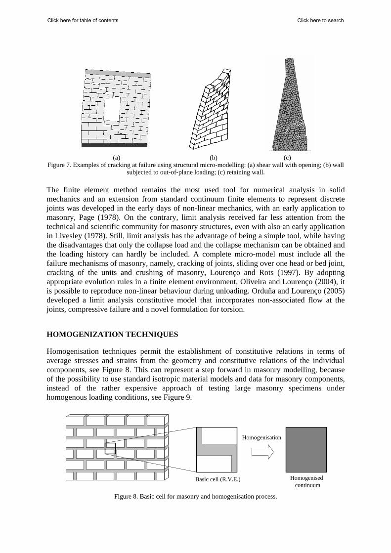
Homogenisation techniques permit the establishment of constitutive relations in terms of average stresses and strains from the geometry and constitutive relations of the individual components, see Figure 8. This can represent a step forward in masonry modelling, because of the possibility to use standard isotropic material models and data for masonry components, instead of the rather expensive approach of testing large masonry specimens under homogenous loading conditions, see Figure 9.
Figure 8. Basic cell for masonry and homogenisation process.
Basic cell (R.V.E.) Homogenised
continuum
Homogenisation
Click here to searchClick here for table of contents
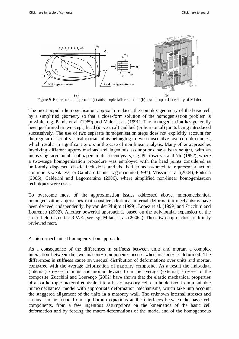
(a) (b)
Figure 9. Experimental approach: (a) anisotropic failure model; (b) test set-up at University of Minho. The most popular homogenisation approach replaces the complex geometry of the basic cell by a simplified geometry so that a close-form solution of the homogenisation problem is possible, e.g. Pande et al. (1989) and Maier et al. (1991). The homogenisation has generally been performed in two steps, head (or vertical) and bed (or horizontal) joints being introduced successively. The use of two separate homogenisation steps does not explicitly account for the regular offset of vertical mortar joints belonging to two consecutive layered unit courses, which results in significant errors in the case of non-linear analysis. Many other approaches involving different approximations and ingenious assumptions have been sought, with an increasing large number of papers in the recent years, e.g. Pietruszczak and Niu (1992), where a two-stage homogenization procedure was employed with the head joints considered as uniformly dispersed elastic inclusions and the bed joints assumed to represent a set of continuous weakness, or Gambarotta and Lagomarsino (1997), Massart et al. (2004), Podestà (2005), Calderini and Lagomarsino (2006), where simplified non-linear homogenisation techniques were used. To overcome most of the approximation issues addressed above, micromechanical homogenisation approaches that consider additional internal deformation mechanisms have been derived, independently, by van der Pluijm (1999), Lopez et al. (1999) and Zucchini and Lourenço (2002). Another powerful approach is based on the polynomial expansion of the stress field inside the R.V.E., see e.g. Milani et al. (2006a). These two approaches are briefly reviewed next.
A micro-mechanical homogenization approach
As a consequence of the differences in stiffness between units and mortar, a complex interaction between the two masonry components occurs when masonry is deformed. The differences in stiffness cause an unequal distribution of deformations over units and mortar, compared with the average deformation of masonry composite. As a result the individual (internal) stresses of units and mortar deviate from the average (external) stresses of the composite. Zucchini and Lourenço (2002) have shown that the elastic mechanical properties of an orthotropic material equivalent to a basic masonry cell can be derived from a suitable micromechanical model with appropriate deformation mechanisms, which take into account the staggered alignment of the units in a masonry wall. The unknown internal stresses and strains can be found from equilibrium equations at the interfaces between the basic cell components, from a few ingenious assumptions on the kinematics of the basic cell deformation and by forcing the macro-deformations of the model and of the homogeneous
Click here to searchClick here for table of contents
material to contain the same strain energy. This homogenisation model has already been extended with good results to non-linear problems in the case of a masonry cell failure under tensile loading parallel to the bed joint and under compressive loading, Zucchini and Lourenço (2004, 2006). The simulation has been accomplished by coupling the elastic micro-mechanical model with a damage model for joints and units by means of an iterative solution procedure to calculate the damage coefficients. A simple isotropic damage model with only one single parameter has been utilized, because the discrete internal structure of the cell, and implicitly its global anisotropic behaviour, is taken into account by the three-dimensional micromechanical model. When the basic cell is loaded only with normal stresses, the micromechanical model of Zucchini and Lourenço (2002) assumes that all shear stresses and strains inside the basic cell can be neglected, except the in-plane shear stress and strain (σxy and εxy) in the bed joint and in the unit. The non-zero stresses and strains in the bed joint, head joint and unit are assumed to be constant, with the exception of the normal stress σxx in the unit, which is a linear function of x and accounts for the effect of the shear σxy in the bed joint, and with the exception of the shear stress σxy in the unit, which is linear in y. The coupling of this model with non-linear constitutive models, leads to an iterative algorithm, in which at each cycle a system of equilibrium equations is solved to obtain the unknown effective stresses and strains. The model was applied to a real masonry basic cell and compared with the results of an accurate finite element analysis (FEA) under linear elastic analysis. In the finite element analysis and the analytical model, the properties of the components can be taken absolutely equal. Different stiffness ratios between mortar and unit are considered. The material properties of the unit are kept constant, whereas the properties of the mortar are varied to yield a ratio Eb / Em ranging from 1 to 1000. The adopted range is very large, if only linear elastic behaviour of mortar is considered. However, those high values are indeed encountered if inelastic behaviour is included. In such case, Eb and Em should be understood as linearised tangent Young’s moduli, representing a measure of the degradation of the (tangent / secant) stiffness matrices utilised in the numerical procedures adopted to solve the non-linear problem. Note that the ratio Eb / Em tends to infinity when softening of the mortar is complete and only the unit remains structurally active. The elastic properties of the homogenised material, calculated by means of the proposed micro-mechanical model, are compared in Figure 10a with the values obtained by FE analysis. The agreement is very good in the entire range 1≤ Eb / Em ≤1000, with a maximum error ≤ 6%. A comparison between the results obtained with the micro-mechanical model and the experimental results of Page (1981,1983) are given in Figure 10b. Very good agreement is found in the shape of the yield surface, indicating that the proposed model can be used as a possible macro-model to represent the composite failure of masonry. Figure 11 shows the validation of the model under non-linear uniaxial loading. The algorithm has been tested in the fracture problem of an infinitely long wall under tensile loading parallel to the bed joint (Figure 11a), which has been analysed by Lourenco et al. (1999) with a sophisticated finite element interface model based on multisurface plasticity. The model reproduces with good agreement the FE analysis of the cell degradation and the two peaks of the failure load for a zero dilatancy angle in the joints. The head joint is the first to fail in tension and the bed joint takes its place in the load carrying mechanism of the cell. The load is transferred through bed joint shear from unit to the other, with the cell showing regained elastic behaviour for increasing loads, until final failure of the bed joint in shear. The residual
Click here to searchClick here for table of contents
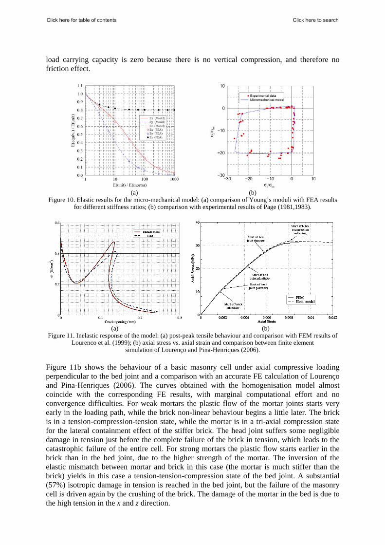
load carrying capacity is zero because there is no vertical compression, and therefore no friction effect.
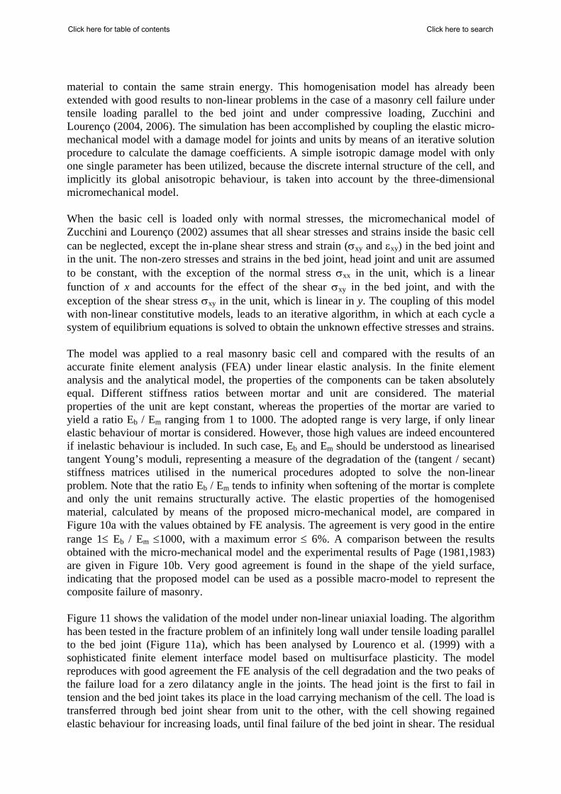
(a) (b) Figure 10. Elastic results for the micro-mechanical model: (a) comparison of Young’s moduli with FEA results
for different stiffness ratios; (b) comparison with experimental results of Page (1981,1983).
(a) (b) Figure 11. Inelastic response of the model: (a) post-peak tensile behaviour and comparison with FEM results of
Lourenco et al. (1999); (b) axial stress vs. axial strain and comparison between finite element simulation of Lourenço and Pina-Henriques (2006).
Figure 11b shows the behaviour of a basic masonry cell under axial compressive loading perpendicular to the bed joint and a comparison with an accurate FE calculation of Lourenço and Pina-Henriques (2006). The curves obtained with the homogenisation model almost coincide with the corresponding FE results, with marginal computational effort and no convergence difficulties. For weak mortars the plastic flow of the mortar joints starts very early in the loading path, while the brick non-linear behaviour begins a little later. The brick is in a tension-compression-tension state, while the mortar is in a tri-axial compression state for the lateral containment effect of the stiffer brick. The head joint suffers some negligible damage in tension just before the complete failure of the brick in tension, which leads to the catastrophic failure of the entire cell. For strong mortars the plastic flow starts earlier in the brick than in the bed joint, due to the higher strength of the mortar. The inversion of the elastic mismatch between mortar and brick in this case (the mortar is much stiffer than the brick) yields in this case a tension-tension-compression state of the bed joint. A substantial (57%) isotropic damage in tension is reached in the bed joint, but the failure of the masonry cell is driven again by the crushing of the brick. The damage of the mortar in the bed is due to the high tension in the x and z direction.
Click here to searchClick here for table of contents
A stress field expansion approach
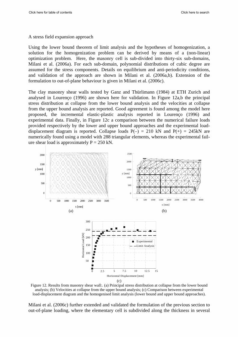
Using the lower bound theorem of limit analysis and the hypotheses of homogenization, a solution for the homogenization problem can be derived by means of a (non-linear) optimization problem. Here, the masonry cell is sub-divided into thirty-six sub-domains, Milani et al. (2006a). For each sub-domain, polynomial distributions of cubic degree are assumed for the stress components. Details on equilibrium and anti-periodicity conditions, and validation of the approach are shown in Milani et al. (2006a,b). Extension of the formulation to out-of-plane behaviour is given in Milani et al. (2006c). The clay masonry shear walls tested by Ganz and Thürlimann (1984) at ETH Zurich and analysed in Lourenço (1996) are shown here for validation. In Figure 12a,b the principal stress distribution at collapse from the lower bound analysis and the velocities at collapse from the upper bound analysis are reported. Good agreement is found among the model here proposed, the incremental elastic-plastic analysis reported in Lourenço (1996) and experimental data. Finally, in Figure 12c a comparison between the numerical failure loads provided respectively by the lower and upper bound approaches and the experimental load-displacement diagram is reported. Collapse loads P(–) = 210 kN and P(+) = 245kN are numerically found using a model with 288 triangular elements, whereas the experimental fail-ure shear load is approximately P = 250 kN.
0 500 1000 1500 2000 2500 3000 3500
0
500
1000
1500
2000
x [mm]
y [mm]
0 500 1000 1500 2000 2500 3000 3500 4000
0
500
1000
1500
2000
2500
x [mm]
y [mm]
(a) (b)
0 2.5 5 7.5 10 12.5 15
Horizontal Displacement [mm]
50
100
150
200
250
300
Hor
izon
tal L
oad
[kN
]
ExperimentalLimit Analysis
(c)
Figure 12. Results from masonry shear wall:. (a) Principal stress distribution at collapse from the lower bound analysis; (b) Velocities at collapse from the upper bound analysis; (c) Comparison between experimental
load-displacement diagram and the homogenised limit analysis (lower bound and upper bound approaches). Milani et al. (2006c) further extended and validated the formulation of the previous section to out-of-plane loading, where the elementary cell is subdivided along the thickness in several
Click here to searchClick here for table of contents
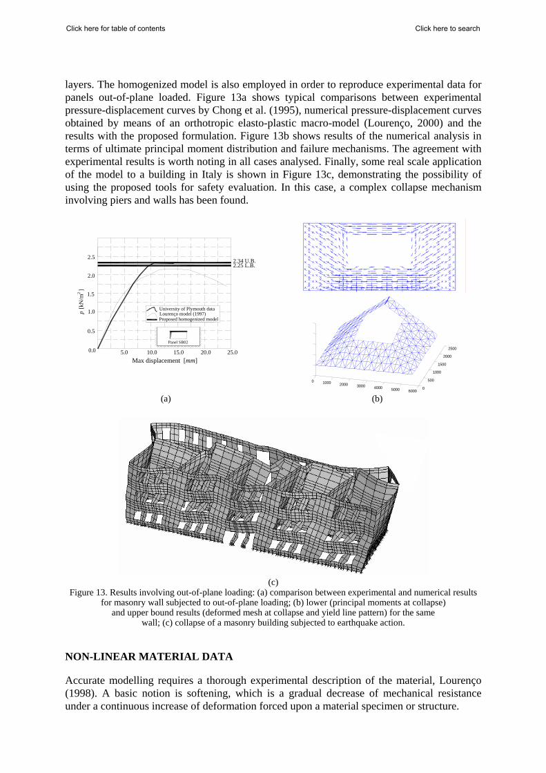
layers. The homogenized model is also employed in order to reproduce experimental data for panels out-of-plane loaded. Figure 13a shows typical comparisons between experimental pressure-displacement curves by Chong et al. (1995), numerical pressure-displacement curves obtained by means of an orthotropic elasto-plastic macro-model (Lourenço, 2000) and the results with the proposed formulation. Figure 13b shows results of the numerical analysis in terms of ultimate principal moment distribution and failure mechanisms. The agreement with experimental results is worth noting in all cases analysed. Finally, some real scale application of the model to a building in Italy is shown in Figure 13c, demonstrating the possibility of using the proposed tools for safety evaluation. In this case, a complex collapse mechanism involving piers and walls has been found.
20.0 25.00.0 5.0 10.0 15.0
p [k
N/m
]2
2.0
1.0
2.5
1.5
0.5
2.34 U.B.2.25 L.B.
Panel SB02
University of Plymouth dataLourenço model (1997)Proposed homogenized model
Max displacement [mm]
0 1000 2000 3000 4000 5000 60000
500
1000
1500
2000
2500
(a) (b)
(c)
Figure 13. Results involving out-of-plane loading: (a) comparison between experimental and numerical results for masonry wall subjected to out-of-plane loading; (b) lower (principal moments at collapse)
and upper bound results (deformed mesh at collapse and yield line pattern) for the same wall; (c) collapse of a masonry building subjected to earthquake action.
NON-LINEAR MATERIAL DATA
Accurate modelling requires a thorough experimental description of the material, Lourenço (1998). A basic notion is softening, which is a gradual decrease of mechanical resistance under a continuous increase of deformation forced upon a material specimen or structure.
Click here to searchClick here for table of contents
Non-linear properties of unit and mortar (tension)
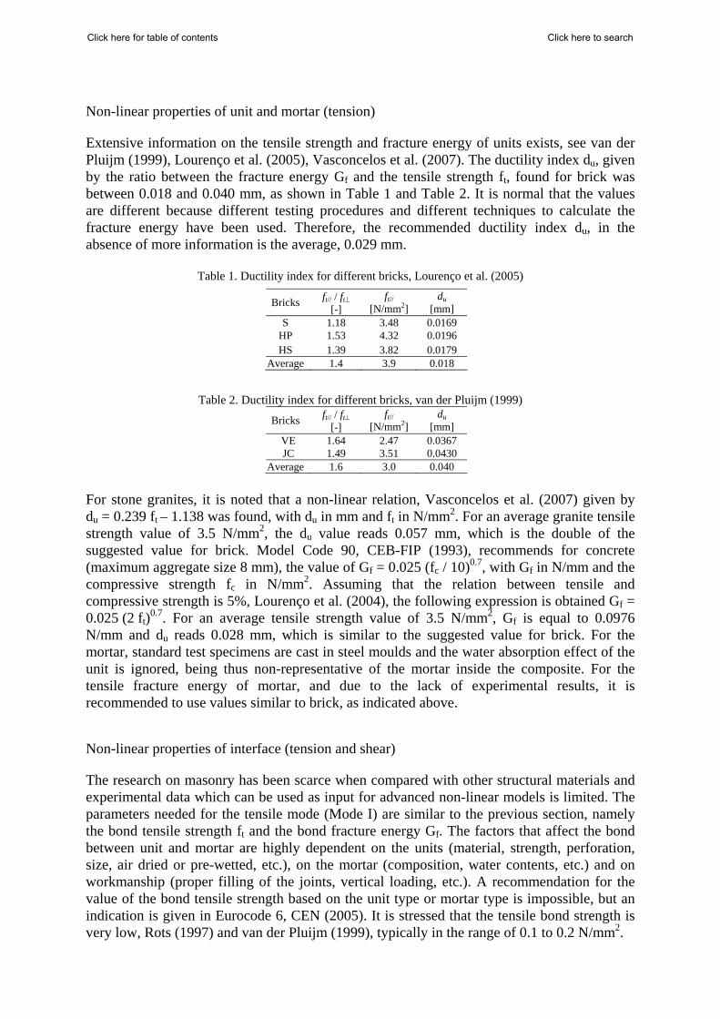
Extensive information on the tensile strength and fracture energy of units exists, see van der Pluijm (1999), Lourenço et al. (2005), Vasconcelos et al. (2007). The ductility index du, given by the ratio between the fracture energy Gf and the tensile strength ft, found for brick was between 0.018 and 0.040 mm, as shown in Table 1 and Table 2. It is normal that the values are different because different testing procedures and different techniques to calculate the fracture energy have been used. Therefore, the recommended ductility index du, in the absence of more information is the average, 0.029 mm.
Table 1. Ductility index for different bricks, Lourenço et al. (2005)
Bricks ft// / ft⊥ [-]
ft// [N/mm2]
du [mm]
S 1.18 3.48 0.0169 HP 1.53 4.32 0.0196 HS 1.39 3.82 0.0179
Average 1.4 3.9 0.018
Table 2. Ductility index for different bricks, van der Pluijm (1999)
Bricks ft// / ft⊥ [-]
ft// [N/mm2]
du [mm]
VE 1.64 2.47 0.0367 JC 1.49 3.51 0.0430
Average 1.6 3.0 0.040 For stone granites, it is noted that a non-linear relation, Vasconcelos et al. (2007) given by du = 0.239 ft – 1.138 was found, with du in mm and ft in N/mm2. For an average granite tensile strength value of 3.5 N/mm2, the du value reads 0.057 mm, which is the double of the suggested value for brick. Model Code 90, CEB-FIP (1993), recommends for concrete (maximum aggregate size 8 mm), the value of Gf = 0.025 (fc / 10)0.7, with Gf in N/mm and the compressive strength fc in N/mm2. Assuming that the relation between tensile and compressive strength is 5%, Lourenço et al. (2004), the following expression is obtained Gf = 0.025 (2 ft)0.7. For an average tensile strength value of 3.5 N/mm2, Gf is equal to 0.0976 N/mm and du reads 0.028 mm, which is similar to the suggested value for brick. For the mortar, standard test specimens are cast in steel moulds and the water absorption effect of the unit is ignored, being thus non-representative of the mortar inside the composite. For the tensile fracture energy of mortar, and due to the lack of experimental results, it is recommended to use values similar to brick, as indicated above.
Non-linear properties of interface (tension and shear)
The research on masonry has been scarce when compared with other structural materials and experimental data which can be used as input for advanced non-linear models is limited. The parameters needed for the tensile mode (Mode I) are similar to the previous section, namely the bond tensile strength ft and the bond fracture energy Gf. The factors that affect the bond between unit and mortar are highly dependent on the units (material, strength, perforation, size, air dried or pre-wetted, etc.), on the mortar (composition, water contents, etc.) and on workmanship (proper filling of the joints, vertical loading, etc.). A recommendation for the value of the bond tensile strength based on the unit type or mortar type is impossible, but an indication is given in Eurocode 6, CEN (2005). It is stressed that the tensile bond strength is very low, Rots (1997) and van der Pluijm (1999), typically in the range of 0.1 to 0.2 N/mm2.
Click here to searchClick here for table of contents
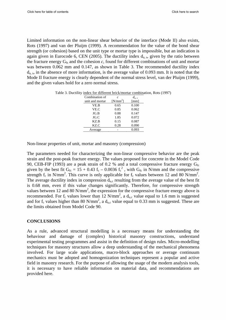
Limited information on the non-linear shear behavior of the interface (Mode II) also exists, Rots (1997) and van der Pluijm (1999). A recommendation for the value of the bond shear strength (or cohesion) based on the unit type or mortar type is impossible, but an indication is again given in Eurocode 6, CEN (2005). The ductility index du, s, given by the ratio between the fracture energy Gfs and the cohesion c, found for different combinations of unit and mortar was between 0.062 mm and 0.147, as shown in Table 3. The recommended ductility index du, s, in the absence of more information, is the average value of 0.093 mm. It is noted that the Mode II fracture energy is clearly dependent of the normal stress level, van der Pluijm (1999), and the given values hold for a zero normal stress.
Table 3. Ductility index for different brick/mortar combination, Rots (1997) Combination of unit and mortar
c [N/mm2]
du, s [mm]
VE.B 0.65 0.100 VE.C 0.85 0.062 JG.B 0.88 0.147 JG.C 1.85 0.072 KZ.B 0.15 0.087 KZ.C 0.28 0.090
Average - 0.093
Non-linear properties of unit, mortar and masonry (compression)
The parameters needed for characterizing the non-linear compressive behavior are the peak strain and the post-peak fracture energy. The values proposed for concrete in the Model Code 90, CEB-FIP (1993) are a peak strain of 0.2 % and a total compressive fracture energy Gfc given by the best fit Gfc = 15 + 0.43 fc – 0.0036 fc
2 , with Gfc in N/mm and the compressive strength fc in N/mm2. This curve is only applicable for fc values between 12 and 80 N/mm2. The average ductility index in compression du,c resulting from the average value of the best fit is 0.68 mm, even if this value changes significantly. Therefore, for compressive strength values between 12 and 80 N/mm2, the expression for the compressive fracture energy above is recommended. For fc values lower than 12 N/mm2, a du,c value equal to 1.6 mm is suggested and for fc values higher than 80 N/mm2, a du,c value equal to 0.33 mm is suggested. These are the limits obtained from Model Code 90.
CONCLUSIONS
As a rule, advanced structural modelling is a necessary means for understanding the behaviour and damage of (complex) historical masonry constructions, understand experimental testing programmes and assist in the definition of design rules. Micro-modelling techniques for masonry structures allow a deep understanding of the mechanical phenomena involved. For large scale applications, macro-block approaches or average continuum mechanics must be adopted and homogenization techniques represent a popular and active field in masonry research. For the purpose of allowing the usage of the modern analysis tools, it is necessary to have reliable information on material data, and recommendations are provided here.
Click here to searchClick here for table of contents
REFERENCES
Azevedo, J., Sincraian, G., Lemos, J.V., “Seismic behavior of blocky masonry structures”, Earthquake Spectra, 16(2), 2000, pp 337-365. Berto, L., Saetta, A., Scotta, R., Vitaliani, R., “Orthotropic damage model for masonry structures”, International Journal for Numerical Methods in Engineering, 55(2), 2002, pp. 127-157. Calderini, C., Lagomarsino, S., A micromechanical inelastic model for historical masonry. Journal of Earthquake Engineering, 10(4), 2006, pp. 453-479. CEB-FIP, Model Code 90, Thomas Telford Ltd., 1993. CEN, EN 1999-1: Eurocode 6 - Design of masonry structures - Part 1-1: General rules for reinforced and unreinforced masonry structures, European Committee for Standardization, 2005. Chong, V.L., Southcombe, C., May, I.M., “The behaviour of laterally loaded masonry panels with openings”, 3th Int. Masonry Conf. Proc. Brit. Mas. Soc., 1994, pp. 178-182. Dhanasekar, M., Page, A.W., Kleeman, P.W., “The failure of brick masonry under biaxial stresses”, Proceedings from the Institution of Civil Engineers - Part 2, 79, 1985, pp. 295-313. Gambarotta, L., Lagomarsino, S., “Damage models for the seismic response of brick masonry shear walls. Part II: The continuum model and its applications.” Earthquake Engineering & Structural Dynamics, 26(4), 1997, pp. 441-462. Ganz, H.R., Thürlimann, B., Tests on masonry walls under normal and shear loading (in German), Report No. 7502-4, Institute of Structural Engineering, ETH Zurich, 1984. Livesley, R.K., “Limit analysis of structures formed from rigid blocks”, International Journal for Numerical Methods in Engineering, 12, 1978, pp 1853-1871. Lopez, J., Oller, S., Oñate, E., Lubliner, J., A homogeneous constitutive model for masonry. International Journal for Numerical Methods in Engineering, 46, 1999, pp. 1651-1671. Lourenço P.B., Computational strategies for masonry structures, PhD Thesis, Delft University of Technology, 1996. Available from www.civil.uminho.pt/masonry. Lourenço, P.B., “Experimental and numerical issues in the modelling of the mechanical behaviour of masonry”, Structural analysis of historical constructions II, 1998, pp. 57-91. Lourenço, P.B., “Anisotropic softening model for masonry plates and shells”, Journal of Structural Engineering, ASCE 126(9), 2000, pp. 1008-1016. Lourenço, P.B., Ramos, L.F., “Characterization of the cyclic behavior of dry masonry joints”, Journal of Structural Engineering, ASCE, 130(5), 2004, pp. 779-786.
Click here to searchClick here for table of contents
Lourenço, P.B., Pina-Henriques, J.L., Masonry micro-modelling: a continuum approach in compression, Computers & Structures, 84(29-30), 2006, pp. 1977-1989. Lourenço, P.B., Rots, J.G., “Multisurface interface model for the analysis of masonry structures”, Journal of Engineering Mechanics, ASCE, 123(7), 1997, pp 660-668. Lourenço, P.B., Rots J.G., Blaauwendraad J., “Continuum model for masonry: Parameter estimation and validation”, Journal of Structural Engineering, 124(6), 1998, pp 642-652. Lourenço, P.B., Rots, J.G., van der Pluijm, R., “Understanding the tensile behaviour of masonry parallel to the bed joints: a numerical approach”, Masonry International, 12(3), 1999, pp. 96-103. Lourenço, P.B., Barros, J.O., Oliveira, J.T., “Shear testing of stack bonded masonry”, Construction and Building Materials, 18, 2004, pp.125-132. Lourenço, P.B., Almeida, J.C., Barros, J.A., “Experimental investigation of bricks under uniaxial tensile testing”, Masonry International, 18(1), 2005, pp.11-20. Magenes, G., “Masonry building design in seismic areas: Recent experiences and prospects from a European standpoint”, First European Conference on Earthquake Engineering and Seismology, 2006, keynote 9. Available from http://www.ecees.org. Maier, G., Papa, E., Nappi, A., “On damage and failure of unit masonry”, Experimental and numerical methods in earthquake engineering, 1991, pp. 223-245. Massart, T.J., Peerlings, R.H.J., Geers, M.G.D., “Mesoscopic modeling of failure and damage-induced anisotropy in brick masonry”, European Journal of Mechanics A/Solids, 23, 2004, p. 719-735. Milani, G., Lourenço, P.B., Tralli, A., “Homogenised limit analysis of masonry walls. Part I: Failure surfaces”, Computers & Structures, 84(3-4), 2006a, pp. 166-180. Milani, G., Lourenço, P.B., Tralli, A., “Homogenised limit analysis of masonry walls. Part II: Structural applications, Computers & Structures, 84(3-4), 2006b, pp. 181-195. Milani, G., Lourenço, P.B., Tralli, A., “A homogenization approach for the limit analysis of out-of-plane loaded masonry walls”, Journal of Structural Engineering, ASCE, 2006c, pp. 1650-1663. Oliveira, D.V., Lourenço, P.B., “Implementation and validation of a constitutive model for the cyclic behavior of interface elements”, Computers & Structures, 82 (17-19), 2004, pp 1451-1461. Orduña, A., Lourenço, P.B., “Three-dimensional limit analysis of rigid blocks assemblages. Part II: Load-path following solution procedure and validation”, International Journal of Solids and Structures, 42(18-19), 2005, pp. 5161-5180. Page, A.W., “Finite element model for masonry”, Journal of the Structural Division, ASCE, 104(8), 1978, pp 1267-1285.
Click here to searchClick here for table of contents
Page, A.W., “The biaxial compressive strength of brick masonry”, Proceedings from the Institution of Civil Engineers - Part 2, 71, 1981, pp. 893-906. Page, A.W., “The strength of brick masonry under biaxial compression-tension”, International Journal of Masonry Construction 3(1), 1983, p. 26-31. Pande, G.N., Liang, J.X., Middleton, J., “Equivalent elastic moduli for unit masonry”, Computers and Geotechnics, 8, 1989, pp. 243-265. Pietruszczak, S., Niu, X., “A mathematical description of macroscopic behaviour of brick masonry”, International Journal of Solids and Structures, 29(5), 1992, pp. 531-546. Podestà, S., “A damage model for the analysis of the seismic response of monumental buildings”, Journal of Earthquake Engineering, 9(3), 2005, pp. 419-444. Rots J.G., “Numerical simulation of cracking in structural masonry”, Heron, 36(2), 1991, pp. 49-63. Rots, J.G. (Editor), Structural masonry: An experimental/numerical basis for practical design rules, Balkema, 1997. Sutcliffe D.J., Yu H.S., Page A.W., “Lower bound limit analysis of unreinforced masonry shear walls”, Computers & Structures, 79, 2001, pp. 1295-1312. van der Pluijm, R., Out of plane bending of masonry: Behaviour and strength, Ph.D. Dissertation. Eindhoven University of Technology, 1999. Vasconcelos, G., Lourenço, P.B., Alves C.A.S., Pamplona, J., “Experimental characterization of the tensile behaviour of granites”, International Journal of Rock Mechanics and Mining Sciences, 2007, in press. Zucchini, A., Lourenço, P.B. “A micro-mechanical model for the homogenization of masonry”, International Journal of Solids and Structures, 39, 2002, pp. 3233-3255. Zucchini A, Lourenço P.B., “A coupled homogenisation-damage model for masonry cracking”, Computer & Structures, 82, 2004, pp. 917-929. Zucchini A, Lourenço P.B., “Mechanics of masonry in compression: Results from a homogenisation approach”, Computer & Structures, 85(3-4), 2007, pp. 193-204.
Click here to searchClick here for table of contents