stratix ii performance and logic efficiency analysis - …€¦ · · 2018-04-14stratix ii...
TRANSCRIPT
White Paper
Stratix II Performance and Logic Efficiency Analysis
September 2006, ver. 2.0 1
WP-STXIIPLE-2.0
Introduction
Pursuing higher performance and density of FPGA devices by migrating to a smaller-geometry silicon process presents challenges with power consumption issues. The power consumption of a device based on the 90-nm process rises considerably along with the increase in performance and density. To obtain the desired performance and density without the power consumption penalty requires an improvement to the logic structure in the FPGAs.
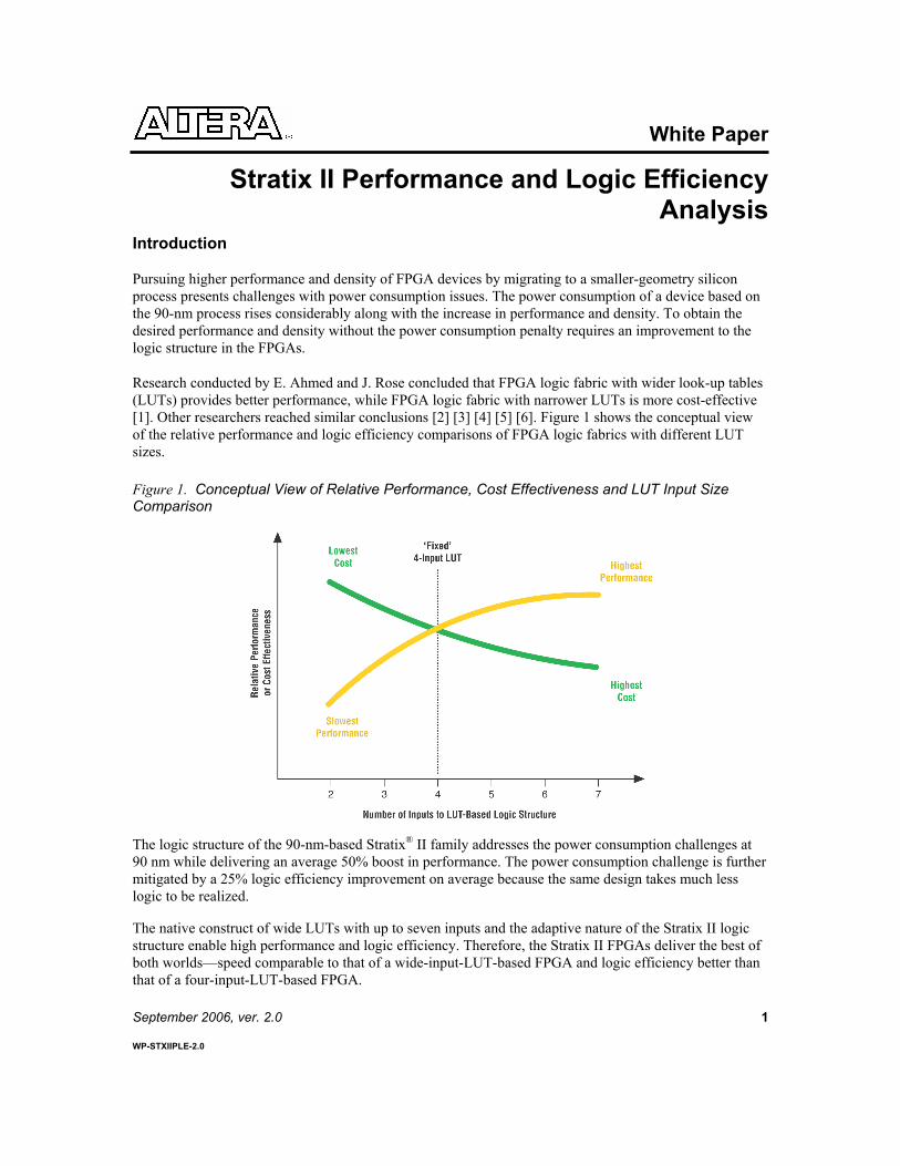
Research conducted by E. Ahmed and J. Rose concluded that FPGA logic fabric with wider look-up tables (LUTs) provides better performance, while FPGA logic fabric with narrower LUTs is more cost-effective [1]. Other researchers reached similar conclusions [2] [3] [4] [5] [6]. Figure 1 shows the conceptual view of the relative performance and logic efficiency comparisons of FPGA logic fabrics with different LUT sizes.
Figure 1. Conceptual View of Relative Performance, Cost Effectiveness and LUT Input Size Comparison
The logic structure of the 90-nm-based Stratix® II family addresses the power consumption challenges at 90 nm while delivering an average 50% boost in performance. The power consumption challenge is further mitigated by a 25% logic efficiency improvement on average because the same design takes much less logic to be realized.
The native construct of wide LUTs with up to seven inputs and the adaptive nature of the Stratix II logic structure enable high performance and logic efficiency. Therefore, the Stratix II FPGAs deliver the best of both worlds—speed comparable to that of a wide-input-LUT-based FPGA and logic efficiency better than that of a four-input-LUT-based FPGA.

Stratix II Performance and Logic Efficiency Analysis Altera Corporation
2
This paper shows the performance and logic efficiency advantages of the new and innovative Stratix II logic structure through extensive empirical benchmark data and detailed analysis. Empirical benchmark data is presented first, followed by an introduction to the Stratix II logic structure. Detailed performance and logic-efficiency analysis is then provided.
Benchmark Setup & Data
The benchmark comparison uses 80 real customer designs. The comparison of the performance and logic utilization for each design is based on data reported by the Quartus® II software after place-and-route for Stratix and Stratix II families. Table 1 shows the software tool used in the benchmark.
Table 1. Benchmark Software Setup
FPGA Family Synthesis Tool Place-and-Route Tool Stratix II Quartus Integrated Synthesis Quartus II version 4.0 pre-release build Stratix Quartus Integrated Synthesis Quartus II version 4.0 pre-release build
Stratix II Logic Resource Representation in the Quartus II Software
The basic building block of logic in the Stratix II devices is an adaptive logic module (ALM). Each ALM contains a variety of LUT-based resources, two full adders, carry-chain segments, two flipflops, and many additional logic enhancements that can be adaptively divided into two adaptive LUTs (ALUTs). Figure 2 shows the relationship of the ALM and ALUTs.
Figure 2. ALM & ALUT’s Relationship
Refer to the Appendix for more information on Stratix II logic utilization reporting in the Quartus II software.
Altera Corporation Stratix II Performance and Logic Efficiency Analysis
3
Benchmark Data
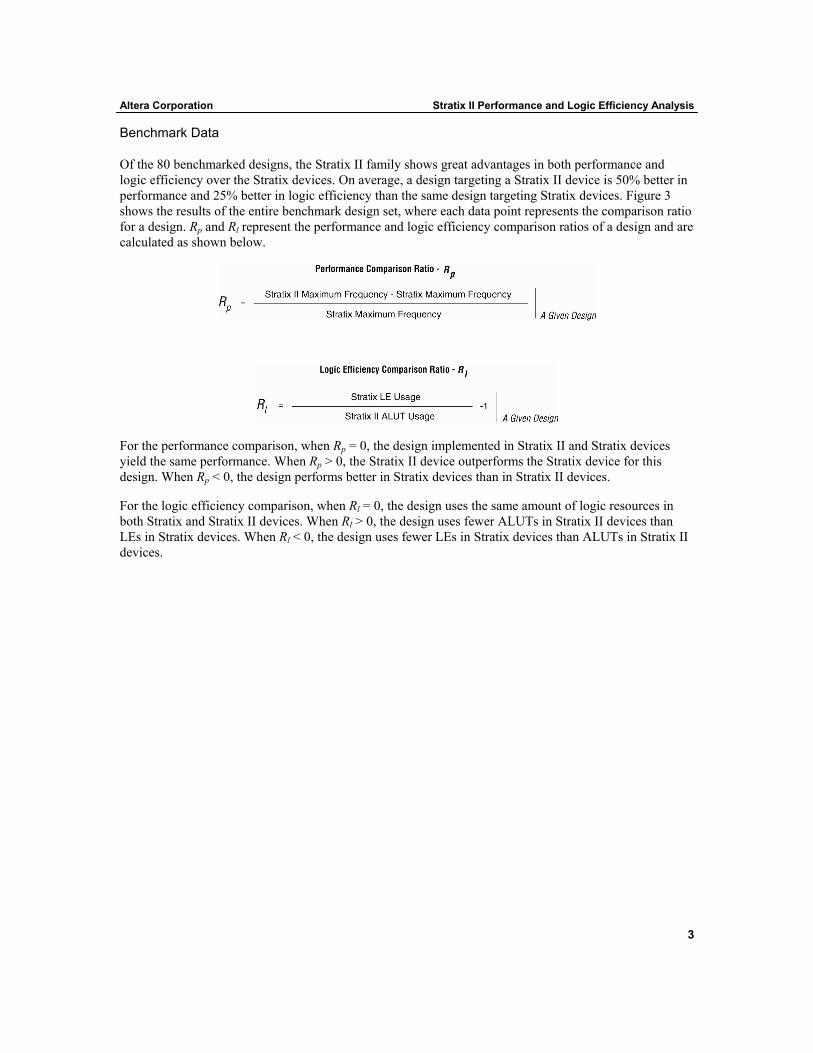
Of the 80 benchmarked designs, the Stratix II family shows great advantages in both performance and logic efficiency over the Stratix devices. On average, a design targeting a Stratix II device is 50% better in performance and 25% better in logic efficiency than the same design targeting Stratix devices. Figure 3 shows the results of the entire benchmark design set, where each data point represents the comparison ratio for a design. Rp and Rl represent the performance and logic efficiency comparison ratios of a design and are calculated as shown below.
For the performance comparison, when Rp = 0, the design implemented in Stratix II and Stratix devices yield the same performance. When Rp > 0, the Stratix II device outperforms the Stratix device for this design. When Rp < 0, the design performs better in Stratix devices than in Stratix II devices.
For the logic efficiency comparison, when Rl = 0, the design uses the same amount of logic resources in both Stratix and Stratix II devices. When Rl > 0, the design uses fewer ALUTs in Stratix II devices than LEs in Stratix devices. When Rl < 0, the design uses fewer LEs in Stratix devices than ALUTs in Stratix II devices.

Stratix II Performance and Logic Efficiency Analysis Altera Corporation
4
Figure 3. Customer Design Benchmark Relative Performance & Logic Efficiency Comparison
Note: (1) The performance and logic utilization of a design depends on the design details, optimization techniques, CAD software
algorithms, and device capabilities. The benchmark data shows typical results. Individual results may vary with designs.
The benchmarked designs targeting the Stratix II family show better performance and use less logic resources compared to the same design implemented in a Stratix device. The new and innovative logic structure of the Stratix II device contributed greatly in boosting the performance and reducing the logic resources needed for a given design. The Quartus II software automatically takes full advantage of the Stratix II logic structure innovation. On average, the Stratix II family offers a 50% performance advantage and 25% better logic efficiency when compared to the Stratix family.
Stratix II Adaptive Logic Module
The logic structure of a Stratix II device is based on a matrix of logic array blocks (LABs) for implementing custom logic functions. Each LAB contains eight adaptive logic modules (ALMs) that

Altera Corporation Stratix II Performance and Logic Efficiency Analysis
5
represent the Stratix II family’s basic building blocks of logic, providing efficient implementation of user logic functions. Each ALM can be configured to perform combinational logic functions or logic-and-arithmetic operations.
ALM Adaptive Combinational Logic Support
Each ALM contains a variety of look-up table (LUT)-based resources that can be adaptively divided between two ALUTs. With up to eight inputs to the combinational logic block, one ALM can implement various combinations of two functions. Table 2 shows a summary of various supported combinational logic configurations in an ALM. Refer to the Stratix II Device Handbook for detailed architecture descriptions.
Table 2. ALM Adaptive Combinational Logic Configurations
Configuration Description
One Stratix II ALM can be configured to implement two independent four-input (or smaller) LUTs. This configuration can be viewed as the “backward-compatibility” mode. Designs that are optimized for the traditional four-input LUT (4-LUT) FPGAs can easily be migrated to the Stratix II family.
One Stratix II ALM can be configured to implement a five-input LUT (5-LUT) and a three-input LUT (3-LUT). The inputs to the two LUTs are independent of each other. The 3-LUT can be used to implement any logic function that has three or fewer inputs. Therefore, 5-LUT-2-LUT is also allowed.
One Stratix II ALM can be configured to implement a five-input LUT and a four-input LUT. One of the inputs is shared between the two LUTs. The 5-LUT has up to four independent inputs. The 4-LUT has up to three independent inputs. The sharing of inputs between LUTs is very common in FPGA designs, and the Quartus II software automatically seeks logic functions that are structured in this manner.
One Stratix II ALM can be configured to implement two five-input LUTs (5-LUTs). Two of the inputs between the LUTs are common, and up to three independent inputs are allowed for each 5-LUT.
6-LUT
A Stratix II ALM can implement any six-input function (6-LUT). If there are two six-input functions that have the same logic operation and four shared inputs, then the two six-input functions can be implemented in one Stratix II ALM For example, a 4x2 crossbar switch that has four data input lines and two sets of unique select signals requires four LEs in the Stratix family. In the Stratix II family, this function only requires one ALM. Another example is a six-input AND gate. An ALM can implement two six-input AND gates that have four common inputs. The same function would require three LEs if implemented in a Stratix device.
One Stratix II ALM in the extended mode can implement a subset of a seven-variable function. The Quartus II software automatically recognizes the applicable seven-input function and fits it into an ALM. Refer to the Stratix II Device Handbook for detailed information about the types of seven-input functions that can be implemented in an ALM.

Stratix II Performance and Logic Efficiency Analysis Altera Corporation
6
ALM Arithmetic Support
In addition to the adaptive combinational logic support, each ALM contains two full adders to perform various arithmetic operations. ALMs support two arithmetic operation modes:
Arithmetic Mode Shared Arithmetic Mode
Table 3 shows a summary of the two arithmetic operation configurations in an ALM. Refer to the Stratix II Device Handbook for detailed architecture descriptions.
Table 3. ALM Arithmetic Operation Configurations
Mode Configuration Description Arithmetic Mode
An ALM can be configured to implement complex logic-arithmetic-combined operations. The arithmetic operation is computed by the two dedicated full adders, leaving the LUTs available to perform pre-adder logic. For example, data selection logic before the summation can be easily combined with the summation operation in the same ALM, which improves the performance and reduces the logic resource usage.
Shared Arithmetic Mode
An ALM can be configured to perform complex arithmetic operations by allowing the sharing of LUT resources between the ALUTs. For example, one ALM can be configured to perform two three-input adders. Allowing the summation of three numbers at once greatly reduces the number of summation stages in an adder tree, thus improving the performance and reducing logic resource usage.
Stratix II Performance & Logic Efficiency Advantages
The Stratix II family delivers an average 50% performance advantage as indicated by the empirical data. The Stratix II family’s new and innovative logic structure goes beyond the simple fixed-size four-input LUT structure and extends its logic capacity to efficiently construct any logical functions with five or six inputs in one entity. Also, a Stratix II ALM can implement many seven-input functions. By supporting logical functions with more than four variables per ALM, the Stratix II logic structure increases the performance of a design by:
Reducing the number of logic levels required for the overall combinational logic Reducing the extra programmable routing needed in the simple fixed-size four-input LUT
implementation Reducing the stress on general routing resources

Altera Corporation Stratix II Performance and Logic Efficiency Analysis
7
Research has shown that wider LUTs provide better performance, while narrower LUTs provide better logic efficiency. Stratix II ALMs offer not only the desired performance, but also adaptively accommodate the logic functions with different numbers of inputs to provide exceptional logic efficiency that is 25% better than prior FPGAs.
An analysis of a customer design suite similar to that benchmarked in Figure 3 shows that the LUTs’ size in a synthesized design is widely spread between LUTs with one input to seven inputs. See Figure 4. An FPGA’s logic structure of fixed-size four-input LUTs is quite wasteful when implementing logic functions that do not have exactly four variables. The adaptive nature of the ALMs can minimize the logic resource inefficiency caused by partially utilized LUTs in a fixed-size LUT FPGA architecture. See Figure 5.
Figure 4. LUT Distribution Analysis
7-Input LUT7%
6-Input LUT12%
5-Input LUT29%
4-Input LUT18%
3-Input LUT16%
2-Input LUT13%
1-Input LUT7%
Figure 5. Five-Variable Function Implementation Comparison Between a Fixed-Size Four-Input LUT FPGA & Stratix II Devices

Stratix II Performance and Logic Efficiency Analysis Altera Corporation
8
The Stratix II ALMs can effectively reduce the logic resource requirements of a design by:
Optimally creating functions with larger input counts and packing them with functions with smaller input counts (for example, a five-input and a three-input function can be placed together in one ALM in Stratix II devices)
Drastically reducing the need for logic duplication by sharing logic resources for different combinational logic with common inputs
Efficiently implementing complex arithmetic functions and combining logic and arithmetic operations such as data selection before summation and subtraction
Efficiently implementing high-input-count arithmetic functions such as an adder tree Allowing register packing using a register chain
The Stratix II family provides an ideal design platform to efficiently implement high-performance systems.
Stratix II ALM Adaptive Logic Configuration Advantages
The key innovation of the flexible ALM lies in the ability of a Stratix II ALM to implement two look-up tables of the same or different number of inputs. By sharing the resources in the ALM in intelligent ways, the Stratix II ALM requires only slightly more layout area than two simple four-input LUTs, yet it is vastly more powerful.
The Quartus II software automatically utilizes the full potential of the Stratix II ALM to fit two LUTs with the same or different sizes in one ALM. For example, when implementing a function of three variables in the traditional four-input LUT structure, the fourth, unused port is wasted. However, for Stratix II devices, this otherwise wasted resource can be reused to form a free five-input LUT in the other half of the ALM. See Figure 6.
Figure 6. Stratix II ALM Logic Efficiency Example

Altera Corporation Stratix II Performance and Logic Efficiency Analysis
9
Stratix II ALM Register Packing Advantages
The efficiency of a design’s logic utilization depends on many different factors—the FPGA architecture, the synthesis tool, the place-and-route tool, and the coding of the design itself. The Stratix II architecture is designed to be highly routable by allowing every ALM in the device to use both its LUT resources and registers for independent functions and still route successfully.
Altera’s Quartus II software is equipped with a powerful feature called register packing to fully leverage this architectural advantage. Register packing aggressively makes an ALM perform “double-duty” by actively taking registers in a design and packing them into unrelated ALMs that only use the LUT resources. This process reduces the size of a design considerably and often fits a design into a smaller device.
Case Study 1: Six-Variable Logic Function
Implementing a six-variable logic function using a four-input-LUT FPGA architecture takes two or more four-input LUTs that are cascaded. However, the Stratix II logic structure supports the native implementation of wide-input LUTs that boosts the performance and reduces the logic resources needed.
Figure 7 shows Stratix and Stratix II device implementations of a six-variable function as described in the equation below. When implementing this six-input function in Stratix devices, LEs are cascaded to form two logic levels. However, the same function fits in a single entity in the Stratix II logic structure, removing both the extra programmable logic routing and a logic level.
EFBCDAFCDEBAEFDCABFDEABCFEDBCADEFCBAEFCDABABCDEFFEDCBAf |||||||),,,,,( =
Figure 7. Stratix Versus Stratix II Complex Six-Input Function Implementation Comparison
Stratix II Performance and Logic Efficiency Analysis Altera Corporation
10
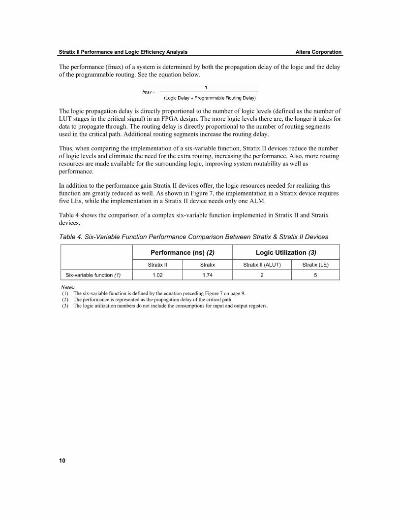
The performance (fmax) of a system is determined by both the propagation delay of the logic and the delay of the programmable routing. See the equation below.
The logic propagation delay is directly proportional to the number of logic levels (defined as the number of LUT stages in the critical signal) in an FPGA design. The more logic levels there are, the longer it takes for data to propagate through. The routing delay is directly proportional to the number of routing segments used in the critical path. Additional routing segments increase the routing delay.
Thus, when comparing the implementation of a six-variable function, Stratix II devices reduce the number of logic levels and eliminate the need for the extra routing, increasing the performance. Also, more routing resources are made available for the surrounding logic, improving system routability as well as performance.
In addition to the performance gain Stratix II devices offer, the logic resources needed for realizing this function are greatly reduced as well. As shown in Figure 7, the implementation in a Stratix device requires five LEs, while the implementation in a Stratix II device needs only one ALM.
Table 4 shows the comparison of a complex six-variable function implemented in Stratix II and Stratix devices.
Table 4. Six-Variable Function Performance Comparison Between Stratix & Stratix II Devices
Performance (ns) (2) Logic Utilization (3) Stratix II Stratix Stratix II (ALUT) Stratix (LE)
Six-variable function (1) 1.02 1.74 2 5
Notes: (1) The six-variable function is defined by the equation preceding Figure 7 on page 9. (2) The performance is represented as the propagation delay of the critical path. (3) The logic utilization numbers do not include the consumptions for input and output registers.

Altera Corporation Stratix II Performance and Logic Efficiency Analysis
11
Case Study 2: Crossbar Switch
Crossbar switches are commonly found in telecommunication designs to switch data from one port to another. As the amount of data continues to rapidly increase, the performance of the crossbar switches is critical in meeting the data throughput requirement in a system.
The example analyzed here is a crossbar switch that has four data input ports (A-D), two sets of select input ports (selectA and selectB), and two data output ports. The two sets of select signals (two bits per set) are used to switch the data from input ports to output ports. Figure 8 compares the implementation of a 4x2 crossbar switch in Stratix and Stratix II devices.
Figure 8. Stratix Versus Stratix II 4x2 Crossbar Switch Implementation Comparison
Because the LUT size in Stratix devices is limited to four inputs, the switching operation must be implemented in two sets of two cascading LUTs in order to accommodate all eight inputs to each bit of a 4x2 crossbar switch. The speed of the system is limited by the two logic levels and the programmable routing delay of the data path.
View each one-bit 4x2 crossbar switch as two six-variable logic functions, and each function propagates one of the four data inputs to the output based on the two unique select signals. Each Stratix II ALM can implement two six-variable functions that perform the same logic operation with four shared variables. Thus, each bit of the 4x2 crossbar switch can be absorbed into just one ALM, improving the performance by eliminating one logic level and the programmable routing. Also, the logic resource utilization in Stratix II devices is reduced by half. Table 5 shows the eight-bit 4x2 crossbar switch benchmark results.

Stratix II Performance and Logic Efficiency Analysis Altera Corporation
12
Table 5. Eight-Bit 4x2 Crossbar Switch Benchmark Comparison Between Stratix & Stratix II Devices
Performance (ns) Logic Utilization (1) Stratix II Stratix Stratix II (ALUT) Stratix (LE)
8-bit 4x2 crossbar switch 1.44 2.12 (1) 16 32
Note: (1) The logic utilization numbers do not include the consumptions for input and output registers.
Case Study 3: Adder Tree
Adder trees are often found in DSP applications, for example, the correlators in the 3G wireless basestation channel cards or the partial-product summation in the logic-based multipliers. The Stratix II ALM offers a great performance advantage in adder tree implementation by supporting the summation of three numbers in one step. Figure 9 shows the implementation of a simple three-input adder in Stratix and Stratix II devices.
Figure 9. Stratix Versus Stratix II Three-Input Adder Implementation
It is clear that when a three-input add operation is implemented in Stratix devices or any FPGA family that only supports two-input add operations in its logic structure the sum is generated by repeatedly adding two numbers each time. The performance of this binary-tree style summation is limited by the delay of each add stage as well as the delay of the programmable routing between each add stage.
The ternary adder support (in shared arithmetic mode) in Stratix II ALMs simply collapses the two add stages into one and improves the performance by eliminating one add stage and the extra programmable routing. The number of add stage reductions can be estimated through the equation below.
Add Stage Reduction = ceiling(log2 (n)) – ceiling(log3 (n)) where n is the count of input numbers
Altera Corporation Stratix II Performance and Logic Efficiency Analysis
13
As the number of inputs to the adder tree increases, the number of summation stages increases. Thus, by allowing the addition of three numbers at once in Stratix II ALMs, the performance gain offered by Stratix II devices becomes significant. For fully pipelined implementation of an adder tree, Stratix II devices reduce the latency by reducing the add stages.
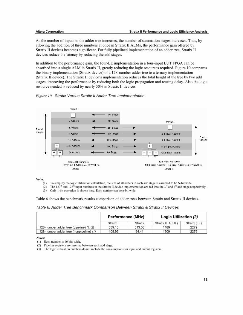
In addition to the performance gain, the four-LE implementation in a four-input LUT FPGA can be absorbed into a single ALM in Stratix II, greatly reducing the logic resources required. Figure 10 compares the binary implementation (Stratix device) of a 128-number adder tree to a ternary implementation (Stratix II device). The Stratix II device’s implementation reduces the total height of the tree by two add stages, improving the performance by reducing both the logic propagation and routing delay. Also the logic resource needed is reduced by nearly 50% in Stratix II devices.
Figure 10. Stratix Versus Stratix II Adder Tree Implementation
Notes: (1) To simplify the logic utilization calculation, the size of all adders in each add stage is assumed to be N-bit wide. (2) The 127th and 128th input numbers in the Stratix II device implementation are fed into the 3rd and 4th add stage respectively. (3) Only 1-bit operation is shown here. Each number can be n-bit wide.
Table 6 shows the benchmark results comparison of adder trees between Stratix and Stratix II devices.
Table 6. Adder Tree Benchmark Comparison Between Stratix & Stratix II Devices
Performance (MHz) Logic Utilization (3) Stratix II Stratix Stratix II (ALUT) Stratix (LE)
128-number adder tree (pipeline) (1, 2) 339.10 313.58 1489 2279 128-number adder tree (nonpipeline) (1) 108.92 64.41 1209 2279
Notes: (1) Each number is 16 bits wide. (2) Pipeline registers are inserted between each add stage. (3) The logic utilization numbers do not include the consumptions for input and output registers.

Stratix II Performance and Logic Efficiency Analysis Altera Corporation
14
Case Study 4: Data Select Before Addition and Subtraction
Simple arithmetic operations such as additions and subtractions are very common in designs. These operations very often have associated logic functions in front of them. For example, take the following function:
If select=0, then A op B, else A op C. where A, B, and C are all n-bit numbers.
op can be either addition or subtraction controlled by AddSub signal
In the Stratix architecture, for each bit of data, an LE is needed for multiplexing B and C inputs based on select. Then, another LE is needed for A to be added to the chosen input. However, in the Stratix II architecture, one ALM can perform both the B and C multiplexing and adding/subtracting for 2 bits. Therefore, the Stratix II architecture achieves a reduction in logic levels compared to Stratix devices. See Figure 11.
When it is implemented in a generic four-input LUT architecture, this function takes two logic levels and six LEs. Stratix devices reduce the logic usage by 33% through the use of the dedicated add/sub control signal in the logic array block (LAB). A Stratix II device can fit the entire design into one logic level in one ALM and offers a 50% and 66% savings in logic resource usage compared to a Stratix or generic four-input LUT architecture respectively.
Figure 11. Data Select Before AddSub Function Implementation Comparison
Table 7 shows the benchmark results comparison of an 8-bit data-select-before-addition/subtraction between Stratix and Stratix II devices.
Table 7. Eight-Bit Data Select Before Add/Sub Comparison Between Stratix and Stratix II Devices
Performance (MHz) Logic Utilization (2) Stratix II Stratix Stratix II (ALUT) Stratix (LE)
8-bit data select before add/sub 668.9 (1) 388.5 9 16
Notes: (1) The performance in MHz is derived based on the total propagation delay of the critical path. (2) The logic utilization numbers do not include the consumptions for input and output registers.

Altera Corporation Stratix II Performance and Logic Efficiency Analysis
15
Performance and Logic Efficiency Benchmark Data
In addition to the case studies discussed earlier, Table 8 provides additional benchmark data comparing Stratix and Stratix II device implementations of simple circuits that are the building blocks of a system. Stratix II devices clearly show great performance and logic efficiency advantage over Stratix devices.
Table 8. Design Building Block Performance & Logic Efficiency Comparison Between Stratix & Stratix II Devices
Performance (MHz) Logic Utilization Design Category Design Description
Stratix II Stratix Stratix II (ALUT) Stratix (LE)
128 number, 16-bits per number adder tree (non-pipelined). 108.92 64.41 1209 2279
Adder tree
128 number, 16-bits per number adder tree (pipelined). 339.31 (4) 313.58 1489 2279
Barrel shifter 32-bit barrel shifter with rotate direction (up/down) control. 318.17 186.99 413 627
Complex arithmetic
A or B (selected by Select signal) is added to or subtracted by C (8-bits per number). 668.9 (3) 388.5 9 16
Crossbar switch 8-bit 4x2 crossbar switch 696.86 (3) 472.81 (3) 16 32 DES (2) Data encryption standard 273.07 190.44 2659 4440 DIP-four-parity checker Diagonal interleaved parity CRC checking 231.54 181.95 180 238 Multiplexer 32-bus-to-1, 16-bits per bus multiplexer 324.99 230.84 280 336 Dedicated multiplier
36-bit x 36-bit signed multiplication using dedicated multiplier. One pipeline stage. 363.24 278.78 0 (5) 0 (5)
Logic-based multiplier
18-bit x 18-bit signed logic-based multiplier. No pipelining. 158.73 81.71 312 409
Multiplier - accumulator (MAC)
18-bit signed multiply and accumulate with a pipeline stage between the multiplier output and accumulator. 363.24 278.78 0 (5) 0 (5)
Generic six-input function
A generic six-input function with eight product terms, and each product term is a function of all six inputs. 985.22 (3) 573.39 (3) 2 5
Finite state machine (FSM)
20-input, 20-output generic finite state machine 516.26 (3) 436.68 (3) 53 58
Notes: (1) The logic utilization numbers do not include the consumptions for input and output registers. (2) The DES design benchmark is based on the source written by Rudolf Usselmann. (3) The performance in MHz is derived based on the total propagation delay of the critical path. (4) Latency is reduced by two. (5) The circuit is implemented in a DSP block.

Stratix II Performance and Logic Efficiency Analysis Altera Corporation
16
Conclusion
The new and innovative Stratix II logic structure contributes significantly in providing the unprecedented performance that is on average, 50% better than prior FPGA families. Also, the flexible ALMs effectively reduce the logic resources requirement by adaptively matching the need of a design. Our benchmark data shows that, on average, Stratix II FPGAs are 25% better in logic efficiency over Stratix devices. The empirical benchmark data and architecture analysis demonstrates that the 90-nm-based Stratix II FPGA family provides a cost effective and superior design platform for high-performance systems.
Altera Corporation Stratix II Performance and Logic Efficiency Analysis
17
Appendix – Stratix II Logic Utilization Reporting in the Quartus II Software
For Stratix II devices, the Quartus II software reports the total number of adaptive look-up tables (ALUTs) used to hold combinational logic functions and registers in the current design. If either the register or the combinational logic in an ALUT is used, the ALUT is counted as used. The Quartus II software also reports the number of unused ALUTs that have been blocked due to the routing needed by the other ALUTs in the ALM.
For example, if an ALM contains an ALUT that implements a seven-input combinational function and an unrelated register, then there are no more connections available to feed either the register or the combinational logic of the other ALUT in the ALM, so that ALUT is unusable. If an ALM contains an ALUT that implements a six-input function, then there are two available connections that can be used to feed a register in the other ALUT, or one of the six inputs to the first ALUT might also feed the second register directly.
The Quartus II fitter reports the total number of ALUTs used, taking into account both ALUTs that are using either their combinational logic or register, and those that are partially or totally blocked by another ALUT in the same ALM. This is shown in the Fitter Summary and the Fitter Resource Usage Summary sections as Total ALUTs. This number should be used to determine how full the device is with the current design. Figure 12 shows an example of the Quartus II Fitter Resource Usage Summary.

Stratix II Performance and Logic Efficiency Analysis Altera Corporation
18
Figure 12. Quartus II Fitter Resource Usage Summary Example

Altera Corporation Stratix II Performance and Logic Efficiency Analysis
19
Total ALUTs is broken down in the Fitter Resource Usage Summary by whether a cell is counted because it actually contains logic or because it is blocked by its neighbor. Table 9 describes the Fitter Resource Usage Summary.
Table 9. Fitter Resource Usage Summary Description
Category Description Total ALUTs ALUTs Used shows the total number of ALUTs that contain combinational
logic functions and registers. This total is further divided by what occupies the logic cell. A high number of “register only” and “combinational only” logic cells could mean that more free space could be recovered by more aggressive register packing.
ALUTs Unavailable shows the total number of ALUTs that have been blocked by their neighbor. An ALUT is only reported here if there is no combinational function or register in this location and the other ALUT in the ALM has been used by a six- or seven-input combinational function. The summary also shows the number of six- and seven-input functions causing blockage.
ALUT Usage by Number of Inputs
Shows the distribution of combinational functions in the design, the number of combinational cells that exist just to route data to a register, and the number of ALUTs that contain just a register. The total of 7, 6, 5, 4, and <=3 input functions will equal the sum of combinational cells reported in ALUTs Used.
ALUTs Without a Partner Shows how many ALUTs occupy an ALM where the other ALUT in the ALM is empty. This is also broken down by the number of inputs to the combinational function and can indicate how much logic is still left to be packed together.
ALUTs by Mode Shows many ALUTs are in each of the four modes shown in the data sheet.
The rest of the logic section, Total Registers, Total ALMs, and Total LABs, is self explanatory. Compare ALUTs without a partner to Total ALMs to judge the percentage of ALMs that have space available.
Throughout this white paper, the ALUT count reported by the Quartus II software for a design implemented in a Stratix II device is used to directly compare to the Stratix LE count of the same design.
Synthesis Tools Resource Utilization Reporting
When a design is successfully synthesized, synthesis tools often report the estimation for the logic and resources used by the design. The logic utilization reported by the synthesis tool should only be treated as a rough estimate because of advanced fitting algorithms, such as register packing, and other factors such as black-boxing, megafunctions, and Quartus II netlist optimization techniques. True logic utilization should be obtained from the place-and-route tool’s compilation reports. [Refer to Altera® Tech Brief, TB 84: “Differences in Logic Utilization between Quartus II & Synplify Report Files”]

Stratix II Performance and Logic Efficiency Analysis Altera Corporation
20
References
[1] E. Ahmed and J. Rose, "The Effect of LUT and Cluster Size on Deep-Submicron FPGA Performance and Density," in FPGA 2000, ACM Symp. FPGAs, February 2000, pp. 3-12
[2] J. Kouloheris and A.El Gamal, “FPGA Performance vs. Cell Granularity”, Proc. of Custom Integrated Circuits Conference, May 1991, pp. 6.2.1 - 6.2.4.
[3] J. Kouloheris and A.El Gamal, “FPGA Area vs. Cell Granularity - PLA Cells”, Proc. of Custom Integrated Circuits Conference, May 1992.
[4] J. Rose, R.J. Francis, D. Lewis and P. Chow, “Architecture of Field-Programmable Gate Arrays: The Effect of Logic Functionality on Area Efficiency”, IEEE Journal of Solid-State Circuits, 1990.
[5] S. Singh, “The Effect of Logic Block Architecture on FPGA Performance”, M.A.Sc. Thesis, University of Toronto, 1991.
[6] S. Singh, J. Rose, P. Chow and D. Lewis, “The Effect of Logic Block Architecture on FPGA Performance”, IEEE Journal of Solid-State Circuits, 1992.
101 Innovation Drive San Jose, CA 95134 (408) 544-7000 www.altera.com
Copyright © 2006 Altera Corporation. All rights reserved. Altera, The Programmable Solutions Company, the stylized Altera logo, specific device designations, and all other words and logos that are identified as trademarks and/or service marks are, unless noted otherwise, the trademarks and service marks of Altera Corporation in the U.S. and other countries.* All other product or service names are the property of their respective holders. Altera products are protected under numerous U.S. and foreign patents and pending applications, maskwork rights, and copyrights. Altera warrants performance of its semiconductor products to current specifications in accordance with Altera’s standard warranty, but reserves the right to make changes to any products and services at any time without notice. Altera assumes no responsibility or liability arising out of the application or use of any information, product, or service described herein except as expressly agreed to in writing by Altera Corporation. Altera customers are advised to obtain the latest version of device specifications before relying on any published information and before placing orders for products or services.