stoneridge electronics ltd - typepadstoneridgeworkshopsupport.typepad.com/training/dd55381... ·...
TRANSCRIPT

DD55381 Rev 031
Stoneridge Electronics Ltd
Electronic Road Speed LimiterTraining Course
DD55381 Rev 032
Stoneridge Electronics LtdCOPYRIGHT
This training course and all material used and issued throughout this course is the sole Copyright of Stoneridge Electronics Ltd.
The information contained in this document is the Property of Stoneridge Electronics Ltd. and should not be disclosed, reproduced in whole or in part, or used under any condition by anyone without the written authority of Stoneridge Electronics Ltd.
DD55381 Rev 033
Course Plan
Health & Safety Brief
Introduction to Stoneridge Electronics
Road Speed Limiter Legislation & Vehicle Requirements
The Stoneridge Electronics 9700 Electronic Road Speed Limiter
Lunch
Fitting the 9700 Electronic Road Speed Limiter
Calibrating and Programming the 9700 Electronic Road Speed Limiter
Using a MKII Tachograph Programmer as a Speed Simulator
Testing a Programmed 9700 Electronic Road Speed Limiter
Practical Exercise Using a 9700 Electronic Road Speed Limiter
Exam
Issue of Certificates and Calibration Packs
DD55381 Rev 034
Statement
This course has been written in conjunction with VOSA published Road Speed Limiter documents
This is a VOSA approved training course
DD55381 Rev 035
Section 1
Health & Safety
DD55381 Rev 036
Health & Safety
In the event of the fire alarm sounding, personnel should leave the building by the nearest practical exit, keeping traffic routes clear for emergency services, and gather at assembly point 6 at the front of the building
DO NOT STOP TO TAKE POSSESSIONS WITH YOU OR GO BACK FOR THEM
DO NOT RE-ENTER THE BUILDING UNTIL INSTRUCTED BY THE EVACUATION COORDINATOR OR HIS DEPUTY
DD55381 Rev 037
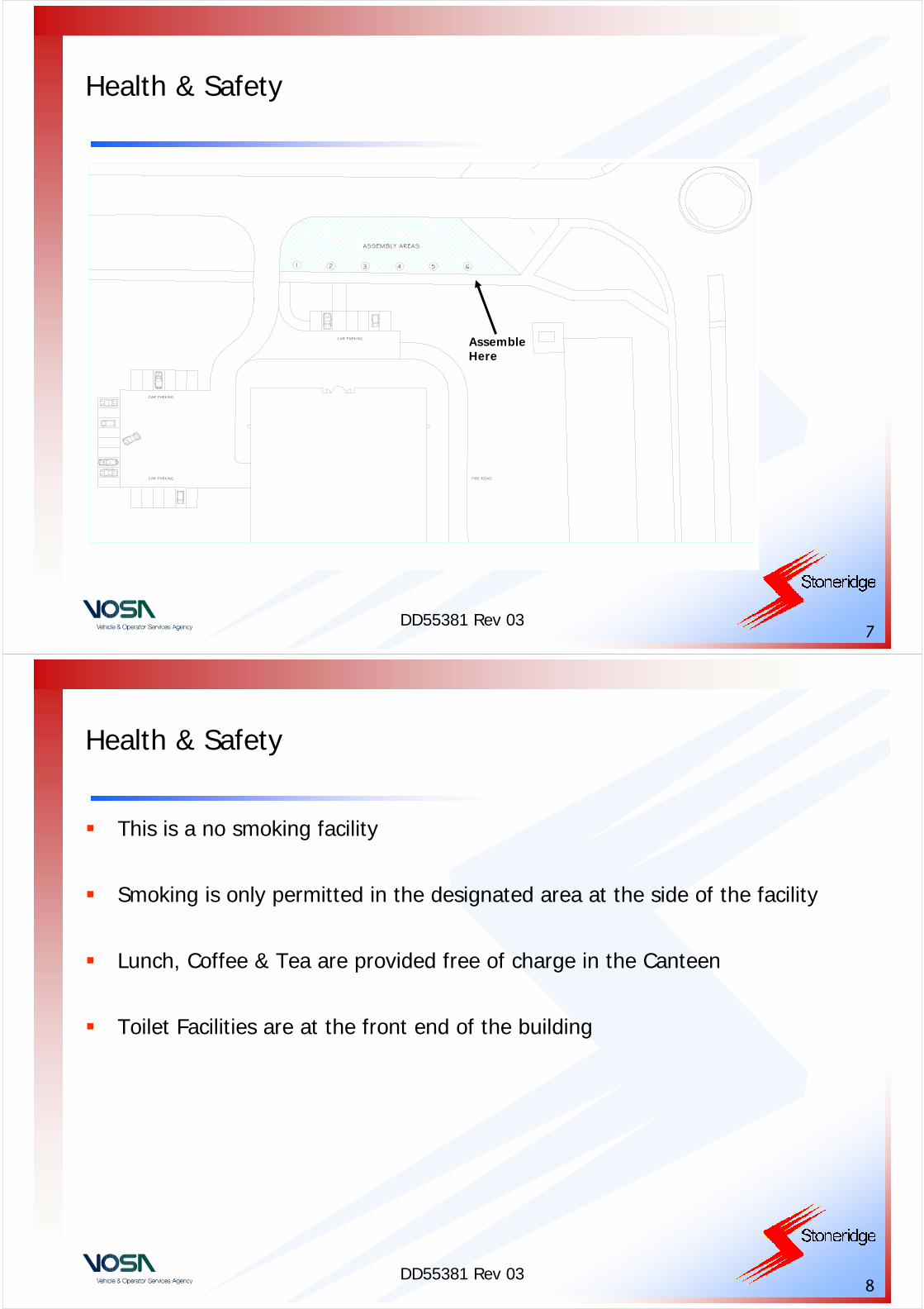
Health & Safety
CAR PARKING
CAR PARKING
CAR PARKING
FIRE ROAD
1 2 3 4 5 6
ASSEMBLY AREAS
Assemble Here
DD55381 Rev 038
Health & Safety
This is a no smoking facility
Smoking is only permitted in the designated area at the side of the facility
Lunch, Coffee & Tea are provided free of charge in the Canteen
Toilet Facilities are at the front end of the building
DD55381 Rev 039
Section 2
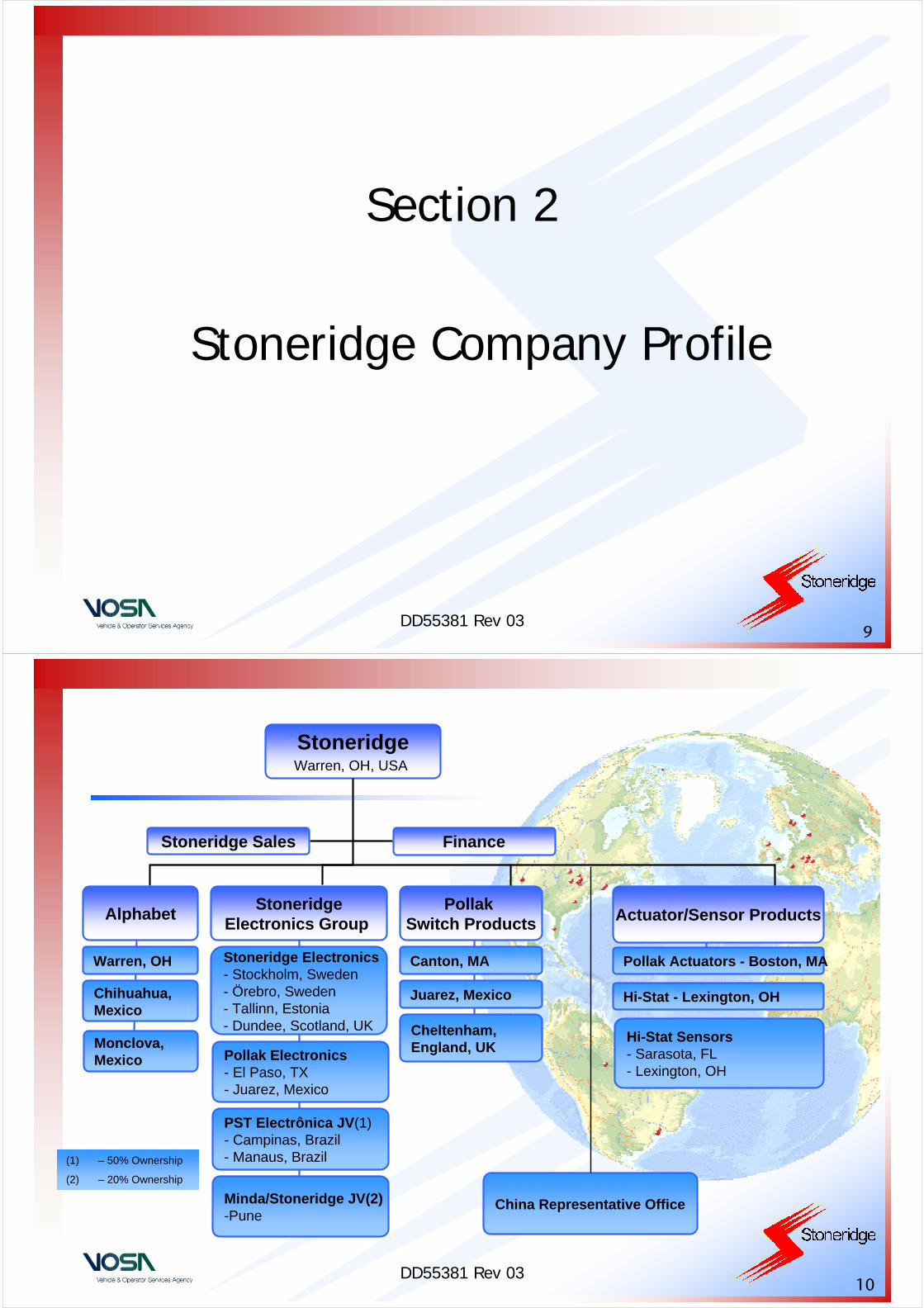
Stoneridge Company Profile
DD55381 Rev 0310
(1) – 50% Ownership
(2) – 20% Ownership
AlphabetStoneridge
Electronics Group Actuator/Sensor Products
Finance
StoneridgeWarren, OH, USA
Chihuahua,Mexico
Warren, OH Stoneridge Electronics- Stockholm, Sweden- Örebro, Sweden- Tallinn, Estonia- Dundee, Scotland, UK
Pollak Electronics- El Paso, TX- Juarez, Mexico
PST Electrônica JV(1)- Campinas, Brazil- Manaus, Brazil
Minda/Stoneridge JV(2)-Pune
Canton, MA
Juarez, Mexico
Cheltenham, England, UK
Pollak Actuators - Boston, MA
Hi-Stat - Lexington, OH
Hi-Stat Sensors- Sarasota, FL- Lexington, OH
Pollak Switch Products
Stoneridge Sales
China Representative Office
Monclova,Mexico

DD55381 Rev 0311
Stoneridge Electronics Locations
Sales & Support:
Stuttgart, Germany Frankfurt, GermanyNuremberg, Germany Madrid, SpainParis, FranceBayonne, France
Dundee, Scotland Örebro, Sweden Bromma, Sweden Tallinn, Estonia
DD55381 Rev 0312
UK – Design, Manufacture & Sales
• Dundee• 100+ employees• 7400 m²
DD55381 Rev 0313
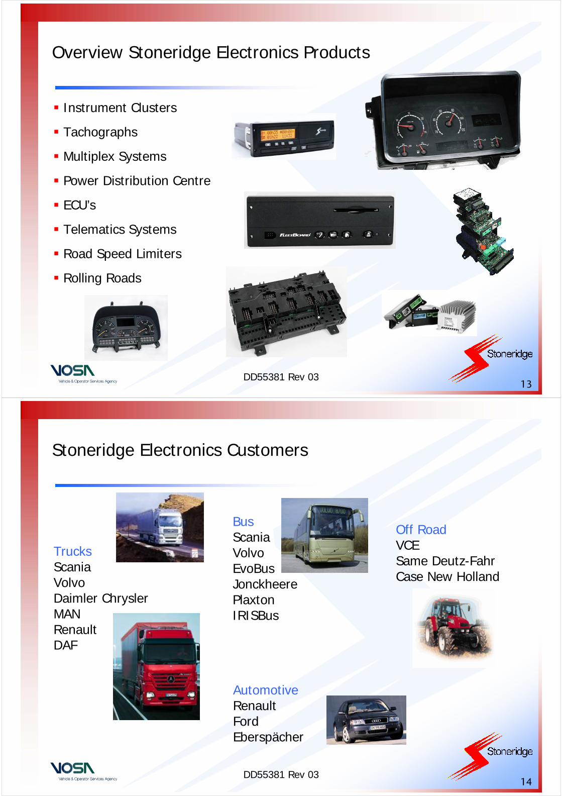
Overview Stoneridge Electronics Products
Instrument Clusters
Tachographs
Multiplex Systems
Power Distribution Centre
ECU’s
Telematics Systems
Road Speed Limiters
Rolling Roads
DD55381 Rev 0314
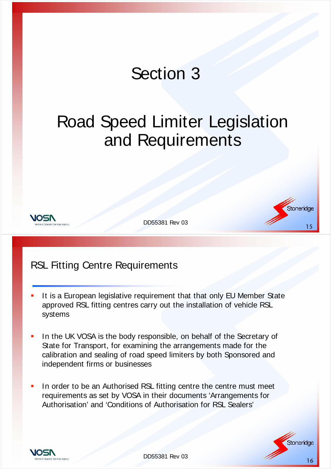
Stoneridge Electronics Customers
Off RoadVCESame Deutz-FahrCase New Holland
BusScaniaVolvoEvoBusJonckheere PlaxtonIRISBus
TrucksScaniaVolvo Daimler ChryslerMANRenault DAF
AutomotiveRenaultFordEberspächer
DD55381 Rev 0315
Section 3
Road Speed Limiter Legislation and Requirements
DD55381 Rev 0316
RSL Fitting Centre Requirements
It is a European legislative requirement that that only EU Member State approved RSL fitting centres carry out the installation of vehicle RSL systems
In the UK VOSA is the body responsible, on behalf of the Secretary of State for Transport, for examining the arrangements made for thecalibration and sealing of road speed limiters by both Sponsored and independent firms or businesses
In order to be an Authorised RSL fitting centre the centre must meet requirements as set by VOSA in their documents ‘Arrangements for Authorisation’ and ‘Conditions of Authorisation for RSL Sealers’
DD55381 Rev 0317
RSL Fitting Centre Requirements
For sponsored Authorised Sealers, the sponsor is responsible for the provision of suitable equipment and the training of the Authorised Sealer and for monitoring the quality of the calibration and sealing work undertaken by their agents
The sponsor also has a responsibility to the sponsored Authorised Sealer with regard to the following:
• To issue a unique seal number or code
• To ensure the agent has the appropriate calibration and sealing equipment for the speed limiter make concerned
• To be responsible for arranging quality assurance checks
DD55381 Rev 0318
RSL Fitting Centre Requirements – Staff Training & Equipment
Only Authorised Sealer staff who have received training considered appropriate by the VOSA are to be permitted to seal RSL systems
Sufficient equipment must be available to Authorised Sealer staff, to allow them to calibrate and seal, in a static condition, each make of speed limiter which they are authorised to seal. Test equipment will be calibrated in accordance with the equipment manufacturer’s instructions and records of such calibration checks will be retained for inspection as necessary
Arrangements must be made to ensure the safe custody of speed limiter sealing equipment, i.e. sealing pliers, seals and plaques and “plates”, when not in use
The sealing pliers will have a unique seal code that shall be applied to all RSL seals or other sealing devices to identify the Authorised Sealer
DD55381 Rev 0319
RSL Fitting Centre Requirements – Records
A register of road speed limiters sealed will be kept. This could be a file of speed limiter installation/calibration records. The register will show the following details:
– Date of sealing (and location if approved as mobile Authorised Sealer)– Vehicle VIN/Chassis Number, Make and Model– Brief description of work carried out e.g. installation, calibration or repair– Set speed (mph or kph)– Tyre sizes (and ‘W’ factor of Tachograph if it is supplying the speed limiter
signal)– Make of speed limiter– Serial number of the ECU or the calibrated speed controlling device– Name and signature of sealing fitter– Unique Authorised Sealer code, trading name and address
Note: Authorised Sealer documentation will be retained and available for at least 5 years from the date when the speed limiter work was undertaken
DD55381 Rev 0320
RSL Fitting Centre Requirements –Access to Premises & Quality Assurance
VOSA Examiners will be permitted, on production of their authority if so required, during normal business hours, to examine the register, to inspect the equipment and to satisfy themselves that the Conditions of Authorisation are being complied with
If the Authority of a Fitting Centre to Seal RSL systems in withdrawn by VOSA or if the Centre ceases to operate, then the Centre MUST surrender all RSL sealing equipment and “plates” to the Sponsor
VOSA Authorised Sealers must have their operation to be independently monitored for quality assurance. A Sponsored Authorised Sealer’s quality assurance monitoring may be performed by the Sponsoring speed limiter manufacturer or an agent nominated by him. In the case of independent Authorised Sealer, quality assurance monitoring will be performed by an independent agent nominated by him
The quality assurance inspection must check that all the Conditions of Authorisation are being complied with
The maximum period between quality checks will be 18 months. As a minimum the check will ascertain whether all the Conditions of Authorisation are being complied with

DD55381 Rev 0321
RSL Vehicle Legislation - Initial PCV Legislation
The first speed limiter law in the UK applied only to Coaches, defined as vehicles with more than 16 passenger seats, as follows:
• Coaches registered on or after 01/04/1974, but before 01/01/1988must be fitted with an RSL set at 112.65 km/h (70mph)
Buses, defined as vehicles with more than 8 passenger seats, that have a gross vehicle weight of 7501 Kg or greater have speed limiter restrictions as follows:
• Provided the buses were registered between the inclusive dates of 01/01/1988 and 30/09/2001 they must be fitted with an RSL set at100 km/h
All Buses and Coaches that were registered before 01/04/1974 DO NOT require a RSL system to be fitted
DD55381 Rev 0322
RSL Vehicle Legislation – Initial HGV Requirements
Goods vehicles that have a gross vehicle weight of 12001 Kg or greater and that are capable of exceeding a speed of 90 km/h, have speedlimiter restrictions as follows:
• Provided the vehicles were registered between the inclusive dates of 01/01/1988 and 30/09/2001 they must be fitted with an RSL set such that the vehicles stabilised speed does not exceed 90 km/h
All Goods vehicles of any gross weight, that were registered before 01/01/1988 DO NOT require a Road Speed Limiter system to be fitted
DD55381 Rev 0323
RSL Vehicle Legislation – 92/6/EEC Changes
EU Council Directive 92/6/EEC, which was adopted on 10/02/1992, requires that Goods Vehicles that have a gross vehicle weight of 7501 Kg to less than 12001 Kg and that are capable of exceeding a speed of 96 km/h have speed limiter restrictions as follows:
• Provided the vehicles were registered between the inclusive dates of on or after 01/08/1992 to 30/09/2001 they must be fitted with an RSL set such that the vehicles stabilised speed does not exceed 96 km/h
All Goods vehicles with a gross weight of 7501 Kg to less than 12001 Kg that were registered before 01/08/1992 AND All goods vehicles with a gross weight of 3501 Kg to less than 7501 Kg that were registered before 01/10/2001 DO NOT require a Road Speed Limiter system to be fitted
DD55381 Rev 0324
RSL Vehicle Legislation – 2002/85/EC Changes
EU Council Directive 2002/85/EC, which amends Council Directive 92/6/EEC and which was adopted on 05/11/2002 had a great impact on speed limiter requirements with regard to Passenger Carrying Vehicles and Goods Vehicles
In terms of buses, the changes are as follows:
• All PCV’s with a Gross weight of 7501 Kg to less than 10001 Kg and that were registered on or after 01/10/2001 AND all PCV’s with a gross weight of 10001 Kg or greater and that were registered on or after 01/01/2005 must be fitted with an RSL set such that the vehicles stabilised speed does not exceed 100 km/h
DD55381 Rev 0325
RSL Vehicle Legislation – 2002/85/EC Changes
• PCV’s with a Gross weight of less than 7501 Kg and a Euro III or later engine and that were registered on or after 01/10/2001 but before 01/01/2005 must be fitted with an RSL set such that the vehiclesstabilised speed does not exceed 100 km/h. The RSL must be fitted by 01/01/2006 for international journeys and by 01/01/2007 for UK national journeys. Note: Vehicles registered before 01/01/2005 with a Euro II or earlier diesel and petrol engines are exempt from this requirement
• All PCV’s, except note below, regardless of Gross weight and engine type, that were registered on or after 01/01/2005 must be fitted for all journeys with an RSL set such that the vehicles stabilised speed does not exceed 100 km/hNote: For PCV’s with a gross weight that does not exceed 5000 Kg, that are used for UK national journeys only, the RSL requirement is active only from 01/01/2008
DD55381 Rev 0326
RSL Vehicle Legislation – 2002/85/EC Changes
In terms of Goods Vehicles the RSL laws and changes are as follows:
• All HGV’s with a Gross weight of 12001 Kg or more and that were registered on or after 01/01/1988 must be fitted with an RSL set such that the vehicles stabilised speed does not exceed 90 km/h
• All HGV’s with a Gross weight of 7501 Kg to less than 12001 Kg and that were registered between 01/08/1992 and 31/12/2004 must be fitted with an RSL set such that the vehicles stabilised speed does not exceed 96 km/h. For vehicles of this type registered on or after 01/01/2005 they must be fitted with an RSL set such that the vehicles stabilised speed does not exceed 90 km/h
DD55381 Rev 0327
RSL Vehicle Legislation – 2002/85/EC Changes
• Goods Vehicles with a Gross weight of 3501 Kg to less than 7501 Kg and a Euro III or later engine and that were registered on or after 01/10/2001 but before 01/01/2005 must be fitted with an RSL set such that the vehicles stabilised speed does not exceed the value 90 km/h
• The RSL must be fitted by 01/01/2006 for international journeys and by 01/01/2007 for UK national journeys
• Note: Vehicles as above with a Euro II or earlier diesel or petrol engine are exempt from this requirement and DO NOT require RSL fitment
DD55381 Rev 0328
RSL Vehicle Legislation – 2002/85/EC Changes
• All Goods Vehicles, except note below, with a Gross weight of 3501 Kg or more, regardless of engine type, that were registered on or after 01/01/2005 must be fitted for all journeys with an RSL set such that the vehicles stabilised speed does not exceed 90 km/h
• Note: For Goods Vehicles with a gross weight of 3501 to less than 7501 Kg, that are used for UK national journeys only, the RSL requirement is only active from 01/01/2008
Please Note that a summary table of the Road Speed Limiter Requirements for all types and ages of Goods Vehicle and Passenger Carrying Vehicles is included as an Appendix
DD55381 Rev 0329
Section 4
The Stoneridge Electronics 9700 Electronic Road Speed Limiter
DD55381 Rev 0330
9700 ERSL System Description & Operation – General Theory
The Stoneridge 9700 Electronic Road Speed Limiter (ERSL) must only be used on vehicles that have an electronic accelerator throttle control that is connected to a vehicle ECU
It must be noted that the Stoneridge 9700 ERSL is not suitable for use on vehicles that use a CANbus based Cruise Control System
If a vehicle allows a Cruise Control switch to set the vehicle Cruise Control speed without reference to the accelerator throttle position then the 9700 ERSL must not be used as a speed limiting device
IN ALL CASES, ONCE A 9700 ERSL IS FITTED INTO A VEHICLE THE VEHICLE MUST BE ROAD TESTED TO ENSURE ROAD SPEED LIMITING FUNCTION IS SUCCESSFUL AT ALL TIMES WHETHER OR NOT AN INDEPENDENT CRUISE CONTROL SYSTEM IS OPERATIONAL
DD55381 Rev 0331
9700 ERSL System Description & Operation – General Theory
An electronic accelerator pedal has no mechanical connection to the vehicle fuel system but has a potentiometer output signal that is proportional to the pedal position. When the pedal is not depressed, the potentiometer output is at the ‘Idle’ voltage level
As the pedal is pressed the potentiometer output increases proportionally to the pedal position until the stage when the pedal is fully depressed and the potentiometer output is at the ‘Wide-open-throttle’ (WOT) voltage level
The Stoneridge 9700 ERSL controller is an electronic ECU that is used to intercept the potentiometer output signals from the accelerator as shown in the diagram later in this section
DD55381 Rev 0332
9700 ERSL System Description & Operation – General Theory
The ERSL controller must receive a known accurate ‘speed’ signal from the vehicle which is used to give an accurate indication of vehicle speed. This is usually from the vehicle Tachograph, which is a legally calibrated instrument, but may be from another vehicle source such as the ABS ECUNote: A Tachograph V-pulse signal can only be used as an ERSL input for Tachograph K-factors in the range 2300 to 59800
The ERSL controller is programmed with a user specified ‘Speed Limit’value, e.g. 90km/h
When the speed of the vehicle, as determined from the legally calibrated Tachograph output signal or equivalent, reaches the set speed limit the ERSL controller adapts the intercepted accelerator output signals and prevents vehicle acceleration
DD55381 Rev 0333
9700 ERSL System Description & Operation – General Theory
The ERSL controller modifies the received accelerator signal in such a way that the modified signal sent to the vehicle ECU replicates an accelerator pedal that is in the correct position for the ERSL set speed
Any further increase in accelerator pedal depression and hence output voltage will be suppressed by the ERSL controller such that a modified potentiometer output signal will be sent to the vehicle ECU and hence the stabilised vehicle speed will remain just below the set ERSL speed limit value
If the vehicle slows down the ERSL controller will slightly increase the modified potentiometer output signal sent to the vehicle ECU and hence keep the vehicle speed at the required ERSL speed limit value
If vehicle pedal is raised such that the position is at a level below the ERSL set limit then the ERSL will pass the accelerator output signal to the vehicle ECU unmodified
DD55381 Rev 0334
9700 ERSL System Description & Operation – General Theory
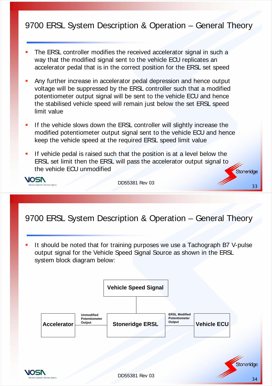
It should be noted that for training purposes we use a Tachograph B7 V-pulse output signal for the Vehicle Speed Signal Source as shown in the ERSL system block diagram below:
Vehicle ECUStoneridge ERSLAccelerator
Unmodified Potentiometer Output
ERSL Modified Potentiometer Output
Vehicle Speed Signal
DD55381 Rev 0335
9700 ERSL System Description & Operation – Connections
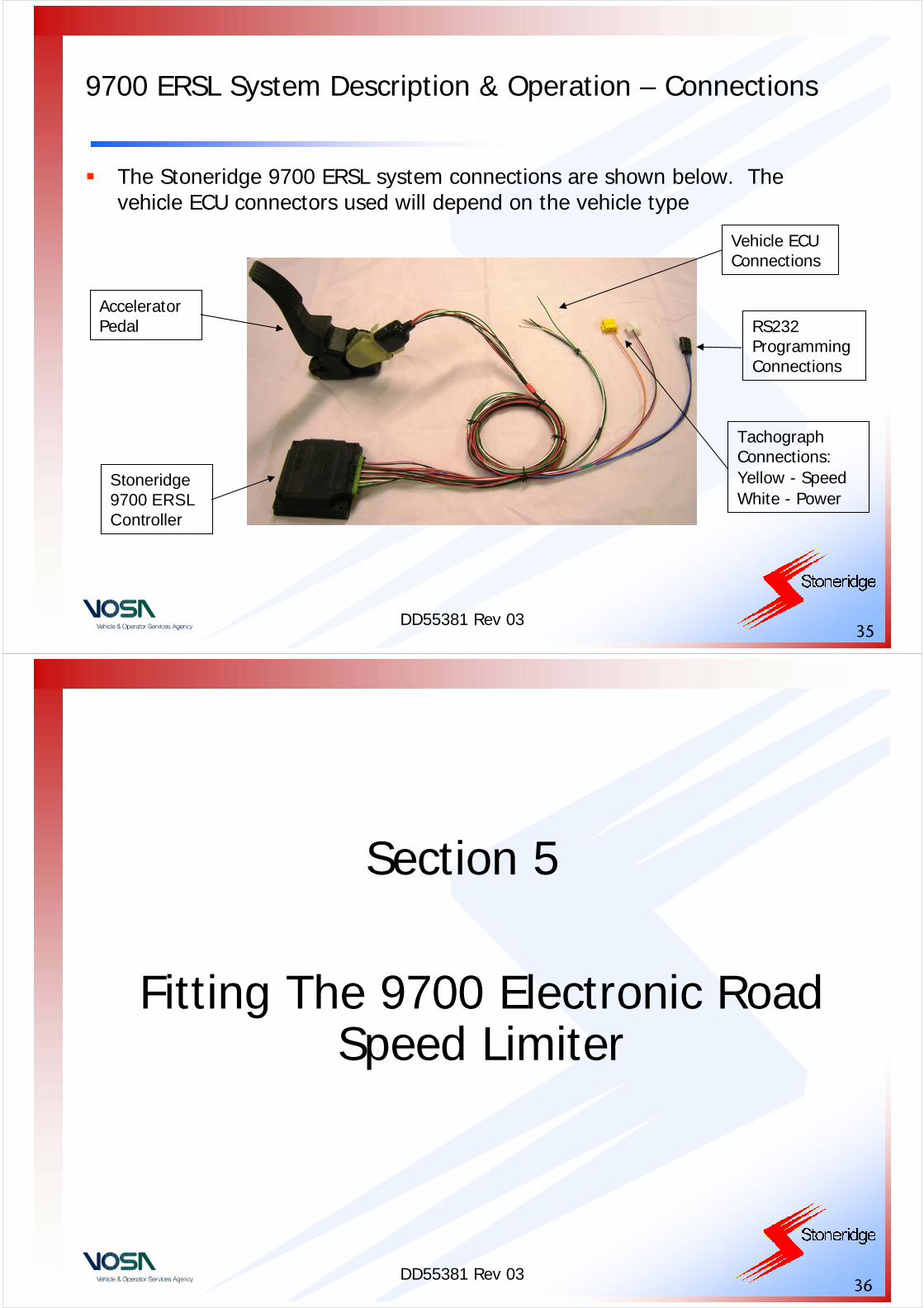
The Stoneridge 9700 ERSL system connections are shown below. The vehicle ECU connectors used will depend on the vehicle type
Accelerator Pedal
Stoneridge 9700 ERSL Controller
Vehicle ECU Connections
Tachograph Connections:Yellow - SpeedWhite - Power
RS232 Programming Connections
DD55381 Rev 0336
Section 5
Fitting The 9700 Electronic Road Speed Limiter
DD55381 Rev 0337
Fitting the 9700 ERSL System – 9700 Controller Inspection
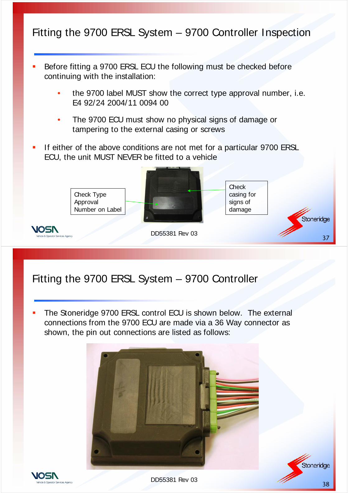
Before fitting a 9700 ERSL ECU the following must be checked before continuing with the installation:
• the 9700 label MUST show the correct type approval number, i.e. E4 92/24 2004/11 0094 00
• The 9700 ECU must show no physical signs of damage or tampering to the external casing or screws
If either of the above conditions are not met for a particular 9700 ERSL ECU, the unit MUST NEVER be fitted to a vehicle
Check Type Approval Number on Label
Check casing for signs of damage
DD55381 Rev 0338
Fitting the 9700 ERSL System – 9700 Controller
The Stoneridge 9700 ERSL control ECU is shown below. The external connections from the 9700 ECU are made via a 36 Way connector asshown, the pin out connections are listed as follows:
DD55381 Rev 0339
Fitting the 9700 ERSL System – 9700 Controller Pin Connections
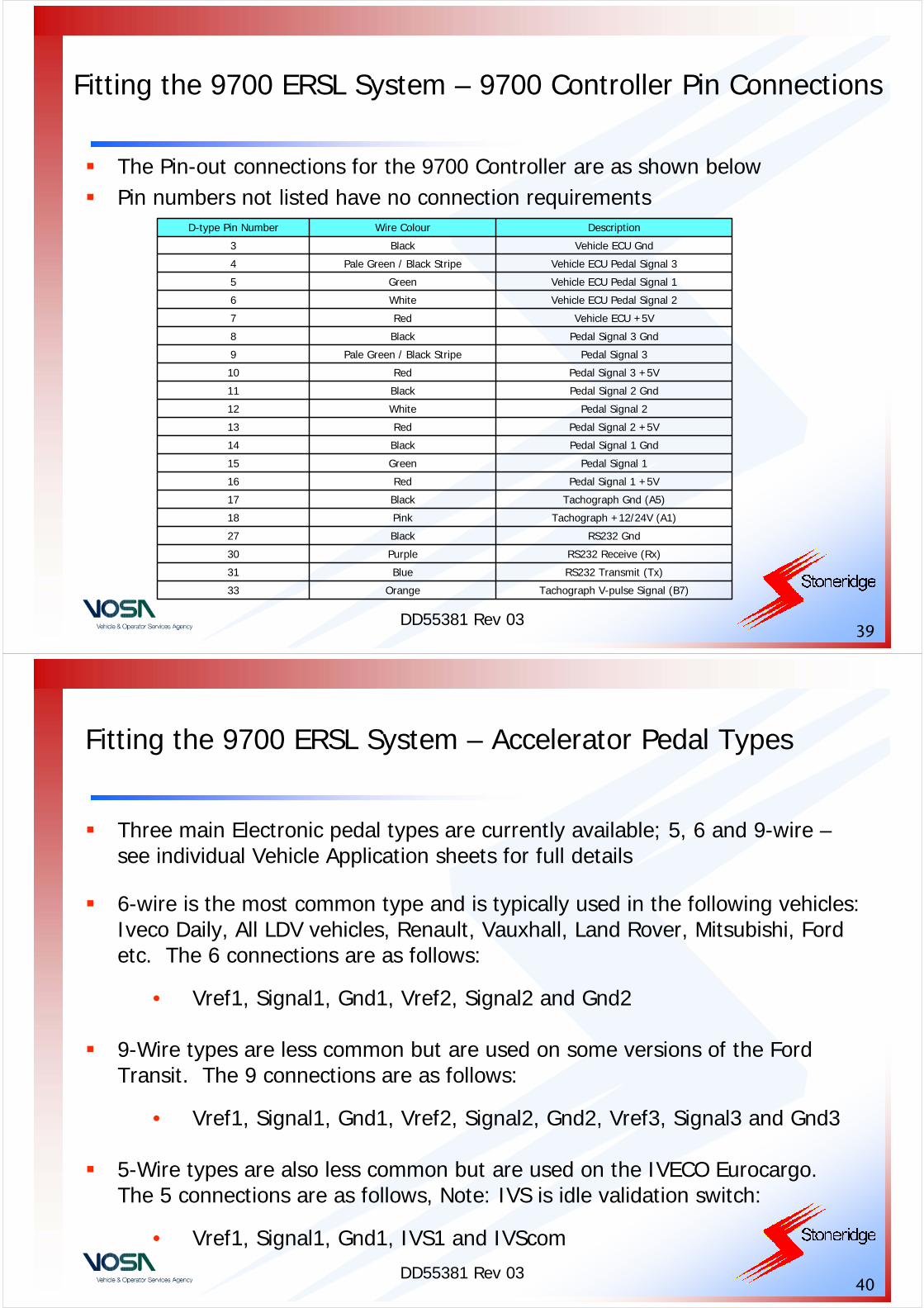
RS232 Receive (Rx)Purple30
Tachograph +12/24V (A1)Pink18
RS232 GndBlack27
RS232 Transmit (Tx)Blue31
Tachograph V-pulse Signal (B7)Orange33
Tachograph Gnd (A5)Black17
Pedal Signal 1 +5VRed16
Pedal Signal 1Green15
Pedal Signal 1 GndBlack14
Pedal Signal 2 +5VRed13
Pedal Signal 2White12
Pedal Signal 2 GndBlack11
Pedal Signal 3 +5VRed10
Pedal Signal 3Pale Green / Black Stripe9
Pedal Signal 3 GndBlack8
Vehicle ECU +5VRed7
Vehicle ECU Pedal Signal 2White6
Vehicle ECU Pedal Signal 1Green5
Vehicle ECU Pedal Signal 3Pale Green / Black Stripe4
Vehicle ECU GndBlack3
DescriptionWire ColourD-type Pin Number
The Pin-out connections for the 9700 Controller are as shown below Pin numbers not listed have no connection requirements
DD55381 Rev 0340
Fitting the 9700 ERSL System – Accelerator Pedal Types
Three main Electronic pedal types are currently available; 5, 6 and 9-wire –see individual Vehicle Application sheets for full details
6-wire is the most common type and is typically used in the following vehicles: Iveco Daily, All LDV vehicles, Renault, Vauxhall, Land Rover, Mitsubishi, Ford etc. The 6 connections are as follows:
• Vref1, Signal1, Gnd1, Vref2, Signal2 and Gnd2
9-Wire types are less common but are used on some versions of the Ford Transit. The 9 connections are as follows:
• Vref1, Signal1, Gnd1, Vref2, Signal2, Gnd2, Vref3, Signal3 and Gnd3
5-Wire types are also less common but are used on the IVECO Eurocargo. The 5 connections are as follows, Note: IVS is idle validation switch:
• Vref1, Signal1, Gnd1, IVS1 and IVScom
DD55381 Rev 0341
Fitting the 9700 ERSL System – Wiring the Accelerator Pedal
Once the type of accelerator pedal fitted into the vehicle has been identified the connections to the pedal must be identified in order to determine which of the 9700 controller connections should be made
If a Stoneridge ERSL Application Sheet is available for the Vehicle type being fitted with the 9700 ERSL ECU then the Application sheet should be used for a description of wiring instructions and fitting instructions etc
If no application sheet is available for the vehicle type into which the 9700 ERSL is to be fitted, then a multi-meter capable of measuring DC voltage and carrying out resistance and continuity measurements should be used to determine the pedal connections using the method as described below:
DD55381 Rev 0342
Fitting the 9700 ERSL System – Wiring the Accelerator Pedal
To identify ‘Vref’ signal, set vehicle ignition to ON and multi-meter to the DC voltage setting, 0-20V range
• Connect multi-meter negative terminal to vehicle battery negative and probe accelerator pedal wires with the multi-meter positive terminal
• All the pedal ‘Vref’ signals, 3 maximum, will be fixed at +5V
To identify the ‘Gnd’ signal wire, switch vehicle ignition OFF and disconnect the vehicle battery positive terminal. Set the multi-meter to the resistance setting, 0-200R
• The ‘Gnd’ signal wires will have a very low resistance to the battery negative terminal
DD55381 Rev 0343
Fitting the 9700 ERSL System – Wiring the Accelerator Pedal
To identify ‘Vref’ and ‘Gnd’ signal pairs, switch vehicle ignition OFF. Disconnect the vehicle battery positive terminal and the pedal connections to the vehicle ECU. Set the multi-meter to a resistance setting, 20K range
• Connect multi-meter negative to a known pedal signal ‘Gnd’ wire
• The known ‘Vref’ signal wires should be probed until a resistance reading of typically a few Kilo-ohms is shown on the multi-meter to match up with the known signal ‘Gnd’ connection under test
• Repeat process until all the ‘Vref’ and ‘Gnd’ connections have been matched up
DD55381 Rev 0344
Fitting the 9700 ERSL System – Wiring the Accelerator Pedal
To identify pedal signal wires, switch vehicle ignition OFF. Disconnect the vehicle battery positive terminal and the pedal connections to the vehicle ECU. Set the multi-meter to a resistance setting, 20K range
• Connect multi-meter negative to a known pedal signal ‘Gnd’ wire
• The known Pedal signal wires should be probed until a resistancereading of typically 2K to 5K is shown on the multi-meter to match up with the known signal ‘Gnd’ connection under test
• Repeat process until all the ‘Pedal Signal’ and ‘Gnd’ connections have been matched up
DD55381 Rev 0345
Fitting the 9700 ERSL System – Wiring the Accelerator Pedal
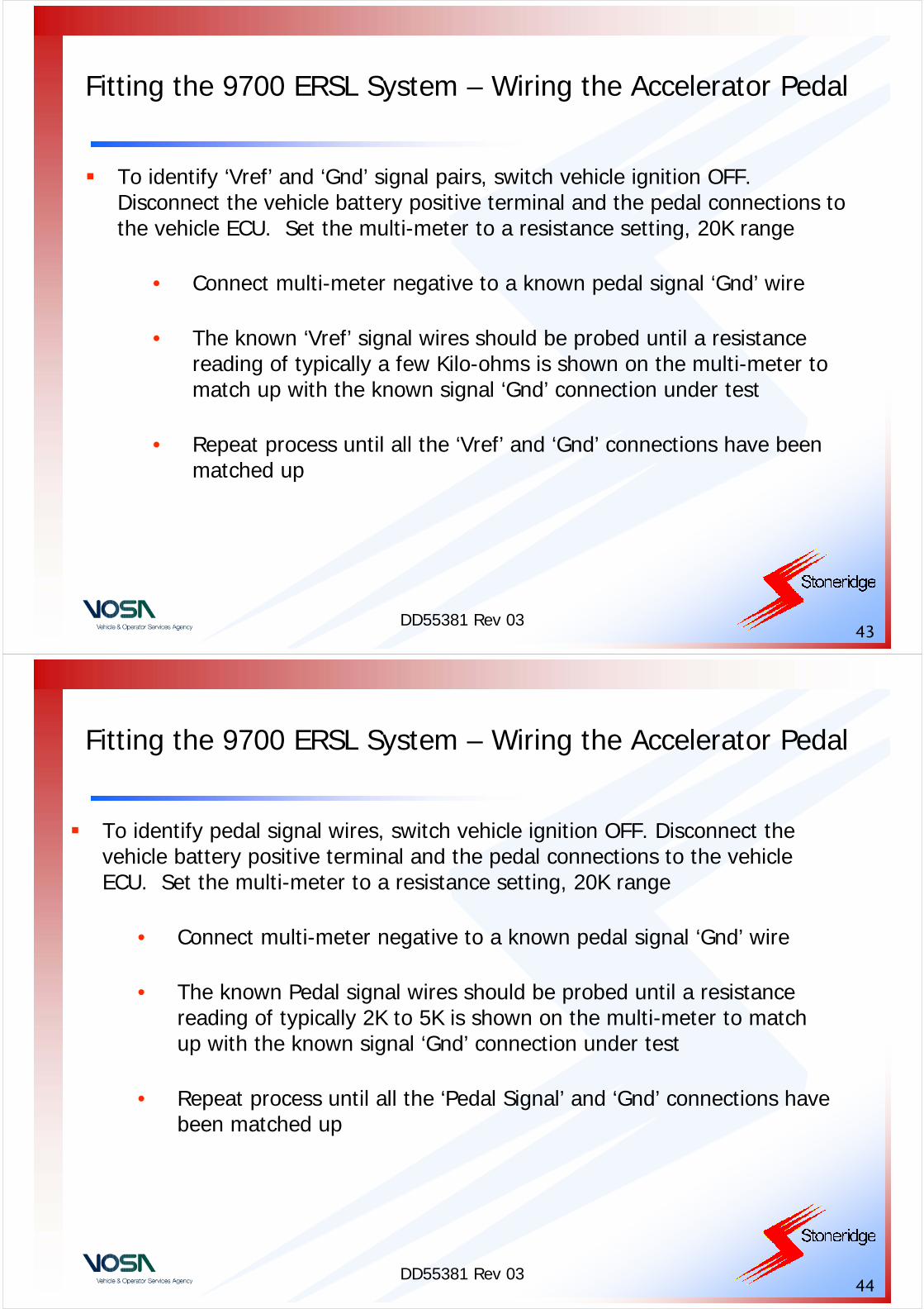
Once all the accelerator pedal wire functions have been identified, next the existing pedal-vehicle ECU wires must be cut so that the 9700 ERSL ECU can be wired using the 9700 pin-out connections listed above
All of the in-line connections made to the pedal, vehicle ECU and the 9700 (including unused wires) must be placed in black sealing boxes, 6955-596, in a similar manner to that shown below. The sealing boxes should be secured using Tachograph sealing wire and a suitably marked VOSA approved seal again similarly to as shown below
DD55381 Rev 0346
Fitting the 9700 ERSL System – Mounting the 9700 Controller
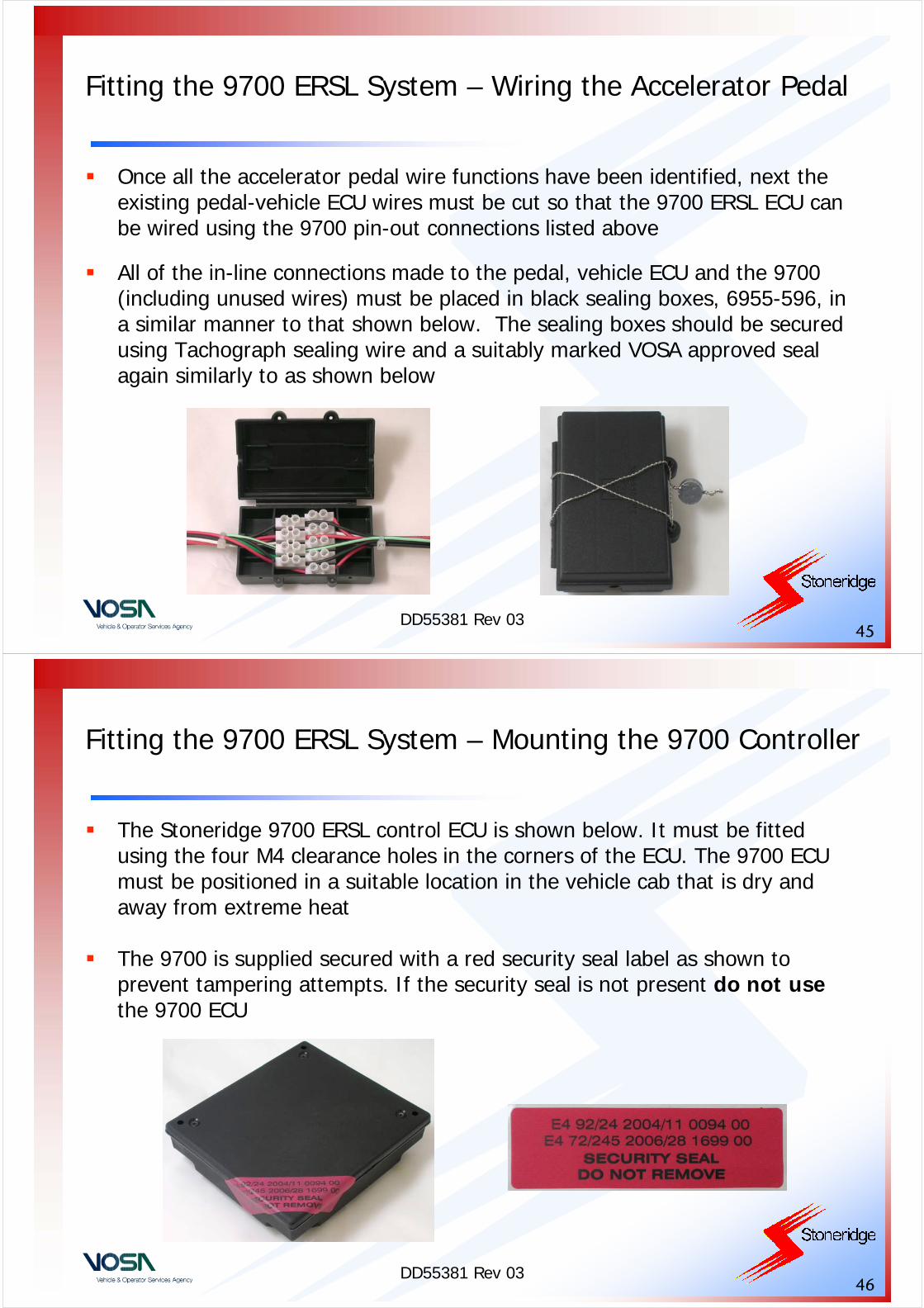
The Stoneridge 9700 ERSL control ECU is shown below. It must be fitted using the four M4 clearance holes in the corners of the ECU. The 9700 ECU must be positioned in a suitable location in the vehicle cab that is dry and away from extreme heat
The 9700 is supplied secured with a red security seal label as shown to prevent tampering attempts. If the security seal is not present do not usethe 9700 ECU

DD55381 Rev 0347
Fitting the 9700 ERSL System – Securing the 9700 ECU Connections
The Stoneridge 9700 ERSL control ECU connections should be secured using a sealing shroud as shown below. The shroud itself should be secured using Tachograph sealing wire and a suitably marked VOSA approved seal. Note: it MUST be ensured that the connector cannot be removed without first breaking the seal
Connector Before Sealing Connector Fitted
and Sealed
DD55381 Rev 0348
Fitting the 9700 ERSL System – RSL Plaques
Once the Stoneridge 9700 ERSL ECU has been fully fitted into the vehicle and calibrated and programmed as per the next section, a RSL plaque must be fitted inside the vehicle. The plaque, examples shown below, must be clearly visible and easily accessible, and must contain the following details:
• Date of RSL calibration
• RSL Fitting Station Address
• Name of the Technician Who Fitted the RSL
DD55381 Rev 0349
Section 6
Calibrating and Programming The 9700 Electronic Road Speed Limiter
DD55381 Rev 0350
Calibrating the 9700 ERSL System – Executing the PC Software
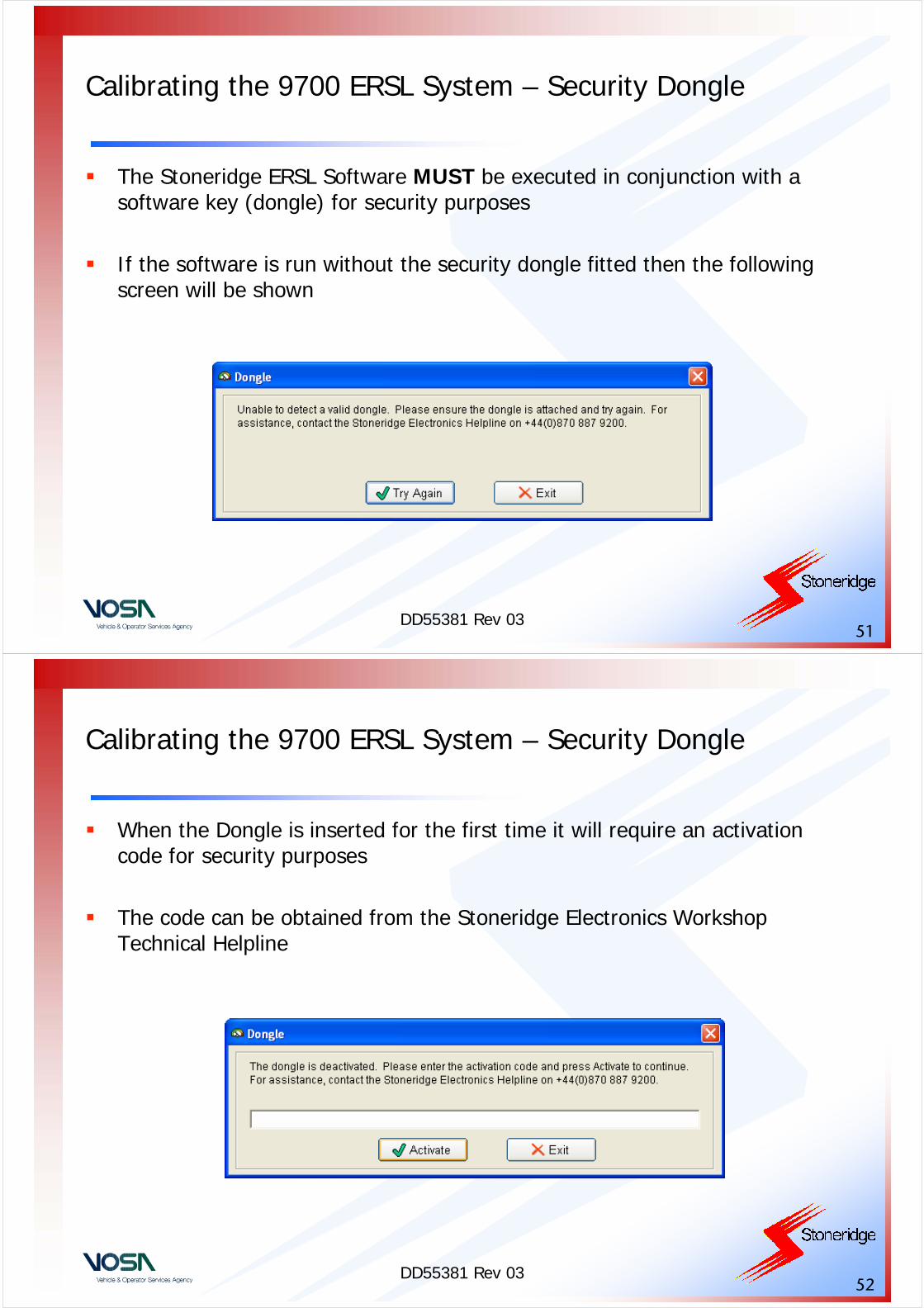
The Stoneridge 9700 ERSL control ECU software is ‘run’ on the PC by clicking on the ‘ERSL’ Icon on the PC desktop
The first time the software is ‘run’ after installation, there will be no default language set. Select the required flag as shown below for English, Swedish, German, Spanish, Italian or French as the default language
DD55381 Rev 0351
Calibrating the 9700 ERSL System – Security Dongle
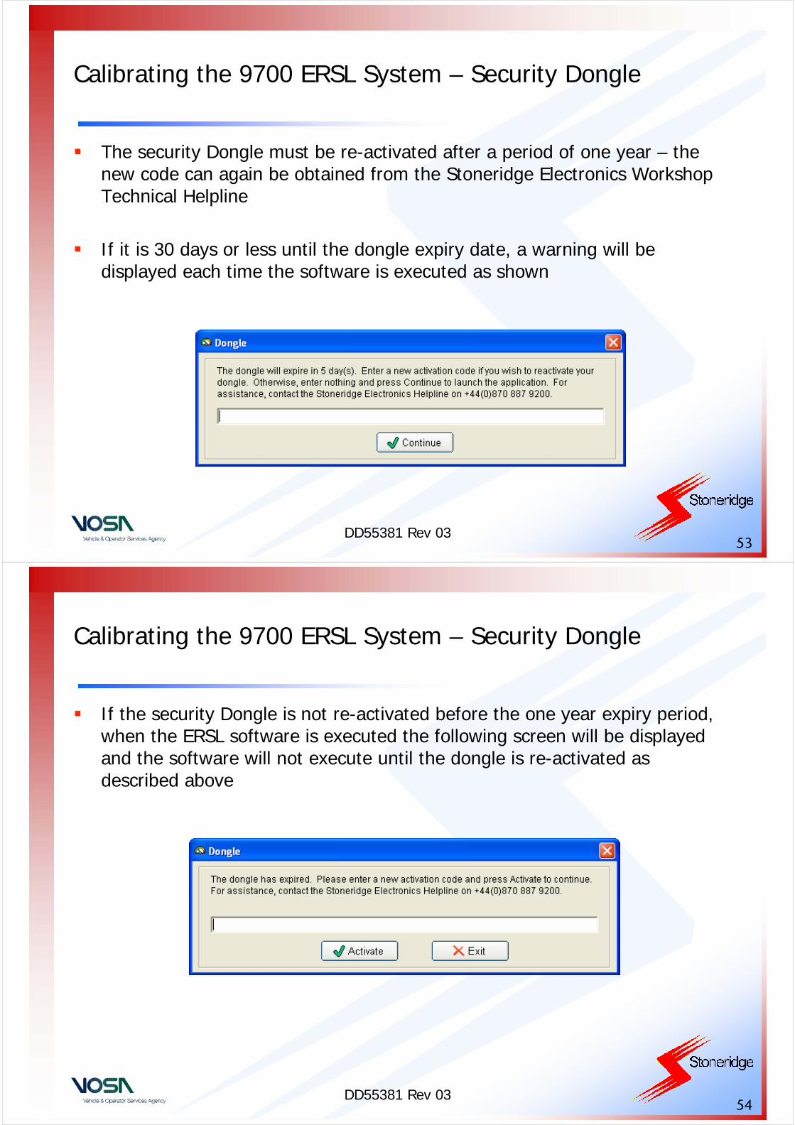
The Stoneridge ERSL Software MUST be executed in conjunction with a software key (dongle) for security purposes
If the software is run without the security dongle fitted then the following screen will be shown
DD55381 Rev 0352
Calibrating the 9700 ERSL System – Security Dongle
When the Dongle is inserted for the first time it will require an activation code for security purposes
The code can be obtained from the Stoneridge Electronics Workshop Technical Helpline
DD55381 Rev 0353
Calibrating the 9700 ERSL System – Security Dongle
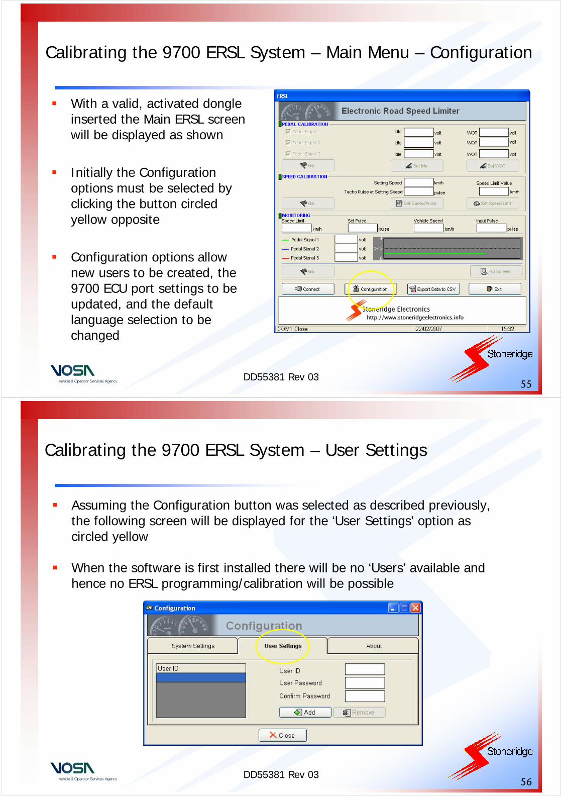
The security Dongle must be re-activated after a period of one year – the new code can again be obtained from the Stoneridge Electronics Workshop Technical Helpline
If it is 30 days or less until the dongle expiry date, a warning will be displayed each time the software is executed as shown
DD55381 Rev 0354
Calibrating the 9700 ERSL System – Security Dongle
If the security Dongle is not re-activated before the one year expiry period, when the ERSL software is executed the following screen will be displayed and the software will not execute until the dongle is re-activated as described above
DD55381 Rev 0355
Calibrating the 9700 ERSL System – Main Menu – Configuration
With a valid, activated dongle inserted the Main ERSL screen will be displayed as shown
Initially the Configuration options must be selected by clicking the button circled yellow opposite
Configuration options allow new users to be created, the 9700 ECU port settings to be updated, and the default language selection to be changed
DD55381 Rev 0356
Calibrating the 9700 ERSL System – User Settings
Assuming the Configuration button was selected as described previously, the following screen will be displayed for the ‘User Settings’ option as circled yellow
When the software is first installed there will be no ‘Users’ available and hence no ERSL programming/calibration will be possible
DD55381 Rev 0357
Calibrating the 9700 ERSL System – Adding Users
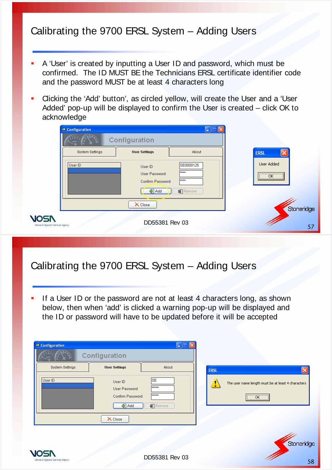
A ‘User’ is created by inputting a User ID and password, which must be confirmed. The ID MUST BE the Technicians ERSL certificate identifier code and the password MUST be at least 4 characters long
Clicking the ‘Add’ button’, as circled yellow, will create the User and a ‘User Added’ pop-up will be displayed to confirm the User is created – click OK to acknowledge
DD55381 Rev 0358
Calibrating the 9700 ERSL System – Adding Users
If a User ID or the password are not at least 4 characters long, as shown below, then when ‘add’ is clicked a warning pop-up will be displayed and the ID or password will have to be updated before it will be accepted
DD55381 Rev 0359
Calibrating the 9700 ERSL System – Adding Users
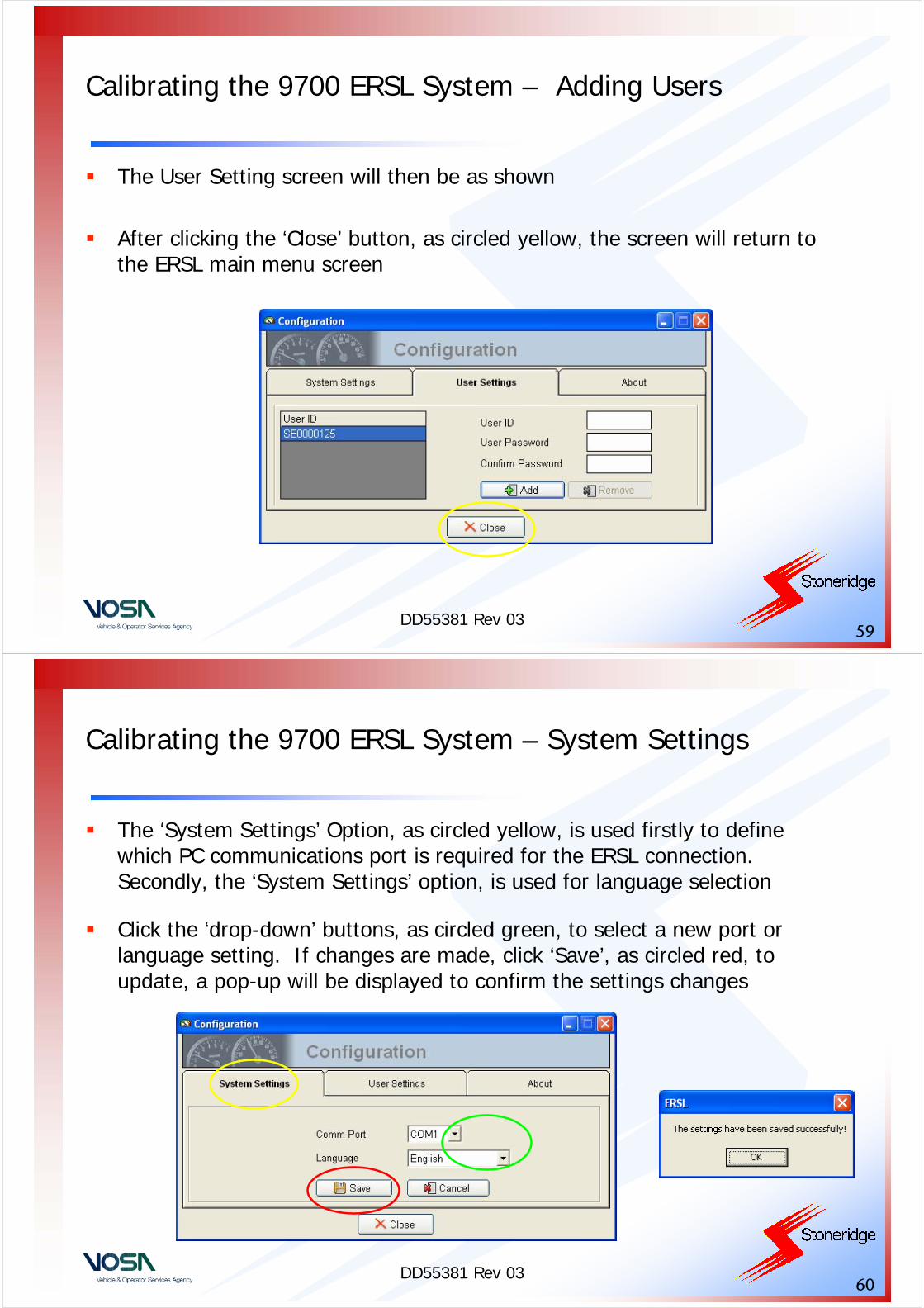
The User Setting screen will then be as shown
After clicking the ‘Close’ button, as circled yellow, the screen will return to the ERSL main menu screen
DD55381 Rev 0360
Calibrating the 9700 ERSL System – System Settings
The ‘System Settings’ Option, as circled yellow, is used firstly to define which PC communications port is required for the ERSL connection. Secondly, the ‘System Settings’ option, is used for language selection
Click the ‘drop-down’ buttons, as circled green, to select a new port or language setting. If changes are made, click ‘Save’, as circled red, to update, a pop-up will be displayed to confirm the settings changes
DD55381 Rev 0361
Calibrating the 9700 ERSL System – Connecting the 9700 ECU
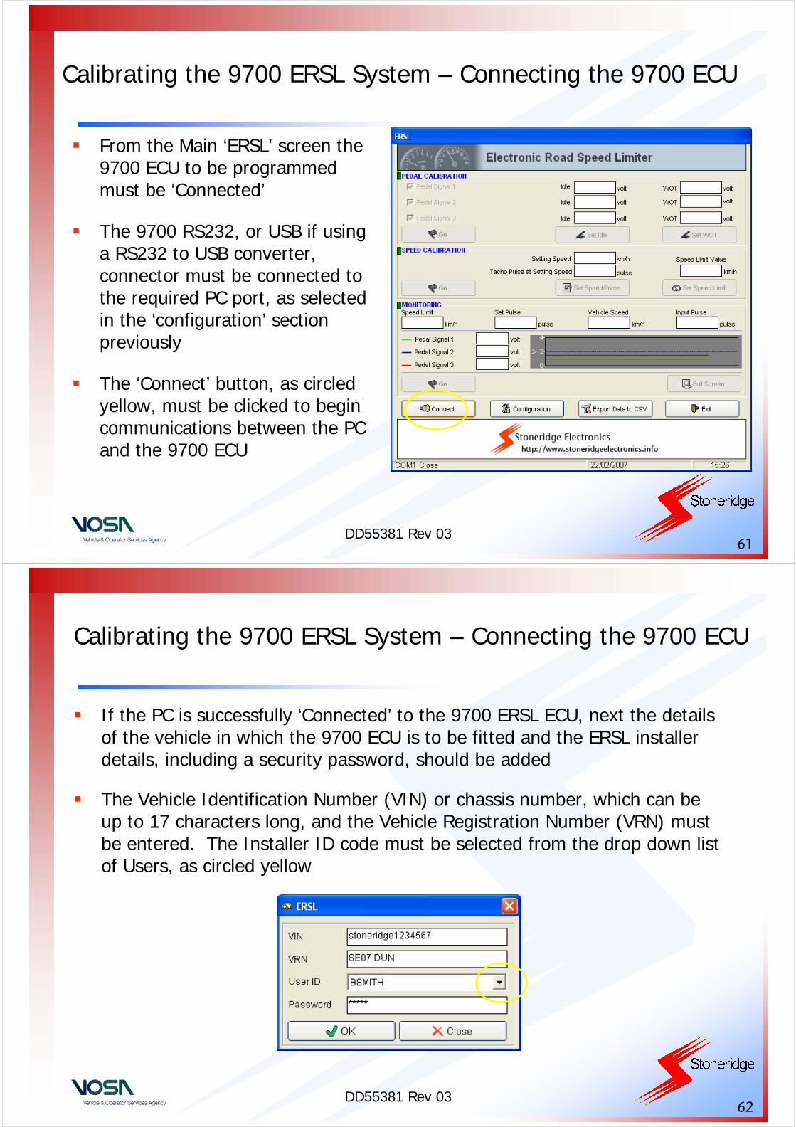
From the Main ‘ERSL’ screen the 9700 ECU to be programmed must be ‘Connected’
The 9700 RS232, or USB if using a RS232 to USB converter, connector must be connected to the required PC port, as selected in the ‘configuration’ section previously
The ‘Connect’ button, as circled yellow, must be clicked to begin communications between the PC and the 9700 ECU
DD55381 Rev 0362
Calibrating the 9700 ERSL System – Connecting the 9700 ECU
If the PC is successfully ‘Connected’ to the 9700 ERSL ECU, next the details of the vehicle in which the 9700 ECU is to be fitted and the ERSL installer details, including a security password, should be added
The Vehicle Identification Number (VIN) or chassis number, which can be up to 17 characters long, and the Vehicle Registration Number (VRN) must be entered. The Installer ID code must be selected from the drop down list of Users, as circled yellow
DD55381 Rev 0363
Calibrating the 9700 ERSL System – Connecting the 9700 ECU
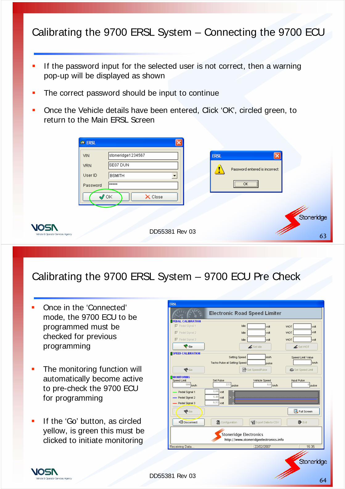
If the password input for the selected user is not correct, then a warning pop-up will be displayed as shown
The correct password should be input to continue
Once the Vehicle details have been entered, Click ‘OK’, circled green, to return to the Main ERSL Screen
DD55381 Rev 0364
Calibrating the 9700 ERSL System – 9700 ECU Pre Check
Once in the ‘Connected’mode, the 9700 ECU to be programmed must be checked for previous programming
The monitoring function will automatically become active to pre-check the 9700 ECU for programming
If the ‘Go’ button, as circled yellow, is green this must be clicked to initiate monitoring

DD55381 Rev 0365
Calibrating the 9700 ERSL System – 9700 ECU Pre Check
The pre-check will begin as indicated by the ‘Monitoring’green light being active, as circled red
The ‘Speed Limit’ programmed (if any), the ‘Set Pulse’ level and the pedal signal levels, as circled yellow, can then be checked
DD55381 Rev 0366
Calibrating the 9700 ERSL System – Pedal Calibration
Once vehicle and installer details have been input and the pre-check has been completed, the ‘Pedal Calibration’ operations must then be carried out
Pedal Calibration will initially begin automatically. The ‘GO’button, as circled yellow, is not active until the Pedal calibration sequence has been completed. This then allows the Pedal calibration to be updated
The Pedal Calibration active indicator, as circled red, will flash green
DD55381 Rev 0367
Calibrating the 9700 ERSL System – Set Idle Levels
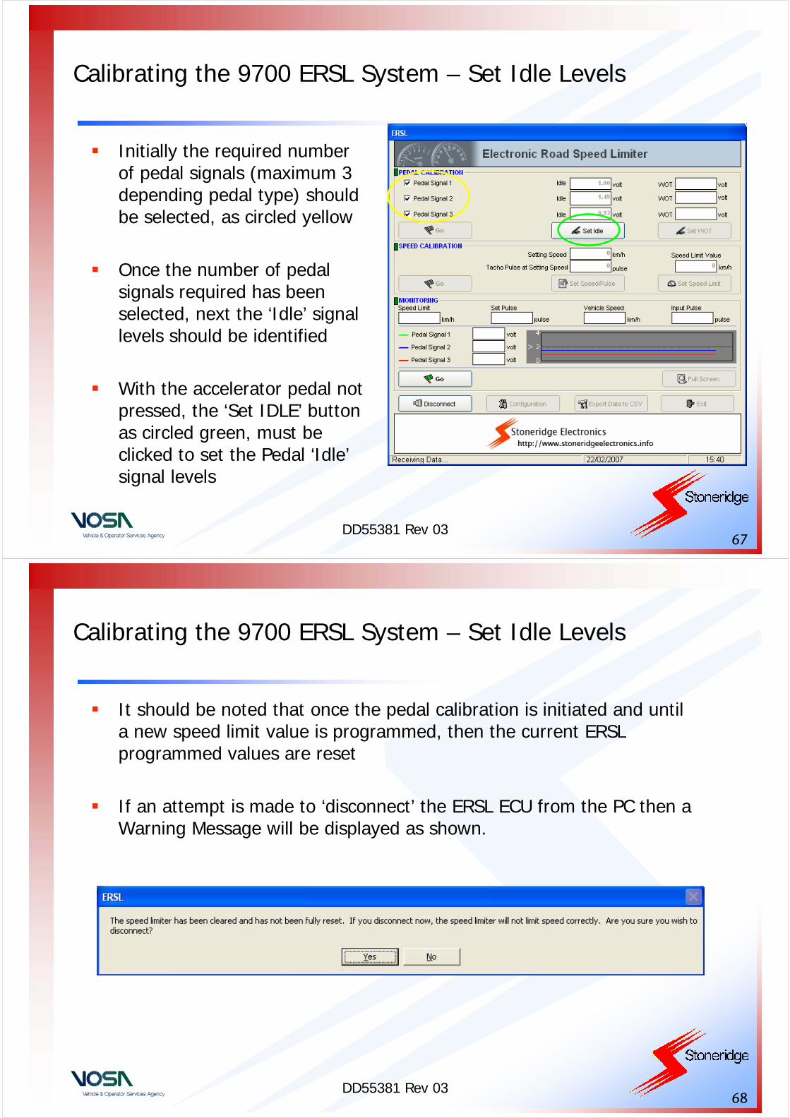
Initially the required number of pedal signals (maximum 3 depending pedal type) should be selected, as circled yellow
Once the number of pedal signals required has been selected, next the ‘Idle’ signal levels should be identified
With the accelerator pedal not pressed, the ‘Set IDLE’ button as circled green, must be clicked to set the Pedal ‘Idle’signal levels
DD55381 Rev 0368
Calibrating the 9700 ERSL System – Set Idle Levels
It should be noted that once the pedal calibration is initiated and until a new speed limit value is programmed, then the current ERSL programmed values are reset
If an attempt is made to ‘disconnect’ the ERSL ECU from the PC then a Warning Message will be displayed as shown.
DD55381 Rev 0369
Calibrating the 9700 ERSL System – Set WOT levels
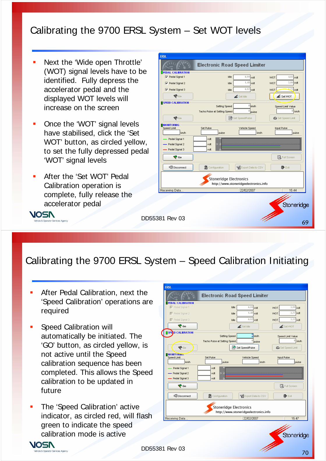
Next the ‘Wide open Throttle’(WOT) signal levels have to be identified. Fully depress the accelerator pedal and the displayed WOT levels will increase on the screen
Once the ‘WOT’ signal levels have stabilised, click the ‘Set WOT’ button, as circled yellow, to set the fully depressed pedal ‘WOT’ signal levels
After the ‘Set WOT’ Pedal Calibration operation is complete, fully release the accelerator pedal
DD55381 Rev 0370
Calibrating the 9700 ERSL System – Speed Calibration Initiating
After Pedal Calibration, next the ‘Speed Calibration’ operations are required
Speed Calibration will automatically be initiated. The ‘GO’ button, as circled yellow, is not active until the Speed calibration sequence has been completed. This allows the Speed calibration to be updated in future
The ‘Speed Calibration’ active indicator, as circled red, will flash green to indicate the speed calibration mode is active

DD55381 Rev 0371
Calibrating the 9700 ERSL System – Setting Speed
With the ‘Speed Calibration’active indicator flashing green, the next stage is to program the 9700 Control parameter ‘Setting Speed’
The setting speed value should first be input in the box circled yellow
This value is typically 60km/h and allows the ERSL software to determine the rate of speed pulses from the Tachograph, for the required control speed
DD55381 Rev 0372
Calibrating the 9700 ERSL System – Setting Speed
With the ‘Set Speed’ value at 60 km/h, a MKII Tachograph Programmer or equivalent, should be connected to the Tachograph in order to ‘Speed Simulate’ the ERSL system at the required Setting Speed value of 60km/h
When executing the MKII Speed Simulation function –see description in next section – the MKII Speed Simulator speed, the Tachograph speed and the ‘setting speed’ value must all be the same, 60 km/h in this case
DD55381 Rev 0373
Calibrating the 9700 ERSL System – Setting Speed
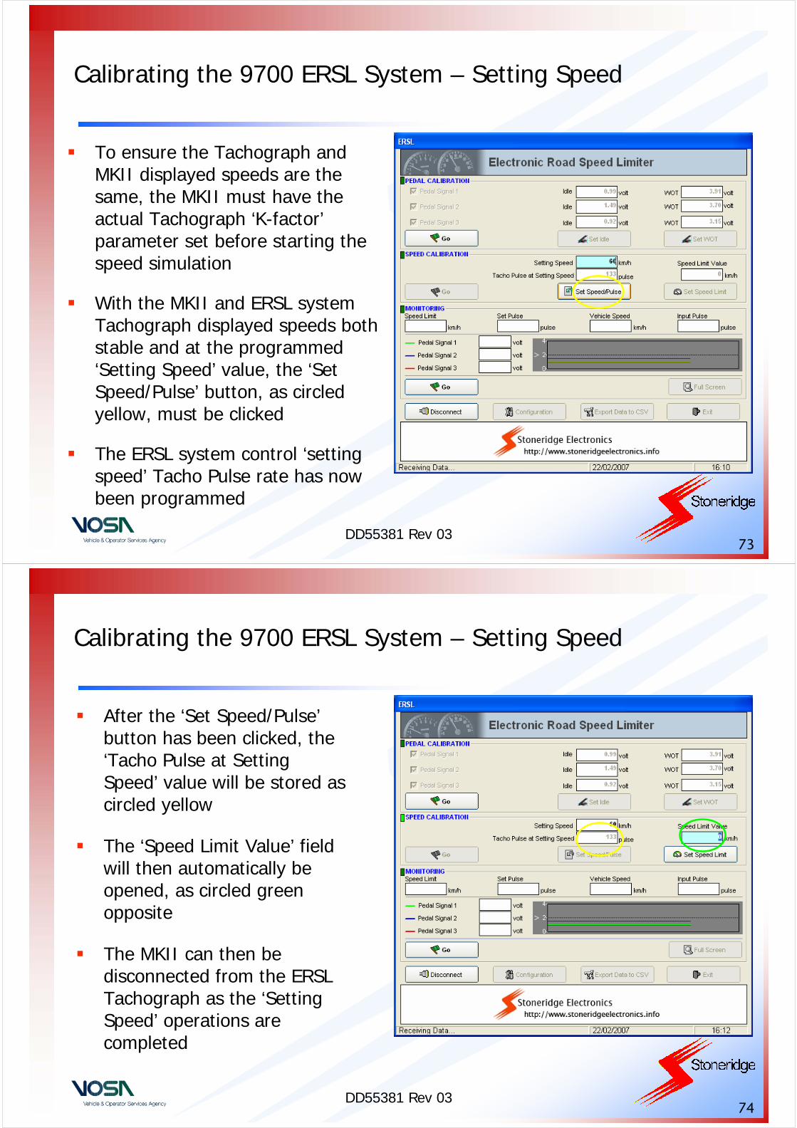
To ensure the Tachograph and MKII displayed speeds are the same, the MKII must have the actual Tachograph ‘K-factor’parameter set before starting the speed simulation
With the MKII and ERSL system Tachograph displayed speeds both stable and at the programmed ‘Setting Speed’ value, the ‘Set Speed/Pulse’ button, as circled yellow, must be clicked
The ERSL system control ‘setting speed’ Tacho Pulse rate has now been programmed
DD55381 Rev 0374
Calibrating the 9700 ERSL System – Setting Speed
After the ‘Set Speed/Pulse’button has been clicked, the ‘Tacho Pulse at Setting Speed’ value will be stored as circled yellow
The ‘Speed Limit Value’ field will then automatically be opened, as circled green opposite
The MKII can then be disconnected from the ERSL Tachograph as the ‘Setting Speed’ operations are completed
DD55381 Rev 0375
Calibrating the 9700 ERSL System – Setting ERSL Speed Limit
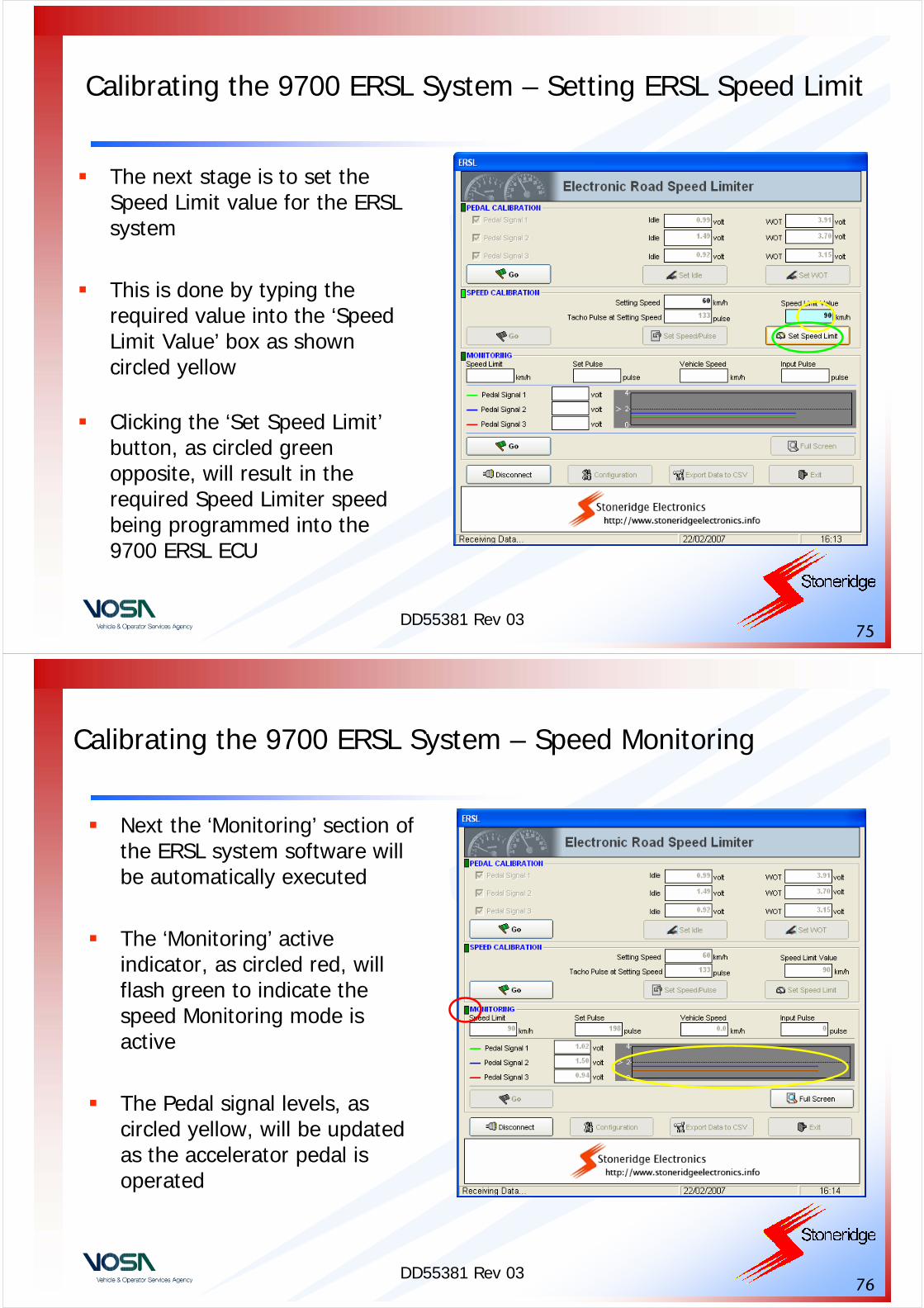
The next stage is to set the Speed Limit value for the ERSL system
This is done by typing the required value into the ‘Speed Limit Value’ box as shown circled yellow
Clicking the ‘Set Speed Limit’button, as circled green opposite, will result in the required Speed Limiter speed being programmed into the 9700 ERSL ECU
DD55381 Rev 0376
Calibrating the 9700 ERSL System – Speed Monitoring
Next the ‘Monitoring’ section of the ERSL system software will be automatically executed
The ‘Monitoring’ active indicator, as circled red, will flash green to indicate the speed Monitoring mode is active
The Pedal signal levels, as circled yellow, will be updated as the accelerator pedal is operated
DD55381 Rev 0377
Calibrating the 9700 ERSL System – Speed Monitoring
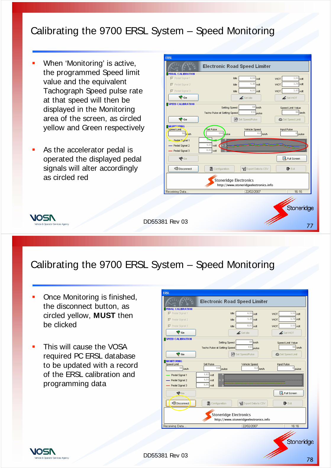
When ‘Monitoring’ is active, the programmed Speed limit value and the equivalent Tachograph Speed pulse rate at that speed will then be displayed in the Monitoring area of the screen, as circled yellow and Green respectively
As the accelerator pedal is operated the displayed pedal signals will alter accordingly as circled red
DD55381 Rev 0378
Calibrating the 9700 ERSL System – Speed Monitoring
Once Monitoring is finished, the disconnect button, as circled yellow, MUST then be clicked
This will cause the VOSA required PC ERSL database to be updated with a record of the ERSL calibration and programming data
DD55381 Rev 0379
Calibrating the 9700 ERSL System – Exiting
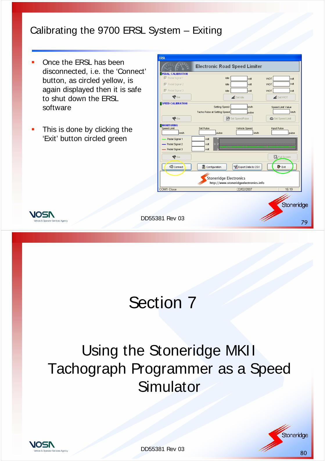
Once the ERSL has been disconnected, i.e. the ‘Connect’button, as circled yellow, is again displayed then it is safe to shut down the ERSL software
This is done by clicking the ‘Exit’ button circled green
DD55381 Rev 0380
Section 7
Using the Stoneridge MKII Tachograph Programmer as a Speed
Simulator
DD55381 Rev 0381
Stoneridge MKII Programmer – Introduction
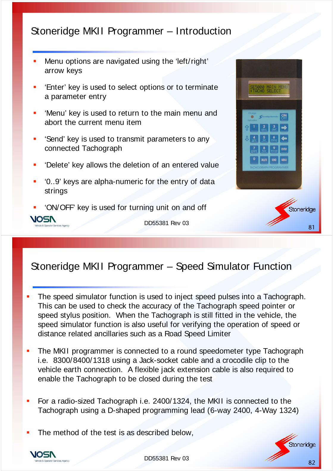
Menu options are navigated using the ‘left/right’arrow keys
‘Enter’ key is used to select options or to terminate a parameter entry
‘Menu’ key is used to return to the main menu and abort the current menu item
‘Send’ key is used to transmit parameters to any connected Tachograph
‘Delete’ key allows the deletion of an entered value
‘0..9’ keys are alpha-numeric for the entry of data strings
‘ON/OFF’ key is used for turning unit on and off
DD55381 Rev 0382
Stoneridge MKII Programmer – Speed Simulator Function
The speed simulator function is used to inject speed pulses into a Tachograph. This can be used to check the accuracy of the Tachograph speed pointer or speed stylus position. When the Tachograph is still fitted in the vehicle, the speed simulator function is also useful for verifying the operation of speed or distance related ancillaries such as a Road Speed Limiter
The MKII programmer is connected to a round speedometer type Tachograph i.e. 8300/8400/1318 using a Jack-socket cable and a crocodile clip to the vehicle earth connection. A flexible jack extension cable is also required to enable the Tachograph to be closed during the test
For a radio-sized Tachograph i.e. 2400/1324, the MKII is connected to the Tachograph using a D-shaped programming lead (6-way 2400, 4-Way 1324)
The method of the test is as described below,

DD55381 Rev 0383
Stoneridge MKII Programmer – Speed Simulator Function
K=8000 Pul/kmSpeed=50 km/h
The Programmer will now inject speed pulses into the Tachograph.
Enter speed: km/h
Key in the speed required and press ENTER. Note that there is a minimum detectable speed for each Tachograph type, which depends on the K-factor but may be up to 20km/h. Below this, the speed will reset to 0km/h.
Select K-factor:8000 Pul/km?
Press the DELETE key, and enter the value of K-factor that the Tachograph is currently set to into the Programmer. Then press ENTER.
VR8400 MAIN MENU:SPEED SIMULATOR
Select SPEED SIMULATOR from the MAIN MENU and press ENTER
DD55381 Rev 0384
Stoneridge MKII Programmer – Speed Simulator Function
VR8400 MAIN MENU:SPEED SIMULATOR
Press ENTER to key in a new speed or MENU to return to the MAIN MENU.
Distance=1090 mPress <ENTER>
When the test is completed press ENTER. The unit will now display the total distance covered (in metres).
K = 8000 Pul/kmSpeed=51 km/h
Use the ↑ and ↓ (1 and 4) keys to increase or decrease speed.

DD55381 Rev 0385
Section 8
Testing a Programmed 9700 Electronic Road Speed Limiter
DD55381 Rev 0386
Testing the 9700 ERSL System
Once the 9700 ERSL ECU has been fully calibrated and programmed as described previously, the 9700 can then be fitted to the vehicle and tested either on the road, with a rolling road or by using the MKII Programmer speed simulator function described above
Alternatively the programmed values can be checked with the ERSLsoftware running and the vehicle fitted with the ERSL running on a rolling road
As shown below (circled yellow and green), the ‘Vh speed’ and ‘Input Pulse’ rates along with the Pedal Signals can be seen to change when driving on the rolling road. The Vh Speed and Input Pulse rates are similar to that of the set speed and set pulses at wide open throttle, which shows that the limiter is responding
Also the Pedal Signals should be in the same ratio from the original IDLE and WOT results seen in the pedal calibration field
DD55381 Rev 0387
Testing the 9700 ERSL System – PC Software – Monitoring
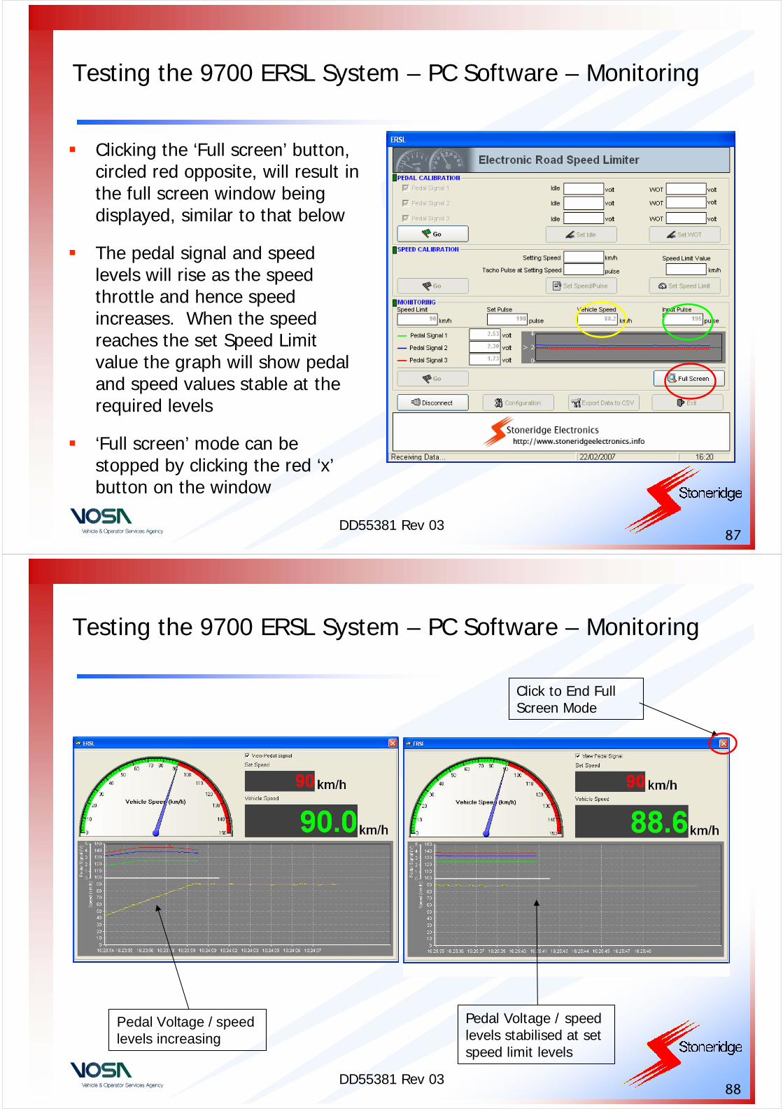
Clicking the ‘Full screen’ button, circled red opposite, will result in the full screen window being displayed, similar to that below
The pedal signal and speed levels will rise as the speed throttle and hence speed increases. When the speed reaches the set Speed Limit value the graph will show pedal and speed values stable at the required levels
‘Full screen’ mode can be stopped by clicking the red ‘x’button on the window
DD55381 Rev 0388
Testing the 9700 ERSL System – PC Software – Monitoring
Pedal Voltage / speed levels increasing
Click to End Full Screen Mode
Pedal Voltage / speed levels stabilised at set speed limit levels
DD55381 Rev 0389
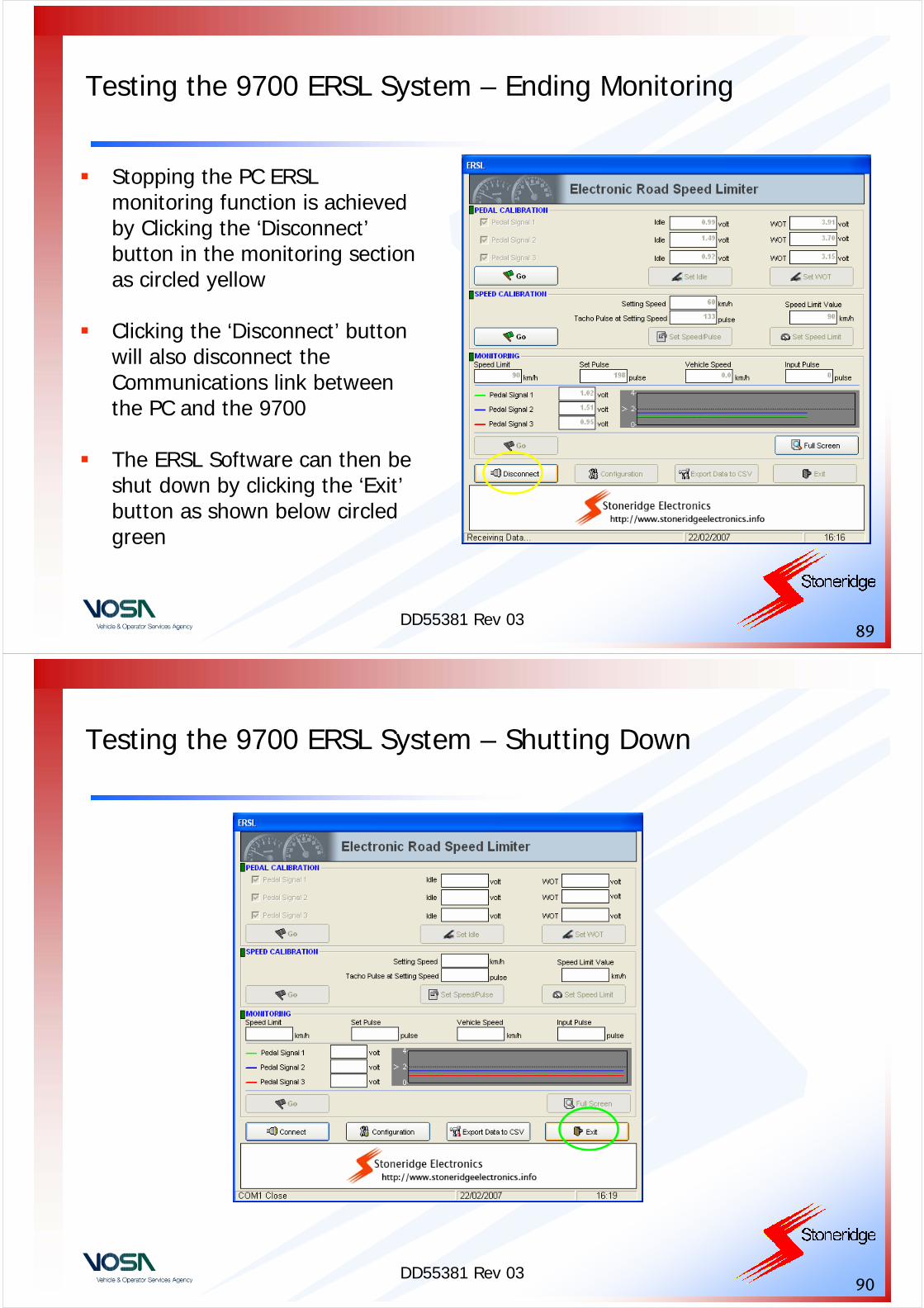
Testing the 9700 ERSL System – Ending Monitoring
Stopping the PC ERSL monitoring function is achieved by Clicking the ‘Disconnect’button in the monitoring section as circled yellow
Clicking the ‘Disconnect’ button will also disconnect the Communications link between the PC and the 9700
The ERSL Software can then be shut down by clicking the ‘Exit’button as shown below circled green
DD55381 Rev 0390
Testing the 9700 ERSL System – Shutting Down

DD55381 Rev 0391
Section 9
Practical Exercise Using a 9700 Electronic Road Speed Limiter
DD55381 Rev 0392
Practical Exercise Using the 9700 ERSL System
Objective• The objective is to calibrate, program and test a Stoneridge 9700
ERSL system
Equipment Required• Stoneridge 9700 ERSL ECU, Stoneridge ERSL Training Case, PC
running the Stoneridge 9700 ERSL Software, ERSL Software Key
Exercise• Calibrate, Program and test with a MKII programmer the supplied
Stoneridge 9700 ERSL ECU so that it can be fitted into a bus weighing 6500 kg that was first registered on 01/06/2005. The Vehicle VIN is ‘RSL9700STONERIDGE’ and the Vehicle VRN is ‘ST05ABC’