stillen 350z stage 2 supercharger installation instructions
DESCRIPTION
Stillen 350Z Stage 2 Supercharger Installation InstructionsTRANSCRIPT
Steve Millen Sportparts, Inc. - 3176 Airway Avenue - Costa Mesa, CA 92626 - Phone. 714-540-5566 - Fax. 714-540-5784 - www.stillen.com
Rev. P
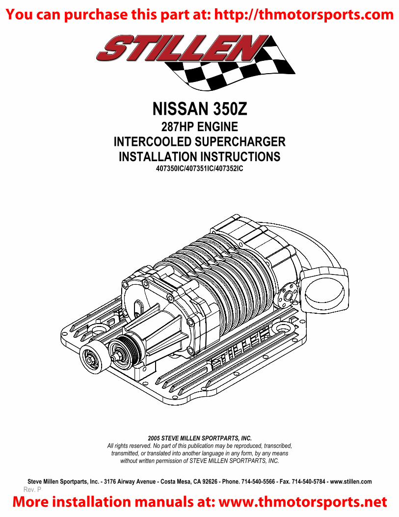
NISSAN 350Z 287HP ENGINE
INTERCOOLED SUPERCHARGER INSTALLATION INSTRUCTIONS
407350IC/407351IC/407352IC
2005 STEVE MILLEN SPORTPARTS, INC.
All rights reserved. No part of this publication may be reproduced, transcribed, transmitted, or translated into another language in any form, by any means
without written permission of STEVE MILLEN SPORTPARTS, INC.
You can purchase this part at: http://thmotorsports.com
More installation manuals at: www.thmotorsports.net

Steve Millen Sportparts, Inc. - 3176 Airway Avenue - Costa Mesa, CA 92626 - Phone. 714-540-5566 - Fax. 714-540-5784 - www.stillen.com
Page 2 of 20
Congratulations… on your purchasing the STILLEN supercharger system for your 350Z.
For the smoothest installation and best performance and reliability from your supercharger, please follow these simple points.
• Changing the spark plugs to 1 range colder is required with this kit. NGK part# PLFR6A-11 gapped to 1.1mm (0.043in.)
• Read all the instructions to familiarize yourself with various parts and operations.
• Layout all parts on a bench and check that all of the parts are accounted for per the Parts List. Some parts on the list are already assembled, torqued and sealed, DO NOT DISASSEMBLE. If any parts are missing or damaged, please call us immediately.
• Gather all required tools before starting installation.
• Use 91 octane or higher fuel. Fuel quality will vary depending on manufacturer, always use quality fuel.
• This kit is designed for stock engines. If the engine is modified in any way, contact STILLEN to discuss any conflicts or issues that could affect the superchargers performance.
• Aftermarket re-calibration devices that modify the fuel or spark curve are not recommended and may cause engine damage or failure.
• The addition of headers or removal of the catalytic converters will affect the performance of this kit.
• This STILLEN supercharger system is intended to be installed on a well maintained, healthy engine. We do not recommend installing this system on a sick or damaged engine, this can result in premature engine failure and possible supercharger failure. Stillen is not responsible for damages due to improper installation or damages due to installation on worn or damaged engines.
• Do not alter, modify, or adjust the STILLEN supercharger system in any way, shape or form. Unauthorized changes to boost levels, electronics or any other system will void warranties and can cause catastrophic damage. If this system is being installed on a new vehicle it is very important that factory break-in procedures are followed to prevent any adverse affect on the vehicle.
!!!!����!!!! WARNING:
WE STRONGLY URGE THAT YOU REFER THIS INSTALLATION TO AN ASE CERTIFIED MECHANIC
WITH EXPERIENCE IN THIS TYPE OF INSTALLATION. FAILURE TO DO SO COULD LIMIT YOUR TECH SUPPORT AND AFFECT YOUR WARRANTY.
You can purchase this part at: http://thmotorsports.com
More installation manuals at: www.thmotorsports.net

Steve Millen Sportparts, Inc. - 3176 Airway Avenue - Costa Mesa, CA 92626 - Phone. 714-540-5566 - Fax. 714-540-5784 - www.stillen.com
Page 3 of 20
Installation:
1. Layout all parts on bench and check that all of the parts are accounted for per packing list. Read all instructions before starting to familiarize yourself with various parts and operations. Change the spark plugs to 1 range colder. NGK part #PLFR6A-11 gapped to 1.1mm (0.043 in.)
2. At this time it is best to remove the hood and place it in a safe place. Open radiator petcock and drain coolant. Also disconnect negative terminal of battery before proceeding further.
3. Next remove the decorative engine cover and the strut tower brace. Neither one of these items will be reused after supercharger installation.
4. Remove the air tube that connects the throttle body to the mass air flow sensor. Don’t forget to disconnect the crankcase vent tube that is attached to it also. Save this tube, as it will be reused later. (PHOTO 1)
5. Remove the four bolts and electrical connector from the throttle body. Set aside the gasket and throttle body for later use.
6. Remove the top half of the upper plenum. This is accomplished by removing the 16 bolts and 2 nuts that connect the two halves. Remove all brackets attached to upper half. Remove 2 vacuum lines, 2 coolant lines and lift off top plenum.(PHOTO 2)
7. Remove bottom half by removing the six bolts down the center and the two 6mm nuts at each end. Remove PCV hose and lift off bottom half. Save old gasket for reuse. It is a good idea to cover the open lower plenum with tape to prevent foreign matter from entering. (PHOTO 3)
8. Installing the double pulley on the front of the engine. Remove belt and stock pulley and set aside. Use the supplied M6x16MM bolts and lock washers and install pulley. Torque bolts to 45-50 in-lbs. (PHOTO 4)
You can purchase this part at: http://thmotorsports.com
More installation manuals at: www.thmotorsports.net
Steve Millen Sportparts, Inc. - 3176 Airway Avenue - Costa Mesa, CA 92626 - Phone. 714-540-5566 - Fax. 714-540-5784 - www.stillen.com
Page 4 of 20
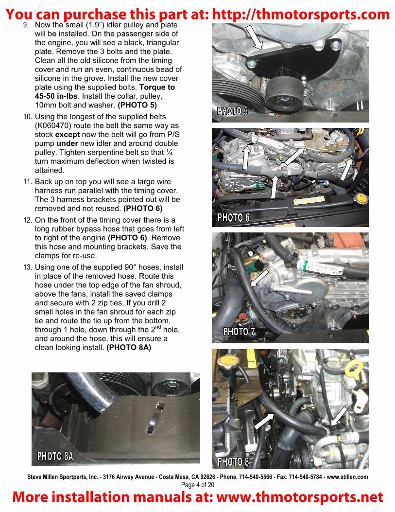
9. Now the small (1.9”) idler pulley and plate will be installed. On the passenger side of the engine, you will see a black, triangular plate. Remove the 3 bolts and the plate. Clean all the old silicone from the timing cover and run an even, continuous bead of silicone in the grove. Install the new cover plate using the supplied bolts. Torque to 45-50 in-lbs. Install the collar, pulley, 10mm bolt and washer. (PHOTO 5)
10. Using the longest of the supplied belts (K060470) route the belt the same way as stock except now the belt will go from P/S pump under new idler and around double pulley. Tighten serpentine belt so that ¼ turn maximum deflection when twisted is attained.
11. Back up on top you will see a large wire harness run parallel with the timing cover. The 3 harness brackets pointed out will be removed and not reused. (PHOTO 6)
12. On the front of the timing cover there is a long rubber bypass hose that goes from left to right of the engine (PHOTO 6). Remove this hose and mounting brackets. Save the clamps for re-use.
13. Using one of the supplied 90° hoses, install in place of the removed hose. Route this hose under the top edge of the fan shroud, above the fans, install the saved clamps and secure with 2 zip ties. If you drill 2 small holes in the fan shroud for each zip tie and route the tie up from the bottom, through 1 hole, down through the 2nd hole, and around the hose, this will ensure a clean looking install. (PHOTO 8A)
You can purchase this part at: http://thmotorsports.com
More installation manuals at: www.thmotorsports.net
Steve Millen Sportparts, Inc. - 3176 Airway Avenue - Costa Mesa, CA 92626 - Phone. 714-540-5566 - Fax. 714-540-5784 - www.stillen.com
Page 5 of 20
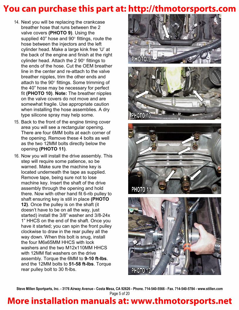
14. Next you will be replacing the crankcase breather hose that runs between the 2 valve covers (PHOTO 9). Using the
supplied 40” hose and 90° fittings, route the hose between the injectors and the left cylinder head. Make a large kink free ‘U’ at the back of the engine and finish at the right
cylinder head. Attach the 2 90° fittings to the ends of the hose. Cut the OEM breather line in the center and re-attach to the valve breather nipples, trim the other ends and
attach to the 90° fittings. Some trimming of the 40” hose may be necessary for perfect fit (PHOTO 10). Note: The breather nipples on the valve covers do not move and are somewhat fragile. Use appropriate caution when installing the hose assemblies. A dry type silicone spray may help some.
15. Back to the front of the engine timing cover area you will see a rectangular opening. There are four 6MM bolts at each corner of the opening. Remove these 4 bolts as well as the two 12MM bolts directly below the opening (PHOTO 11).
16. Now you will install the drive assembly. This step will require some patience, so be warned. Make sure the machine key is located underneath the tape as supplied. Remove tape, being sure not to lose machine key. Insert the shaft of the drive assembly through the opening and hold there. Now with other hand fit 6-rib pulley to shaft ensuring key is still in place (PHOTO 12). Once the pulley is on the shaft (it doesn’t have to be on all the way, just started) install the 3/8” washer and 3/8-24x 1” HHCS on the end of the shaft. Once you have it started; you can spin the front pulley clockwise to draw in the rear pulley all the way down. When this bolt is snug, install the four M6x65MM HHCS with lock washers and the two M12x110MM HHCS with 12MM flat washers on the drive assembly. Torque the 6MM to 9-10 ft-lbs. and the 12MM bolts to 51-58 ft-lbs. Torque rear pulley bolt to 30 ft-lbs.
You can purchase this part at: http://thmotorsports.com
More installation manuals at: www.thmotorsports.net

Steve Millen Sportparts, Inc. - 3176 Airway Avenue - Costa Mesa, CA 92626 - Phone. 714-540-5566 - Fax. 714-540-5784 - www.stillen.com
Page 6 of 20
17. Install the lower tensioner assembly onto the just installed drive unit. Use the three supplied M12x50MM flat SHCS and torque to 40 ft-lbs. (PHOTO 13).
18. Install the K060288 belt around the double pulley, idler and drive assembly. If you have to remove the idler pulley for belt installation, be sure to install the spacer and dust shields in proper order. Tighten this belt so ¼ turn maximum turn when twisted is attained.
Note: Fuel under high pressure. Use appropriate safety precautions when working with the fuel rail assembly.
19. On the passenger side fuel rail there is a hard fuel feed line. Disconnect the feed line at the flange and insert the fuel rail spacer (without the fitting) and O-ring between the hard line and stock fuel rail. The O-ring will seat against the flange on the fuel rail. Using the supplied M6x45MM bolts, tighten to 50-60 in-lbs. Install the adapter (with the fitting) and O-ring underneath the damper on the feed line with the fitting facing the rear of the vehicle and torque to the same. (PHOTO 14&15).
You can purchase this part at: http://thmotorsports.com
More installation manuals at: www.thmotorsports.net

Steve Millen Sportparts, Inc. - 3176 Airway Avenue - Costa Mesa, CA 92626 - Phone. 714-540-5566 - Fax. 714-540-5784 - www.stillen.com
Page 7 of 20
20. Back on top of the engine you will see two 6MM studs sticking out of the lower plenum. These will have to be removed. After removing tape covering plenum, lay Stillen lower plenum on top making sure to keep factory metal gasket in place. Using the seven M6x35MM Flat SHCS in the recessed holes torque these to 9-10ft-lbs. (PHOTO 16)
21. On the passenger side of the lower plenum you will see a 1/8” brass nipple tapped into it. Attach the supplied 1/8” vacuum line to the fitting. This line will be routed to the fuel/timing control box later.
22. Now install the intercooler/supercharger assembly. A friend’s help is useful during this step. Using the supplied tube of anaerobic sealer (DO NOT USE SILICONE), run a continuous 1/8” bead around the entire mating surface of the lower plenum. Set the short, 6-rib belt in place around the lower pulley and hold in place while your helper angles the nose of the supercharger through the upper portion of the belt. Gently lower the assembly onto the lower plenum, trying not to disturb the bead of sealer. (PHOTO 17) Insert the supplied ¼-20x5/8” SHCS in all the holes except for the 3 spots noted with the arrows (PHOTO 16). The front arrow will use the M6x80MM SHCS and the rear corner arrow in the corner will take the ¼-20x1 3/8” SHCS. The center rear arrow uses a ¼”-20 x 1” HHCS (PHOTO 17A). At rear corner, remove the EVAP control solenoid from its bracket and install in onto the new, supplied bracket. Mount the EVAP solenoid, fuel regulator brace box under the rear corner bolt. (PHOTO 18) Torque all bolts to 85-inch lbs.
23. Install the fuel line, using the 2 supplies 90° fittings, between the fuel adapter and the fuel injector block. This is located on the lower portion of the aluminum inlet at the back of the supercharger. Tighten all fittings sufficiently to ensure no leaks. DO NOT OVER TIGHTEN! (PHOTO 18)
You can purchase this part at: http://thmotorsports.com
More installation manuals at: www.thmotorsports.net

Steve Millen Sportparts, Inc. - 3176 Airway Avenue - Costa Mesa, CA 92626 - Phone. 714-540-5566 - Fax. 714-540-5784 - www.stillen.com
Page 8 of 20
24. Install the upper tensioner. Apply a drop of thread locking compound to the 3 1/4-20x3/4 bolts. Using these 3 bolts and lock washers, mount the tensioner to the top plate (PHOTO 19). Be sure to index the center bolt so the tensioner slides past it without hitting. Tighten the long tensioner bolt until the non-tensioned side of the belt stops at about 90˚ when twisted. Tighten the lock nut on the front of the new pulley. Tighten the long adjuster bolt until the lock washer is compressed to keep the bolt from vibrating loose.
25. Below the throttle body flange on the supercharger inlet you will see two 5/16” water barbs. Attach the inner line; replace the outer line with supplied 5/16” hose and clamps (PHOTO 21A).
26. Bolt the factory throttle body to the flange on the inlet. Use the original steel gasket and 6MM SHCS. Tighten these to 64-85 in-lbs. Connect the TPS connector also to the throttle body.
27. Next route the vacuum lines. You will be moving the brake booster vacuum line from the engine compartment to the master cylinder compartment and trimming it to fit in place of the vacuum line on the booster. This vacuum line contains a one-way check valve, make sure the arrow on the vacuum line points to the engine. (PHOTO 20&21) Route the rest of the vacuum lines per the supplied diagram. (FIGURE 2) Make sure all the lines are free from kinks and are securely attached.
28. Now install the throttle body tube removed in (PHOTO 1). Don’t forget to attach the crankcase vent hose to the throttle body tube. Tighten all hose clamps.
You can purchase this part at: http://thmotorsports.com
More installation manuals at: www.thmotorsports.net

Steve Millen Sportparts, Inc. - 3176 Airway Avenue - Costa Mesa, CA 92626 - Phone. 714-540-5566 - Fax. 714-540-5784 - www.stillen.com
Page 9 of 20
Fuel/timing control unit:
Next the fuel / timing computer will be wired in. The easiest way to do this is by pulling the ECU connector out of the body and into the engine compartment where it can be worked on in the open.
Due to the sensitivity of the signals, all connections MUST be soldered and covered with heat shrink or electrical tape.
Depending on the application, you may have unused wires on the Stillen control unit. Coil these up and zip tie out of the way. DO NOT CUT THEM OFF.
1. On the passengers side floor, remove the right kick panel, as well as the under dash cover.
2. Unplug the ECU connector by pressing the locking clip and lifting the lever, the connector will uncouple itself from the ECU. Unplug the remaining connectors on the loom. The number and type of connectors will vary from vehicle to vehicle. (PHOTO 22)
3. In the engine compartment, remove the passenger side cowl cover to reveal the bulkhead seal for the harness. Grab the edge of the seal and pull up until it pops out of the hole. Gently pull the harness and connectors out through the hole and lay them on the fender. (PHOTO 23&24)
You can purchase this part at: http://thmotorsports.com
More installation manuals at: www.thmotorsports.net

Steve Millen Sportparts, Inc. - 3176 Airway Avenue - Costa Mesa, CA 92626 - Phone. 714-540-5566 - Fax. 714-540-5784 - www.stillen.com
Page 10 of 20
4. Remove the electrical tape from the harness near the ECU connector and peel back the sleeve to expose the wires.
5. Using a screwdriver, carefully pry off the plastic cover on the back of the ECU connector to access the wires as they enter the connector. (PHOTO 25)
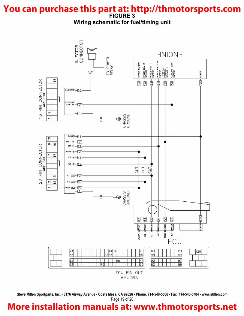
Note: When referring to a pin-out diagram, it is always viewed from the wire side of the connector. Due to different models or vehicle options, wire colors may vary. Always refer to the pin number (wire location on the connector), rather than the color.
Note: During the installation of the control unit, you will be making 2 types of connections, “Intercept” and “T”.
“T” connections just monitor a signal going through a wire. This connection only requires tapping into the wire. This connection is made on 4 ECU wires, pin #s 34, 50, 73 and 120
“Intercept” connections modify a signal in a wire. This requires cutting the wire from the sensor and routing it into the control unit, then routing the modified signal to the ECU. This connection is made on 3 ECU wires, pin #s 13, 14 and 33.
6. Refer to the wire diagram for wiring in the control unit. (FIGURE 3)
7. Reinstall the plastic cover onto the back of the ECU connector. Pull the sleeve back down over the wires and tape closed using electrical tape.
You can purchase this part at: http://thmotorsports.com
More installation manuals at: www.thmotorsports.net

Steve Millen Sportparts, Inc. - 3176 Airway Avenue - Costa Mesa, CA 92626 - Phone. 714-540-5566 - Fax. 714-540-5784 - www.stillen.com
Page 11 of 20
8. Using a razor blade, carefully create a slice in the boot on the bulkhead seal and route the 1/8” vacuum line and the negative injector wire through. Attach the negative (Brown) injector wire to wire 16 of the 16 pin connector on the Stillen control unit connector. (PHOTO 26)
9. Gently push all the connectors back down the hole and into the body. Press the bulkhead into the hole until it clicks into place.
10. Connect all connectors. Plug in the Stillen control unit and connect the vacuum line using the 1/8” fitting. Attach the control unit to the wall or module using the Velcro and reinstall the panels. (PHOTO 27)
You can purchase this part at: http://thmotorsports.com
More installation manuals at: www.thmotorsports.net

Steve Millen Sportparts, Inc. - 3176 Airway Avenue - Costa Mesa, CA 92626 - Phone. 714-540-5566 - Fax. 714-540-5784 - www.stillen.com
Page 12 of 20
Intercooler installation:
Begin your installation by lifting the vehicle and securely placing it on jack stands. Observe all proper safety precautions when working on the vehicle.
1. Remove the front fascia. It is attached via push-clips and 6MM bolts on top and bottom of the fascia. There are 2 bolts on each side that are behind the inner splashguard, the guard will have to be moved to allow access.
2. Mount the heat exchanger to the front bumper mounts using supplied brackets. The heat exchanger should be mounted as high up on the brackets as possible. (PHOTO 28)
3. Remove the coolant overflow reservoir support bracket from the passenger side of the vehicle. Slide the OEM bracket off the bottle and attach the supplied mounting bracket to the reservoir. Mount the reservoir in the spot forward of the left wheel well as shown in PHOTO 29. The bracket will mount underneath the fascia support bracket and will be attached using the OEM bolts. The supplied ¼”overflow hose will be routed through the opening directly above it and to the radiator. The reservoir can be filled through the opening via a long funnel to maintain proper coolant level.
4. Remove and discard the passenger side air deflector /splashguard held in place by 3 plastic clips Mount the intercooler pump using the supplied Adel clamp as shown in PHOTO 30. The aluminum spacer goes between the tabs of the Adel clamp to prevent the pump from being damaged by the clamp. You will be using the mounting hole shown by the arrow in PHOTO 28. Route the positive wire for the pump into the engine compartment by the battery and leave there for now. Connect the negative wire to a suitable chassis ground.
You can purchase this part at: http://thmotorsports.com
More installation manuals at: www.thmotorsports.net

Steve Millen Sportparts, Inc. - 3176 Airway Avenue - Costa Mesa, CA 92626 - Phone. 714-540-5566 - Fax. 714-540-5784 - www.stillen.com
Page 13 of 20
5. Cut a piece of ¾ “heater hose approximately 30” and route it to the inlet of the water pump (bottom fitting). Route this hose into the engine compartment as shown in PHOTO 31.
6. Using the supplied 12” section of dual ID ¾” X 5/8” heater hose, trim to fit from the heat exchanger fitting to the outlet of the pump. Secure the hose with the supplied clamps. Route the supplied 60” piece of molded hose onto the rear intercooler fitting to the lower fitting of the heat exchanger but do not connect at this time. Make sure the 90-degree end is the one in the engine compartment. Use a supplied Adel clamp and mount it next to the oil dipstick as shown in PHOTO 32.
7. Install the header tank in the space created by removal of the coolant reservoir. The hose that was pictured in PHOTO 31 will be attached to the fitting on the bottom of the header tank, trim hose length for proper fit. Secure the tank using the 3 bolts removed from the coolant bottle removal. Connect the other end of hose to the inlet of pump and secure with hose clamp.
8. Connect the 90-degree end of the molded hose you routed in step # 6 to the front intercooler fitting. Trim excess length off 90-degree end to allow for hood clearance. Ensure routing is free from kinks and sharp objects. If routing is satisfactory cut to fit the other end of hose to the lower right fitting of the heat exchanger and secure with hose clamps. PHOTO 33. You will also need to use another supplied Adel clamp to secure the hose next to the coolant bottle.
9. Install the 90-degree end of the other 60” molded hose onto the front intercooler fitting. Trim excess length off 90-degree end to allow for hood clearance. Route the hose to the header tank (PHOTO 34).
Tighten Adel clamps and install hose clamps at both ends.
10. Now you will install the supplied relay and harness. In the battery compartment you will see the battery ground cable secured
You can purchase this part at: http://thmotorsports.com
More installation manuals at: www.thmotorsports.net
Steve Millen Sportparts, Inc. - 3176 Airway Avenue - Costa Mesa, CA 92626 - Phone. 714-540-5566 - Fax. 714-540-5784 - www.stillen.com
Page 14 of 20
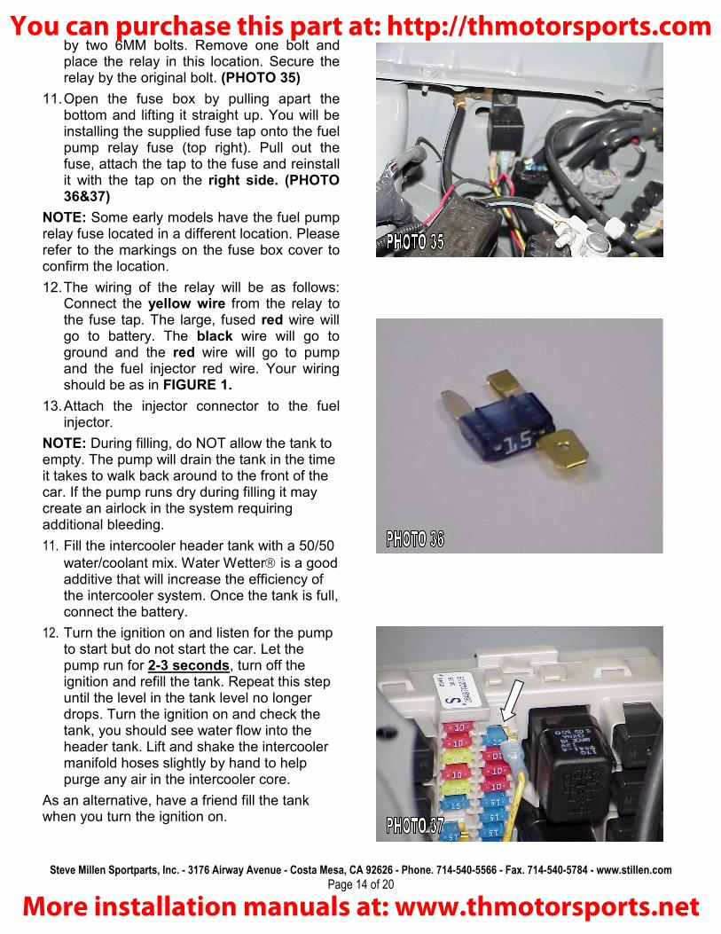
by two 6MM bolts. Remove one bolt and place the relay in this location. Secure the relay by the original bolt. (PHOTO 35)
11. Open the fuse box by pulling apart the bottom and lifting it straight up. You will be installing the supplied fuse tap onto the fuel pump relay fuse (top right). Pull out the fuse, attach the tap to the fuse and reinstall it with the tap on the right side. (PHOTO 36&37)
NOTE: Some early models have the fuel pump relay fuse located in a different location. Please refer to the markings on the fuse box cover to confirm the location.
12. The wiring of the relay will be as follows: Connect the yellow wire from the relay to the fuse tap. The large, fused red wire will go to battery. The black wire will go to ground and the red wire will go to pump and the fuel injector red wire. Your wiring should be as in FIGURE 1.
13. Attach the injector connector to the fuel injector.
NOTE: During filling, do NOT allow the tank to empty. The pump will drain the tank in the time it takes to walk back around to the front of the car. If the pump runs dry during filling it may create an airlock in the system requiring additional bleeding.
11. Fill the intercooler header tank with a 50/50
water/coolant mix. Water Wetter is a good additive that will increase the efficiency of the intercooler system. Once the tank is full, connect the battery.
12. Turn the ignition on and listen for the pump to start but do not start the car. Let the pump run for 2-3 seconds, turn off the ignition and refill the tank. Repeat this step until the level in the tank level no longer drops. Turn the ignition on and check the tank, you should see water flow into the header tank. Lift and shake the intercooler manifold hoses slightly by hand to help purge any air in the intercooler core.
As an alternative, have a friend fill the tank when you turn the ignition on.
You can purchase this part at: http://thmotorsports.com
More installation manuals at: www.thmotorsports.net

Steve Millen Sportparts, Inc. - 3176 Airway Avenue - Costa Mesa, CA 92626 - Phone. 714-540-5566 - Fax. 714-540-5784 - www.stillen.com
Page 15 of 20
13. Once no leaks are verified on the intercooler system, start the engine. Check the engine for coolant, fuel and vacuum leaks. If everything is satisfactory shut off engine and reinstall front fascia. Lower car from jack stands, let cool and recheck coolant levels of engine and intercooler system. Fill the fuel tank with 91 or higher octane fuel. Test drive the vehicle under normal driving conditions and listen for any noises, misfires, or anything that does not seem normal. The supercharger has a slight whine under boosted conditions, this is normal. Gradually work your way up to full throttle runs. Listen for any detonation (pinging). If detonation is present, lift off the throttle immediately. Most detonation is caused by low octane fuel still in the tank.
INTERCOOLER HOSE ROUTING
Notice to Installer: It is important to give the section of these instructions titled
“Care and Maintenance” to the owner of the vehicle.
You can purchase this part at: http://thmotorsports.com
More installation manuals at: www.thmotorsports.net

Steve Millen Sportparts, Inc. - 3176 Airway Avenue - Costa Mesa, CA 92626 - Phone. 714-540-5566 - Fax. 714-540-5784 - www.stillen.com
Page 16 of 20
CARE & MAINTENANCE: The STILLEN supercharger is designed to be virtually maintenance free. The oil in the supercharger is designed to last 100,000 miles between changes. All bearings used are lubricated and sealed. However there are some basic care items that should be checked regularly.
□ Always use the best fuel available for your vehicle. MINIMUM OF 91 OCTANE.
□ IF FOR WHATEVER REASON THE VEHICLE STARTS TO PING OR DETONATE UNDER LOAD OR HIGH RPM GET OFF THE THROTTLE!
□ Changing climate, altitude or atmospheric conditions will affect your vehicle. Various types of fuel (e.g. oxygenated, ethanol, etc) will also affect the performance of your vehicle.
□ Use replacement spark plugs, NGK part# PLFR6A-11 gapped to 1.1mm (0.043in.)
□ Check the supercharger drive belts regularly. Replace any that show signs of cracking/tearing. Check coolant level in intercooler often. It should be changed annually to maintain peak performance.
□ Check your air filter regularly. A clogged air filter can drastically affect your vehicle. A ‘drop in’ high performance air filter is acceptable. The addition of an “open element style” hi flow filter system may cause high noise levels.
□ High quality synthetic oil is recommended and oil changes should be done every 3,000 miles. This improves engine durability and longevity in a forced induction application.
□ Do not alter, modify or adjust the Stillen supercharger system in any way. Unauthorized changes to boost levels, electronics or any other system will void warranties and can cause catastrophic engine damage.
The addition of headers or race pipes will adversely affect the performance of this kit. Please call your STILLEN representative if you have headers or race pipes.
You can purchase this part at: http://thmotorsports.com
More installation manuals at: www.thmotorsports.net

Steve Millen Sportparts, Inc. - 3176 Airway Avenue - Costa Mesa, CA 92626 - Phone. 714-540-5566 - Fax. 714-540-5784 - www.stillen.com
Page 17 of 20
FIGURE 1
Relay schematic
You can purchase this part at: http://thmotorsports.com
More installation manuals at: www.thmotorsports.net

Steve Millen Sportparts, Inc. - 3176 Airway Avenue - Costa Mesa, CA 92626 - Phone. 714-540-5566 - Fax. 714-540-5784 - www.stillen.com
Page 18 of 20
FIGURE 2
Supercharger vacuum schematic
You can purchase this part at: http://thmotorsports.com
More installation manuals at: www.thmotorsports.net
Steve Millen Sportparts, Inc. - 3176 Airway Avenue - Costa Mesa, CA 92626 - Phone. 714-540-5566 - Fax. 714-540-5784 - www.stillen.com
Page 19 of 20
FIGURE 3 Wiring schematic for fuel/timing unit
You can purchase this part at: http://thmotorsports.com
More installation manuals at: www.thmotorsports.net

Steve Millen Sportparts, Inc. - 3176 Airway Avenue - Costa Mesa, CA 92626 - Phone. 714-540-5566 - Fax. 714-540-5784 - www.stillen.com
Page 20 of 20
TROUBLESHOOTING SYMPTOM POSSIBLE CAUSE CORRECTIVE ACTION
No start Control unit wiring Check power and grounds to control unit.
Make sure connections are soldered correctly
Long crank time but car starts
(normal on first start after install)
Control unit wiring Check control unit wiring per diagram. Pay special attention to cam and crank signal wires.
Make sure connections are soldered correctly
Ping during acceleration
(some slight tip-in ping at low RPM is normal)
Low octane fuel
Old/contaminated fuel
Insufficient fuel delivery
Vacuum line to Control Unit disconnected/pinched
Fill tank with premium fuel from good station. 91 octane or better.
Fuel looses octane rapidly, If fuel has been sitting for a long time, replace with fresh.
Check fuel pressure. Pressure should be aprox 51 PSI at idle and should stay above 45 PSI during a full throttle run to redline.
Injector(s) clogged
Additional injector wiring. Check injector connector and power at relay.
Check vacuum line for kinks or leaks.
Low boost
Slipping belt(s)
Dirty air filter
High altitude
With Headers / Race pipes installed
Recheck belt tension. Check for oily or worn belts
Clean/replace as necessary.
Normal
Normal
High idle/rough idle Vacuum leak Check all vacuum connections for leaks or cracks.
Check for leaks at base of supercharger and intake gaskets.
Loud squeal under full throttle.
Slipping belt(s) Recheck belt tension. Check for oily or worn belts
Rattle from supercharger/drive assy. at idle
Normal Slight rattle is normal and should decrease at higher RPM.
Whine from supercharger under full throttle.
Normal All superchargers make noise, this noise can be made worse through aftermarket intake systems. For the quietest system, use the stock air box with a drop-in style air filter.
You can purchase this part at: http://thmotorsports.com
More installation manuals at: www.thmotorsports.net