installation instructions stillen supercharger …inst.pdf · stillen supercharger kit nissan 350z...
TRANSCRIPT
Steve Millen Sportparts, Inc. - 3176 Airway Avenue - Costa Mesa, CA 92626 - Phone. 714-540-5566 - Fax. 714-540-5784 - www.stillen.com
Rev. O Page 1 of 10
Figure 1
Figure 2 Figure 3
INSTALLATION INSTRUCTIONS STILLEN SUPERCHARGER KIT
Nissan 350Z P/N 407350 & 407351
Equipment needed: 1. Assorted sockets and wrenches 2. +,- Screwdrivers 3. Assorted pliers/ Clamps 4. Wire cutting/crimping tools 5. Thread locking compound (blue) 6. Solder gun/ shrink wrap (optional) 7. NGK PLFR6A-11 Spark Plugs
����!!!! WARNING:
IF YOU ARE NOT EXPERIENCED IN THE AREA OF AUTOMOTIVE MECHANICS WE STRONGLY URGE THAT YOU REFER THIS INSTALLATION TO YOUR MECHANIC.
Note: The addition of headers or race pipes will adversely affect the performance of this kit.
Installation:
1. Layout all parts on bench and check that all of the parts are accounted for per packing list. Read all instructions before starting to familiarize yourself with various parts and operations. Change the spark plugs to 1 range colder. NGK part #PLFR6A-11 gapped to 1.1mm(0.043 in.)
2. At this time it is best to remove the hood and place it in a safe place. Open radiator petcock and drain coolant. Also disconnect negative terminal of battery before proceeding further.
3. Next remove the decorative engine cover and the strut tower brace. Neither one of these items will be reused after supercharger installation.
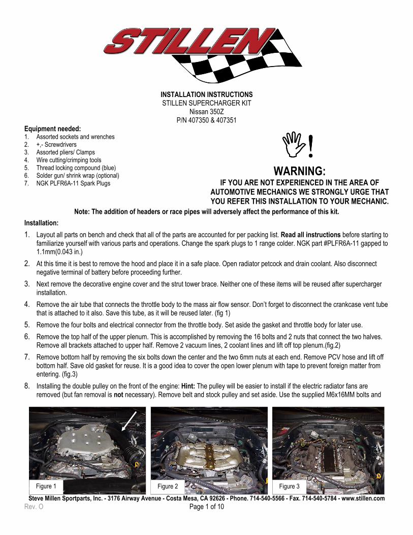
4. Remove the air tube that connects the throttle body to the mass air flow sensor. Don’t forget to disconnect the crankcase vent tube that is attached to it also. Save this tube, as it will be reused later. (fig 1)
5. Remove the four bolts and electrical connector from the throttle body. Set aside the gasket and throttle body for later use.
6. Remove the top half of the upper plenum. This is accomplished by removing the 16 bolts and 2 nuts that connect the two halves. Remove all brackets attached to upper half. Remove 2 vacuum lines, 2 coolant lines and lift off top plenum.(fig.2)
7. Remove bottom half by removing the six bolts down the center and the two 6mm nuts at each end. Remove PCV hose and lift off bottom half. Save old gasket for reuse. It is a good idea to cover the open lower plenum with tape to prevent foreign matter from entering. (fig.3)
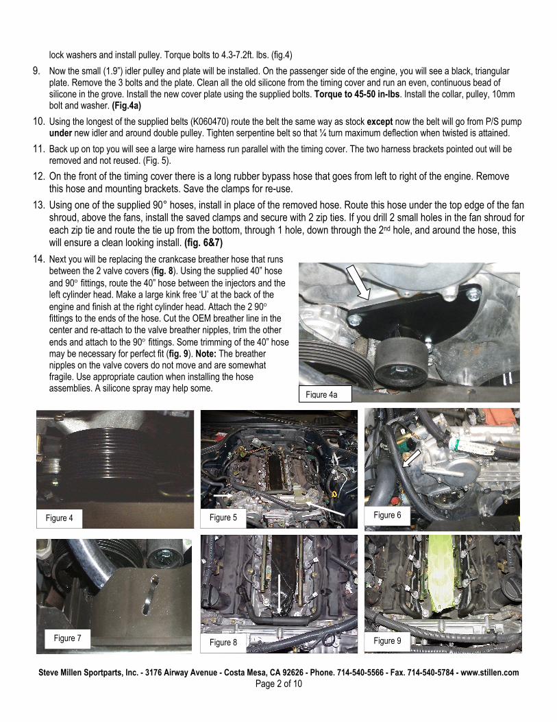
8. Installing the double pulley on the front of the engine: Hint: The pulley will be easier to install if the electric radiator fans are removed (but fan removal is not necessary). Remove belt and stock pulley and set aside. Use the supplied M6x16MM bolts and
Steve Millen Sportparts, Inc. - 3176 Airway Avenue - Costa Mesa, CA 92626 - Phone. 714-540-5566 - Fax. 714-540-5784 - www.stillen.com
Page 2 of 10
Figure 8
Figure 5
Figure 4
Figure 9
Figure 4a
Figure 6
Figure 7
lock washers and install pulley. Torque bolts to 4.3-7.2ft. lbs. (fig.4)
9. Now the small (1.9”) idler pulley and plate will be installed. On the passenger side of the engine, you will see a black, triangular plate. Remove the 3 bolts and the plate. Clean all the old silicone from the timing cover and run an even, continuous bead of silicone in the grove. Install the new cover plate using the supplied bolts. Torque to 45-50 in-lbs. Install the collar, pulley, 10mm bolt and washer. (Fig.4a)
10. Using the longest of the supplied belts (K060470) route the belt the same way as stock except now the belt will go from P/S pump under new idler and around double pulley. Tighten serpentine belt so that ¼ turn maximum deflection when twisted is attained.
11. Back up on top you will see a large wire harness run parallel with the timing cover. The two harness brackets pointed out will be removed and not reused. (Fig. 5).
12. On the front of the timing cover there is a long rubber bypass hose that goes from left to right of the engine. Remove this hose and mounting brackets. Save the clamps for re-use.
13. Using one of the supplied 90° hoses, install in place of the removed hose. Route this hose under the top edge of the fan shroud, above the fans, install the saved clamps and secure with 2 zip ties. If you drill 2 small holes in the fan shroud for each zip tie and route the tie up from the bottom, through 1 hole, down through the 2nd hole, and around the hose, this will ensure a clean looking install. (fig. 6&7)
14. Next you will be replacing the crankcase breather hose that runs between the 2 valve covers (fig. 8). Using the supplied 40” hose
and 90° fittings, route the 40” hose between the injectors and the left cylinder head. Make a large kink free ‘U’ at the back of the
engine and finish at the right cylinder head. Attach the 2 90° fittings to the ends of the hose. Cut the OEM breather line in the center and re-attach to the valve breather nipples, trim the other
ends and attach to the 90° fittings. Some trimming of the 40” hose may be necessary for perfect fit (fig. 9). Note: The breather nipples on the valve covers do not move and are somewhat fragile. Use appropriate caution when installing the hose assemblies. A silicone spray may help some.
Steve Millen Sportparts, Inc. - 3176 Airway Avenue - Costa Mesa, CA 92626 - Phone. 714-540-5566 - Fax. 714-540-5784 - www.stillen.com
Page 3 of 10
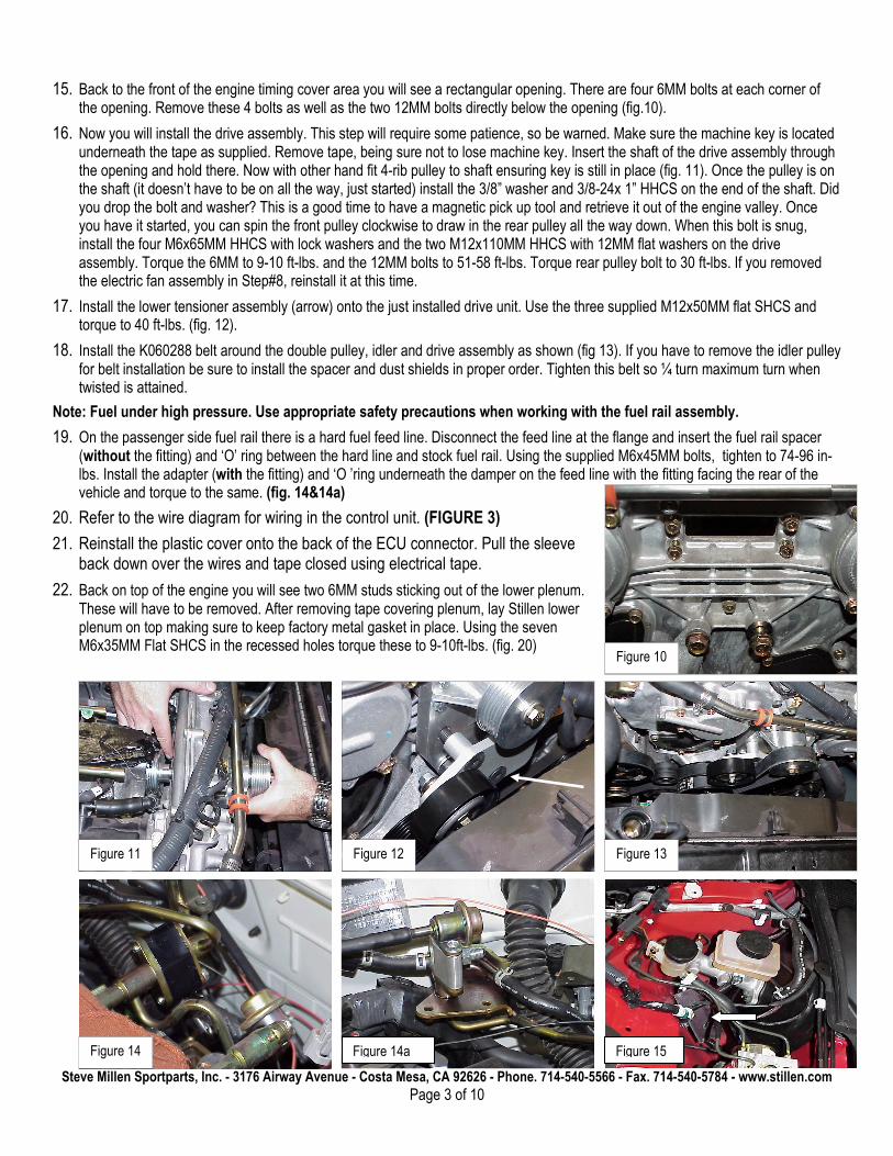
15. Back to the front of the engine timing cover area you will see a rectangular opening. There are four 6MM bolts at each corner of the opening. Remove these 4 bolts as well as the two 12MM bolts directly below the opening (fig.10).
16. Now you will install the drive assembly. This step will require some patience, so be warned. Make sure the machine key is located underneath the tape as supplied. Remove tape, being sure not to lose machine key. Insert the shaft of the drive assembly through the opening and hold there. Now with other hand fit 4-rib pulley to shaft ensuring key is still in place (fig. 11). Once the pulley is on the shaft (it doesn’t have to be on all the way, just started) install the 3/8” washer and 3/8-24x 1” HHCS on the end of the shaft. Did you drop the bolt and washer? This is a good time to have a magnetic pick up tool and retrieve it out of the engine valley. Once you have it started, you can spin the front pulley clockwise to draw in the rear pulley all the way down. When this bolt is snug, install the four M6x65MM HHCS with lock washers and the two M12x110MM HHCS with 12MM flat washers on the drive assembly. Torque the 6MM to 9-10 ft-lbs. and the 12MM bolts to 51-58 ft-lbs. Torque rear pulley bolt to 30 ft-lbs. If you removed the electric fan assembly in Step#8, reinstall it at this time.
17. Install the lower tensioner assembly (arrow) onto the just installed drive unit. Use the three supplied M12x50MM flat SHCS and torque to 40 ft-lbs. (fig. 12).
18. Install the K060288 belt around the double pulley, idler and drive assembly as shown (fig 13). If you have to remove the idler pulley for belt installation be sure to install the spacer and dust shields in proper order. Tighten this belt so ¼ turn maximum turn when twisted is attained.
Note: Fuel under high pressure. Use appropriate safety precautions when working with the fuel rail assembly.
19. On the passenger side fuel rail there is a hard fuel feed line. Disconnect the feed line at the flange and insert the fuel rail spacer (without the fitting) and ‘O’ ring between the hard line and stock fuel rail. Using the supplied M6x45MM bolts, tighten to 74-96 in-lbs. Install the adapter (with the fitting) and ‘O ’ring underneath the damper on the feed line with the fitting facing the rear of the vehicle and torque to the same. (fig. 14&14a)
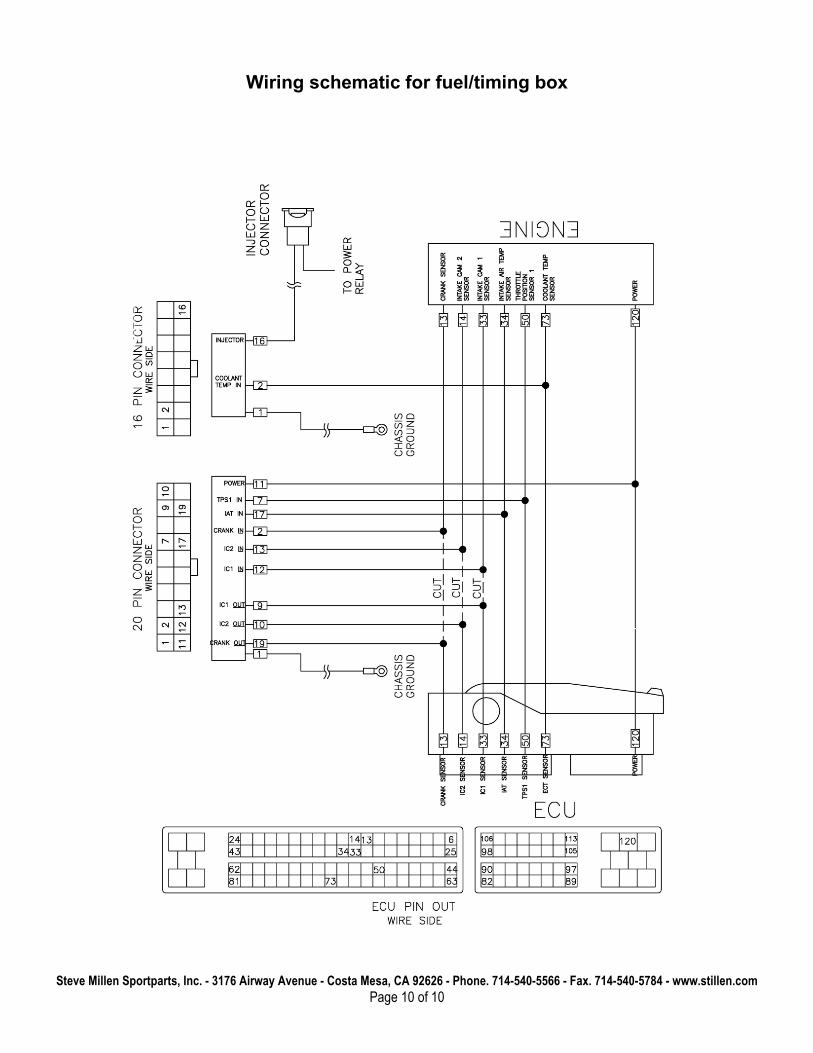
20. Refer to the wire diagram for wiring in the control unit. (FIGURE 3)
21. Reinstall the plastic cover onto the back of the ECU connector. Pull the sleeve back down over the wires and tape closed using electrical tape.
22. Back on top of the engine you will see two 6MM studs sticking out of the lower plenum. These will have to be removed. After removing tape covering plenum, lay Stillen lower plenum on top making sure to keep factory metal gasket in place. Using the seven M6x35MM Flat SHCS in the recessed holes torque these to 9-10ft-lbs. (fig. 20)
Figure 12 Figure 13
Figure 10
Figure 11
Figure 15 Figure 14 Figure 14a
Steve Millen Sportparts, Inc. - 3176 Airway Avenue - Costa Mesa, CA 92626 - Phone. 714-540-5566 - Fax. 714-540-5784 - www.stillen.com
Page 4 of 10
Figure 19
Figure 18
Figure 20 Figure 21
Figure 17 Figure 16
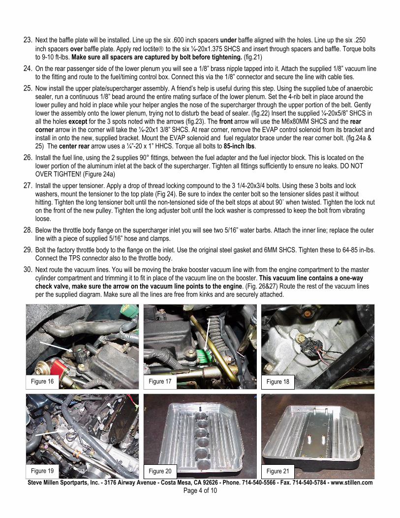
23. Next the baffle plate will be installed. Line up the six .600 inch spacers under baffle aligned with the holes. Line up the six .250 inch spacers over baffle plate. Apply red loctite to the six ¼-20x1.375 SHCS and insert through spacers and baffle. Torque bolts to 9-10 ft-lbs. Make sure all spacers are captured by bolt before tightening. (fig.21)
24. On the rear passenger side of the lower plenum you will see a 1/8” brass nipple tapped into it. Attach the supplied 1/8” vacuum line to the fitting and route to the fuel/timing control box. Connect this via the 1/8” connector and secure the line with cable ties.
25. Now install the upper plate/supercharger assembly. A friend’s help is useful during this step. Using the supplied tube of anaerobic sealer, run a continuous 1/8” bead around the entire mating surface of the lower plenum. Set the 4-rib belt in place around the lower pulley and hold in place while your helper angles the nose of the supercharger through the upper portion of the belt. Gently lower the assembly onto the lower plenum, trying not to disturb the bead of sealer. (fig.22) Insert the supplied ¼-20x5/8” SHCS in all the holes except for the 3 spots noted with the arrows (fig.23). The front arrow will use the M6x80MM SHCS and the rear corner arrow in the corner will take the ¼-20x1 3/8” SHCS. At rear corner, remove the EVAP control solenoid from its bracket and install in onto the new, supplied bracket. Mount the EVAP solenoid and fuel regulator brace under the rear corner bolt. (fig.24a & 25) The center rear arrow uses a ¼”-20 x 1” HHCS. Torque all bolts to 85-inch lbs.
26. Install the fuel line, using the 2 supplies 90° fittings, between the fuel adapter and the fuel injector block. This is located on the lower portion of the aluminum inlet at the back of the supercharger. Tighten all fittings sufficiently to ensure no leaks. DO NOT OVER TIGHTEN! (Figure 24a)
27. Install the upper tensioner. Apply a drop of thread locking compound to the 3 1/4-20x3/4 bolts. Using these 3 bolts and lock washers, mount the tensioner to the top plate (Fig 24). Be sure to index the center bolt so the tensioner slides past it without hitting. Tighten the long tensioner bolt until the non-tensioned side of the belt stops at about 90˚ when twisted. Tighten the lock nut on the front of the new pulley. Tighten the long adjuster bolt until the lock washer is compressed to keep the bolt from vibrating loose.
28. Below the throttle body flange on the supercharger inlet you will see two 5/16” water barbs. Attach the inner line; replace the outer line with a piece of supplied 5/16” hose and clamps.
29. Bolt the factory throttle body to the flange on the inlet. Use the original steel gasket and 6MM SHCS. Tighten these to 64-85 in-lbs. Connect the TPS connector also to the throttle body.
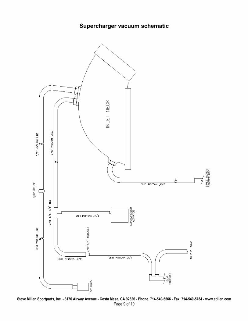
30. Next route the vacuum lines. You will be moving the brake booster vacuum line with from the engine compartment to the master cylinder compartment and trimming it to fit in place of the vacuum line on the booster. This vacuum line contains a one-way check valve, make sure the arrow on the vacuum line points to the engine. (Fig. 26&27) Route the rest of the vacuum lines per the supplied diagram. Make sure all the lines are free from kinks and are securely attached.
Steve Millen Sportparts, Inc. - 3176 Airway Avenue - Costa Mesa, CA 92626 - Phone. 714-540-5566 - Fax. 714-540-5784 - www.stillen.com
Page 5 of 10
Figure 22
Figure 23
Figure 27 Figure 26
Figure 24
Figure 25
Figure 24a
31. Now install the throttle body tube removed in step 4.Don’t forget to attach the crankcase vent hose to the throttle body tube. Tighten all hose clamps.
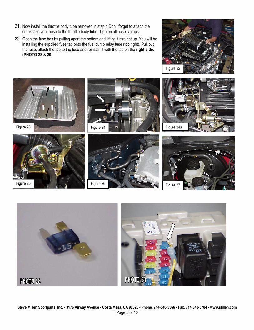
32. Open the fuse box by pulling apart the bottom and lifting it straight up. You will be installing the supplied fuse tap onto the fuel pump relay fuse (top right). Pull out the fuse, attach the tap to the fuse and reinstall it with the tap on the right side. (PHOTO 28 & 29)
Steve Millen Sportparts, Inc. - 3176 Airway Avenue - Costa Mesa, CA 92626 - Phone. 714-540-5566 - Fax. 714-540-5784 - www.stillen.com
Page 6 of 10
Fuel/timing control unit:
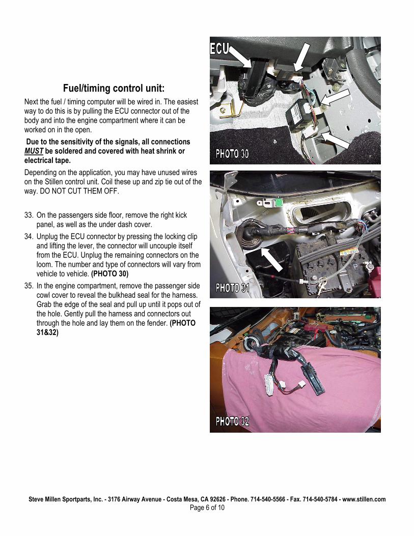
Next the fuel / timing computer will be wired in. The easiest way to do this is by pulling the ECU connector out of the body and into the engine compartment where it can be worked on in the open.
Due to the sensitivity of the signals, all connections MUST be soldered and covered with heat shrink or electrical tape.
Depending on the application, you may have unused wires on the Stillen control unit. Coil these up and zip tie out of the way. DO NOT CUT THEM OFF.
33. On the passengers side floor, remove the right kick panel, as well as the under dash cover.
34. Unplug the ECU connector by pressing the locking clip and lifting the lever, the connector will uncouple itself from the ECU. Unplug the remaining connectors on the loom. The number and type of connectors will vary from vehicle to vehicle. (PHOTO 30)
35. In the engine compartment, remove the passenger side cowl cover to reveal the bulkhead seal for the harness. Grab the edge of the seal and pull up until it pops out of the hole. Gently pull the harness and connectors out through the hole and lay them on the fender. (PHOTO 31&32)
Steve Millen Sportparts, Inc. - 3176 Airway Avenue - Costa Mesa, CA 92626 - Phone. 714-540-5566 - Fax. 714-540-5784 - www.stillen.com
Page 7 of 10
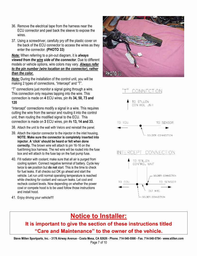
36. Remove the electrical tape from the harness near the ECU connector and peel back the sleeve to expose the wires.
37. Using a screwdriver, carefully pry off the plastic cover on the back of the ECU connector to access the wires as they enter the connector. (PHOTO 33)
Note: When referring to a pin-out diagram, it is always viewed from the wire side of the connector. Due to different models or vehicle options, wire colors may vary. Always refer to the pin number (wire location on the connector), rather than the color.
Note: During the installation of the control unit, you will be making 2 types of connections, “Intercept” and “T”.
“T” connections just monitor a signal going through a wire. This connection only requires tapping into the wire. This connection is made on 4 ECU wires, pin #s 34, 50, 73 and 120
“Intercept” connections modify a signal in a wire. This requires cutting the wire from the sensor and routing it into the control unit, then routing the modified signal to the ECU. This connection is made on 3 ECU wires, pin #s 13, 14 and 33.
38. Attach the unit to the wall with Velcro and reinstall the panel.
39. Attach the injector connector to the injector in the inlet housing. NOTE: Make sure the connector is completely inserted into injector. A ‘click’ should be heard or felt when done correctly. The brown wire will attach to pin 16-16 on the fuel/timing box harness. The red wire will be routed into the fuse box and will attach to the fuse tap on the fuel pump fuse.
40. Fill radiator with coolant; make sure that all air is purged from cooling system. Connect negative terminal of battery. Cycle key twice to on position but do not start. This is the time to check for fuel leaks. If all checks out OK go ahead and start the vehicle. Let run until normal operating temperature is reached while checking for coolant and vacuum leaks. Let cool and recheck coolant levels. Now depending on whether the power cowl or compete hood is to be used follow those instructions and install hood.
41. Enjoy driving your vehicle!!!!
Notice to Installer: It is important to give the section of these instructions titled
“Care and Maintenance” to the owner of the vehicle.
Steve Millen Sportparts, Inc. - 3176 Airway Avenue - Costa Mesa, CA 92626 - Phone. 714-540-5566 - Fax. 714-540-5784 - www.stillen.com
Page 8 of 10
CARE & MAINTENANCE:
The STILLEN supercharger is designed to be virtually maintenance free. The oil in the supercharger is designed to last 100,000 miles between changes. All bearings used are lubricated and sealed. However there are some basic care items that should be checked regularly.
• Always use the best fuel available for your vehicle. MINIMUM OF 91 OCTANE.
• IF FOR WHATEVER REASON THE VEHICLE STARTS TO PING OR DETONATE UNDER LOAD OR HIGH RPM GET OFF THE THROTTLE!
• Changing climate, altitude or atmospheric conditions will affect your vehicle. Various types of fuel (e.g. oxygenated, ethanol, etc) will also affect the performance of your vehicle.
• We recommend changing the spark plugs to 1 range colder. NGK part# PLFR6A-11 gapped to 1.1mm (0.043in.)
• Check the supercharger drive belts regularly. Replace any that show signs of cracking/tearing. Check coolant level in intercooler often. It should be changed annually to maintain peak performance.
• Check your air filter regularly. A clogged air filter can drastically affect your vehicle. A ‘drop in’ high performance air filter is acceptable. The addition of an “open element style” hi flow filter system may cause high noise levels.
• High quality synthetic oil is recommended and oil changes should be done every 3,000 miles. This improves engine durability and longevity in a forced induction application.
• Do not alter, modify or adjust the Stillen supercharger system in any way. Unauthorized changes to boost levels, electronics or any other system will void warranties and can cause catastrophic engine damage.
• The addition of headers or race pipes will adversely affect the performance of this kit.
Steve Millen Sportparts, Inc. - 3176 Airway Avenue - Costa Mesa, CA 92626 - Phone. 714-540-5566 - Fax. 714-540-5784 - www.stillen.com
Page 9 of 10
Supercharger vacuum schematic
Steve Millen Sportparts, Inc. - 3176 Airway Avenue - Costa Mesa, CA 92626 - Phone. 714-540-5566 - Fax. 714-540-5784 - www.stillen.com
Page 10 of 10
Wiring schematic for fuel/timing box