status report on the fair project - kekepaper.kek.jp/r08/talks/thaau02.pdf · status report on the...
TRANSCRIPT

Status Report on the FAIR project
Christina DIMOPOULOU
on behalf of FAIR Technical
Division,
GSI Accelerator Division & collaborators
....
RuPAC
2008, 28.09-3.10.08, Zvenigorod, Russia

FAIR accelerators
p-bar
target
p-linac
Super-
FRS
SIS100SIS300
HESR
CRRESR
Unilac
SIS 100
NESR
HESR
Antiproton Production Target
SIS18 Upgrade
CR
FAIR Baseline Layout
RESR
p-linac SIS 300
Accelerator
SuperFRSPANDA
Atomic Phys.
Plasma Phys. Low Energy Exp.
High Energy Exp.
NESR Exp.
FLAIR
Atomic Physics
HADES & CBM
Experiment
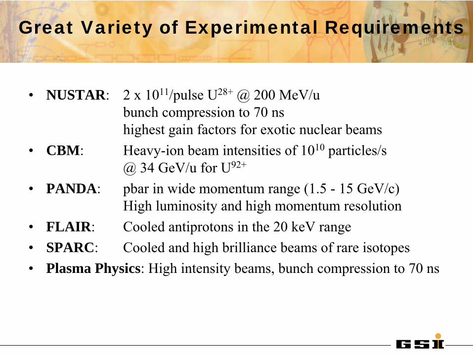
Great Variety of Experimental Requirements
•
NUSTAR: 2 x 10¹¹/pulse U28+
@ 200 MeV/u
bunch compression to 70 ns highest gain factors for exotic nuclear beams
•
CBM: Heavy-ion beam intensities of 1010
particles/s
@ 34 GeV/u for U92+
•
PANDA:
pbar in wide momentum range (1.5 -
15 GeV/c) High luminosity and high momentum resolution
•
FLAIR:
Cooled antiprotons in the 20 keV
range•
SPARC:
Cooled and high brilliance beams of rare isotopes
•
Plasma Physics: High intensity beams, bunch compression to 70 ns
100 m
UNILACSIS 18
SIS 100
HESR
SuperFRS
NESR
CR
RESR
FLAIR
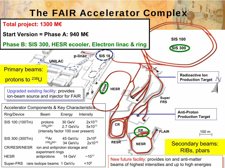
Accelerator Components
& Key CharacteristicsRing/Device
Beam
Energy Intensity
SIS 100 (100Tm) protons
30 GeV 2x10¹³
238U28+
2.7 GeV/u 5x10¹¹
(intensity
factor
100 over
present)
SIS 300 (300Tm) 40Ar 45 GeV/u 2x10⁹
238U92+
34 GeV/u 2x10¹⁰
CR/RESR/NESR ion
and antiproton
storage
and experiment
ringsHESR
antiprotons
14 GeV ~1011
Super-FRS
rare isotope
beams
1 GeV/u <109
Radioactive Ion Production Target
Anti-Proton Production Target
Upgraded existing facility: provides ion-beam source and injector for FAIR
Upgraded existing facility: provides ion-beam source and injector for FAIR
New future facility:
provides ion and anti-matterbeams of highest intensities and up to high energies
New future facility:
provides ion and anti-matterbeams of highest intensities and up to high energies
The FAIR Accelerator Complex
ER
SIS 300
p-linac
Secondary
beams: RIBs, pbars
Total project: 1300 M€
Start Version = Phase A: 940 M€
Phase B: SIS 300, HESR ecooler, Electron
linac
& ring
e-co
ol
Primary
beams:
protons
to 238U

FAIR Accelerator Challenges
1. Beam Intensity Frontier:Highest intensities for energetic heavy ion beams
⇒ 100-1000 times higher primary beam intensities than presently
2. Beam Brightness Frontier:Highest phase space densities
⇒ Compressed
and intense
primary beams⇒ Cooled
secondary beams: radioactive ions and antiprotons
Related Technical Challenges:control of intense, medium charge state heavy ion beams:
dynamic vacuum, space charge effects, collective instabilities beam cooling at medium/high energies: electron and stochastic coolingfast ramping superconducting magnetscompact rf cavities, complex rf manipulationsparallel operation of several beam and experiments

100 m
UNILACSIS 18
SIS 100
HESR
SuperFRS
NESR
CR
RESR
FLAIR
Radioactive Ion Production Target
Anti-Proton Production Target
The FAIR Accelerator Complex
ER
SIS 300
p-linac
Primary
beams:
protons
to 238U
Accelerator Components
& Key CharacteristicsRing/Device
Beam
Energy Intensity
SIS 100 (100Tm) protons
30 GeV 2x10¹³
238U28+
2.7 GeV/u 5x10¹¹
(intensity
factor
100 over
present)
SIS 300 (300Tm) 40Ar 45 GeV/u 2x10⁹
238U92+
34 GeV/u 2x10¹⁰
CR/RESR/NESR ion
and antiproton
storage
and experiment
ringsHESR
antiprotons
14 GeV ~1011
Super-FRS
rare isotope
beams
1 GeV/u <109
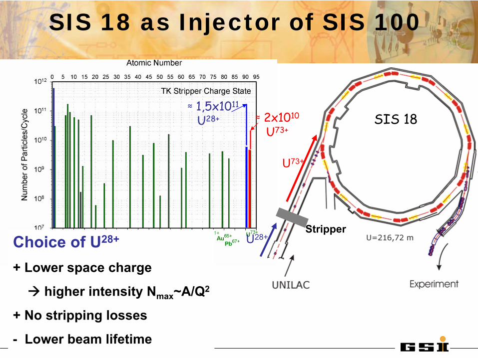
SIS 18 as Injector of SIS 100
≈
1,5x10¹¹
U28+ ≈
2x10¹⁰
U73+SIS 18
U28+Stripper
U73+
Choice
of U28+
+ Lower
space
charge
higher intensity Nmax~A/Q2
+ No stripping
losses
-
Lower
beam
lifetime
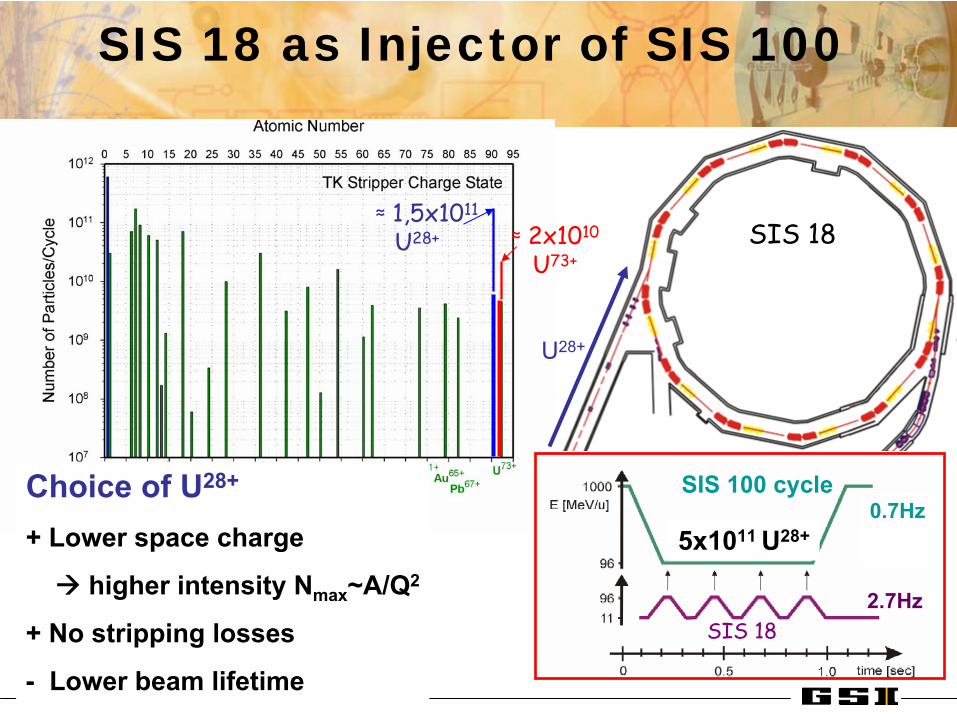
SIS 18 as Injector of SIS 100
≈
1,5x10¹¹
U28+ ≈
2x10¹⁰
U73+SIS 18
U28+
Choice
of U28+
+ Lower
space
charge
higher intensity Nmax~A/Q2
+ No stripping
losses
-
Lower
beam
lifetime
5x10¹¹ U28+
SIS 18
SIS 100 cycle
2.7Hz
0.7Hz

Control of Dynamic Vacuum Pressure in SIS 18
Main beam loss mechanism:U28+
-> U29+ (stripping)
dPdt
= τ p−1(P − P0) + αηlossNP
Dynamic pressure:
Desorption coefficient:
η =# desorbed molecules
# incident ions∝
dEdx
⎛ ⎝
⎞ ⎠
2
U28+
lifetime in SIS-18
1.8E10
8E960 % loss
270 ms
Goals:-
increase pumping speed
-
localize beam loss- minimize desorption- monitor with diagnostics
Measures:-NEG-coated chambers-Combined pumping/collimation ports behind dipoles
New!

beam
moveable
Absorbers:Cu bulk, Au coating
Secondary chamber
Control of Dynamic Vacuum Pressure in SIS 18

SIS 100 High-Intensity and Compressor Stage
Intermediate charge state ions e.g. U28+
ions up to 2.7 GeV/u
Protons up to 29 GeV
•
fast-ramped superconducting magnets
and •
strong bunch compression system
Bρ= 100 Tm Bmax
= 1.9 T dB/dt= 4 T/s (curved)
2D/3D field calculations 1st full-size
dipole
ready
for
testing!
Prototype production
also at BINP,JINR

SIS 100 Design Issues
SIS 100 lattice optimized for minimum dynamic vacuum beam
Minimum additional load
for
the
UHV and the
cryogenic
system.
Charge Separator
Doublet
Lattice
with
collimators
optimized
for
catching
efficiency
close
to 100% for
U29+
Wedge
collimator
(at 80 K) in secondary
chamber
with
enhanced
pumping, confines
most
of desorbed
gases
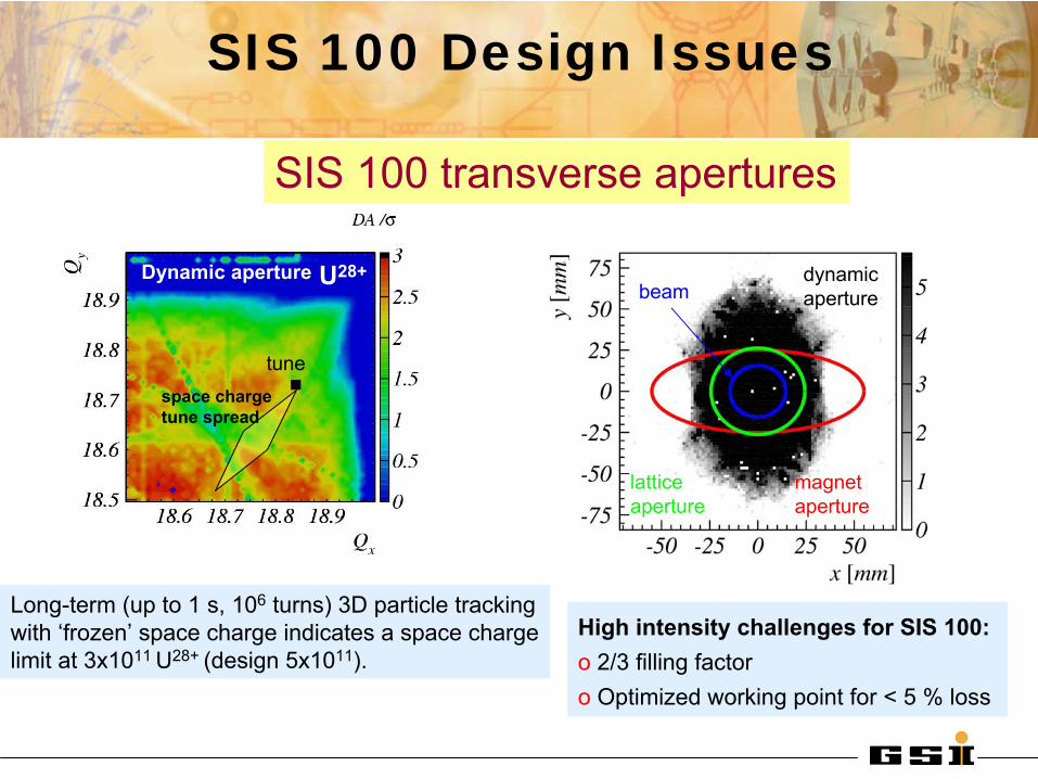
SIS 100 Design Issues
dynamic aperture
magnetaperture
lattice aperture
beam
High intensity challenges for SIS 100:o
2/3 filling factoro Optimized working point for < 5 % loss
Long-term (up to 1 s, 106
turns) 3D particle tracking with ‘frozen’
space charge indicates a space charge limit at 3x10¹¹ U28+ (design 5x10¹¹).
tunespace chargetune spread
Dynamic aperture U28+
SIS 100 transverse apertures
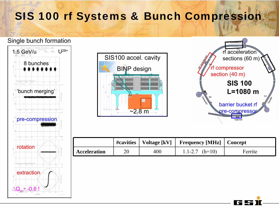
SIS 100 rf Systems & Bunch Compression
#cavities Voltage [kV] Frequency [MHz] Concept
Acceleration 20 400 1.1-2.7 (h=10) Ferrite
Single bunch formation
8 bunches
‘bunch merging’
pre-compression
rotation
extraction
1.5 GeV/u
∆Qsc
≈
-0.6 !
SIS 100L=1080 m
rf
accelerationsections (60 m)
barrier bucket rfpre-compressor
rf
compressorsection (40 m)
~2.8 m
SIS100 accel. cavity
BINP design
U28+

SIS 100 rf Systems & Bunch Compression
#cavities Voltage [kV] Frequency [MHz] ConceptPre-compression 2 15 1.5 MA (low duty cycle)
Single bunch formation
8 bunches
‘bunch merging’
pre-compression
rotation
extraction
1.5 GeV/u
∆Qsc
≈
-0.6 !
SIS 100L=1080 m
rf
accelerationsections (60 m)
barrier bucket rfpre-compressor
rf
compressorsection (40 m)
space charge reduces the effect of beam loading
Vlasov
simulation
no sc;
with
sc
Pre-compression
with
Barrier
bucket
rf
5 x10¹¹
U28+U28+
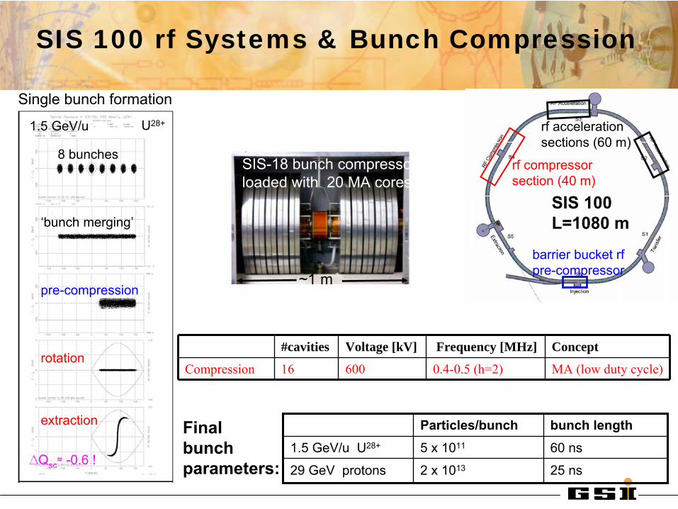
SIS 100 rf Systems & Bunch Compression
#cavities Voltage [kV] Frequency [MHz] Concept
Compression 16 600 0.4-0.5 (h=2) MA (low duty cycle)
Single bunch formation
8 bunches
‘bunch merging’
pre-compression
rotation
extraction
1.5 GeV/u
∆Qsc
≈
-0.6 !2 x 10¹³
5 x 10¹¹
Particles/bunch bunch length
25 ns29 GeV
protons
60 ns1.5 GeV/u
U28+
Final bunchparameters:
SIS 100L=1080 m
rf
accelerationsections (60 m)
barrier bucket rfpre-compressor
rf
compressorsection (40 m)
SIS-18 bunch compressor loaded with 20 MA cores
~1 m
U28+

SIS 300 High Energy and Stretcher Stage
Highly charged ions e.g. U92+
ions up to 34 GeV/u
Intermediate charge state e.g.
U28+
ions at 1.5 to 2.7 GeV/u with
100% duty cycle
•
superconducting high-field magnets and•
stretcher function
Bρ= 300 Tm Bmax
= 4.5 T dB/dt= 1 T/s (curved)
First cycling
sccosθ
magnet, BNL 2003
Model under
construction

100 m
UNILACSIS 18
SIS 100
HESR
SuperFRS
NESR
CR
RESR
FLAIR
Radioactive Ion Production Target
Anti-Proton Production Target
The FAIR Accelerator Complex
ER
SIS 300
p-linac
Secondary
beams: RIBs, pbars
Accelerator Components
& Key CharacteristicsRing/Device
Beam
Energy Intensity
SIS 100 (100Tm) protons
30 GeV 2x10¹³
238U28+
2.7 GeV/u 5x10¹¹
(intensity
factor
100 over
present)
SIS 300 (300Tm) 40Ar 45 GeV/u 2x10⁹
238U92+
34 GeV/u 2x10¹⁰
CR/RESR/NESR ion
and antiproton
storage
and experiment
ringsHESR
antiprotons
14 GeV ~1011
Super-FRS
rare isotope
beams
1 GeV/u <109
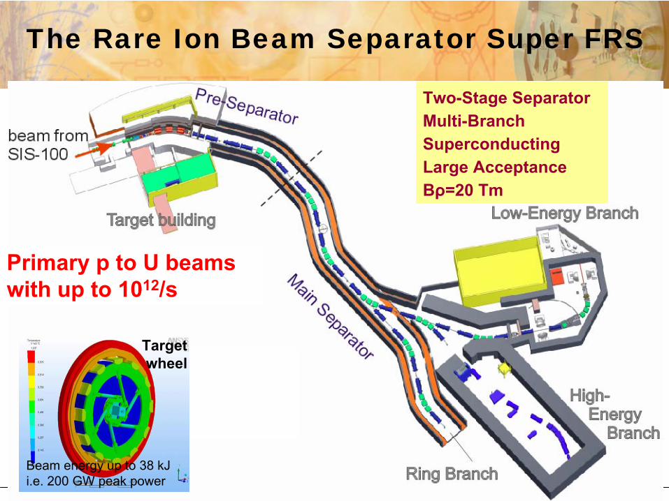
Primary
p to U beamswith
up to 1012/s
Beam energy up to 38 kJ i.e. 200 GW peak power
Targetwheel
The Rare Ion Beam Separator Super FRS
Two-Stage Separator Multi-BranchSuperconducting Large AcceptanceBρ=20 Tm

Rate after
target
for
1012/s primary
ions
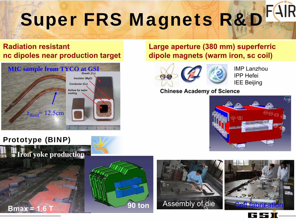
Prototype (BINP)
Iron yoke production
Bmax = 1.6 T
Radiation resistant nc
dipoles near production target
rBend
= 12.5cm
MIC sample from TYCO at GSI
Super FRS Magnets R&D
IMP LanzhouIPP HefeiIEE Beijing
Large aperture (380 mm) superferric dipole
magnets (warm iron, sc coil)
Chinese Academy of Science
Assembly
of die Coil
fabrication90 ton

The FAIR 13 Tm Storage Rings Normal conducting magnets
Electron
Ring ER
New ExperimentalStorage Ring
NESR
Collector Ring
CR
Accumulator Ring
RESR
to FLAIRionspbar
to HESR
pbar
from SuperFRSRIBs
from pbar
target
pbar
and RIB fast stochastic
pre-cooling
pbar
accumulation(RIB deceleration)
experiments with stored ions
pbar
and ion deceleration
ecool
e- linac
EoI
MagnetsBINPEoI
Kickers
IMP Lanzhou

Stochastic Cooling Developments
vacuum tankwith movable electrodes including cold heads (20 K) andcooled pre-amplifiers
prototype
electrode (ß
= 0.83-0.97)CR: fast stochastic cooling (1-2 GHz) of antiprotons (10 s) and RIBs
(1.5 s)
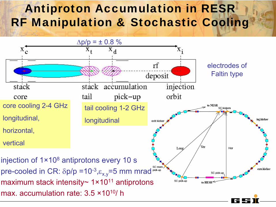
Antiproton Accumulation in RESR RF Manipulation & Stochastic Cooling
injection of 1×10⁸
antiprotons every 10 spre-cooled in CR: δp/p
=10-3,εx,y
=5 mm mradmaximum stack intensity~ 1×10¹¹
antiprotonsmax. accumulation rate: 3.5 ×10¹⁰/ h
core cooling 2-4 GHz
longitudinal,
horizontal,
vertical
tail cooling 1-2 GHz
longitudinal
electrodes of Faltin
type
Δp/p = ±
0.8 %

Specific
RF systemsPowerful
electron
cooling
UHV: pressure
≤
10-11
mbar
Key components:
high magnetic
field
qualitywithin
large aperture
for
large acceptance
Civil construction planning
Experimentsexperiments with internal targetelectron target (2nd electron cooler)laser interactions (cooling,spectroscopy)
collider
mode with e-
/ pbar
(bypass)
Ions (Stable & Rare Isotopes)
storage and e-cooling in the range740 → 4 MeV/u
(decel. rate ≤
1 T/s)
RIB stacking assisted by el.cooling
Antiprotons
deceleration 3000 → 800 → 30 MeVelectron cooling at 800 MeV
NESR: Versatile Operation
BINP
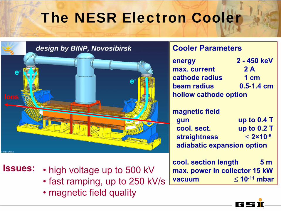
• high voltage up to 500 kV• fast ramping, up to 250 kV/s• magnetic field quality
Issues:
The NESR Electron Cooler
design by BINP, Novosibirsk
Ions
e-
e-
Cooler Parametersenergy 2 -
450 keV
max. current 2 Acathode radius 1 cmbeam radius 0.5-1.4 cmhollow cathode option
magnetic field gun up to 0.4 Tcool. sect. up to 0.2 Tstraightness ≤
2×10⁻⁵
adiabatic expansion option
cool. section length 5 mmax. power in collector 15 kW vacuum ≤
10-11
mbar

Electron Cooling in the NESR
0.0 0.2 0.4 0.6 0.8 1.01E-3
0.01
0.1
1
emitt
ance
(mm
mra
d)
t (s)
horizontal vertical
0 20 40 60 801E-4
1E-3
0.01
0.1
1
10
vertical horizontal
emitt
tanc
e (m
m m
rad)
t (s)
0 20 40 60 801E-6
1E-5
1E-4
1E-3
Δp/
p
t (s)
0.0 0.2 0.4 0.6 0.8 1.01E-6
1E-5
1E-4
1E-3
Δp/p
t (s)
132Sn50+ 740 MeV/u
108
ions Ie=1 A re=0.75 cm B=0.2 T
Antiprotons 800 MeV
108
ions Ie=2 A! re=1 cm B=0.2 T
tcool
< 1 s profit
of SIS100 cycle
!
BETACOOL SimulationsParkhomchuk
ecool
model
;Martini IBS model
ne=1.4 108 cm-3 ne=1.6 108 cm-3
tcool
~ 1-2 min !
Initial parameters: stochastic
pre-cooling
in CR (& RESR)
3rel
53ce
2
cool игвLn
Aq
ф1
⋅∝
-2
-1.5
-1
-0.5
0
0.5
1
1.5
2
-0.4 -0.2 0 0.2 0.4-3
-2
-1
0
1
2
3
ΔE [
MeV
]
V [
kV]
τ [μsec]
# p tau [sec] Energy [eV] at 2.000000e+00 [s] Cooling
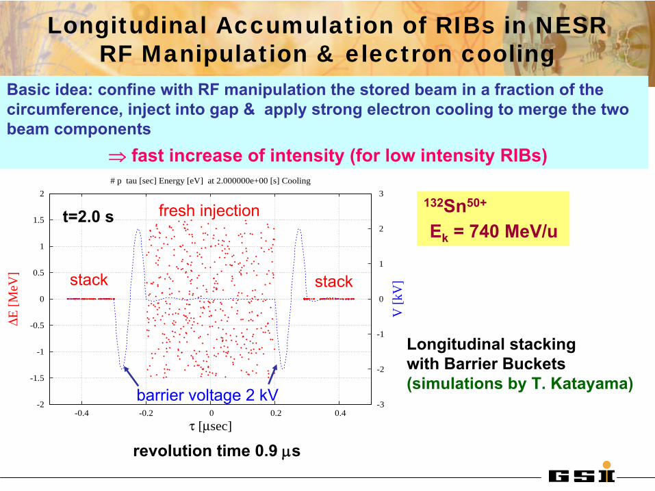
t=2.0 s
Longitudinal stackingwith Barrier Buckets(simulations by T. Katayama)
Longitudinal Accumulation of RIBs in NESR RF Manipulation & electron cooling
132Sn50+
Ek
= 740 MeV/u
revolution time 0.9 μs
barrier voltage 2 kV
Basic idea: confine with RF manipulation the stored beam in a fraction of the circumference, inject into gap & apply strong electron cooling to merge the two beam components
⇒ fast increase of intensity (for low intensity RIBs)
fresh injection
stack stack

Proof of Principle in the ESR
0 10 20 30 40 50 60 70 80 90 1000
1x10⁸
2x10⁸
3x10⁸
4x10⁸
5x10⁸
Stacking with Barrier Buckets: Vrf=120 V, frf= 5 MHz, Ie=0.1 A
Sta
cked
ES
R in
tens
ity
t (s)
all three schemes worked well: cooling times close to expectations
efficient accumulation high quality timing and kicker pulses required
Intensity limits: RF voltage and instabilities
t=0
0.25 s0.35 s
0.85 s
1.25 s
1.5 s
~1.2 sinjection
Trev
= 1μs
moving barriers
V=200 V
700 ns 124Xe54+
154 MeV/u
200
turn
s
V=120 V
fixed barriers h=1 unstable fixed point
1000 ns
40Ar18+
65 MeV/u
stack
40Ar18+
65 MeV/u
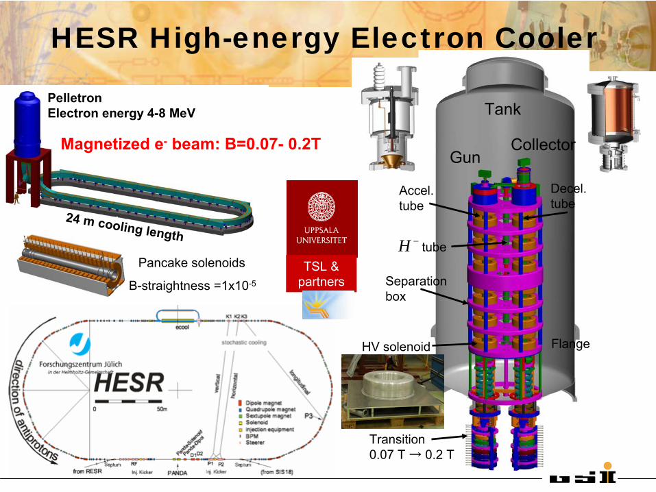
24 m cooling length
PelletronElectron energy 4-8 MeV
Collector
Decel. tube
HV solenoid
Gun
Accel. tube
Transition 0.07 T → 0.2 T
Flange
Tank
Separation box
tube−HPancake
solenoids
B-straightness
=1x10⁻⁵
HESR High-energy Electron Cooler
Magnetized
e-
beam: B=0.07-
0.2T
TSL & partners
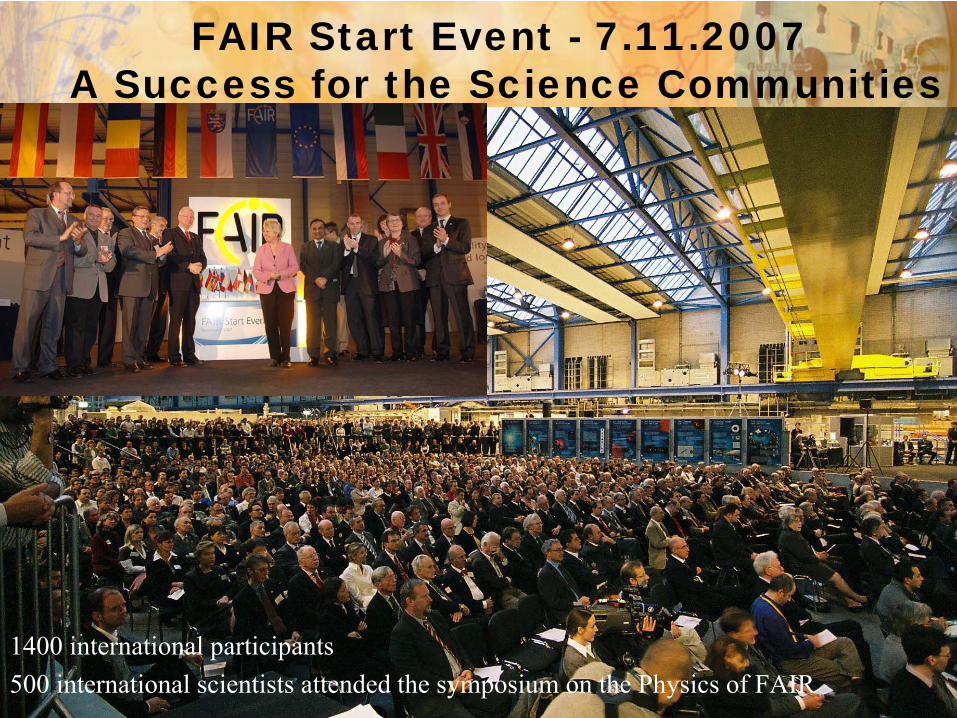
FAIR Start Event - 7.11.2007 A Success for the Science Communities
1400 international participants500 international scientists attended the symposium on the Physics of FAIR
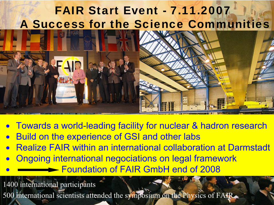
FAIR Start Event - 7.11.2007 A Success for the Science Communities
1400 international participants500 international scientists attended the symposium on the Physics of FAIR
∙
Towards a world-leading facility for nuclear & hadron research∙
Build on the experience of GSI and other labs
∙
Realize FAIR within an international collaboration at Darmstadt∙
Ongoing international negociations
on legal framework
∙
Foundation of FAIR GmbH end of 2008

in 2016
Thank you !
Austria
China Finland
France Germany Greece
India
Italy
Poland Slovenia
Spain Sweden
Romania
Russia
UK
Observers:Observers:

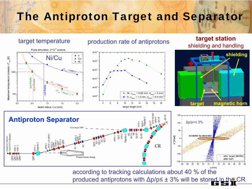
The Antiproton Target and Separator
Antiproton Separator
according to tracking calculations about 40 % of the produced antiprotons with Δp/p≤
±
3% will be stored in the CR
production rate of antiprotons target temperature target station shielding and handling
target magnetic horn
shieldingNi/Cu
Δp/p=±
3%
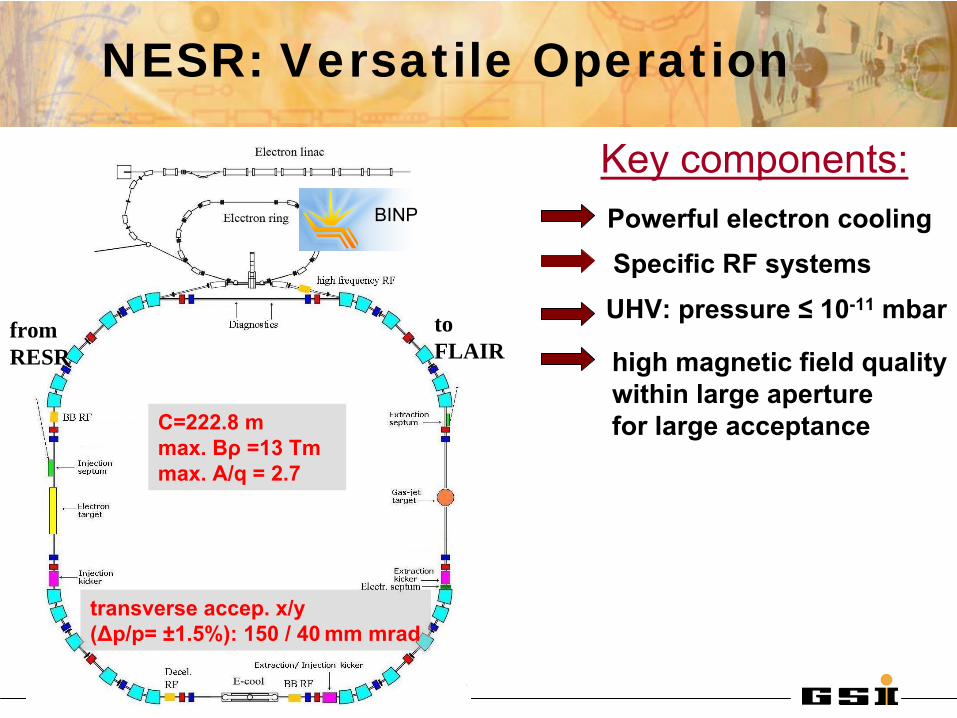
NESR: Versatile Operation
Specific
RF systemsPowerful
electron
cooling
UHV: pressure
≤
10-11
mbar
Key components:
high magnetic
field
qualitywithin
large aperture
for
large acceptance
to FLAIR
fromRESR
C=222.8 mmax. Bρ
=13 Tmmax. A/q = 2.7
transverse accep. x/y(Δp/p= ±1.5%):
150 / 40
mm mrad
BINP

0102030405060708090
100
10 60 110 160 210
Proton Linac Energy [MeV]
p-D
uty
SIS1
00 [%
], C
oole
d pb
ar
Rat
e [1
0^9/
h]
0
5
10
15
20
25
30
SIS18 Space Charge Lim
it [10^12]
SIS100 Duty Time
Cooled pbar / h
SIS18 SpaceCharge Limit
The proton Linac
Linac
lengthBeam current Beam pulse lengthRep. rate; rf
frequencyBeam powerrf
powerTot. normal. εx
; δp/p
≈
35 m35 mA; 70 mA (design) 36 µs4
Hz ; 325.2 MHz5 MW (peak), 710 W (average)11 MW (peak), 1600 W (average)
95 keV 3 MeV 70 MeV
Source LEBT RFQ CH-DTLRe-Buncher
to Dump
to SIS18ECR
Final rate of cooled pbar depends on injector energy:
70 MeV
Messing
Aluminium
Crossed-bar H-Cavity (CH)
Univ. Frankfurt