statement of work (sow) department of veterans …
TRANSCRIPT
STATEMENT OF WORK (SOW)
DEPARTMENT OF VETERANS AFFAIRS
Office of Information & Technology Hines Information Technology Center
Access Flooring and Substructure System Upgrade Project
Date: March 2016 CFM-16-N-0132
SOW Revision # 6
Access Flooring System Upgrade Project CFM Number: <CFM-16-N-0132>
Page 2 of 37
Access Flooring System Upgrade Project SOW v1.0
Contents 1.0 BACKGROUND ..................................................................................................... 3 2.0 APPLICABLE DOCUMENTS ................................................................................ 3 3.0 SCOPE OF WORK ................................................................................................ 3 4.0 PERFORMANCE DETAILS ................................................................................... 4
4.1 PERFORMANCE PERIOD................................................................................. 4 4.2 PLACE OF PERFORMANCE ............................................................................. 5 4.3 TRAVEL ............................................................................................................. 6 4.4 CHANGES TO STATEMENT OF WORK AND CONTRACT ............................. 6 4.5 materials delivery, storage and handling ............................................................ 6 4.6 CONTRACTOR QUALIFICATION REQUIREMENTS ........................................ 6
5.0 SPECIFIC TASKS AND DELIVERABLES ............................................................. 6 5.1 PROJECT MANAGEMENT ................................................................................ 6
5.1.1 CONTRACTOR PROJECT MANAGEMENT PLAN ..................................... 6 5.1.2 REPORTING REQUIREMENTS ................................................................. 7
5.2 COMPUTER ROOM ACCESS FLOORING AND UNDERSTRUCTURE SUPPORT SYSTEM REMOVALS, NEW INSTALLATIONS, AND RELATED WORK MODIFICATIONS ........................................................................................................ 7
5.2.1 Remove Selected Area Existing Access Flooring and Understructure Support System ........................................................................................................ 7 5.2.2 Install New Access Flooring and Understructure Support System ............... 7 5.2.3 Flooring Removal and New Install Impacts and Coordination ..................... 8 5.2.4 Spare Parts and Attic Inventory ................................................................... 8 5.2.5 Testing and User Acceptance of Access Flooring System .......................... 9 5.2.6 Customer Training ....................................................................................... 9 5.2.7 System and Installation Warranty ................................................................ 9 5.2.8 System Documentation and O&M Manuals ................................................. 9
6.0 GENERAL REQUIREMENTS ............................................................................. 10 6.1 ENTERPRISE AND IT FRAMEWORK ............................................................. 10 N/A ............................................................................................................................. 10 6.2 POSITION/TASK RISK DESIGNATION LEVEL(S) AND CONTRACTOR PERSONNEL SECURITY REQUIREMENTS ............................................................ 10
6.2.1 POSITION/TASK RISK DESIGNATION LEVEL(S) ................................... 10 6.2.2 CONTRACTOR PERSONNEL SECURITY REQUIREMENTS ................. 11
6.3 METHOD AND DISTRIBUTION OF DELIVERABLES ..................................... 13 6.4 PERFORMANCE METRICS ............................................................................ 13 6.5 FACILITY/RESOURCE PROVISIONS ............................................................. 13 6.6 GOVERNMENT FURNISHED PROPERTY ..................................................... 14
ADDENDUM A .............................................................................................................. 15 ADDENDUM B .............................................................................................................. 20 ADDENDUM C .............................................................................................................. 21 ADDENDUM D .............................................................................................................. 35
Access Flooring System Upgrade Project CFM Number: <CFM-16-N-0132>
Page 3 of 37
Access Flooring System Upgrade Project SOW v1.0
ADDENDUM E .............................................................................................................. 37
1.0 BACKGROUND The mission of the Department of Veterans Affairs (VA), Office of Information & Technology (OIT), Data Center Operations (DCO) is to provide benefits and services to Veterans of the United States. In meeting these goals, OIT, DCO strives to provide high quality, effective, and efficient Information Technology (IT) services to those responsible for providing care to Veterans at main hospital campuses as well as throughout Community Based Outpatient Clinics (CBOC’s) located throughout the United States, in an effective, timely and compassionate manner. VA depends on Information Management/Information Technology (IM/IT) systems to further meet mission goals. In order to accomplish the mission and goals of the Department of Veterans Affairs Hines Information Technology Center (VA-HITC) needs to upgrade existing Data Center Operation (DCO) facility computer room area where Information Technology (IT) productivity equipment’s are located. In order to keep DCO information technology (IT) center operational at Hines ITC computer room without facility maintenance related disruptions it is necessary to replace existing flooring and substructure. Existing flooring and substructure are showing deterioration and end sign of life expectancy cycle.
2.0 APPLICABLE DOCUMENTS In the performance of the tasks associated with this Performance Work Statement, the Contractor shall comply with the following:
1. 44 U.S.C. § 3541, “Federal Information Security Management Act (FISMA) of 2002”
2. Federal Information Processing Standards (FIPS) Publication 140-2, “Security Requirements For Cryptographic Modules”
3. 5 U.S.C. § 552a, as amended, “The Privacy Act of 1974” 4. 42 U.S.C. § 2000d “Title VI of the Civil Rights Act of 1964” 5. Department of Veterans Affairs (VA) Directive 0710, “Personnel Suitability
and Security Program,” May 18, 2007
3.0 SCOPE OF WORK The overall goal of the project is to remove existing access flooring and substructure, install new access flooring and substructure without operational disturbance to IT computer room equipment during ongoing project work. Contractor shall disconnect any hangers support connected to access flooring structure and install new independent supports as required (electrical conduit, power outlets, steam and chill water pipes, etc.). The Contractor shall provide all necessary materials, parts, labor, tools, equipment and supervision to perform work related to removal of existing access flooring system and
Access Flooring System Upgrade Project CFM Number: <CFM-16-N-0132>
Page 4 of 37
Access Flooring System Upgrade Project SOW v1.0
installation of new access flooring system at the Hines Information Technology Center computer room. Access flooring is to consist of a series of modular, removable, interchangeable 24” x 24” panels with other standard field panels on an elevated support system forming an accessible underfloor cavity to accommodate utilities such as electrical, data, telecommunication, mechanical system services, etc. Access flooring system shall be gravity-held panels on bolted stringer understructure and can be easily relocated by one person using a lifting device without disturbing adjacent panels and substructure. Installed panels with floor covering in place are to be free of exposed metal edges. This project Scope of Work (SOW) also includes related work such as repair of subflooring, walls, removal of existing access flooring and elevated support system (stringer, pedestal, pedestal head, base, base adhesive, ramps, steps, guard rails system, CRAC unit supply air registers/grilles), Installation of new access flooring on elevated support system (access panels with high pressure laminated covering, fabricated cut-outs floor panel with grommet, ramps and steps, railing and posts, perforated panels, pedestal, pedestal base and head, base adhesive, bolted stringer, CRAC unit supply Air Flow Panel). Contractor shall be responsible to ensure that there is a cable/wire slack to allow for lifting of the rack cabinets. Contractor shall be responsible to provide recyclable and disposable trash containers and services. Contractor shall be responsible to maintain record of connected power and data cable on each equipment rack and provide copy to COR before proceeding with any rack lifting procedure to perform access flooring work below the rack system. The contractor shall be working inside VA-HITC facility operational computer room. Contractor shall be responsible to prepare project drawings showing details of product installation and each phase work schedule with start and completion dates, material and equipment storage plan, hoisting of computer room IT equipment rack plan and submit to HITC COR for approval. Contractor shall provide phasing plan and drawings within 30 working days of notice to proceed. This contract is designed to be all inclusive of services, materials, support and warranty. Task and area where the VA is responsible are specifically called out within the SOW and the associated addendums.
4.0 PERFORMANCE DETAILS
4.1 PERFORMANCE PERIOD The total period of performance of this contract shall be not more than 270 calendar days after issuance of Notice to Proceed (NTP). The contractor shall obtain a minimum of six (6) employees with security clearances and PIV Badges to mitigate issues with authorized access into the computer room.
Access Flooring System Upgrade Project CFM Number: <CFM-16-N-0132>
Page 5 of 37
Access Flooring System Upgrade Project SOW v1.0
Any work at the Government site shall not take place on Federal holidays or weekends unless directed by the Contracting Officer (CO). If required, the CO may designate the Contractor to work during holidays and weekends. The work must be performed during “after” normal business hours (Monday – Friday) 1600 hrs. to 0700hrs. or weekends. Coordination and exceptions to this schedule shall be presented in writing and approved in advance by the COR. There are ten (10) Federal holidays set by law (USC Title 5 Section 6103) that VA follows: Under current definitions, four 4) are set by date: New Year's Day January 1 Independence Day July 4 Veterans Day November 11 Christmas Day December 25 If any of the above falls on a Saturday, then Friday shall be observed as a holiday. Similarly, if one falls on a Sunday, then Monday shall be observed as a holiday. The other six are set by a day of the week and month: Martin Luther King's Birthday Third Monday in January Washington's Birthday Third Monday in February Memorial Day Last Monday in May Labor Day First Monday in September Columbus Day Second Monday in October Thanksgiving Fourth Thursday in November
4.2 PLACE OF PERFORMANCE Tasks under this SOW shall be performed at the Hines ITC, 1st Avenue North of 22nd Street, Building 215, Hines, Illinois 60141. The following work may be performed at remote locations: billing activities, coordination of onsite work and scheduling, documentation reports without prior approval of the COR. Computer room is located on first floor of Hines Information Technology Center two story combined data center and office building. The computer room is approximately 14800 sqft of the total building space. See Addendum E for some a basic computer room layout information drawing. Contractor is allowed to visit site to perform inspection. Full size printed computer room drawing can be provided during site visit or by written request.
Access Flooring System Upgrade Project CFM Number: <CFM-16-N-0132>
Page 6 of 37
Access Flooring System Upgrade Project SOW v1.0
4.3 TRAVEL Not applicable to this contract.
4.4 CHANGES TO STATEMENT OF WORK AND CONTRACT Any changes to this SOW and associated tasks shall be authorized and approved through written correspondence from the Contracting Officer (CO). A copy of each change will be kept in a project folder along with all other products of the project. Costs incurred by the contractor through the actions of parties other than the CO shall be borne by the Contractor.
4.5 MATERIALS DELIVERY, STORAGE AND HANDLING
A. The Contractor shall keep the project materials in a secure location, as the Contractor is solely responsible for the safety and security of the materials until final acceptance by the Government.
B. The contractor shall ensure all materials are inspected for satisfactory condition upon delivery at the project site. Requests for deliveries to the HITC’s loading dock must be coordinated with the HITC Warehouse Team. The HITC warehouse team will not accept deliveries on behalf of the contractor. The contractor must be present to accept any delivery or it will be turned away. With proper notification to the COR and warehouse team exceptions can be made but the government shall not be responsible for the condition of the package when acceptance from the shipper is made.
4.6 CONTRACTOR QUALIFICATION REQUIREMENTS The Contractor and all employees shall meet requirements as specified in scope of work (SOW) document and Addendum C.
5.0 SPECIFIC TASKS AND DELIVERABLES
5.1 PROJECT MANAGEMENT 5.1.1 CONTRACTOR PROJECT MANAGEMENT PLAN The Contractor shall deliver a Contractor Project Management Plan (CPMP) for each phase of work that lays out the Contractor’s approach, timeline and tools to be used in execution of the contract. The CPMP should take the form of both a narrative and graphic format that displays the schedule, milestones, risks and resource support. The initial baseline CPMP shall be concurred upon and updated monthly thereafter. The Contractor shall update, maintain and deliver to the VA PM the approved CPMP throughout the period of performance. One (1) copy of the CPMP shall be delivered before the notice to proceed is issued.
Access Flooring System Upgrade Project CFM Number: <CFM-16-N-0132>
Page 7 of 37
Access Flooring System Upgrade Project SOW v1.0
5.1.2 REPORTING REQUIREMENTS The Contractor shall provide the Contracting Officer’s Representative (COR) with Biweekly Progress Reports in electronic form in Microsoft Word and Project formats. The report shall include detailed instructions/explanations for each required data element, to ensure that data is accurate and consistent. These reports shall reflect data as of the last day of the preceding two week period. The Biweekly Progress Reports shall cover all work completed during the reporting period and work planned for the subsequent reporting period. The report shall also identify any problems that arose and a description of how the problems were resolved. If problems have not been completely resolved, the Contractor shall provide an explanation including their plan and timeframe for resolving the issue. The Contractor shall monitor performance against the CPMP and report any deviations. It is expected that the Contractor will keep in communication with VA accordingly so that issues that arise are transparent to both parties to prevent escalation of outstanding issues.
5.2 COMPUTER ROOM ACCESS FLOORING AND UNDERSTRUCTURE SUPPORT SYSTEM REMOVALS, NEW INSTALLATIONS, AND RELATED WORK MODIFICATIONS
5.2.1 Remove Selected Area Existing Access Flooring and Understructure
Support System
A. Contractor shall remove existing access flooring and understructure support system and perform related work (removal of ramps and steps, railing and posts, adhesive, repair sub-flooring, dry wall, disconnect hanger support connected to existing understructure, etc.) per approved phases of work plan by project PM and COR. Contractor shall remove any disassembled access flooring and understructure support system material from work area at end of work day and dispose in appropriate disposal container (recycle or dispose) and maintain recycle and disposable material record. Contractor is responsible to maintain environmental friendly work area (dust and odor), if required provide portable HEPP air cleaner in work area.
B. See Addendum C for specific information on demolition and removal techniques and requirements.
5.2.2 Install New Access Flooring and Understructure Support System
A. Contractor shall provide and install access flooring panels, understructure supports (Stringer, Pedestal, adhesive, etc.), ramps and steps, railing and posts
Access Flooring System Upgrade Project CFM Number: <CFM-16-N-0132>
Page 8 of 37
Access Flooring System Upgrade Project SOW v1.0
and independent hanger support for under floor utilities per phase of work plan approved by project PM and COR. Material, tools and equipment required to perform each phase of work will be allowed to kept on VA-HITC assigned site, additional material shall be kept off-site storage facility with proper condition. VA-HITC will consider contractor written request for on-site container storage.
B. Contractor shall replace existing carpeted floor covering floor panel with new high pressure laminated floor covering floor panel. Access floor panel shall be interchangeable gravity-held panel on bolted stringer substructure. Access flooring shall be able to meet loading requirements (ultimate, concentrated /static, impact and rolling).Substructure support system element such as pedestal assembly, stringer shall be capable of withstanding the axial-loads, overturning moment, concentrated-load and stresses. Substructure support system assembly shall provide a mean to level and lock at selected height and prevent vibration displacement, stabilize pedestal base flooring and base mounting and stringer connection. Floor assembly to be rigid, free of vibration, rocking panels, rattles and squeaks. Air leakage through the joints between panels and around the perimeter of the floor system should not industry standard. Entire floor system shall be connected for safe continuous electrical grounding. Entire floor shall be static electric control. Substructure support system assembly shall be test before access flooring panel is place. Entire flooring shall be tested for electrical grounding and static electricity control.
C. All access flooring and substructure products installed shall meet requirements in Addendum C.
D. See Addendum C for specific information on installation techniques and
requirements.
5.2.3 Flooring Removal and New Install Impacts and Coordination The contractor shall coordinate each phase of work impacts with surrounding area existing condition such as subfloor electrical conduits, data cable, steam and chill water piping and on floor computer room IT equipment before proceeding with removal of existing access flooring and substructure support disassembly work. Contractor shall survey each IT operational equipment rack and keep record of each rack cable connection before any work performed under operational rack area. Contractor shall work with the VA-HITC project COR to determine areas best suited in the beginning of the project so that work phase plan can minimize impact to the computer room operation. 5.2.4 Spare Parts and Attic Inventory
A. Contractor shall supply attic stock for all parts and equipment installed within HITC. The following is a list of quantities and items:
Access Flooring System Upgrade Project CFM Number: <CFM-16-N-0132>
Page 9 of 37
Access Flooring System Upgrade Project SOW v1.0
i Access Floor Panel - 2% of total panel. ii Cut-Out Access Floor Panel with 4”x4” grommets - 5% of total cut-out panel. iii Perforated Panels with 25% open area - 5% of total panel. iv Pedestals – 2% of total pedestals. v Stringers – 2% of total stringers
5.2.5 Testing and User Acceptance of Access Flooring System The contractor shall provide access flooring system test report to show product capable of supporting the following loads and stresses within limits and under conditions indicated, as demonstrated by testing manufacturer’s current standard product according to referenced procedures in latest revised edition of Ceiling and Interior Systems Construction Associates (CISCA) “Recommended Test Procedures for Access Floors” referenced elsewhere in this section as CISCA/AF or if not specified, manufacturers standard method.
A. Floor Panel: Concentrated Loads; Impact-Load; Panel Drop Test B. Access Flooring System: Ultimate Load; Rolling Loads (1 and 2 wheel);
Uniform Load Test C. Stringer Load Testing: Concentrated load at center spar without panels in
place D. Pedestal: Pedestal Axial Load Test and Overturning Moment Test without
panels in place, Pedestal 5.2.6 Customer Training
A. Contractor shall deliver training to VA employees at a dedicated and prearranged time period. The VA COR and contractor shall mutually agree on the time and date of training.
B. The formal training time shall take place no more than one month prior to completion of the project.
C. Contractor shall supply any needed materials regarding the access floor system operation and management.
5.2.7 System and Installation Warranty A. Contractor shall provide a one (1) year parts and labor warranty on the complete
system. This shall include coverage on all access floor panel, access floor covering, substructure (pedestal, pedestal head and base, stinger, steel stud, vibration proof locking device, etc.) installed with this contract. Construction warranty shall comply with FAR clause 52.246-21, “Warranty of Construction”.
5.2.8 System Documentation and O&M Manuals
Contractor shall provide:
Access Flooring System Upgrade Project CFM Number: <CFM-16-N-0132>
Page 10 of 37
Access Flooring System Upgrade Project SOW v1.0
A. Documentation of a one (1) year full parts and labor warranty on the complete system per Section 5.2.7 - System and Installation Warranty.
B. All system documentation in electronic and hard copy format. Two (2) hard copies of all documentation shall be provided in organized, labeled and indexed binders. Full table of contents shall be provided in each binder as necessary. Electronic documentation shall be provided on CD/DVD and documents shall be in PDF format for documentation that will not need to change with system additions. Two (2) copies of the CD/DVD(s) shall be provided. Documentation such as maps, drawings, schematics, wiring mappings, interconnection drawings, site/floor plans shall be provided in one of the modifiable electronic formats specified in Section 6.3 - METHOD AND DISTRIBUTION OF DELIVERABLES. All electronic files shall be well organized on the CD/DVD and be similar or match the organization of the hard copy documentation.
C. Full Complete As-built System documentation: Detail assemblies of standard components that are custom assembled for specific area on this Project.
D. Two sets of preliminary as-builts (hardcopy format) at least two (2) weeks prior to the final inspection of project. Any discrepancies discovered during the final inspection shall be corrected, and the corrected as-builts and all associated documentation shall be resubmitted and verified correct prior to final payment.
6.0 GENERAL REQUIREMENTS
6.1 ENTERPRISE AND IT FRAMEWORK
N/A
6.2 POSITION/TASK RISK DESIGNATION LEVEL(S) AND CONTRACTOR PERSONNEL SECURITY REQUIREMENTS
6.2.1 POSITION/TASK RISK DESIGNATION LEVEL(S)
Position Sensitivity
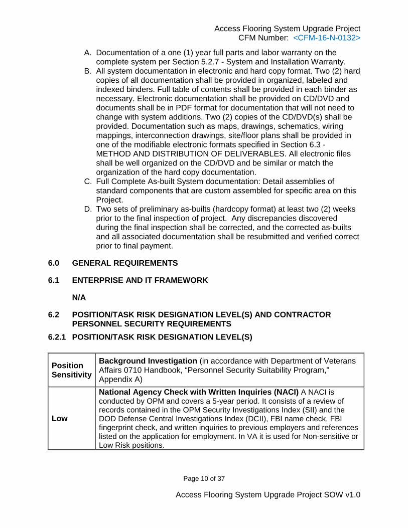
Background Investigation (in accordance with Department of Veterans Affairs 0710 Handbook, “Personnel Security Suitability Program,” Appendix A)
Low
National Agency Check with Written Inquiries (NACI) A NACI is conducted by OPM and covers a 5-year period. It consists of a review of records contained in the OPM Security Investigations Index (SII) and the DOD Defense Central Investigations Index (DCII), FBI name check, FBI fingerprint check, and written inquiries to previous employers and references listed on the application for employment. In VA it is used for Non-sensitive or Low Risk positions.
Access Flooring System Upgrade Project CFM Number: <CFM-16-N-0132>
Page 11 of 37
Access Flooring System Upgrade Project SOW v1.0
Position Sensitivity
Background Investigation (in accordance with Department of Veterans Affairs 0710 Handbook, “Personnel Security Suitability Program,” Appendix A)
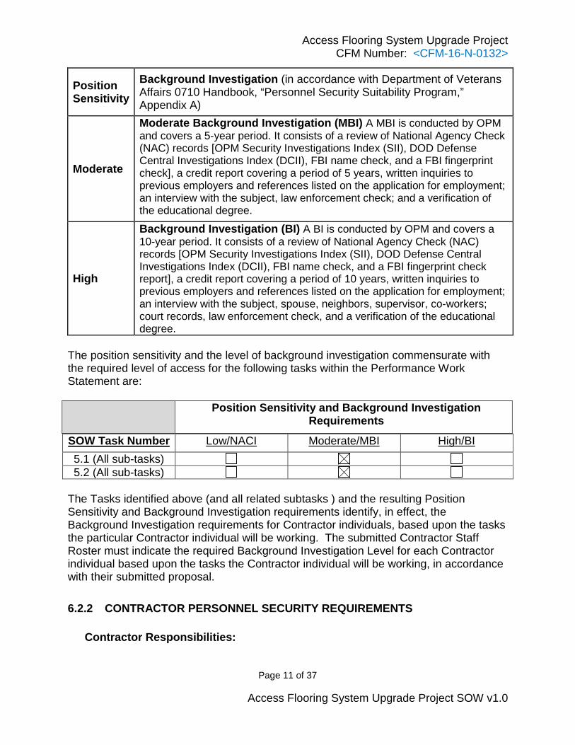
Moderate
Moderate Background Investigation (MBI) A MBI is conducted by OPM and covers a 5-year period. It consists of a review of National Agency Check (NAC) records [OPM Security Investigations Index (SII), DOD Defense Central Investigations Index (DCII), FBI name check, and a FBI fingerprint check], a credit report covering a period of 5 years, written inquiries to previous employers and references listed on the application for employment; an interview with the subject, law enforcement check; and a verification of the educational degree.
High
Background Investigation (BI) A BI is conducted by OPM and covers a 10-year period. It consists of a review of National Agency Check (NAC) records [OPM Security Investigations Index (SII), DOD Defense Central Investigations Index (DCII), FBI name check, and a FBI fingerprint check report], a credit report covering a period of 10 years, written inquiries to previous employers and references listed on the application for employment; an interview with the subject, spouse, neighbors, supervisor, co-workers; court records, law enforcement check, and a verification of the educational degree.
The position sensitivity and the level of background investigation commensurate with the required level of access for the following tasks within the Performance Work Statement are:
Position Sensitivity and Background Investigation Requirements
SOW Task Number Low/NACI Moderate/MBI High/BI 5.1 (All sub-tasks) 5.2 (All sub-tasks)
The Tasks identified above (and all related subtasks ) and the resulting Position Sensitivity and Background Investigation requirements identify, in effect, the Background Investigation requirements for Contractor individuals, based upon the tasks the particular Contractor individual will be working. The submitted Contractor Staff Roster must indicate the required Background Investigation Level for each Contractor individual based upon the tasks the Contractor individual will be working, in accordance with their submitted proposal. 6.2.2 CONTRACTOR PERSONNEL SECURITY REQUIREMENTS
Contractor Responsibilities:
Access Flooring System Upgrade Project CFM Number: <CFM-16-N-0132>
Page 12 of 37
Access Flooring System Upgrade Project SOW v1.0
a. The Contractor shall prescreen all personnel requiring access to the computer systems to ensure they maintain the appropriate Background Investigation, and are able to read, write, speak and understand the English language.
b. The Contractor shall bear the expense of obtaining background investigations.
c. Within 3 business days after award, the Contractor shall provide a roster of Contractor and Subcontractor employees to the COR to begin their background investigations. The roster shall contain the Contractor’s Full Name, Full Social Security Number, Date of Birth, Place of Birth, and individual background investigation level requirement (based upon Section 6.2 Tasks).
d. The Contractor should coordinate the location of the nearest VA fingerprinting office through the COR. Only electronic fingerprints are authorized.
e. For a Low Risk designation the following forms are required to be completed: 1.OF-306 and 2. DVA Memorandum – Electronic Fingerprints. For Moderate or High Risk the following forms are required to be completed: 1. VA Form 0710 and 2. DVA Memorandum – Electronic Fingerprints. These should be submitted to the COR within 5 business days after award.
f. The Contractor personnel will receive an email notification from the Security and Investigation Center (SIC), through the Electronics Questionnaire for Investigations Processes (e-QIP) identifying the website link that includes detailed instructions regarding completion of the investigation documents (SF85, SF85P, or SF 86). The Contractor personnel shall submit all required information related to their background investigations utilizing the Office of Personnel Management’s (OPM) Electronic Questionnaire for Investigations Processing (e-QIP).
g. The Contractor is to certify and release the e-QIP document, print and sign the signature pages, and send them to the COR for electronic submission to the SIC. These should be submitted to the COR within 3 business days of receipt of the e-QIP notification email.
h. The Contractor shall be responsible for the actions of all personnel provided to work for VA under this contract. In the event that damages arise from work performed by Contractor provided personnel, under the auspices of this contract, the Contractor shall be responsible for all resources necessary to remedy the incident.
i. A Contractor may be granted unescorted access to VA facilities and/or access to VA Information Technology resources (network and/or protected data) with a favorably adjudicated Special Agreement Check (SAC) or “Closed, No Issues” (SAC) finger print results, training delineated in VA Handbook 6500.6 (Appendix C, Section 9), and, the signed “Contractor Rules of Behavior.” However, the Contractor will be responsible for the actions of the Contractor personnel they provide to perform work for VA. The investigative history for Contractor personnel working under this contract must be maintained in the database of the Office of Personnel Management (OPM).
Access Flooring System Upgrade Project CFM Number: <CFM-16-N-0132>
Page 13 of 37
Access Flooring System Upgrade Project SOW v1.0
j. The Contractor, when notified of an unfavorably adjudicated background investigation on a Contractor employee as determined by the Government, shall withdraw the employee from consideration in working under the contract.
k. Failure to comply with the Contractor personnel security investigative requirements may result in termination of the contract for default.
l. Any contractor not issued a PIV badge shall be escorted by either a VA employee or a contractor with a PIV badge. PIV badges may not be shared or transferred between employees. The VA shall not provide escorts for the project but if in the course of doing business it is convenient to the government, a VA escort is acceptable.
6.3 METHOD AND DISTRIBUTION OF DELIVERABLES The Contractor shall deliver documentation in full size paper hard copy and in electronic format, unless otherwise directed in Section B of the solicitation/contract. Acceptable electronic media include: MS Word 2000/2003/2007/2010, MS Excel 2000/2003/2007/2010, MS PowerPoint 2000/2003/2007/2010, MS Project 2000/2003/2007/2010, MS Access 2000/2003/2007/2010, MS Visio 2000/2002/2003/2007/2010, AutoCAD 2002/2004/2007/2010/2014, version, and Adobe Postscript Data Format (PDF).
6.4 PERFORMANCE METRICS N/A
6.5 FACILITY/RESOURCE PROVISIONS The Government will provide storage space for materials, tools, equipment and work area space access when authorized contract staff work at a Government location as required in order to accomplish the tasks associated with this SOW. All procedural guides, reference materials, and program documentation for the project and other Government applications will also be provided on an as-needed basis. The Contractor shall request other Government documentation deemed pertinent to the work accomplishment directly from the Government officials with whom the Contractor has contact. The Contractor shall consider the COR as the final source for needed Government documentation when the Contractor fails to secure the documents by other means. The Contractor is expected to use common knowledge and resourcefulness in securing all other reference materials, standard industry publications, and related materials that are pertinent to the work. The Contractor shall not transmit, store or otherwise maintain sensitive data or products in Contractor systems (or media) within the VA firewall IAW VA Handbook 6500.6 dated March 12, 2010. All VA sensitive information shall be protected at all times in accordance with local security field office System Security Plans (SSP’s) and Authority
Access Flooring System Upgrade Project CFM Number: <CFM-16-N-0132>
Page 14 of 37
Access Flooring System Upgrade Project SOW v1.0
to Operate (ATO)’s for all systems/LAN’s accessed while performing the tasks detailed in this PWS. For detailed Security and Privacy Requirements refer to ADDENDUM A and ADDENDUM B.
6.6 GOVERNMENT FURNISHED PROPERTY Listing of Government provided Property/Information (Provided to contractor within 7 calendar days of award): 1. Current computer room flooring system documentation:
a. VA will supply current computer room floor, ramps, steps, installed IT equipment and HVAC equipment drawing of computer room SOW area. VA will provide additional drawing as need to contractor after award.
Access Flooring System Upgrade Project CFM Number: <CFM-16-N-0132>
Page 15 of 37
Access Flooring System Upgrade Project SOW v1.0
ADDENDUM A
A1.0 Cyber and Information Security Requirements for VA IT Services The Contractor shall ensure adequate LAN/Internet, data, information, and system security in accordance with VA standard operating procedures and standard SOW language, conditions, laws, and regulations. The Contractor’s firewall and web server shall meet or exceed VA minimum requirements for security. All VA data shall be protected behind an approved firewall. Any security violations or attempted violations shall be reported to the VA Program Manager and VA Information Security Officer as soon as possible. The Contractor shall follow all applicable VA policies and procedures governing information security, especially those that pertain to certification and accreditation. Contractor supplied equipment, PCs of all types, equipment with hard drives, etc. for contract services must meet all security requirements that apply to Government Furnished Equipment (GFE) and Government Owned Equipment (GOE). Security Requirements include: a) VA Approved Encryption Software must be installed on all laptops or mobile devices before placed into operation, b) Bluetooth equipped devices are prohibited within VA; Bluetooth must be permanently disabled or removed from the device, c) VA approved anti-virus and firewall software, d) Equipment must meet all VA sanitization requirements and procedures before disposal. The COR, CO, the Project Manager, and the Information Security Officer (ISO) must be notified and verify all security requirements have been adhered to. Each documented initiative under this contract incorporates VA Handbook 6500.6, “Contract Security,” March 12, 2010 by reference as though fully set forth therein. The VA Handbook 6500.6, “Contract Security” shall also be included in every related agreement, contract or order. The VA Handbook 6500.6, Appendix C, is included in this document as Addendum B.
Contractor employees shall complete a VA Systems Access Agreement if they are provided access privileges as an authorized user of the computer system of VA.
A2.0 VA Enterprise Architecture Compliance The applications, supplies, and services furnished under this contract must comply with One-VA Enterprise Architecture (EA), available at http://www.ea.oit.va.gov/index.asp in force at the time of issuance of this contract, including the Program Management Plan and VA's rules, standards, and guidelines in the Technical Reference Model/Standards Profile (TRMSP). VA reserves the right to assess contract deliverables for EA compliance prior to acceptance.
A2.1. VA Internet and Intranet Standards:
Access Flooring System Upgrade Project CFM Number: <CFM-16-N-0132>
Page 16 of 37
Access Flooring System Upgrade Project SOW v1.0
A3.0 Notice of the Federal Accessibility Law Affecting All Electronic and Information Technology Procurements (Section 508) On August 7, 1998, Section 508 of the Rehabilitation Act of 1973 was amended to require that when Federal departments or agencies develop, procure, maintain, or use Electronic and Information Technology, that they shall ensure it allows Federal employees with disabilities to have access to and use of information and data that is comparable to the access to and use of information and data by other Federal employees. Section 508 required the Architectural and Transportation Barriers Compliance Board (Access Board) to publish standards setting forth a definition of electronic and information technology and the technical and functional criteria for such technology to comply with Section 508. These standards have been developed are published with an effective date of December 21, 2000. Federal departments and agencies shall develop all Electronic and Information Technology requirements to comply with the standards found in 36 CFR 1194. Section 508 – Electronic and Information Technology (EIT) Standards: The Section 508 standards established by the Architectural and Transportation Barriers Compliance Board (Access Board) are incorporated into, and made part of all VA orders, solicitations and purchase orders developed to procure Electronic and Information Technology (EIT). These standards are found in their entirety at: http://www.section508.gov and http://www.access-board.gov/sec508/standards.htm. A printed copy of the standards will be supplied upon request. The Contractor shall comply with the technical standards as marked:
_x_§ 1194.21 Software applications and operating systems _x_§ 1194.22 Web-based intranet and internet information and applications _x_§ 1194.23 Telecommunications products _x_§ 1194.24 Video and multimedia products _x_§ 1194.25 Self-contained, closed products _x_§ 1194.26 Desktop and portable computers _x_§ 1194.31 Functional Performance Criteria _x_§ 1194.41 Information, Documentation, and Support
The standards do not require the installation of specific accessibility-related software or the attachment of an assistive technology device, but merely require that the EIT be compatible with such software and devices so that it can be made accessible if so required by the agency in the future.
Access Flooring System Upgrade Project CFM Number: <CFM-16-N-0132>
Page 17 of 37
Access Flooring System Upgrade Project SOW v1.0
A4.0 Physical Security & Safety Requirements: The Contractor and their personnel shall follow all VA policies, standard operating procedures, applicable laws and regulations while on VA property. Violations of VA regulations and policies may result in citation and disciplinary measures for persons violating the law.
1. The Contractor and their personnel shall wear visible identification at all times while they are on the premises.
2. It is the responsibility of the Contractor to park in the appropriate designated parking areas. VA will not invalidate or make reimbursement for parking violations of the Contractor under any conditions.
3. Smoking is prohibited inside/outside any building other than the designated smoking areas.
4. Possession of weapons is prohibited. 5. The Contractor shall obtain all necessary licenses and/or permits required to
perform the work, with the exception of software licenses that need to be procured from a Contractor or vendor in accordance with the requirements document. The Contractor shall take all reasonable precautions necessary to protect persons and property from injury or damage during the performance of this contract.
6. Contractor shall comply with VA’s Security Plan that specifies parking personnel access and laydown area.
A5.0 Confidentiality and Non-Disclosure The Contractor shall follow all VA rules and regulations regarding information security to prevent disclosure of sensitive information to unauthorized individuals or organizations. The Contractor may have access to Protected Health Information (PHI) and Electronic Protected Health Information (EPHI) that is subject to protection under the regulations issued by the Department of Health and Human Services, as mandated by the Health Insurance Portability and Accountability Act of 1996 (HIPAA); 45 CFR Parts 160 and 164, Subparts A and E, the Standards for Privacy of Individually Identifiable Health Information (“Privacy Rule”); and 45 CFR Parts 160 and 164, Subparts A and C, the Security Standard (“Security Rule”). Pursuant to the Privacy and Security Rules, the Contractor must agree in writing to certain mandatory provisions regarding the use and disclosure of PHI and EPHI.
1. The Contractor will have access to some privileged and confidential materials of VA. These printed and electronic documents are for internal use only, are not to be copied or released without permission, and remain the sole property of VA. Some of these materials are protected by the Privacy Act of 1974 (revised by PL 93-5791) and Title 38. Unauthorized disclosure of Privacy Act or Title 38 covered materials is a criminal offense.
2. The VA Contracting Officer will be the sole authorized official to release in writing, any data, draft deliverables, final deliverables, or any other written or printed materials pertaining to this contract. The Contractor shall release no
Access Flooring System Upgrade Project CFM Number: <CFM-16-N-0132>
Page 18 of 37
Access Flooring System Upgrade Project SOW v1.0
information. Any request for information relating to this contract presented to the Contractor shall be submitted to the VA Contracting Officer for response.
3. Contractor personnel recognize that in the performance of this effort, Contractor personnel may receive or have access to sensitive information, including information provided on a proprietary basis by carriers, equipment manufacturers and other private or public entities. Contractor personnel agree to safeguard such information and use the information exclusively in the performance of this contract. Contractor shall follow all VA rules and regulations regarding information security to prevent disclosure of sensitive information to unauthorized individuals or organizations as enumerated in this section and elsewhere in this Contract and its subparts and appendices.
4. Contractor shall limit access to the minimum number of personnel necessary for contract performance for all information considered sensitive or proprietary in nature. If the Contractor is uncertain of the sensitivity of any information obtained during the performance this contract, the Contractor has a responsibility to ask the VA Contracting Officer.
5. Contractor shall train all of their employees involved in the performance of this contract on their roles and responsibilities for proper handling and nondisclosure of sensitive VA or proprietary information. Contractor personnel shall not engage in any other action, venture or employment wherein sensitive information shall be used for the profit of any party other than those furnishing the information. The sensitive information transferred, generated, transmitted, or stored herein is for VA benefit and ownership alone.
6. Contractor shall maintain physical security at all facilities housing the activities performed under this contract, including any Contractor facilities according to VA-approved guidelines and directives. The Contractor shall ensure that security procedures are defined and enforced to ensure all personnel who are provided access to patient data must comply with published procedures to protect the privacy and confidentiality of such information as required by VA.
7. Contractor must adhere to the following: a. The use of “thumb drives” or any other medium for transport of
information is expressly prohibited. b. Controlled access to system and security software and
documentation. c. Recording, monitoring, and control of passwords and privileges. d. All terminated personnel are denied physical and electronic access to
all data, program listings, data processing equipment and systems. e. VA, as well as any Contractor (or Subcontractor) systems used to
support development, provide the capability to cancel immediately all access privileges and authorizations upon employee termination.
f. Contractor PM and VA PM are informed within twenty-four (24) hours of any employee termination.
Access Flooring System Upgrade Project CFM Number: <CFM-16-N-0132>
Page 19 of 37
Access Flooring System Upgrade Project SOW v1.0
g. Acquisition sensitive information shall be marked "Acquisition Sensitive" and shall be handled as "For Official Use Only (FOUO)".
h. Contractor does not require access to classified data. 8. Regulatory standard of conduct governs all personnel directly and indirectly
involved in procurements. All personnel engaged in procurement and related activities shall conduct business in a manner above reproach and, except as authorized by statute or regulation, with complete impartiality and with preferential treatment for none. The general rule is to strictly avoid any conflict of interest or even the appearance of a conflict of interest in VA/Contractor relationships.
Access Flooring System Upgrade Project CFM Number: <CFM-16-N-0132>
Page 20 of 37
Access Flooring System Upgrade Project SOW v1.0
ADDENDUM B APPLICABLE PARAGRAPHS TAILORED FROM: THE VA INFORMATION AND INFORMATION SYSTEM SECURITY/PRIVACY LANGUAGE, VA HANDBOOK 6500.6, APPENDIX C, MARCH 12, 2010
GENERAL B1.
Contractors, Contractor personnel, Subcontractors, and Subcontractor personnel shall be subject to the same Federal laws, regulations, standards, and VA Directives and Handbooks as VA and VA personnel regarding information and information system security.
Access Flooring System Upgrade Project CFM Number: <CFM-16-N-0132>
Page 21 of 37
Access Flooring System Upgrade Project SOW v1.0
ADDENDUM C C1. SPECIFICATIONS FOR ACCESS FLOORING SYSTEM
PART 1 - GENERAL 1.1 DESCRIPTION:
A. Access flooring is to consist of a series of modular, removable, interchangeable
panels on an elevated support system forming an accessible underfloor cavity to
accommodate electrical, data, telecommunication and mechanical services.
System is to be gravity-held panels on bolted stringer understructure.
1.2 RELATED WORK: A. Sustainable Design Requirements: Section 01 81 13, SUSTAINABLE DESIGN
REQUIREMENTS.
B. Color and Texture of Finishes: Section 09 06 00, SCHEDULE FOR FINISHES.
C. Connection of access flooring systems to building ground:
Section 26 05 26, GROUNDING AND BONDING FOR ELECTRICAL SYSTEMS
Section 27 05 26, GROUNDING AND BONDING FOR COMMUNICATIONS
SYSTEMS Section 28 05 26, GROUNDING AND BONDING FOR ELECTRONIC
SAFETY AND SECURITY.
D. Electrical distribution components: Refer to applicable construction documents.
1.3 DESIGN CRITERIA: A. Structural Performance per CISCA A/F: Provide access flooring systems capable
of withstanding the following loads and stresses within limits and under
conditions indicated, as determined by testing manufacturer's current standard
products according to referenced procedures in CISCA:
1. Ultimate-Load Performance: Provide access flooring systems capable of
withstanding a minimum ultimate concentrated load equal to value obtained
by multiplying specified concentrated floor panel design load by a factor of
2.5, without failing, according to CISCA A/F, Section II, "Ultimate Loading."
Access Flooring System Upgrade Project CFM Number: <CFM-16-N-0132>
Page 22 of 37
Access Flooring System Upgrade Project SOW v1.0
Failure is defined as the point at which access flooring system will not take
any additional load.
2. Rolling-Load Performance: Provide access flooring systems capable of
withstanding rolling loads of the following magnitude applied to non-
perforated panels, with a combination of local and overall deformation not to
exceed 1.02 mm (0.040 inch) after exposure to rolling load over CISCA A/F
Path A or B, whichever path produces the greatest top-surface deformation,
according to CISCA A/F, Section III, "Rolling Loads."
a. CISCA A/F Wheel 1 Rolling Load: 5338 N (1200 lbf).
b. CISCA A/F Wheel 2 Rolling Load: 4448 N (1000 lbf).
B. Pedestal Assembly:
1. Pedestal Axial-Load Performance: Provide pedestal assemblies, without
panels or other supports in place, capable of withstanding a 40,034 N (9000
lbf) axial load per pedestal, according to CISCA A/F, Section V, "Pedestal
Axial Load Test."
2. Pedestal Overturning-Moment Performance: Provide pedestal assemblies,
without panels or other supports in place, capable of withstanding an
overturning moment per pedestal of 113 N x meters (1000 lbf x inches),
according to CISCA A/F, Section VI, "Pedestal Overturning Moment Test."
3. Provide a means of leveling and locking the assembly at a selected height
which requires deliberate action to change height setting and which prevents
vibrating displacement.
4. Height between the finish floor and underside of panel or stringer can change
based on latest product. Contractor shall maintain new installed finish floor
elevation to existing finish floor elevation.
a. Not less than existing inches.
C. Stringer:
1. Stringer Concentrated-Load Performance: Provide stringers, without panels in
place, capable of withstanding a concentrated load of 2447 N (550 lbf) at
Access Flooring System Upgrade Project CFM Number: <CFM-16-N-0132>
Page 23 of 37
Access Flooring System Upgrade Project SOW v1.0
center of span with a permanent set not to exceed 0.25 mm (0.010 inch), as
determined per CISCA A/F, Section IV, "Stringer Load Testing."
D. Panels:
1. All panels are to be interchangeable except those altered to meet special
conditions.
2. Concentrated-Load Performance: Provide floor panels, including those with
cutouts, capable of withstanding a concentrated design load of the following
magnitude, with a top-surface deflection under load and a permanent set not
to exceed, respectively, 2.03 and 0.25 mm (0.080 inch and 0.010 inch),
according to CISCA A/F, Section I, “Concentrated Loads."
a. 6672 N (1500 lbf).
3. Floor Panel Impact-Load Performance: Provide access flooring system
capable of withstanding an impact load of 778 N (175 lbf) when dropped from
914 mm (36 inches) onto a 6.5-sq. cm (1-sq. in.) area located anywhere on
the panel, without failing. Failure is defined as collapse of access flooring
system.
4. Panel Drop Test: Provide access flooring system with panel capable of
meeting all structural performance requirements specified, after the panel is
dropped from a height of 36” inches onto concrete surface.
E. Installed access floor is to be level within plus or minus 1.59 mm in 3.05 m (1/16
inch in 10 feet), and plus or minus 3.18 mm (1/8 inch) over the entire area. Floor
assembly shall be rigid, free of vibration, rocking panels, rattles and squeaks.
F. Leakage: Air leakage through the joints between panels and around the perimeter
of the floor system not to exceed .057 cubic meters (2 cubic feet) of air per
minute per linear 305 mm (1 foot) of joint subjected to 125 Pa (0.5 inch, water
gage) positive pressure in the plenum.
G. Grounding: Components to be in direct positive contact for safe continuous
electrical grounding of the entire floor system.
1. Panel to Understructure Resistance: Not more than 10 ohms as measured
without floor coverings, according to test method as specified in ASTM F 150
Access Flooring System Upgrade Project CFM Number: <CFM-16-N-0132>
Page 24 of 37
Access Flooring System Upgrade Project SOW v1.0
with 500-V applied voltage with one electrode on the top face of the panel and
one electrode attached to the tube of the pedestal.
H. Static Electricity Control for High Pressure Laminated (HPL) Floor Covering
Properties: The acceptable electrical resistance range is from not less than 0.5
mega ohms minimum to not more than 20,000 mega ohms maximum. Maximum
electrical resistance is to be measured from the top of the panel to the grounded
subfloor. Exposed metal will not be allowed at the wearing surface of the floor.
I. Uniform Load Test: Provide access flooring system capable of withstanding a
uniform load of 450 lbf/ft2 (21,546 N/M2) placed the over area one panel with a
permanent set not to exceed 0.010 “ inch (0.25 mm) after the load is removed,
according to CISCA/AF Section VII, “Uniform Load Test”.
1.4 SUBMITTALS:
A. Submit in accordance with Section 01 33 23, SHOP DRAWINGS, PRODUCT
DATA, AND SAMPLES.
B. Samples: Full sized floor panel and each understructure component.
C. Shop Drawings: Include complete layout of access flooring system based of field
verified dimensions.
1. Floor panel layout, including railing, step and ramp location. Details and
sections with descriptive notes indicating, finishes, fasteners, typical and
special edge condition, accessories and understructure.
2. Detail components of assembly, anchoring methods and edge details,
including cut-out details, method of grounding. Detail cut sheets for each type
of product indicated, including accessories, to show the information
necessary to make a full evaluation of the entire flooring system.
D. Manufacturer’s Literature and Data: Access floor product certificates. For each
type of access flooring system indicated, to certify that the flooring system meets
the requirements of these written specification and signed by a qualified
employee of the manufacture.
E. Manufacturer’s Certificates: Flame spread rating.
Access Flooring System Upgrade Project CFM Number: <CFM-16-N-0132>
Page 25 of 37
Access Flooring System Upgrade Project SOW v1.0
F. Floor System Test Reports: Submit certified test reports, from a testing laboratory
satisfactory to the COR, attesting that the floor system proposed for installation
meets all specified requirements. Submit test reports with shop drawings.
G. Manufacturer’s Qualifications. See Addendum D
H. Installer’s Qualifications. See Addendum D
1.5 QUALITY ASSURANCE:
A. Manufacturer’s Qualifications: Manufacturer with three (3) years’ experience in
providing items of type specified.
B. Installer’s Qualifications: Installers who are trained and approved by manufacturer
and have a minimum of three (3) years’ experience installation of units required
for this project.
C. Obtain access flooring from single manufacturer.
D. Mockup: Build mockup of typical access flooring assembly five (5) floor panels in
length and five (5) floor panels in width. If approved by COR, approved mockups
may become part of the completed work if undisturbed at the time of Substantial
Completion.
1.6 DELIVERY, STORAGE AND HANDLING:
A. Delivery:
1. Deliver materials to site in undamaged condition, in original containers or
packages, complete with accessories and instructions. Label packages with
manufacturer’s name and brand designations. Package materials covered by
specific references bearing specification number, type, and class as
applicable.
B. Storage:
1. Store all materials in original protective packaging in a safe, dry, and clean
location. Store panels at temperatures between 4 and 32 degrees C (40 and
90 degrees F) and between 20 and 70 percent humidity. Replace defective or
damaged materials.
Access Flooring System Upgrade Project CFM Number: <CFM-16-N-0132>
Page 26 of 37
Access Flooring System Upgrade Project SOW v1.0
C. Handling:
1. Handle and protect materials in a manner to prevent damage during the entire
construction period.
1.7 WARRANTY: A. Construction Warranty: Comply with FAR clause 52.246-21, “Warranty of
Construction”.
1.8 APPLICABLE PUBLICATIONS:
A. The publications listed below form a part of this specification to the extent
referenced. The publications are referenced in the text by the basic designation
only.
B. American Association of Textile Chemists and Colorists (AATCC):
134-11 ...............................Electrostatic Propensity of Carpets
C. Architectural Aluminum Manufacturers Association (AAMA):
2604-10 .............................High Performance Organic Coatings on Aluminum
Extrusions and Panels.
D. ASTM International (ASTM):
E84-14 ...............................Surface Burning Characteristics of Building Materials
E648-14c ...........................Critical Radiant Flux of Floor-Covering Systems Using
a Radiant Heat Energy Source
F150-06(R2013) ................Electrical Resistance of Conductive and Static
Resilient Flooring
F1066-04(R2014) ..............Vinyl Composition Floor Tile
F1700-13a .........................Solid Vinyl Floor Tile
E. Code of Federal Regulation (CFR):
40 CFR 59 .........................Determination of Volatile Matter Content, Water
Content, Density Volume Solids, and Weight Solids of
Surface Coating
F. National Association of Architectural Metal Manufacturers (NAAMM):
AMP 500 Series .................Metal Finishes Manual
Access Flooring System Upgrade Project CFM Number: <CFM-16-N-0132>
Page 27 of 37
Access Flooring System Upgrade Project SOW v1.0
G. National Electrical Manufacturers Association (NEMA):
LD-3.1-05 ..........................Application, Fabrication, and Installation of High-
Pressure Decorative Laminates
H. Ceilings and Interior Systems Construction Association (CISCA):
CISCA 2004.......................Recommended Test Procedures for Access Floors
I. National Fire Protection Association (NFPA):
75-13 .................................Fire Protection of Information Technology Equipment
J. Underwriters Laboratory (UL):
94-06(R2014) ....................Tests for Flammability of Plastic Materials for Parts in
Devices and Appliances
PART 2 - PRODUCTS 2.1 FLOOR COVERING:
A. HIGH PRESSURE LAMINATE: Conductive Plastic Laminate: NEMA LD3, High-Wear type, Grade HW-62
fabricated in one (1) piece to cover each panel face within perimeter plastic
edging or with integral trim serving as edging. // Static decay of 5000 to 0 V in
less than 0.5 seconds per FS 101C/4046 at 15 percent relative humidity //.
2.2 FLOOR PANELS:
A. Construct panels to be uniform in face dimensions, within a tolerance of plus or
minus 0.38 mm (0.015 inches) of required size and be square within a tolerance
of plus or minus 0.38 mm (0.015 inches), and flatness within a tolerance of plus
or minus 0.5 mm (0.02 inches). Design individual floor panels to be easily placed
and removed, without disturbing adjacent panels or understructure, by one (1)
person using a tool furnished by the access floor manufacturer. Provide panels
610 by 610 mm (24 by 24 inches) in size.
B. Filled Formed-Steel Panels: Contractor option of panel construction described
below:
1. Particleboard core panels not less than 25 mm (1 inch) thick laminated to top
and bottom face sheets of zinc-coated steel not less than 0.45 mm (0.0179
Access Flooring System Upgrade Project CFM Number: <CFM-16-N-0132>
Page 28 of 37
Access Flooring System Upgrade Project SOW v1.0
inches) thick. Enclose edges of core with upturned, die formed edge of
bottom sheet with perimeter channel welded to top and bottom sheets. The
completed panels will have a flame spread rating of 25 or less when tested in
accordance with ASTM E84.
2. Cementitious-filled panels fabricated with die-cut flat top sheet and die-formed
and stiffened bottom pan formed from cold-rolled steel sheet joined together
by resistance welding to form an enclosed assembly, with metal surfaces
protected against corrosion by manufacturer's standard factory-applied finish.
3. Lightweight concrete filled panels fabricated with flat top sheet and bottom
pan formed from electrolytic-zinc-coated, cold-rolled steel sheet joined
together permanently and structurally by hemming and joined to concrete
core by adhesive to form an enclosed assembly.
E. Provide perimeter of panels with continuous extruded // conductive // vinyl edge
strips. Top edge of strip to be flush with panel floor finish. Mechanically lock edge
strips and fasten in place with adhesive.
F. Perforated Panels: Flat, perforated top surface with holes slots of number,
spacing, and size standard with manufacturer to produce a nominal open area of
25% percent and with a downward airflow with damper of 550 cfm at 0.10 inch
wg static pressure.
2.3 CUT-OUTS: A. Fabricate cut-outs in floor panels to accommodate cable penetrations and
service outlets where shown on construction documents or specified. Provide
reinforcement or additional support to make panels with cut-outs perform the
same as solid uncut panels. Fit cut-outs with manufacturer’s standard grommet.
For cut-outs larger than maximum size grommet, trim edge of cut-outs with
plastic trim, molding and/or gaskets having tapered top flange. Provide
removable twist close covers for grommets.
Access Flooring System Upgrade Project CFM Number: <CFM-16-N-0132>
Page 29 of 37
Access Flooring System Upgrade Project SOW v1.0
1. Provide foam-rubber pads for sealing annular space formed in cutouts by
cables and trim edge of cutout with molding having flange and ledge for
capturing and supporting pads.
2.4 ACCESSORIES: A. Panel Lifting Device: Manufacturer's standard portable lifting device of type
required for lifting panels with floor covering provided. Provide four (4) lifting
devices of each type required. Device shall be located in computer room with
marked sign.
B. Perimeter Support: Where indicated on construction documents, provide
manufacturer's standard method for supporting panel edge and form transition
between access flooring and adjoining floor covering at same level as access
flooring.
C. Floor Cleaner: Type recommended by the floor covering manufacturer.
2.5 PEDESTALS: A. Provide manufacturer's standard pedestal assembly including base, column with
provisions for adjustment, locking device, head and pad.
1. Base: Provide pedestal base with not less than 101 by 101 mm (4 by
4 inches) of bearing area.
2. Column: Hollow shaft of appropriate length fitted with threaded rod and
leveling nut. Welded to base plate and of height required to bring finish floor
to existing finish floor elevation height.
3. Provide vibration proof mechanism for making and holding fine adjustments in
heights for leveling purposes over a range of not less than 50 mm (2 inches).
Include means of locking mechanism at a selected height.
4. Heads: Provide heads designed to accommodate bolted stringers.
5. Pads: Provide sound dampening pad for each pedestal head. Pedestal head
to accept bolted stringers as specified.
Access Flooring System Upgrade Project CFM Number: <CFM-16-N-0132>
Page 30 of 37
Access Flooring System Upgrade Project SOW v1.0
6. Fabricate units of sufficient height to provide required under floor clearance
indicated in construction documents.
2.6 PEDESTAL BASE ADHESIVE: A. Type recommended by manufacturer.
1. Adhesive to have a VOC content of 70 g/L or less when calculated according
to 40 CFR 59, (EPA Method 24).
2.7 STRINGERS: A. Form stringers from extruded aluminum or zinc coated steel in 610 mm (2 foot)
lengths. Attach stringers to pedestals with threaded fasteners accessible from
above. Stringer system to form a grid pattern with members under edges of floor
panels and with pedestals under adjacent panel corners of each floor panel.
Provide stringer that supports each edge of each panel.
2.8 RAMPS AND STEPS: A. Bolt, ramps, and steps to framing. Form step nosing, threshold strip, and floor
bevel strip from extruded or cast aluminum, with non-slip traffic surface. Close
exposed sides of ramp and steps with not thinner than 18 gage aluminum,
reinforced on the back to prevent warp. Install ramp shoes to meet main and
raised access floor.
B. Ramps: Manufacturer's standard ramp construction of width and slope indicated,
but not steeper than 1:12, with manufacturer’s standard non-slip floor finish, and
of same materials, performance, and construction requirements as access
flooring.
C. Steps: Provide steps of size and arrangement indicated on construction
documents with manufacturer’s standard non-slip floor finish and nosings.
Access Flooring System Upgrade Project CFM Number: <CFM-16-N-0132>
Page 31 of 37
Access Flooring System Upgrade Project SOW v1.0
2.9 RAILING AND POSTS:
A. Construct rails and posts from 32 mm (1-1/4 inch) round extruded aluminum tube
shapes. Weld all joints and finish to texture of tubing. Flanges may be welded, or
bolted to rails and supports.
B. Railings: Standard extruded aluminum railings, at ramps and open sided
perimeter of access flooring where indicated on construction documents. Include
handrail, intermediate rails, posts, brackets, end caps, wall returns, wall and floor
flanges, plates, and anchorage where required. Provide railings that comply with
structural performance requirements mandated by code.
2.10 FINISHES:
A. General: Apply finishes in factory after products are fabricated. Protect finishes
on exposed surfaces with protective covering before shipment. Colors, Textures
and Patterns will be approved by COR during product submittal review.
PART 3 - EXECUTION 3.1 PREPARATION:
A. Examine sub-floor for any problems that would prevent a satisfactory installation
of access floor, such as moisture and unevenness of top surface.
B. Install floor sealer, required for dust or vapor control, prior to installation of
pedestals, only if the pedestal adhesive will not damage the coating. If the
coating and adhesive are not compatible, apply the coating after the pedestals
have been installed and the adhesive has cured. Concrete sealer are to be
provided if an under floor mechanical air plenum is being used.
C. Prior to installation, subfloor is to be dry and free of any surface irregularities that
will adversely affect access flooring system appearance or performance.
D. Clear the area in which the floor system is to be installed of debris. Clean floor
surfaces and remove dust before the work is started.
Access Flooring System Upgrade Project CFM Number: <CFM-16-N-0132>
Page 32 of 37
Access Flooring System Upgrade Project SOW v1.0
E. Access to installation area shall be provided by VA-HITC per approved work
phase schedule.
F. Materials storage and installation area: Access floor material area to receive and
store shall be enclosed and dry. Storage area shall be maintained at a
temperature of not less than 40F to 95F degree. Throughout entire duration of
installation work area temperature shall be maintained between 50F to 85F
degree. Relative humidity shall be maintained between 20% to 80% level in
storage and installation area.
3.1.1 Existing Floor Removal/Demolition: A. Perform demolition in such manner as to eliminate hazards to persons and
property; to minimize interference with use of adjacent areas, utilities and
structures or interruption of use of such utilities; and to provide free passage to
and from such adjacent areas of structures.
B. Provide safeguards, including warning signs, barricades, temporary fences,
warning lights, and other similar items that are required for protection of all
personnel during demolition and removal operations.
C. Demolition Work Coordination: Contractor shall survey the site and examine the
drawings and specifications to determine the extent of the work. The contractor
shall take necessary precautions to avoid damages to existing items in place
such as electrical conduits, electrical outlets, mechanical piping, data cable,
operational IT racks, etc. Contractor shall ensure that hanger supports connected
to flooring substructure get disconnected and new independent support installed.
3.2 INSTALLATION: A. Install access floor system and accessories under supervision of the access
flooring manufactures authorized representative to ensure rigid, firm installation
that complies with performance requirements and is free of vibration, rocking,
rattles and squeaks.
Access Flooring System Upgrade Project CFM Number: <CFM-16-N-0132>
Page 33 of 37
Access Flooring System Upgrade Project SOW v1.0
B. Layout floor panel installation to keep the number of cut panels at the floor
perimeter to a minimum and to sizes not less than 1/2 half width to the greatest
extent possible. Scribe panel assemblies at perimeter and around column to
provide a close fit with no voids greater than 6 mm (1/4 inch) where panels abut
vertical surface.
C. Secure bases of pedestals to the structural sub-base with an adhesive
or mechanical fastener in full and firm contact with the subbase using
manufacturers approved method. Set pedestals plumb, and in true alignment.
D. Pedestal location shall be established from approved shop drawings to allow
mechanical and electrical work to be performed without interfering with pedestal
installation.
E. Where pedestal stringer system is used, join the stringers and other framing
members with threaded fasteners for positive connection to the pedestals to
preclude lateral movement. Uniformly space stringers in parallel lines, and place
at the indicated elevation.
F. Provide auxiliary framing around columns and other permanent construction, at
sides of ramps, at free ends of floor, and beneath floor panels that are
substantially cut to accommodate utility systems.
G. Construct floor panels to lie flat without warp or twist and bear uniformly on
supports without rocking, and without edges projecting above the floor plane.
Panels to interlock with supports in a manner that will preclude lateral movement.
H. Provide free ends of floor with positive anchorage and rigid support where floor
system does not abut wall or other construction.
I. Cover exposed ends of floor system with aluminum closures. Closures to consist
of complete trim and fascia assemblies.
J. Pre-mark pedestal location on a grid on sub-floor per approved shop drawing
phase of work so that mechanical and electrical won’t interfere.
Access Flooring System Upgrade Project CFM Number: <CFM-16-N-0132>
Page 34 of 37
Access Flooring System Upgrade Project SOW v1.0
3.3 REPAIR OR WELDED GALVANIZED SURFACES: A. Use galvanized repair compound where galvanized surfaces are scheduled to
receive field or shop coatings, and apply in accordance with manufacturers
printed instructions.
3.4 CLEANING: A. Remove debris accumulated during removal and installation work from beneath
the raised floor system. Immediately after completion of the floor substructure
installation, apply floor cleaner in accordance with the floor covering
manufacturer's instruction. Do not allow any cleaner to remain between individual
panels.
B. On completion of work of this section and after removal of all debris, leave site in
clean condition satisfactory to COR. Clean-up shall include off the VA-HITC
disposal of all items and materials not required to remain property of the
Government as well as all debris and rubbish resulting from demolition
operations.
3.5 PROTECTION: A. Cover cleaned floors with clean building paper before construction traffic is permitted. Remove protective covering at completion of Work.
Access Flooring System Upgrade Project CFM Number: <CFM-16-N-0132>
Page 35 of 37
Access Flooring System Upgrade Project SOW v1.0
ADDENDUM D
D1. Installation Contractor Qualification Requirements D1.1 – Project Manager and/or Lead Technician Qualifications
The Contractor shall submit for approval the name and resume of all employees on their staff who will function as Project Manager and/or Lead Technician for this Project. The project manager’s and/or Lead Technician’s Resume shall indicate at least five projects on which the person worked in the last year, including a point of contact and telephone number of the client (to facilitate verification of satisfactory work experience.) Each Project Manager and/or Lead Technician shall:
1. Be a full-time employee of the installation contractor. 2. Have a minimum of three (3) years' experience in removing and
installing new access flooring and substructure on operational data center computer equipment area, and extent to that indicated for this project, and whose work has resulted in successful in-service performance.
3. Represent the contractor in all matters related to the access flooring system removal and installation.
4. Be responsible for quality assurance, including overseeing all work performed under this SOW, inspecting all materials to be used prior to installation, and inspecting all work after installation.
5. Not be required to be on-site at all times, but shall be accessible by cell phone/pager (with the cell phone number provided to the Contracting Officer and the COR) and shall be required to be present for critical events, such as the final inspection and critical testing events.
D1.2 – Installation Technician Qualifications
The Contractor shall submit for approval the name and resume of all employees on their staff who will function as removal and Installation Technicians for this project. Each Installation Technician's resume shall list at least three projects on which the technician worked in the last year, including a point of contact and telephone number of the client (to facilitate verification of satisfactory work experience). Each Installation Technician shall:
1. Have a minimum of one (1) year experience in removing and installing new access flooring and substructure on operational data center computer equipment area, and extent to that indicated for
Access Flooring System Upgrade Project CFM Number: <CFM-16-N-0132>
Page 36 of 37
Access Flooring System Upgrade Project SOW v1.0
this project, and whose work has resulted in successful in-service performance.
2. Be responsible for quality assurance, inspecting all materials to be used prior to installation and inspecting all work after installation.
Access Flooring System Upgrade Project CFM Number: <CFM-16-N-0132>
Page 37 of 37
Access Flooring System Upgrade Project SOW v1.0
ADDENDUM E
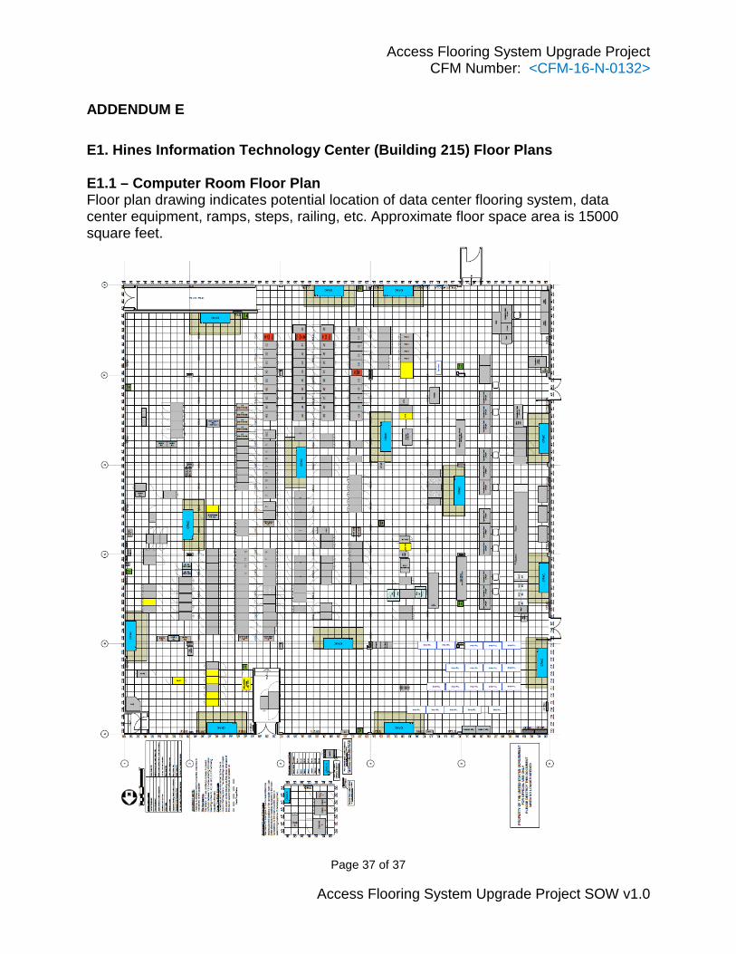
E1. Hines Information Technology Center (Building 215) Floor Plans
E1.1 – Computer Room Floor Plan Floor plan drawing indicates potential location of data center flooring system, data center equipment, ramps, steps, railing, etc. Approximate floor space area is 15000 square feet.