stamping, forming and joining1pp2jy1h0dtm6dg8i11qjfb1-wpengine.netdna-ssl.com/... · 7xxx –for...
TRANSCRIPT

Stamping, Forming and Joining
The Aluminum Transportation Group

2019 Aluminum Transportation Group
Zhi Deng, Ph.D.
Aleris
Global Sr. Applications Engineer
Presenter
2019 Aluminum Transportation Group
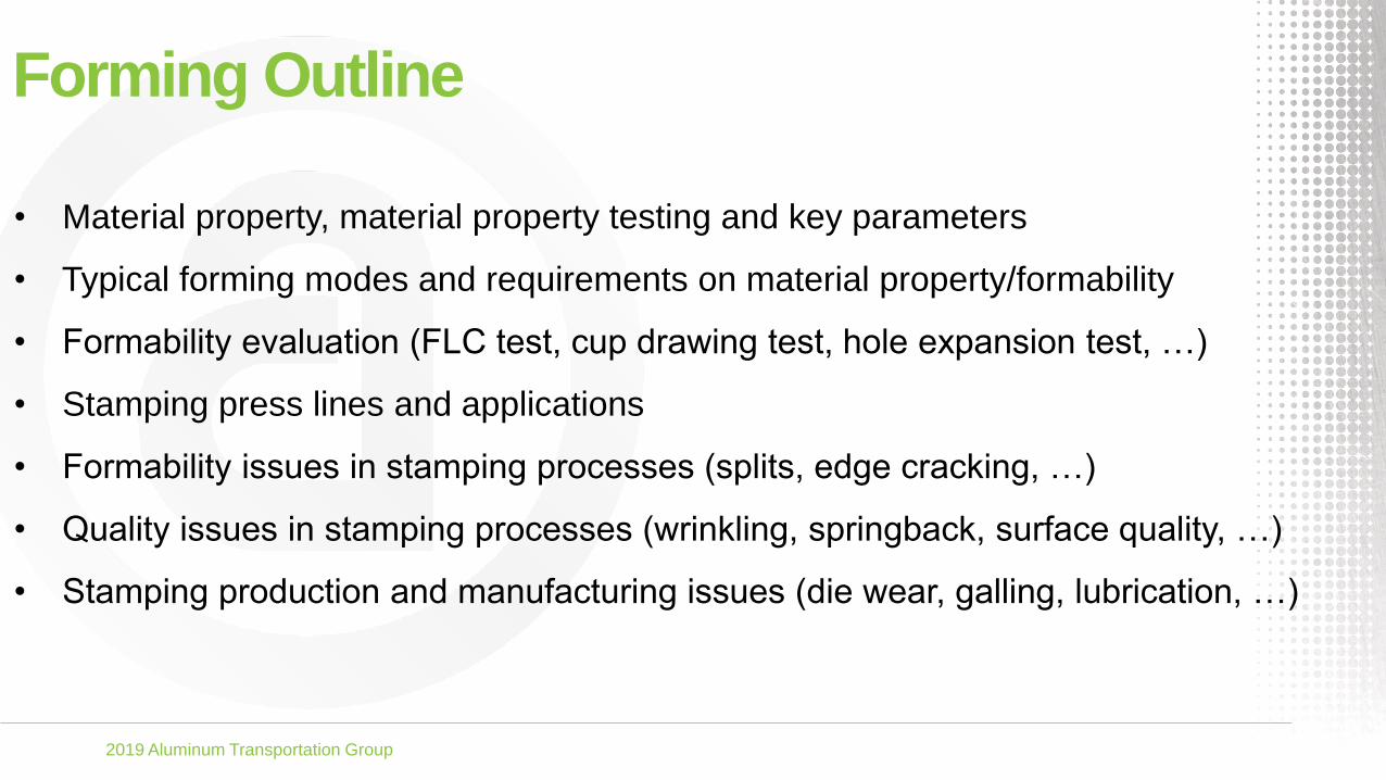
Forming Outline
• Material property, material property testing and key parameters
• Typical forming modes and requirements on material property/formability
• Formability evaluation (FLC test, cup drawing test, hole expansion test, …)
• Stamping press lines and applications
• Formability issues in stamping processes (splits, edge cracking, …)
• Quality issues in stamping processes (wrinkling, springback, surface quality, …)
• Stamping production and manufacturing issues (die wear, galling, lubrication, …)

2019 Aluminum Transportation Group
Development of Automotive Aluminum Alloys 1985~1990 1990~1998 1999~2005 2005~2017
• High formability
• High strength
• High formability
• High bake hardenability
• High formability
• High bake hardenability
• Stretcher strain mark free
(A-Lüderlines)
• High Formability
• High bake hardenability
• High Hemmability
• Dent Resistance
• Natural Aging Control
• Roping free
• Corrosion Resistance
• High-luster paint finish
• Weldability
Surface (Roping)
HemmingHigh Formability
High Strenghts
Crash Pedestrian safety
EDT-Texture Pre-treatment
➢Hot melt
➢Passivation
2019 Aluminum Transportation Group
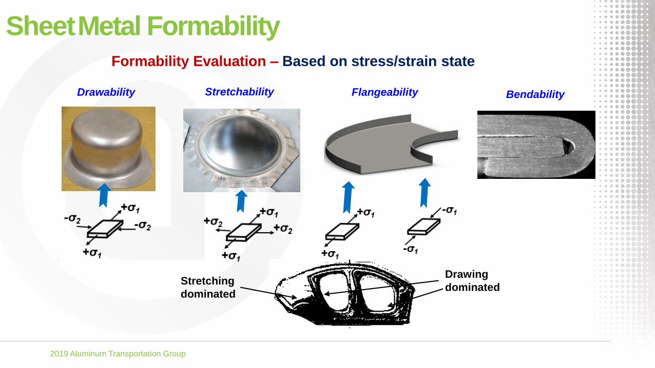
SheetMetal FormabilityFormability Evaluation – Based on stress/strain state
Drawability Stretchability Flangeability Bendability
Drawing
dominatedStretching
dominated

2019 Aluminum Transportation Group
Sheet MetalFormabilityEvaluation
Basic MaterialProperty
Simulative Material
Formability
• Strength
• Elongation
• Strain Hardening
• Anisotropy
• Drawability
• Strechability
• Bendability
• Flangeability
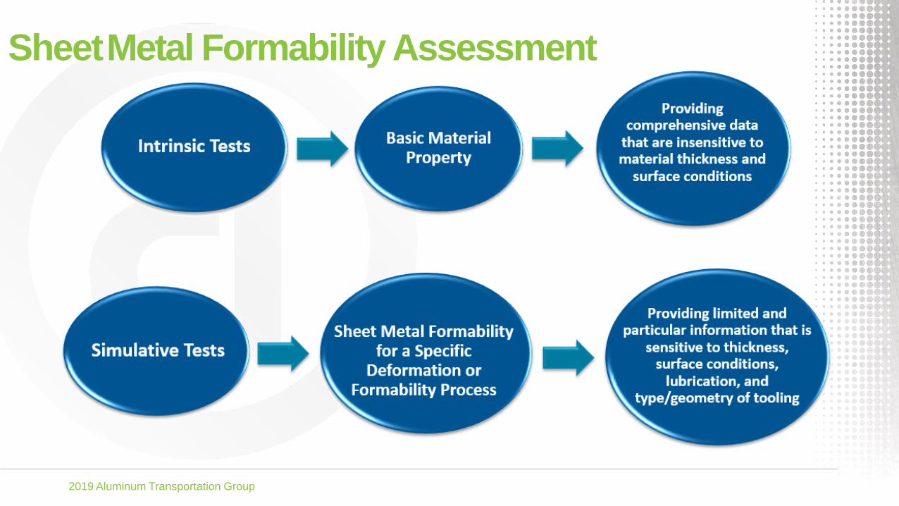
SheetMetal Formability Assessment
2019 Aluminum Transportation Group
SheetMetal Formability Assessment

2019 Aluminum Transportation Group
Basic Material Property Tests
Uniaxial Tensile Test
Hydraulic Bulge Test
Shear Test
Tensile-Compression Test
Buckling Test

2019 Aluminum Transportation Group
Tensile Test vs. BulgeTest
Lock
Bead
YS, TS, UL, TL, n, r
𝑟 =𝜀𝑤
−(𝜀𝑙 + 𝜀𝑤)𝑟𝐵 =
𝜀𝑇𝜀𝑅
Uniaxial
Anisotropy Biaxial
Anisotropy
2019 Aluminum Transportation Group
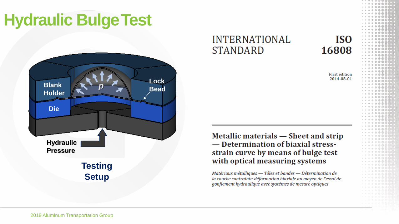
Hydraulic BulgeTest
Testing
Setup
Hydraulic
Pressure
Blank
Holder
Die
Lock
Beadp

2019 Aluminum Transportation Group
Hydraulic BulgeTest
Stress and Strain Calculations
ത𝜎𝑖𝑠𝑜𝑡𝑟𝑜𝑝𝑖𝑐 = 𝑝
2(𝑅𝑏
𝑡+ 1)
ҧ𝜀𝑖𝑠𝑜𝑡𝑟𝑜𝑝𝑖𝑐 = ln 𝑡0
𝑡
ത𝜎𝑎𝑛𝑖𝑠𝑜𝑡𝑟𝑜𝑝𝑖𝑐 = ത𝜎𝑖𝑠𝑜𝑡𝑟𝑜𝑝𝑖𝑐 2 −2𝑟
1+𝑟
ҧ𝜀𝑎𝑛𝑖𝑠𝑜𝑡𝑟𝑜𝑝𝑖𝑐 = 2ത𝜀
𝑖𝑠𝑜𝑡𝑟𝑜𝑝𝑖𝑐
2−2𝑟
1+𝑟

2019 Aluminum Transportation Group
FormingLimitDiagram/ Curve

2019 Aluminum Transportation Group
FLCTest
1
2
3
2 31
Failure
Marginal
, ε
1
, ε2
ε1>0, ε2>0ε1>0, ε2<0 ε1>0, ε2=0
Pla
ne
str
ain
ten
sio
n
Safe

2019 Aluminum Transportation Group
FLC Measurement WithDICDigital Image Correlation (DIC):
• an optical method that employs tracking and image
registration techniques for accurate 2D/3D measurements of
changes in images
• used to measure full-field displacement and strains
• well suited for the characterization of material properties in
the elastic and plastic ranges

2019 Aluminum Transportation Group
FLCTesting Methods
Marciniak Test Nakazima Test
2019 Aluminum Transportation Group
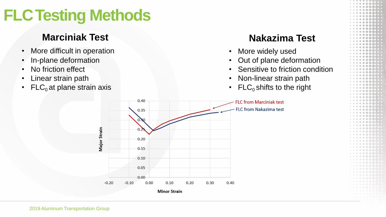
FLCTesting Methods
Marciniak Test
• More difficult in operation
• In-plane deformation
• No friction effect
• Linear strain path
• FLC0 at plane strain axis
• More widely used
• Out of plane deformation
• Sensitive to friction condition
• Non-linear strain path
• FLC0 shifts to the right
Nakazima Test
2019 Aluminum Transportation Group
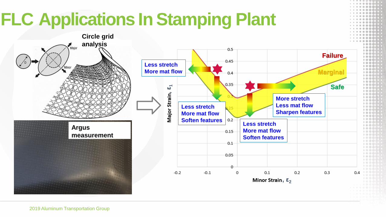
FLC Applications In Stamping PlantCircle grid
analysis
Argus
measurement
Failure
Marginal
Safe
More stretch
Less mat flow
Sharpen features
Less stretch
More mat flow
Soften features
Less stretch
More mat flow
Soften features
Less stretch
More mat flow
, ε
1
, ε2

2019 Aluminum Transportation Group
Simulative FormabilityTests
Specific testing to evaluate sheet metal
Drawability, Stretchability, Flangeability, Bendability
or Combined formability: mostly draw-stretch ability
Other specific testing to evaluate stamping feasibility
Tribology, Surface Quality and Paint Ability

2019 Aluminum Transportation Group
Simulative FormabilityTests–Drawability
Swift Cup Test
Setup
• Most extensively used test to evaluate sheet metal deep drawability
• Circular blanks with progressively larger diameters are clamped between die and blank
holder and deep drawn into cups using a flat-bottomed [50.8 mm (2.0 in.) diameter]
cylindrical punch
• Sheet metal experiences a large deformation in the flange and substantial sliding is
involved at the die radius
2019 Aluminum Transportation Group
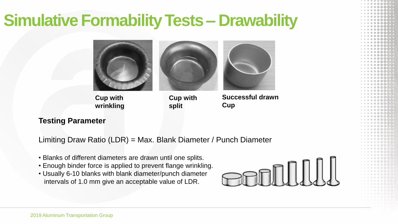
Simulative FormabilityTests–Drawability
Cup with
wrinkling
Cup with
split
Successful drawn
Cup
Testing Parameter
Limiting Draw Ratio (LDR) = Max. Blank Diameter / Punch Diameter
• Blanks of different diameters are drawn until one splits.
• Enough binder force is applied to prevent flange wrinkling.
• Usually 6-10 blanks with blank diameter/punch diameter
intervals of 1.0 mm give an acceptable value of LDR.

2019 Aluminum Transportation Group
Simulative FormabilityTests–Stretchability
Limiting Dome Height (LDH)
Test Setup
• Limiting Dome Height (LDH) test is widely used to
evaluate material stretchability and shows good
repeatability of testing results.
• LDH testing tool can be the same as used for
Nakazima FLC test.
Testing Parameter
LDH Index = Max. Dome Height before Blank Cracking
• In LDH test, specimen is clamped with the lock bead
in order to prevent flange draw in
• LDH testing results correlate better with the total
elongation than with the uniform elongation

2019 Aluminum Transportation Group
Simulative FormabilityTests–Flangeability
Hole Expansion Test Setup
• Specimen with a circular hole in the center
• Clamped between die and blank holder and deformed by a punch
• Expanding and ultimately cracking the edge of the hole
• Flat-bottomed cylindrical and conical punches are mostly used
• Test is terminated when a visible edge crack or fractured hole diameter is
noticed
Testing Parameter
Hole expansion ratio (%) = 𝐷𝑓 −𝐷0
𝐷0
x 100
(D0, Df are the original and final hole diameters.)

2019 Aluminum Transportation Group
Simulative FormabilityTests–BendabilityThree type of bending tests are widely used
• Simple bend test – flat bend over a fixed radius• Wedge bend test – a punch is used to bend the specimen between two rollers• 3-point bend test - a punch is used to bend the specimen between two fixed supports
Simple Bend Test Wedge Bend Test 3-Point Bend Test

2019 Aluminum Transportation Group
Simulative FormabilityTests–Bendability
Hemming Performance Evaluation
Step 1 Step 2

2019 Aluminum Transportation Group
Aluminum Stamping Practices
Cold forming – blanks formed at room temperature
Warm forming – blanks formed at 200~300 0C
Hot forming – blanks formed at 400~500 0C
5xxx – for inner panels only, mostly cold formed, can be warm/hot formed as well
6xxx – for inner panels, mostly cold formed, can be warm/hot formed as well
6xxx – for outer panels, cold formed only
7xxx – for inner structural parts, mostly hot formed, can be cold formed with
W-Temper (T4 temper, solution heat treated, quenching, cold stamping)
Unialloy concept• 6xxx can be used to replace 5xxx for closure inner panels (door/decklid/liftgate)
• Used together with 6xxx closure outer panels,
• No scrap sorting is necessary to optimize resale value of scrap

2019 Aluminum Transportation Group
FromConceptTo Production
Die Design &
EngineeringTryout Production
Concept
Design
Product
Design
Product
Engineering
Production
Planning
Process
Engineering

2019 Aluminum Transportation Group
Aluminum Stamping Press Lines
TransferTandemProgressive
• Typically 5 stand alone press
layout
• For bigger panels (bodyside,
etc.)
• Large investment required
• Higher manufacturing and
maintenance cost
• Low productivity
• Single press with huge bed
• Full die set mounted on press
shoe that moves together
• For mid-size parts (fender, etc.)
• moderate investment required
• Relatively lower manufacturing
and maintenance cost
• Relatively higher productivity
• Single press with huge bed
• Full die set mounted on press
shoe that moves together
• For small-size parts (inner
structural reinforcements, etc.)
• Lower investment required
• Very low manufacturing and
maintenance cost
• Very high productivity

2019 Aluminum Transportation Group
Aluminum StampingProcess
OP 10
Blanking
OP 20
Draw
OP 30
Trim
Cam
Trim
Pierce
OP 40
Trim
Cam
Trim
Pierce
OP 50
Flange
Cam Flange
OP 60
Flange
Cam
Flange
Restrike

2019 Aluminum Transportation Group
Developed Blanks
Monolithic blank Tailor welded blank
• Majority of stamped BIW parts are
made from monolithic blanks
• A developed blank is recommended
when the part formability is a concern
• Together with an optimized drawbead
layout and profiles give precise
control on material flow and
maximize the material formability
potential
• Tailor welded blanks (TWB) are used
for BIW inner panels
• Usually made from sheets with
different thicknesses and material
properties
• It is a good solution for vehicle
lightweighting while maintaining
superior part integrity and functional
performance
2019 Aluminum Transportation Group
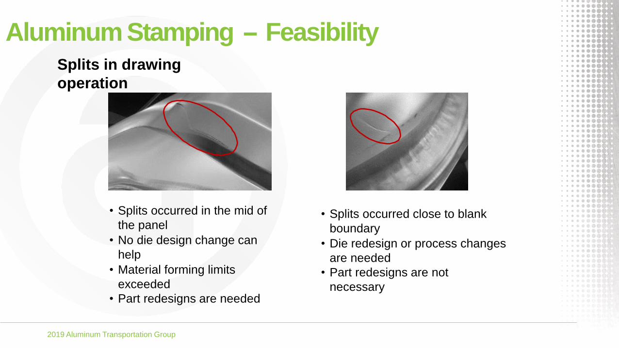
Aluminum Stamping -- FeasibilitySplits in drawing
operation
• Splits occurred in the mid of
the panel
• No die design change can
help
• Material forming limits
exceeded
• Part redesigns are needed
• Splits occurred close to blank
boundary
• Die redesign or process changes
are needed
• Part redesigns are not
necessary
2019 Aluminum Transportation Group
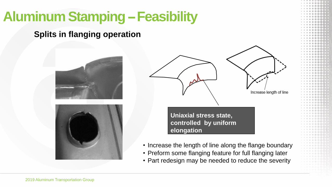
Splits in flanging operation
Aluminum Stamping --Feasibility
Uniaxial stress state,
controlled by uniform
elongation
• Increase the length of line along the flange boundary
• Preform some flanging feature for full flanging later
• Part redesign may be needed to reduce the severity

2019 Aluminum Transportation Group
Edge cracking
Aluminum Stamping --Feasibility
• Caused by cut edge quality of blanks and excessive
stretch along the cut edge
• Tooling effects: clearance, shear angle, cutting
speed, ……
• Laser cut is an alternative to die cutting
2019 Aluminum Transportation Group
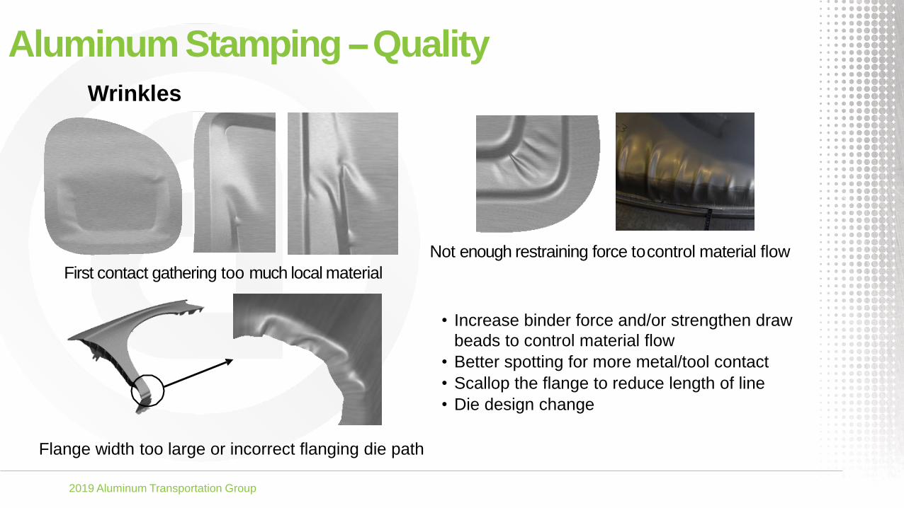
Wrinkles
First contact gathering too much local material
Not enough restraining force tocontrol material flow
Flange width too large or incorrect flanging die path
Aluminum Stamping --Quality
• Increase binder force and/or strengthen draw
beads to control material flow
• Better spotting for more metal/tool contact
• Scallop the flange to reduce length of line
• Die design change

2019 Aluminum Transportation Group
Aluminum Stamping --Quality
Skid line moves beyond the trim line
and show on the class A surface.
Skid line
Trim line
Impact lines shown on the
panel exposed area.
Skid/Impact Lines
Skid/impact lines:
• Surface marks or scratches on
panel exposure areas
• Can be masked during painting
process
• Ideally, conditions which lead to
these lines are resolved during
die design stage

2019 Aluminum Transportation Group
Aluminum Stamping --Quality
Surface low or oil canning caused
by insufficient stretch deformation
Outer Panel Surface Defects
• Change die design – die tip, binder shape,
draw bar to apply extra stretch, …
• Add draw beads, or even double beads
• Increase binder force
• Better spotting for uniform contact and
balanced stretch
Target: Minimum thinning ≥ 2%
2019 Aluminum Transportation Group
Aluminum Stamping --Quality
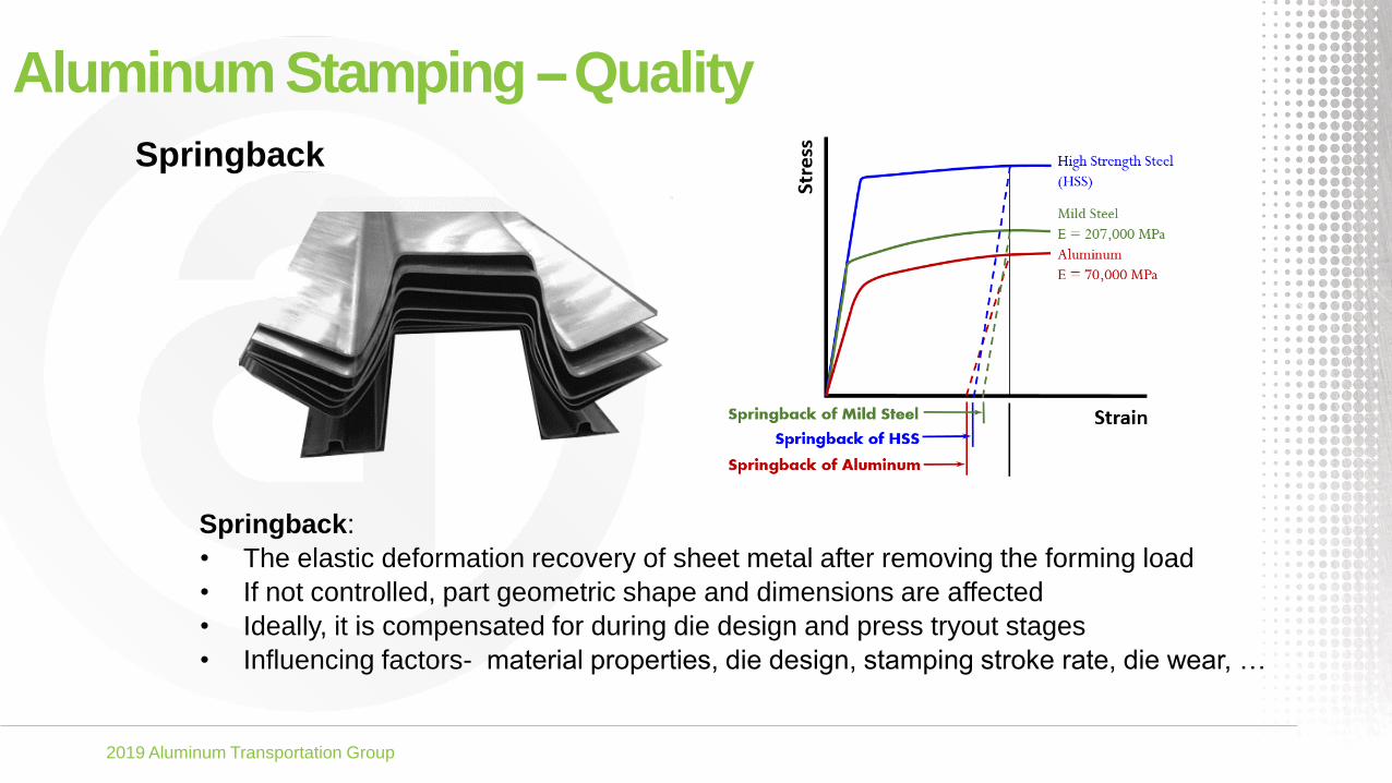
Springback
Springback:
• The elastic deformation recovery of sheet metal after removing the forming load
• If not controlled, part geometric shape and dimensions are affected
• Ideally, it is compensated for during die design and press tryout stages
• Influencing factors- material properties, die design, stamping stroke rate, die wear, …

2019 Aluminum Transportation Group
Aluminum Stamping --Manufacturing• Destacking
• Aluminum is non-magnetic, and needs to be transferred with specific ways such as vacuum
cups and air knife etc.
• Productivity• Associated with die wear, tooling maintenance, ……
• Tooling Maintenance• Aluminum is softer and more easily scratched, affecting surface quality. Good tooling
maintenance schedule and practice are necessary
• Lubrication• Good lubrication practice significantly improves formability, quality and productivity
• Scrap Management• In order to optimize scrap value, 5xxx alloys and 6xxx alloys must be sorted to keep separate

2019 Aluminum Transportation Group
Aluminum Stamping --Manufacturing
Die wear and build-up• Aluminum is softer and is more easily scratched
over small die radii, especially after a certain
number of stamping strokes.
• Severe scratches, in the direction of sliding,
arise from the ploughing of tiny aluminum
particles which are stuck to the die surfaces.
• This leads to die wear and aluminum build-up
on the die surfaces.
• For aluminum stamping, it is necessary to have
a good heat treatment and coatings on die
surfaces.
• Use of Electro Discharge Texturing (EDT)
surface plus dry film lubricant will significantly
improve die wear and build-up.

2019 Aluminum Transportation Group
Aluminum Stamping --Manufacturing
Galling
Galling on panelsurface
Galling:
• Transfer of blank material to surface of the die
• Increases friction which may lead to die
damage if not controlled
• Conditions which lead to galling can be
reduced or prevented by:
• Use of proper lubricants (prelube, dry lube)
• Surface hardening of the tooling
• Polishing die surfaces
• Use of PVD (Physical Vapor Deposition)
coatings
• Conducting regular die maintenance

2019 Aluminum Transportation Group
Aluminum Stamping --Manufacturing
Lubrication• Needed to reduce friction and avoid galling and build up
• Two types of lubrication are widely used
• Mineral oil based -
• more easily applied during blank wash
• is easily removed before painting process
• Dry lubricants -
• are usually applied during coil passivation and heat treatment process
• provide more stable frictional behavior
• good for process stability
• TriboForm Technical Case

2019 Aluminum Transportation Group
Aluminum Stamping --ManufacturingLubrication The friction coefficient is mainly determined by the
lubrication regime.
• full film lubrication case - friction is relatively low.
• boundary lubrication case - entire load is carried by
direct metal-to-metal contact between tool and blank,
friction is much higher.
• In aluminum stamping, the lubrication regime is
somewhere between full film and boundary
lubrication.
Sheet surface finish:
• roughness and waviness can largely change the
lubrication regime.
• EDT finish has a relatively higher roughness, which is
capable of generating micro- pockets containing
lubricant.
• These micro reservoirs may act as a source of extra
lubrication in the process of severe asperity flattening,
and thus shift the lubrication regime closer to full film
lubrication.
Mill Finish EDT Finish
EDT: Electric Discharge Texturing
Multi-Step Frictional Test

2019 Aluminum Transportation Group
Questions?

2019 Aluminum Transportation Group

2019 Aluminum Transportation Group

2019 Aluminum Transportation Group

2019 Aluminum Transportation Group
2019 Aluminum Transportation Group

2019 Aluminum Transportation Group