sta-rite engineering and design manual
TRANSCRIPT

S3430Rev. 9/02
$10.00
Commercial Pool/Spa
Engineering
Design
Manual
Charts and TablesSecond Edition – January 2003

Contents
Pool Design Requirements 1Public Pool Calculations 2
How to Calculate Gallonage 2How to Calculate Radii 2How to Calculate Bathing Load and Displacement of Bathers for Public Pools 3Surge Chamber Design Procedure 4
Diatomaceous Earth Filters 5Basic Principles of Operation 5System..
.3 6
Ultra VAC Vacuum D.E. Rates and Capacities 7Diatomaceous Earth Precoat and Slurry FeedRequirements 8Slurry Feeding and Precoat Dosage Chart 9Slurry Feeding With Diaphragm Feeder Pumps 10
High Rate Sand Filters 11Basic Principles of Operation 12Residential and Commercial Hi-Rate Permanent Media Filters 13Filter Media Requirements Chart for System..
.3
Sand Filters 13S7S50, S8S70, HRPB30 Residential Hi-Rate Permanent Media Filter Rate and Capacity Chart 14Filter Capacity– Vertical Tanks 15Filter Capacity– Horizontal Tanks 15
Modular Media (System...3) for Commercial Applications 16
Head Loss Charts 17Self Priming Pumps 19
CSP/CCSP Commercial Self-Priming Pump 19DH/DM Self-Priming Commercial Pool Pump 19
Type "B" Centrifugal Pumps 20Composite Pump Curves 21Hair and Lint Traps 21
Horizontal Centrifugal Pumps Installation Considerations 22-26Hydraulic Charts and Tables 27
Natural Gas Heater Sizing 27Initial Heat up– BTU Required– 24 Hours 27BTU Required to Maintain Temperature 27Spa Heat Time– 10° Temperature Rise 27Spa Heat Up Time– 30° Temperature Rise 27Formulas 27Heater Efficiencies 27Low Pressure Natural Gas and Propane Gas Pipe Size 28Natural Gas Consumption Meter 28Ventilation Requirements– Indoors 28Centigrade and Fahrenheit Equivalents 28Friction/Flow Chart for Schedule 40 Rigid PVC Pipe 29Friction Loss in Plastic Pipe– Schedule 80 30
Friction/Flow Chart for Standard Steel Pipe 31Flow of Water and Friction Loss per 100 Feet of Type K Copper Tube– 38" to 2" 32Flow of Water and Friction Loss per 100 Feet of Type K Copper Tube– 2-1/2" to 10" Nominal Sizes 33Flow of Water and Friction Loss per 100 Feet of Type L Copper Tube– 3/8" to 2" Nominal Sizes 34Flow of Water and Friction Loss per 100 Feet of Type L Copper Tube– 2-1/2" to 10" Nominal Sizes 35Friction Loss Created By Pipe Fittings 36-37Friction Loss in Pipe Fittings 38-39Mathematics and Calculations 40Steel Pipe Table 41Table for Equalizing Pipes 41Uniform Flow Velocity and Capacity of Sanitary Drains at 1/4" Slope per Foot 42Theoretical Discharge of Nozzles in U.S. Gallons per Minute 42-43Pressure and Equivalent Feet Head of Water 44Feet Head of Water and Equivalent Pressures 44Equivalent Values of Pressure 44Practical Suction Lifts at Various Elevations Above Sea Level 44-45Cavitation 45Net Positive Suction Head 45Approximating Water Flow 46Discharge from Rectangular Weir with End Contractions 47Water Fall and Vanishing Edge Flows 48Vanishing Edge Sump Capacities in Cubic Feet 48Conversion Tables 49Capacity of Square Tanks 50Cylindrical Tanks Set Horizontally and Partially Filled 50Capacity of Round Tanks 51Decimal Equivalents 51Circumferences and Area of Circles 52Viscosity Conversion Tables 53-54Viscosity of Water 54Properties of Water 55
Electrical Usage Charts and Tables 56Power Consumed Pumping 1000 Gallons of Clear Water at One Foot Total Head– Various Efficiencies 56Approximate Cost of Operating Electric Motors 57Single Phase Wire Size Selection Charts 58Three Phase Wire Size Selection Charts 59
Materials 60A Basic Understanding of Plastic Materials Used in Pool and Spa Equipment 60Environmental Factors on Plastics 61Installation of Equipment Made of Plastics 61-64

Pool Design Requirements
1
POOL REQUIREMENTS
The pool designer must first consider the major requirements ofthose using the pool.
1. The population of area to be serviced by swimming facility?
2. The estimated potential bathing load?
3. What percentage of pool use time will be devoted to:
(a) Competitive swimming and training?(To determine the length and minimum width)
(b) Competitive diving and training?(To determine the minimum depths and type of diving equip-ment)
(c) Recreational swimming?(Recreational requirements demand ample shallow area forrelaxed water play)
(d) Swimming instruction and water safety?(The swim coach or pool manager would have definite require-ments governing the instruction area related to the classes tobe taught)
(e) Water polo?(Reflects planning of deep end and width of pool)
(f) Precision swimming (water ballet)?(Area uses for this purpose should be considered in relation tothe spectator positioning)
(g) Skin diving and scuba instruction?(Governing minimum epths for diving area)
TOTAL 100%
A well planned pool will be developed around a combination of two ormore of the above criteria considering them in their position of impor-tance.
POOL SIZE – COMPETITION TYPE POOLS
Definite requirements have been established by NCAA governing theminimum length, width and depth of pools used for swimming compe-tition.
These standards may conflict with the State Health Department regu-lations governing the pool being designed.
A decision must be made applicable to the Health Department andthe purchasing organization with consideration to designing a poolcomplying with requirements for competitive dimensions and afford-ing the maximum safety for the swimmers.
The following excerpts from the NCAA handbook reflect the preferredrequirements to be considered in your preliminary planning: (Seenote, preceding page.)
Long Course Swimming – The racing course should be 164 feet,1.50 in. (50 meters, 2.54 centimeters) in length by 75 feet, 1 inch(22.89m) in width, providing for eight 9-foot (2.74m) lanes with addi-tional width outside lanes 1 and 8. A minimum water depth of 7 feet(2.13m) is desirable for competition. Optional markings: nine 8-foot(2.44m) lanes or ten 7-foot (2.13m) lanes.
Short Course Swimming – The racing course should be 75 feet, 1inch (22.89m) in length by at least 60 feet (18.29m) in width, provid-ing for not less that eight 7-foot (2.13m) lanes with additional widthoutside lanes 1 and 8. A minimum water depth of 7 feet (2.13m) isdesirable for competition.
POOL SIZE – RECREATIONAL TYPE POOLS
Refer to National Spa and Pool Institute for guidelines in planningrecreational type pools.
POOL SHAPES
The standard rectangle used for most competitive type swimmingpools can be deviated from without changing its functional use byemploying an Ell or Tee area, isolating the diving depths from the nor-mal racing field. These combination pools can be designed to incor-porate two different racing lengths.
When an appendage such as this is employed, the pool slopesshould be laid out in the preliminary drawings to assure that therequirements for clearance from the deep end of the pool to the safe-ty rope will allow adequate recreational area. Many State Healthcodes make the installation of an Ell or Tee shaped pool an impracti-cal type of construction for parks and swim clubs where open swim-ming comprises a large quantity of their pools use time.
In pools not governed by competition requirements, those designedfor recreation only, shapes are in no way a governing factor, and theultimate design of the pool could be purely related to the architect’sconcept of what would be attractive to the property, taking into con-sideration the demand for pool safety and adequate supervisionwhere lifeguards are to be employed.
Pool Design Requirements
Public Pool Calculations
2
LIFE GUARD CHAIRS
Life guard chairs must be installed allowing for the maximum cover-age for supervision of both pool and deck.
MISCELLANEOUS EQUIPMENT REQUIRED
Provide cup anchors for facing lanes and safety ropes.
Racing lanes should be construted with continuous floats andequipped with tension adjusting devices.
Provide backstroke and false start indicator posts.
Depth markers should be installed on pool face, and distance mark-ers incorporated into the deck including 220 and 440 yards, 200, 400and 1500 meters.
Where water polo is to be played, goals should be provided withanchors in deck and markings indicating field of play.
Ample underwater and overhead lighting must be installed to complywith State and competition requirements.
Underwater observation areas equipped with an underwater speakersystem affords advantages to the swimming and diving instructor.This underwater speaker system can also be used to supply musicfor synchronized swimming.
Starting blocks must be of an approved design and incorporated aspart of the pool plan as anchors are required for their installation.
DECK AREA
Deck area considerations should include sufficient room for specta-tors, recreational sun bathing and dry swimming instruction.
Areas need to be provided for mechanical equipment installation,showers, change rooms and toilet facilities.
Provide drinking fountains in the pool deck area.
SPECIAL PURPOSE POOLS
Requirements may demand the planning of a special purpose poolincorporated with the designs for a large competitive swimming pool.Special purpose pools in this category would be wading pools, begin-ning swimming instruction pools and hydrotherapy pools. In mostcases, these pools should operate independent of the main swim-ming pool.
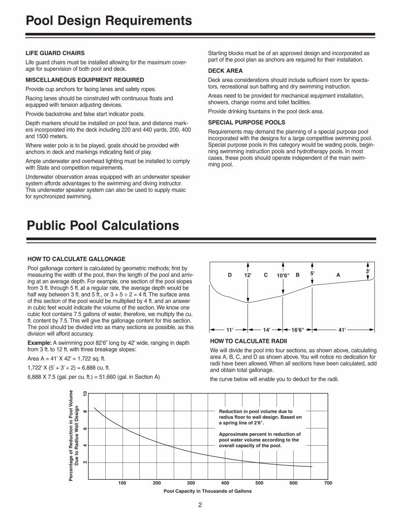
HOW TO CALCULATE GALLONAGE
Pool gallonage content is calculated by geometric methods; first bymeasuring the width of the pool, then the length of the pool and arriv-ing at an average depth. For example, one section of the pool slopesfrom 3 ft. through 5 ft. at a regular rate, the average depth would behalf way between 3 ft. and 5 ft., or 3 + 5 ÷ 2 = 4 ft. The surface areaof this section of the pool would be multiplied by 4 ft. and an answerin cubic feet would indicate the volume of the section. We know onecubic foot contains 7.5 gallons of water, therefore, we multiply the cu.ft. content by 7.5. This will give the gallonage content for this section.The pool should be divided into as many sections as possible, as thisdivision will afford accuracy.
Example: A swimming pool 82’6” long by 42’ wide, ranging in depthfrom 3 ft. to 12 ft. with three breakage slopes:
Area A = 41’ X 42’ = 1,722 sq. ft.
1,722’ X (5’ + 3’ ÷ 2) = 6,888 cu. ft.
6,888 X 7.5 (gal. per cu. ft.) = 51,660 (gal. in Section A)
HOW TO CALCULATE RADII
We will divide the pool into four sections, as shown above, calculatingarea A, B, C, and D as shown above.You will notice no dedication forradii have been allowed. When all sections have been calculated, addand obtain total gallonage.
the curve below will enable you to deduct for the radii.
100 200 300 400 500 600 700
24
68
10
Pool Capacity in Thousands of Gallons
Per
cen
tag
e o
f R
edu
ctio
n in
Po
ol V
olu
me
Du
e to
Rad
ius
Wal
l Des
ign
Reduction in pool volume due toradius floor to wall design. Based ona spring line of 2'6".
Approximate percent in reduction ofpool water volume according to theoverall capacity of the pool.
D C B A10'6" 5' 3'12'
11' 14' 16'6" 41'

Public Pool Calculations
3
HOW TO CALCULATE MAXIMUM BATHING LOAD AND DISPLACEMENT OF BATHERS FOR PUBLIC POOLS
Bathing Load
One bather per 15 square feet of surface area (less than 5 feet deep).
One bather per 20 square feet of surface area (more than 5 feet deep).
Subtract 300 square feet from total square feet of area for each divingboard.
Example
1. Calculate surface square feet of area less than 5 feet deep.
2. Divide this figure by 15 for total number of swimmers.
3. Calculate surface square feet of area more than 5 feet deep.
4. Divide this by 20 for total number of swimmers.
5. Add results of No. 2 and No. 4.
6. Subtract 15 swimmers for each diving board.
7. The remainder is the total number of swimmers for that size pool.
Displacement of Bathers
8. Multiply the results of No. 2 by .75 (assuming the bathers in theshallow water are 75% submerged) and then by 2 (approximatedisplacement in cubic feet per bather).
9. Multiply the results of No. 4 by .9 (bathers in deep water 90%submerged) and then by 2.
10. Add results of No. 8 and No. 9 to give total bather displacementin cubic feet of water.
Bathing Load 100 150 200 250 300 350 400 450 500 550 600 650 700 750 800
Displacement (Gal.) 1500 2250 3000 3750 4500 5250 6000 6750 7500 8250 9000 9750 10500 11250 12000
Main Gutter (gpm) 150 225 300 375 450 525 600 675 750 825 900 975 1050 1125 1200
A – Chamber Length 8’ 8’ 8’ 10’ 10’ 12’ 12’ 14’ 15’ 16’ 18’ 20’ 20’ 20’ 20’
B – Chamber Width 6’ 7’ 8’ 8’ 10’ 10’ 10’ 10’ 10’ 10’ 10’ 10’ 10’ 10’ 10’
C – Chamber Depth 9’6” 11’0” 11’6” 11’6” 11’6” 11’6” 12’0” 12’0” 12’0” 12’6” 12’0” 12’0” 12’6” 13’6” 13’6”
D – C.W. Makeup (IPS) 11⁄2” 11⁄2” 2” 2” 2” 21⁄2” 21⁄2” 21⁄2” 3” 3” 3” 3” 3” 3” 3”
E – Overflow 4” 4” 6” 6” 6” 6” 6” 6” 6” 8” 8” 8” 8” 8” 8”
SURGE CHAMBER SIZING
TYPICAL SURGE CAMBER INSTALLATION
Public Pool Calculations
4
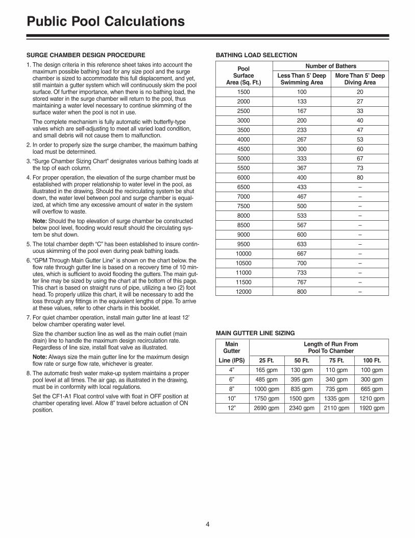
SURGE CHAMBER DESIGN PROCEDURE
1. The design criteria in this reference sheet takes into account themaximum possible bathing load for any size pool and the surgechamber is sized to accommodate this full displacement, and yet,still maintain a gutter system which will continuously skim the poolsurface. Of further importance, when there is no bathing load, thestored water in the surge chamber will return to the pool, thusmaintaining a water level necessary to continue skimming of thesurface water when the pool is not in use.
The complete mechanism is fully automatic with butterfly-typevalves which are self-adjusting to meet all varied load condition,and small debris will not cause them to malfunction.
2. In order to properly size the surge chamber, the maximum bathingload must be determined.
3. “Surge Chamber Sizing Chart” designates various bathing loads atthe top of each column.
4. For proper operation, the elevation of the surge chamber must beestablished with proper relationship to water level in the pool, asillustrated in the drawing. Should the recirculating system be shutdown, the water level between pool and surge chamber is equal-ized, at which time any excessive amount of water in the systemwill overflow to waste.
Note: Should the top elevation of surge chamber be constructedbelow pool level, flooding would result should the circulating sys-tem be shut down.
5. The total chamber depth “C” has been established to insure contin-uous skimming of the pool even during peak bathing loads.
6. “GPM Through Main Gutter Line” is shown on the chart below. theflow rate through gutter line is based on a recovery time of 10 min-utes, which is sufficient to avoid flooding the gutters. The main gut-ter line may be sized by using the chart at the bottom of this page.This chart is based on straight runs of pipe, utilizing a two (2) foothead. To properly utilize this chart, it will be necessary to add theloss through any fittings in the equivalent lengths of pipe. To arriveat these values, refer to other charts in this booklet.
7. For quiet chamber operation, install main gutter line at least 12’below chamber operating water level.
Size the chamber suction line as well as the main outlet (maindrain) line to handle the maximum design recirculation rate.Regardless of line size, install float valve as illustrated.
Note: Always size the main gutter line for the maximum designflow rate or surge flow rate, whichever is greater.
8. The automatic fresh water make-up system maintains a properpool level at all times. The air gap, as illustrated in the drawing,must be in conformity with local regulations.
Set the CF1-A1 Float control valve with float in OFF position atchamber operating level. Allow 8” travel before actuation of ONposition.
Main Length of Run FromGutter Pool To Chamber
Line (IPS) 25 Ft. 50 Ft. 75 Ft. 100 Ft.
4” 165 gpm 130 gpm 110 gpm 100 gpm
6” 485 gpm 395 gpm 340 gpm 300 gpm
8” 1000 gpm 835 gpm 735 gpm 665 gpm
10” 1750 gpm 1500 gpm 1335 gpm 1210 gpm
12” 2690 gpm 2340 gpm 2110 gpm 1920 gpm
MAIN GUTTER LINE SIZING
Pool Number of Bathers
Surface Less Than 5’ Deep More Than 5’ DeepArea (Sq. Ft.) Swimming Area Diving Area
1500 100 20
2000 133 27
2500 167 33
3000 200 40
3500 233 47
4000 267 53
4500 300 60
5000 333 67
5500 367 73
6000 400 80
6500 433 –
7000 467 –
7500 500 –
8000 533 –
8500 567 –
9000 600 –
9500 633 –
10000 667 –
10500 700 –
11000 733 –
11500 767 –
12000 800 –
BATHING LOAD SELECTION

Diatomaceous Earth Filters
5
BASIC PRINCIPLES OF OPERATION
MODEL DEP VERTICAL D.E. FILTERLiquid Flow Path During Filter and Backwash Cycles
Manual System with (Unitrol) Slide Vavle
FILTER CYCLEIn the filter cycle the flow direction is “IN” through the bottom port.Precoat, filter aid is applied to the outside of the element. Thefluid flows from the outside to the inside of each element. Byreversing the flow direction backwash is achieved.
0
51
015
2025 30
3
5
40
45
50
5560
Effluent
Influent(Supply)
HandleDown
3500 0899 0
51
015
2025 30
3
5
40
45
50
5560
Effluent
Influent(Supply)
HandleDown
3500 0899
BACKWASH CYCLE

Diatomaceous Earth Filters
6
No. Filter Flow Rate Turnover Rate
Model of Area 1.5 2.0 6 8No. Units Sq. Ft. GPM GPM Hours Hours
PLD70 1 3654 – 19,440 25,920
– 72 25,920 34,560
S7MD60 1 6090 – 32,400 43,200
– 120 43,200 57,600
S7MD72 1 72108 – 38,880 51,840
– 144 51,840 69,120
1 83125 – 45,000 60,000
– 166 59,760 79,680
2 166249 – 89,640 119,520
– 332 119,520 159,360
3 249373.5 – 143,280 179,280
– 498 179,280 239,040
4 332498 – 179,280 239,040
DEPB83– 664 239,040 318,720
5 415622.5 – 224,100 298,800
– 830 298,800 398,400
6 498747 – 268,920 358,560
– 996 358,560 478,080
7 581871.5 – 313,740 418,320
– 1162 418,320 557,760
8 664996 – 358,560 478,080
– 1328 478,080 637,440
STA-RITE
Note: Recommended flow rate – 1.5 GPM per sq. ft. of filter area.
System 3Model S7MD60 and Model S7MD72
DEPB

Diatomaceous Earth Filters
7
U-V 6 Hour Turnover 8 Hour Turnover
Part No. Model Area 1 GPM Rate 1.5 GPM Rate 1.0 GPM 1.5 GPM 1.0 GPM 1.5 GPM
29830-0056 56 56 56 84 20,160 30,240 26,880 40,320
29830-0066 66 66 66 99 23,760 35,640 31,680 47,520
29830-0112 112 112 112 168 40,320 60,480 53,760 80,640
29830-0132 132 132 132 198 47,520 71,280 63,360 95,040
29830-0224 224 224 224 336 80,640 120,960 107,520 161,280
29830-0264 264 264 264 396 95,040 142,560 126,720 190,080
29830-0336 336 336 336 504 120,960 181,440 161,280 241,920
29830-0396 396 396 396 594 142,560 213,840 190,080 285,120
29830-0448 448 448 448 672 161,280 241,920 215,040 322,560
29830-0528 528 528 528 792 190,080 285,120 253,440 380,160
29830-0560 560 560 560 840 201,600 302,400 268,800 403,200
29830-0660 660 660 660 990 237,600 356,400 316,800 475,200
29830-0672 672 672 672 1008 241,920 362,880 322,560 483,840
29830-0792 792 792 792 1188 285,120 427,680 380,160 570,240
29830-0896 896 896 896 1344 322,560 483,840 430,080 645,120
29830-0924 924 924 924 1386 332,640 498,960 443,520 665,280
29830-1056 1056 1056 1056 1584 380,160 570,240 506,880 760,320
29830-1188 1188 1188 1188 1782 427,680 641,520 570,240 855,360
29830-1320 1320 1320 1320 1980 475,200 712,800 633,600 950,400
29830-1452 1452 1452 1452 2178 522,720 784,080 696,960 1,045,440
29830-1584 1584 1584 1584 2376 570,240 855,360 760,320 1,140,480
ULTRA-VAC™ VACUUM D.E. RATES AND CAPACITIES

Diatomaceous Earth Filters
8
DIATOMACEOUS EARTH PRECOAT AND SLURRY FEEDREQUIREMENTS
Diatomaceous earth filters divided into two basic classifications; pres-sure and vacuum type filters.
Flow rates vary depending upon the type of service, the anticipatedloading and whether or not slurry feeding is to be included. For resi-dential pools flow rates of between 2 and 2-1/2 gallons per minuteper sq. ft. of filter area are obtainable.
Pressure type filters used on other than private pools operate at 2gallon per minute flow rates, except where slurry feeding is used inwhich case to flow may be as high as 2-1/2 gallons per minute persq. ft.
Vacuum type diatomite filters operate at a rate of 1-1/2 to 2 gpm persq. ft. without slurry feed. Total flow is generally calculated on thebasis of an 8 to 12 hour turnover for private pools and 6 to 8 hourturnover for public pools.
PRECOAT, VACUUM AND PRESSURE TYPE
The vacuum precoat vessel is plumbed to the suction side of the circulating pump. The precoat is drawn from the precoat pot undervacuum and introduced into the filter vessel under pressure (seeFigure 4).
The pressure precoat vessel is plumbed between the circulatingpump and the filter system. Fluid, under high pressure, is introducedinto the top of the vessel and leaves through the connection locatedin the bottom of the vessel. The precoat is introduced directly into thefilter face piping (see Figure 5).
Precoating with slurry tank, fill tank 1/4 full with fresh water and addthe required amount of diatomaceous earth into the tank. Start agita-tor. Place filter into operation. Open the gate valve on the city watersupply line connected to the injector. The solution will be drawn fromthe tank by the injector. When the tank is empty shut off the city waterline, precoat is now complete (see Figure 6, Page 9).
Note: 1. The H-B/F must not be operated without a precoat.
2. Precoat must be prepared prior to starting circulating pump,as precoating must take place when the pump is started.
The precoat operation commences on the start of each filter cycle.The precoat is introduced by either a pressure or vacuum type pre-coat vessel.
The amount of precoat is determined by the total square footage ofthe filter unit. An example follows:
A filter containing 100 square feet of filter area, and not utilizing aslurry feeder, requries 15 pounds of D.E. per square foot of filterarea, on the precoat charge.
Formula: 100 sq. ft. X .15 lbs. D.E. = 15 lbs. total precoat charge.
When feeding slurry, the amount per square foot of filter area is .1lbs. per square foot of filter area on precoat charge.
VACUUM TYPE PRECOAT TANKS
PRESSURE TYPE PRECOAT TANKS
Figure 4
Figure 5
Diatomaceous Earth Filters
9
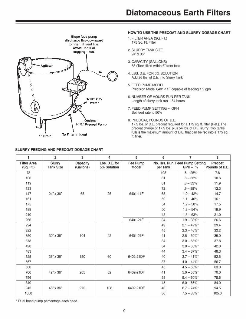
HOW TO USE THE PRECOAT AND SLURRY DOSAGE CHART
1. FILTER AREA (SQ. FT.)175 Sq. Ft. Filter
2. SLURRY TANK SIZE24” x 36”
3. CAPACITY (GALLONS)65 (Tank filled within 6” from top)
4. LBS. D.E. FOR 5% SOLUTIONAdd 26 lbs. of D.E. into Slurry Tank
5. FEED PUMP MODELPrecision Model 6401-11F capable of feeding 1.2 gph
6. NUMBER OF HOURS RUN PER TANKLength of slurry tank run – 54 hours
7. FEED PUMP SETTING – GPHSet feed rate to 50%
8. PRECOAT, POUNDS OF D.E.17.5 lbs. of D.E. precoat required for a 175 sq. ft. filter (Ref.). Theprecoat charge of 17.5 lbs. plus 54 lbs. of D.E. slurry (two tanksfull) is the maximum amount of D.E. that can be fed into a 175 sq.ft. filter.
1 2 3 4 5 6 7 8
Filter Area Slurry Capacity Lbs. D.E. for Fee Pump No. Hrs. Run Feed Pump Setting Precoat(Sq. Ft.) Tank Size (Gallons) 5% Solution Model per Tank GPH – % Pounds of D.E.
78 108 .6 – 25% 7.8106 81 .8 – 33% 10.6119 81 .8 – 33% 11.9133 72 .9 – 38% 13.3147 24” x 36” 65 26 6401-11F 65 1.0 – 42% 14.7161 59 1.1 – 46% 16.1175 54 1.2 – 50% 17.5189 50 1.3 – 54% 18.9210 43 1.5 – 63% 21.0266 6401-21F 34 1.9 – 38%* 26.6294 49 2.1 – 42%* 29.4322 45 2.3 – 46%* 32.2350 30” x 36” 104 42 6401-21F 41 2.5 – 50%* 35.0378 34 3.0 – 63%* 37.8420 34 3.0 – 63%* 42.0483 44 3.4 – 37%* 48.3525 36” x 36” 150 60 6402-21DF 40 3.7 – 41%* 52.5567 37 4.0 – 44%* 56.7630 45 4.5 – 50%* 63.0700 42” x 36” 205 82 6402-21DF 41 5.0 – 55%* 70.0756 38 5.4 – 60%* 75.6840 45 6.0 – 66%* 84.0945 48” x 36” 272 108 6402-21DF 40 6.7 – 74%* 94.51050 36 7.5 – 83%* 105.0
SLURRY FEEDING AND PRECOAT DOSAGE CHART
* Dual head pump percentage each head.
Diatomaceous Earth Filters
10
SLURRY FEEDING WITH DIAPHRAGM FEEDER PUMPS
A feeder pump is provided for the accurate feeding of D.E., slur-ry and water, in conjunction with filtration equipment. The prima-ry use will be for continuous feeding of D.E. (slurry).The process,if done properly, will greatly increase the operating efficiency ofthe filter plant.
The maximum density the feeder pump is designed to handle is5% solution by weight. (Water weighs approximately 8.33pounds per gallon – D.E. weighs approximately 9 pounds percubic foot).
Example: For 50 gallons of “make-up” water, add 20 pounds of D.E.for the maximum density of slurry mixture.
Formula: Capacity of vessel (gallons X 8.33 pounds = total weight x5% = amount of D.E.)
The amount of feed can be determined by the turbidity of thewater. The ideal balance would be 50% – 50% turbidity in partsper million as to slurry in ppm. For example, the average turbidi-ty of a swimming pool runs about 3 ppm.
Formula: Total pool gallons X 8.33 (weight of one gallon) X .000001X ppm = amount of a slurry feed charge.
Example: 240,000 gallons X 8.33 lbs. = 2,000,000 lbs.2,000,000 lbs. X .000001 = 2 lbs. = 1 ppm2 lbs. X 3 ppm = 6 lbs. of D.E. to be fed with every 240,000 gallonsto be filtered.
FEED RATE ADJUSTMENT:
Example: Using Precision Slurry Feeder
The rate of flow on the feeder pump is specified in percents of totalcapacity based on a 24 hour run. the capacity of the Precision No.601 slurry pump is 60 gallons per 24 hours when the pump is set at100%. In the event it were set at 50%, 30 gpd would be the quantityof gallons pumped.
Based on the 100% pumping rate (60 gpd) 24.9 pounds of filter aidwill be delivered every 24 hours.
Example: 60 gpd X 8.33 = 499.8 lbs. of water499.8 X 5% = 24.9 lbs. of filter aid
Or: 30 gallons X 8.33 = 249.9 lbs. water249.9 lbs. X 5” = 12.5 lbs. of filter aid
A typical commercial system may operate at 390 gallons per minute.During a 24 hour period, basing the turbidity of unfiltered water 3ppm, you will be feeding 14 lbs. of filter aid per 24 hours; therefore,your pump should be set at approximately 54%.
With increased bathing load, thus increasing turbidity, naturally therate of feed should be increased. The filter plant operator can experi-ment on the most desirable rate of feed for a particular situation.
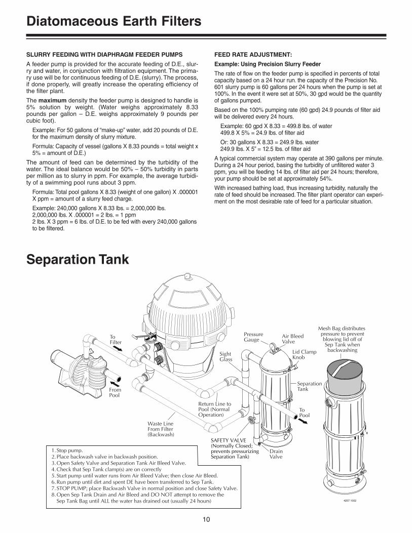
SAFETY VALVE(Normally Closed;prevents pressurizingSeparation Tank)
Mesh Bag distributes pressure to preventblowing lid off ofSep Tank whenbackwashing
1.Stop pump.2.Place backwash valve in backwash position.3.Open Safety Valve and Separation Tank Air Bleed Valve.4.Check that Sep Tank clamp(s) are on correctly5.Start pump until water runs from Air Bleed Valve; then close Air Bleed.6.Run pump until dirt and spent DE have been transferred to Sep Tank.7.STOP PUMP; place Backwash Valve in normal position and close Safety Valve.8.Open Sep Tank Drain and Air Bleed and DO NOT attempt to remove the
Sep Tank Bag until ALL the water has drained out (usually 24 hours) 4257 1002
To Filter
FromPool
Waste LineFrom Filter(Backwash)
Return Line toPool (NormalOperation)
SightGlass
PressureGauge
Air BleedValve
Lid ClampKnob
SeparationTank
ToPool
DrainValve
Separation Tank
High Rate Sand Filters
11
0
51
015
2025 30
3
5
40
45
50
5560
Effluent(To Pool)
Influent(Supply)
HandleDown
DownflowThrough Bed
3503 08990
51
015
2025 30
3
5
40
45
50
5560
Backwash(Supply)
HandleUp
To Wasteor Sep. Tank
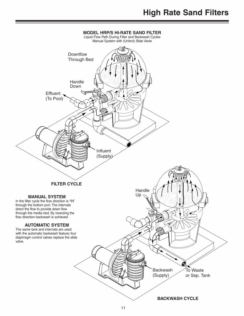
MODEL HRP/S HI-RATE SAND FILTERLiquid Flow Path During Filter and Backwash Cycles
Manual System with (Unitrol) Slide Vavle
FILTER CYCLE
BACKWASH CYCLE
MANUAL SYSTEMIn the filter cycle the flow direction is “IN”through the bottom port. The internalsdirect the flow to provide down flowthrough the media bed. By reversing theflow direction backwash is achieved.
AUTOMATIC SYSTEMThe same tank and internals are usedwith the automatic backwash feature; fourdiaphragm control valves replace the slidevalve.

High Rate Sand Filters
12
BASIC PRINCIPLE OF OPERATION
The Hi-Rate permanent media pressure filter operates at ratesseven to ten times higher than conventional rapid sand filters.
Figure 1 shows diagramatically the Hi-Rate permanent media fil-ter and Figure 2 shows a conventional sand filter operating ataccelerated flow rates. The units differ in two main respects:
1. Distribution and collection equipment is designed on scientific prin-ciples in the Hi-Rate, whereas the rapid sand filter uses a simplifiedform of inlet baffling and filtered water collection.
2. The sand filter has many grades of rock, gravel and sand, whereasthe Hi-Rate permanent media filter by using one grade of workingmedia provides a greater working depth in a tank of equal size.
With the scientific, balanced hydraulic flow design of the perma-nent media filter, water turbulence is reduced to very low limits,thus flow paths at the media surface are almost wholly paralleland vertical. It is observed that flow rates in excess of 20 gpm/sq.ft. can be applied to the Hi-Rate filter without displacing media orcausing channeling which occurs in the conventional unit.
At high flow rates, collected solids are forced deep into themedia, but selection of a fine media particle size enables goodfiltration to be achieved. A conventional sand filter retains the col-lected solids in the top 3/4” of the bed. The same volume ofsolids can be collected in a Hi-Rate filter on a much reduced sur-face area, as the full depth of the media is utilized.
The Hi-Rate permanent media filter is cleaned when the differ-ential pressure reaches 15 to 20 psi.
Our underdrain system in the Hi-Rate is designed to createstrong agitation in the working media during backwash. Mediagrains are rubbed together to release solids and circulation pat-terns are established to progressively cause each particle of themedia to rise to the surface of the bed at least once every minuteduring the backwash cycle. The balanced-flow conditionsinduced by our collector system insures that the up flow watervelocity during backwash is equal to that of the settling rate ofthe media grain thereby preventing media loss while insuringgood cleaning. Bed expansion is approximately 6” at backwashrates of 15 gpm/sq. ft. Complete fluidization of the media allowscollection solids to be discharged during the first 90 seconds ofbackwash. The recommended backwash period is 2 to 4 minutesto insure complete removal of collected solids.
Figure 1
HI-RATE FILTER
Scientifically engineered over and underdrains allow high velocity par-allel flow through the filter with a minimum of turbulence.
Figure 2
CONVENTIONAL SAND FILTER
Simplified over and underdrain in regular sand filter with its many lay-ers of rock and sand causes turbulence and channeling at high flowrates.

High Rate Sand Filters
13
RESIDENTIAL AND COMMERCIAL HI-RATE PERMANENTMEDIA FILTERS
Scientifically engineered over and underdrains in the vertical Hi-Ratepermanent media filter produces a high velocity parallel flow throughthe filter with a minimum of turbulence. Only one layer of media pro-vides a greater depth of filtering medium.
The Hi-Rate permanent media filter operates at flow rates from 15gpm to 20 gpm per square foot of filter area. The backwash flow ratesare the same as for the filtering cycle.
When selecting a Hi-Rate filter, multiple tanks of the same size maybe combined for increased capacity.
Tank Size Grade #20 Silica Sand
Model Approximate Number of Weight inNumber Diameter Height Freeboard Sacks Req. Pounds
HRPB20 20” 34” 11” 2 200
S7S50 28.5” 42” 11” 2 200
HRPB24 24” 34” 11” 2.5 250
S8S70 32.5” 42.25” 11” 3 300
HRPB30 30” 34” 11” 4 400
FILTER MEDIA REQUIREMENT CHART FOR SYSTEM 3 SAND FILTERS
NOTE: 1 cu. ft. of silica sand equals 1 sack or approximately 100 pounds. Freeboard is the open areabetween the top of the filter sand and the backwash outlet of the tank. During the first few backwashes,the lighter particles of sand and any excess will be flushed from the tank. DO NOT use a finer grade offilter media than specified.
Sieve Analysis
Grade #20 Silica Sand
TylerSieve No. % Retained
20 2
30 58
40 36
50 4
— —
— —
Effective Size –.45 mmUniformity coefficient
1.5 maximum
FILTER MEDIA FOR VERTICAL HI-RATE FILTERS

High Rate Sand Filters
14
STA-RITE
Total Flow Rate at 15 GPM per Sq. Ft. of Filter Area Flow Rate at 20 GPM per Sq. Ft. of Filter Area
Model Sq. Ft. ofNumber Filter Area GPM GP 6 Hours GP 8 Hours GPM GP 6 Hours GP 8 Hours
S7S50 2.436 12,960 17,800 – – –
– – – 48 17,280 23,040
S8S70 3.451 18,360 24,480 – – –
– – – 68 24,480 32,640
HRPB30 4.974 26,640 35,520 – – –
– – – 98 35,280 47,040
Model No. of Filter Area Flow Rate Turnover Rate Manifold 7 f.p.s.Number Units Sq. Ft. 15 GPM 20 GPM 6 Hours 8 Hours Pipe Size GPM Silica Sand
2 9.8147 – 52,920 70,560 3” 441
800– 196 70,560 94,080 3” 588
3 14.7220.5 – 79,380 105,840 4” 662
1200– 294 105,840 141,120 4” 882
4 19.6394 – 105,840 141,120 4” 882
1600– 392 141,120 188,160 4” 1,176
HRPB30 5 24.5367.5 – 132,300 176,400 6” 1,103
2000– 480 176,400 235,200 6” 1,440
6 29.4441 – 158,760 211,680 6” 1,323
2400– 588 211,680 282,240 6” 1,764
7 34.3514.5 – 185,220 246,960 6” 1,544
2800– 686 246,960 329,280 6” 2,058
8 39.2588 – 211,680 282,240 6” 1,764
3200– 784 282,240 376,320 6” 2,352
SR-300-2U 1 4.974 – 26,640 35,520 2” 74
550– 98 35,280 47,040 2-1/2” 105
SR-360-2U 1 7.1106 – 38,160 50,880 2-1/2” 105
875– 142 51,120 68,160 3” 165
SR-360-3T 1 7.1106 – 38,160 50,880 2-1/2” 105
875– 142 51,120 68,160 3” 165
RESIDENTIAL HI-RATE PERMANENT MEDIA FILTER RATE AND CAPACITY CHART
NOTES: Recommended flow rate – 15 gpm per sq. ft. of filter area.Recommended Velocity of Schedule 40 Rigid PVC Pipe is 7 fps. Check local codes.100 lbs. of #20 Silica Sand is one bag. 1 bag is approximately 1 cu. ft.Backwash Gallons is based on minimum of 3 minutes in the backwash cycle.
SYSTEM 3Model S7S50Model S8S70HRPB30
HRPB and SYSTEM 3Sand Filters

High Rate Sand Filters
15
3497 0899
Sq. Ft. 15 GPM 20 GPM Gallons Gallons GallonsCatalog of Filter per Sq. Ft. per Sq. Ft. per per perNumber Area Rate Rate 4 Hours 6 Hours 8 Hours
21603-1042 9.26139 – 33,360 50,040 66,720
– 186 44,640 66,960 89,280
21603-1047 12.17182 – 43,680 65,820 87,360
– 244 58,560 87,840 117,120
21603-1055 16.56249 – 59,760 89,640 119,520
– 332 79,680 119,520 159,360
21603-1063 21.63325 – 78,000 50,040 66,720
– 432 44,640 117,000 156,000
21603-1071 27,38410 – 98,400 149,600 196,800
– 546 131,040 176,560 262,080
21603-1079 33.80507 – 121,680 182,520 243,360
– 676 162,240 243,360 324,470
21603-1093 46.72701 – 168,240 252,360 336,480
– 934 224,160 336,240 448,320
FILTER CAPACITY – VERTICAL
Face Lbs.Sq. Ft. 15 U.S. GPM U.S. Gals. U.S. Gals. U.S. Gals. Piping #20 Filter Approx.
Catalog of Filter per Sq. Ft. Per Per Per Size Sand ShippingNumber Area Rate 4 Hours 6 Hours 8 Hours (I.P.S.) Required Wt. Lbs.
24601-36143 14.3 215 GPM 51,600 77,400 103,200 N/A 2,300 630
24601-36173 17.3 260 GPM 62,400 93,600 124,800 N/A 2,800 740
24601-36203 20.3 305 GPM 73,200 109,800 146,400 N/A 2,600 830
FILTER CAPACITY – HORIZONTAL
NOTE: Filter Media and pumping equipment ARE NOT included with filter tanks.ENGINEERING NOTES: The Vertical Hi-Rate Filter(s) should be backwashed when a 15 P.S.I.G. (104 to 117 kPa) differential is indicated on theinfluent and effluent pressure gauges.When sizing the main recirculating pump for the Vertical Hi-Rate Filter(s), calculate head loss for maximum dirt load at 15 to 20 P.S.I.G. (104 to138 kPa) through the filter and face piping.
* For other sizes call for quote.
VERTICAL HORIZONTAL

Modular Media for Commercial Applications
16
Filter Capacity Dirt Filter DimensionsNo. Filter at Max. Flow Rate Loading in Inches
Model of Area Flow Capacity Tank Service Tank ServiceNumber Tanks Sq. Ft. GPM 6 Hours 8 Hours Rate* in Lbs. Width Width Height Height
1 300 100 36,000 48,000 35
2 600 200 72,000 96,000 70
3 900 300 108,000 144,000 105
4 1,200 400 144,000 192,000 140S7M120
5 1,500 500 180,000 240,000 17528.5 36 42 68
6 1,800 600 216,000 288,000 210
7 2,100 700 252,000 336,000 245
8 2,400 800 288,000 384,000 280
1 450 125 45,000 60,000 55
2 900 250 90,000 120,000 110
3 1,350 375 135,000 180,000 165
4 1,800 500 180,000 240,000 220S8M150
5 2,250 625 225,000 300,000 27532.5 40 42.25 68
6 2,700 750 270,000 360,000 330
7 2,100 875 312,000 420,000 385
8 2,400 1,000 360,000 480,000 400
* Flow rate at maximum GPM per square foot of filter area.
.333
.278
SYSTEM 3Model S7M120Model S8M150

Head Loss Charts
17
Component GPM Head Loss (Ft.) Component GPM Head Loss (Ft.)
Main drain 20 0.5 Skimmer 20 1.01-1/2” 30 1.0 1-1/2” 30 2.0Outlet 40 1.5 40 3.0
50 2.0 50 4.060 2.5 60 5.5
Main drain 40 1.0 Skimmer 20 0.52” 50 1.5 2” 30 1.0
Outlet 60 2.0 Outlet 40 2.070 3.0 50 3.080 4.0 60 4.0
70 5.0Heater – 7.0 Average 80 6.0
Backwash Valves
1-1/2” Push/Pull 50 6.0 1-1/2” Multiport 50 5.075 13.5 75 10.0
2” Push/Pull 75 7.0 2” Multiport 75 3.5120 17.6 100 6.0
120 8.5
Cartridge Filters GPM (.75) Head Loss (Ft.) GPM (.375) Head Loss (Ft.)
25 sq. ft. 18.75 1.1 9.38 7.0 Average35 sq. ft. 26.25 2.0 13.13 7.0 Average50 sq. ft. 37.50 4.3 18.75 7.0 Average70 sq. ft. 52.50 7.5 26.25 7.0 Average75 sq. ft. 56.25 8.0 28.13 7.0 Average100 sq. ft. 75.00 17.5 37.50 7.0 Average135 sq. ft. 101.25 28.0 50.63 7.0 Average
Sand Filters GPM (20) Head Loss (Ft.) GPM (15) Head Loss (Ft.)
14” 1.05 sq. ft. 21.0 10 (est.) 15.8 7.0 Average16” 1.41 sq. ft. 28.2 12 (est.) 21.2 7.0 Average18” 1.80 sq. ft. 36.0 14 (est.) 27.0 7.0 Average20” 2.20 sq. ft. 44.0 16 33.0 7.0 Average22” 2.66 sq. ft. 53.2 18 (est.) 39.9 7.0 Average24” 3.10 sq. ft. 63.0 25 46.5 7.0 Average30” 4.90 sq. ft. 98.0 17 73.5 7.0 Average36” 7.10 sq. ft. 142.0 24 (est.) 106.5 7.0 Average
Modular Media Filters GPM Head Loss (Ft.) GPM (.375) Head Loss (Ft.)
100 sq. ft. “Mini Mods.” 75 6.0 38 1.5125 sq. ft. “Mini Mods.” 94 9.0 47 2.5150 sq. ft. “Mini Mods.” 113 12.0 56 3.5175 sq. ft. “Mini Mods.” 131 16.0 66 4.5200 sq. ft. “Mini Mods.” 150 20.0 75 6.0300 sq. ft. “Mini Mods.” 150 20.0 113 13.0
Modular D.E. Filters GPM (1.5) Head Loss (Ft.) GPM (NSF) Head Loss (Ft.)
36 sq. ft. 54 5.5 70 9.060 sq. ft. 90 7.0 120 13.072 sq. ft. 108 10.0 144 18.0
Modular Media Filters GPM (NSF) Head Loss (Ft.)
200 sq. ft. - System3 100 3.0400 sq. ft. - System3 115 4.6450 sq. ft. - System3 124 5.5500 sq. ft. - System3 130 6.3

Head Loss Charts
18
1.0” (1.0 ID)
Velocity Exit Head Velocity Exit Head Velocity Exit HeadGPM FPS (Ft.) GPM FPS (Ft.) GPM FPS (Ft.)
15 6.13 .58 27 11.03 1.89 39 15.93 3.9516 6.54 .66 28 11.44 2.03 40 16.34 4.1517 6.95 .75 29 11.85 2.18 41 16.75 4.3618 7.35 .84 30 12.26 2.34 42 17.16 4.5819 7.76 .94 31 12.66 2.49 43 17.57 4.8020 8.17 1.04 32 13.07 2.66 44 17.98 5.0221 8.58 1.14 33 13.48 2.83 45 18.38 5.2522 8.99 1.26 34 13.89 3.00 46 18.79 5.4923 9.40 1.37 35 14.30 3.18 47 19.20 5.7324 9.81 1.50 36 14.71 3.36 48 19.61 5.9825 10.21 1.62 37 15.12 3.55 49 20.02 6.2326 10.62 1.75 38 15.52 3.75 50 20.43 6.49
3/8” (.375 ID)
Velocity Exit HeadGPM FPS (Ft.)
1 2.91 .132 5.81 .533 8.71 1.184 11.62 2.105 14.53 3.286 17.43 4.727 20.34 6.438 23.24 8.409 26.15 10.63
10 29.05 13.12
1/2” (.50 ID)
Velocity Exit HeadGPM FPS (Ft.)
5 8.17 1.046 9.80 1.497 11.44 2.038 13.07 2.669 14.71 3.36
10 16.34 4.1511 17.98 5.0212 19.61 5.9813 21.24 7.0214 22.88 8.1415 24.51 9.3416 26.15 10.6317 27.78 12.0018 29.41 13.4519 31.05 14.9920 32.68 16.61
3/4” (.75 ID)
Velocity Exit HeadGPM FPS (Ft.)
5 3.63 .216 4.36 .307 5.08 .418 5.81 .539 6.54 .67
10 7.27 .8211 7.99 .9912 8.72 1.1813 9.44 1.3914 10.17 1.6115 10.89 1.8516 11.62 2.1017 12.35 2.3718 13.07 2.6619 13.80 2.9620 14.53 3.2821 15.25 3.6222 15.98 3.9723 16.70 4.3424 17.43 4.7225 18.16 5.1326 18.88 5.5427 19.60 5.9828 20.34 6.4329 21.06 6.9030 21.79 7.38
7/8” (.875 ID)
Velocity Exit HeadGPM FPS (Ft.)
10 5.34 .4411 5.87 .5412 6.40 .6413 6.94 .7514 7.47 .8715 8.00 1.0016 8.54 1.1317 9.07 1.2818 9.60 1.4319 10.14 1.6020 10.67 1.7721 11.21 1.9522 11.74 2.1423 12.27 2.3424 12.81 2.5525 13.34 2.7726 13.87 2.9927 14.41 3.2328 14.94 3.4729 15.47 3.7230 16.01 3.9831 16.54 4.2532 17.08 4.5333 17.61 4.8234 18.14 5.1135 18.68 5.4236 19.21 5.7437 19.74 6.0638 20.28 6.3939 20.81 6.7340 21.34 7.08
EXIT LOSS CHARTS
Self Priming Pumps
19
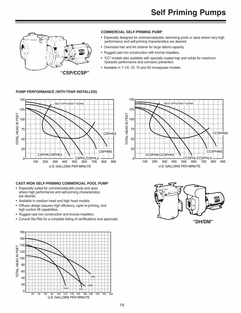
CAST IRON SELF-PRIMING COMMERCIAL POOL PUMP• Especially suited for commercial/public pools and spas
where high performance and self-priming characteristics are desired.
• Available in medium head and high head models.• Diffuser design assures high efficiency, rapid re-priming, and
high suction lift capabilities.• Rugged cast iron construction and bronze impellers.• Consult Sta-Rite for a complete listing of certifications and approvals.
150
125
100
75
50
20
0100 200 300 400 500 600 700 800 900
BEST EFFICIENCY SIZING
U.S. GALLONS PER MINUTE
TOTA
L H
EA
D IN
FE
ET
CSPHK/CSPHK3CSPHL/CSPHL3
CSPHN3
CSPHM3
150
125
100
75
50
20
0100 200 300 400 500 600 700 800 900
BEST EFFICIENCY SIZING
U.S. GALLONS PER MINUTE
TOTA
L H
EA
D IN
FE
ET
CCSPHK/CCSPHK3CCSPHL/CCSPHL3
CCSPHN3
CCSPHM3
180
160
140
120
100
80
60
40
20
0
TOTA
L H
EA
D IN
FE
ET
20 40 60 80 100 120 140 160 180 200 220 240 260
U.S. GALLONS PER MINUTE
DHH DHJ
DMH
DMJ
“CSP/CCSP”
COMMERCIAL SELF-PRIMING PUMP
• Especially designed for commercial/public swimming pools or spas where very highperformance and self-priming characteristics are desired.
• Oversized hair and lint strainer for large debris capacity.
• Rugged cast iron construction with bronze impellers.
• “CC” models also available with specially coated trap and volute for maximumhydraulic performance and corrosion prevention.
• Available in 7-1/2, 10, 15 and 20 horsepower models.
PUMP PERFORMANCE (WITH TRAP INSTALLED)
“DH/DM”

Type “B” Centrifugal Pumps
20
MOTOR DRIVE
Berkeley Type “B” centrifugal pumps are back pull-out design. Removalof easily accessible bolts permit access to the impeller without disturb-ing the piping. These motor driven pumps are ideal for most industrialand agricultural installations that require high performance, easy main-tenance and moderate initial cost.
Sizes: Tapped Discharge – 1 inch through 3 inches NPT;Flanged Discharge – 4 inches through 10 inches.Capacitites to 5000 gallons per minute; Heads to 500 feet.
See Centrifugal Accessories for additional components needed tomake a complete installation.
Features
1. VOLUTE CASE – Precision machined gray cast iron, engineered tomodern hydraulic standards. Discharge may be rotated to any of fourpositions for convenience in piping.
2. BRACKET – Heavy cast iron bracket maintains positive shaft align-ment between motor and impeller.
3. IMPELLER – Enclosed type impeller is balanced to provide smoothoperation. Impeller is keyed to shaft and locked with special capscrew and washer.
4. SHAFT SEAL – Extra deep stuffing box with adjustable gland isstandard and provides extra protection against leakage, prolongsshaft life. The shaft is protected through the stuffing box by a stain-less steel sleeve. Rotary mechanical seals are available. Themechanical seal unit is identified by the letter “S” at the end of themodel number.
5. MOTOR – NEMA standard close coupled pump motors available at1180, 1760 and 3450 RPM. Entire rotating element of the pump isbuilt directly on the motor shaft, minimizing shaft over-hang andassuring positive alignment. Incorporation of slinger ring providesextra protection for motor bearings. Special motor constructions areavailable to meet specific requirements.
1134 0694 A

Type “B” Centrifugal Pumps
21
End-SuctionCentrifugal
Pumps
– 320
– 300
– 250
– 200
– 150
– 100
– 50
– 0
–
80 –
–
60 –
–
40 –
–
20 –
–
0 –0 100 200 300 400 500 600 700 800
0 20 40 60 80 100 120 140 160
U.S. gpm
M /hr3
Mete
rs
Feet
CAPACITY
TOTA
L H
EA
D
COMPOSITE PUMP CURVES
A. B11⁄2TQMS-9
B. B11⁄2TQMS-10BB1111⁄⁄22ZZQQLLSS--1188
BB11WWQQSS--99 BB2211⁄⁄22ZZQQMMSS--
BB22EEQQLLSS--3300
BB33ZZQQMMSS--3300BB33TTQQMMSS--1188
BB33TTQQMMSS--1144
BB22ZZQQLLSS--1188BB11 11⁄⁄22 TTQQMMSS--1144
BB11 11⁄⁄22 ZZQQLLSS--1144
BB11 11⁄⁄22 TTQQMMSS--88
BA
BB2211 ⁄⁄ 22TT
QQMMSS--1144
BB22TTQQMMSS--1144
Hair and Lint TrapsFor Commercial Pumps• Bronze or Cast Iron
• 6", 8", 9-1/2" or 11" Trap Diameters
Suction Ship Wt.Package No. Description Port Size (lbs.)51 6" Cast Iron Trap with Basket 2" NPT 2056 6" Bronze Trap with Basket 2" NPT 2098 8" Cast Iron Trap with Basket 3" NPT 4099 8" Bronze Trap with Basket 3" NPT 4076 Cast Iron Flange for a Remote Installation of 8" Trap 3" NPT 474 11" Cast Iron Trap with Basket 3" NPT 65184 1100 cu. in. Hair & Lint Strainer 6" Flange 180184C 1100 cu. in. Hair & Lints Strainer (coated) 6" Flange 180
6" Cast Iron or Bronze Trap(Pkg. 51/56/94)
8" Cast Iron or Bronze Trap(Pkg. 98/99)

Installation Considerations
22
ARRANGEMENT RECOMMENDED
Short length of straight pipe after reducer.( 2 times pipe diameter minimum )
SuctionGauge
Seefoundationsection.
Eccentric Reducerflat side up.
Return to Pool -One size largerthan Pump Dischargeport to reduce friction
IsolationValve
Straight run, as short as possible but at least 6 times the pipe diameter ("D") after strainer to stabilize flow.
3080 1097
NOTICE: All connectionsmust be air tight.
Standardor longradius elbow.
To PumpSuction
Notto
Scale
Support pipe as required
55G
PM
LISTEDSUCTIONFITTING
ST
A-R
ITE
080
10-001055
G
PM
LISTEDSUCTIONFITTING
ST
A-R
ITE
080
10-0010
FlowThroughSkimmer
Equalizer Fitting
IsolationValve
Flow-ThroughStrainer
No shutoff valve betweenTee and Main Drains
All suction outlets must havecorrectly installed, screw-fastenedcovers in place.
Installation Considerations
23
LOCATION OF UNIT
The pump unit should be located as near the source of water aspractical to minimize the vertical lift of water to the pump and so thata short, direct suction pipe with a minimum number of fittings can beused to keep the pipe friction energy loss as low as possible.
Both the suction and discharge pipes should be naturally aligned withthe pump and independently supported near the inlet and dischargeflanges to prevent strain on the pump case.
The pump unit must be adequately supported to prevent movementduring operation.
The motor feet should be mounted on an elevated pad, 3 to 4 incheshigh, to prevent water from accumulating under the motor air intakeopenings.
SUCTION PIPING
General
TYPE – Use pipe, tubing or wire-reinforced hose with sufficientstrength to resist collapse under atmospheric pressure differential. Alljoints must be air tight.
SUCTION PIPE SIZE – Satisfactory operation will depend on controlof pipe friction loss within acceptable limits. The minimum size of suc-tion pipe to be used can be determined by a comparison of NPSHAVAILABLE at the pump inlet, against the NPSH REQUIRED by theimpeller, as shown on the pump performance curve (for details onprocedure for NPSH comparisons, see Berkeley Pump Company,Engineering Spec. 0307, which is available on request).
Generally, satisfactory results will be obtained when the average flowvelocity is less than 10 feet/second which may require that the suc-tion pipe be larger than the suction opening of the pump.
Local conditions (elevation above sea level, suctionlift elevation, vapor pressure of liquid, etc.) may
require a reduction of velocity by increasing pipe size.
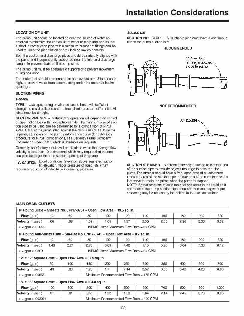
Suction Lift
SUCTION PIPE SLOPE – All suction piping must have a continuousrise to the pump suction inlet.
SUCTION STRAINER – A screen assembly attached to the inlet endof the suction pipe to exclude objects too large to pass thru thepump. The strainer should have a free, open area of at least threetimes the area of the suction pipe. A strainer is often combined with afoot valve to retain the prime when the pump is stopped.NOTE: If great amounts of solid material can occur in the liquid as itapproaches the pump suction pipe, then one or more stages of pre-screening may be necessary in addition to the suction strainer.
RECOMMENDED
NOT RECOMMENDED
8” Round Grate – Sta-Rite No. 07017-0751 – Open Flow Area = 19.5 sq. in.
Flow (gpm) 40 60 80 100 120 140 160 180 200 220
Velocity (ft./sec.) .66 .99 1.32 1.65 1.97 2.30 2.63 2.96 3.30 3.62
v = gpm x .01645 IAPMO Listed Maximum Flow Rate = 80 GPM
8” Round Anti-Vortex Plate – Sta-Rite No. 07017-0741 – Open Flow Area = 8.7 sq. in.
Flow (gpm) 40 60 80 100 120 140 160 180 200 220
Velocity (ft./sec.) 1.48 2.21 2.95 3.69 4.42 5.15 5.90 6.64 7.38 8.12
v = gpm x .0369 IAPMO Listed Maximum Flow Rate = 60 GPM
12” x 12” Square Grate – Open Flow Area = 37.5 sq. in.
Flow (gpm) 50 100 150 200 250 300 350 400 500 700
Velocity (ft./sec.) .43 .86 1.28 1.71 2.14 2.57 3.00 3.42 4.28 6.00
v = gpm x .00855 Maximum Recommended Flow Rate = 175 GPM
18” x 18” Square Grate – Open Flow Area = 104.8 sq. in.
Flow (gpm) 100 200 300 400 500 600 700 800 900 1,000
Velocity (ft./sec.) .31 .61 .92 1.22 1.53 1.84 2.14 2.45 2.76 3.06
v = gpm x .003061 Maximum Recommended Flow Rate = 490 GPM
MAIN DRAIN OUTLETS

Installation Considerations
24
FLOODED SUCTION
A gate valve is used in a pressurized suction pipe as an isolationvalve to permit servicing the pump. Use a bleed valve on top of thepump volute case to allow trapped air to escape.
DISCHARGE PIPING
TYPE – Use pipe, tubing or hose with sufficient strength to containthe highest anticipated operating pressure.
DISCHARGE PIPE SIZE – Because of the increasingly high cost ofthe additional energy necessary to overcome the larger friction loss-es of small pipe, the discharge pipe size is commonly one or morenominal pipe sizes larger than the discharge opening of the pump.
To determine the optimum size of the discharge pipe, compare thetotal cost of the operating system (sum of the pump with driver con-trol, plus the cost of the pipe, plus the cost of the power projected forthe term of operation), for several adjacent pipe sizes.
The number of pipe fittings (elbows, tees, etc.) should be kept to aminimum to avoid needless energy loss.
PIPE ALIGNMENT – Piping and fittings must be naturally alignedwith the pump openings and independently supported to preventstrain on the pump and driver unit. If necessary, restrain piping sys-tem and/or provide expansion joints to protect pump unit againstexcessive thermal or pressure growth forces.
DISCHARGE FLOW CONTROL VALVE – For throttling of dischargefor flow rate control.
RECOMMENDED
NOT RECOMMENDED

Installation Considerations
25
DISHCARGE CHECK VALVE – To prevent back flow through thepump during operation.
DISCHARGE PRIMING VALVE – Isolates pump case from atmos-phere during air evacuation type priming.
RECOMMENDED NOT RECOMMENDED
RECOMMENDED
RECOMMENDED
NOT RECOMMENDED
Installation Considerations
26
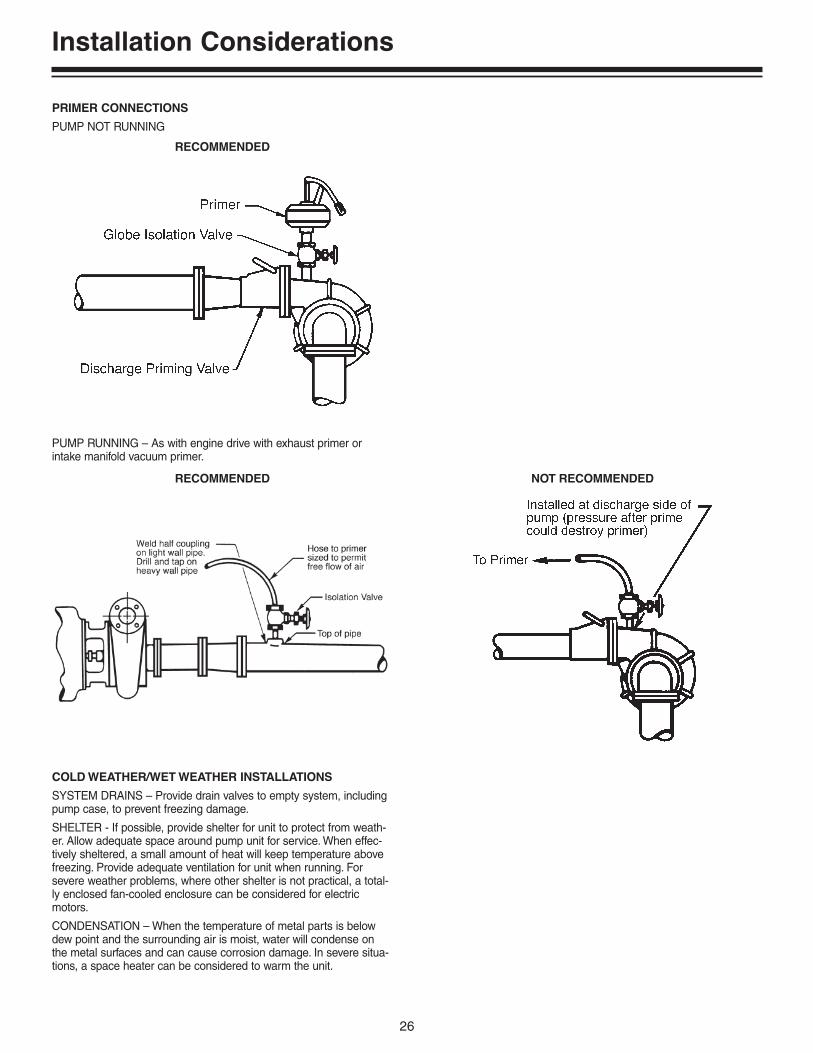
PRIMER CONNECTIONS
PUMP NOT RUNNING
PUMP RUNNING – As with engine drive with exhaust primer orintake manifold vacuum primer.
COLD WEATHER/WET WEATHER INSTALLATIONS
SYSTEM DRAINS – Provide drain valves to empty system, includingpump case, to prevent freezing damage.
SHELTER - If possible, provide shelter for unit to protect from weath-er. Allow adequate space around pump unit for service. When effec-tively sheltered, a small amount of heat will keep temperature abovefreezing. Provide adequate ventilation for unit when running. Forsevere weather problems, where other shelter is not practical, a total-ly enclosed fan-cooled enclosure can be considered for electricmotors.
CONDENSATION – When the temperature of metal parts is belowdew point and the surrounding air is moist, water will condense onthe metal surfaces and can cause corrosion damage. In severe situa-tions, a space heater can be considered to warm the unit.
RECOMMENDED
RECOMMENDED NOT RECOMMENDED

Hydraulic Charts and Tables
27
Natural Gas Heater Sizing
TemperatureRise: 10° 15° 20° 25° 30°Pool Size Heat Loss = Required HeaterSq. Ft. Output (BTUs/Hour)
200 55,900 83,800 111,840 139,800 167,760300 83,880 125,820 127,760 209,700 251,640400 111,850 167,775 223,700 279,625 335,550500 139,810 209,715 279,620 349,525 419,430600 167,770 251,655 335,540 419,435 503,310700 195,720 293,595 391,460 489,325 587,190800 223,690 335,535 447,380 559,225 671,070900 251,650 377,475 503,300 629,125 754,9501000 279,610 419,415 559,220 699,025 838,830
Initial Heat Up – BTU Required - 24 Hrs
Note: Chart prepared by the Commercial Water Heating Sub-committee of the American Gas Association in Oct. 1995.
TemperatureRise: 10° 15° 20° 25° 30°Pool Size Heat Loss = Required HeaterSq. Ft. Output (BTUs/Hour)
200 21,000 31,500 42,000 52,500 63,000300 31,500 47,250 63,000 78,750 94,500400 42,000 63,000 84,000 105,000 126,000500 52,500 78,750 105,000 131,250 157,500600 63,000 94,500 126,000 157,500 189,000700 73,500 110,250 147,000 183,750 220,500800 84,000 126,000 168,000 210,000 252,000900 94,500 141,750 189,000 236,250 283,5001000 105,000 157,500 210,000 262,500 315,000
BTU Required to Maintain Temperature
Note: Outdoors, 3.5 mph Wind.Note: Chart prepared by the Commercial Water Heating
Sub-committee of the American Gas Association in Oct. 1995.
Heater Heater Output (BTU/Hr)InputBTU/Hr 70% 75% 80% 85% 90%100,000 70,000 75,000 80,000 85,000 90,000200,000 140,000 150,000 160,000 170,000 180,000300,000 210,000 225,000 240,000 255,000 270,000400,000 280,000 300,000 320,000 340,000 360,000
Heater EfficienciesInput x % Efficiency
Formulas:Initial Heat Up in a 24 Hour PeriodGallons x 8.33 x Temp Rise = BTU x 24 hrs = Total BTU’s Required
Maintaining TemperaureUsing the chart at the upper right, determine the heat lossto maintain the desired temperature rise. Then, divide theheat loss BTU’s by the heater efficiency.126,000 BTU ÷ 80% = 157,500 BTU (Heater Size)
Minutes for 30° F Temperature Rise (Heater Input In 1000 BTU/HR)
Spa Volume (Gallons) SR200NA SR333NA SR400NA200 18 11 9300 27 16 13400 35 21 18500 44 27 22600 53 32 27700 62 37 31800 71 43 35900 80 48 401000 89 53 44
Spa Heater Sizing – Recommended Max-E-Therm Model
Note: The chart is based on a 30° F temperature rise, discounting losses and only based on heat requried to raise temperature in minutes.

Hydraulic Charts and Tables
28
Low Pressure Natural Gas & Propane Gas Pipe Size
BTU RPM CFM CFH100,000 3.3 1.67 100150,000 5.0 2.50 150200,000 6.7 3.34 200250,000 8.3 4.17 250300,000 10.0 5.00 300350,000 11.7 5.84 250400,000 13.3 6.67 400
Natural Gas Consumption Meter
Degrees Degrees Degrees Degrees Degrees Degrees Degrees Degrees
C F C F C F C F C F C F C F C F
0 32.0 13 55.4 26 78.8 39 102.2 52 125.6 65 149.0 78 172.4 91 195.8
1 33.8 14 57.2 27 80.6 40 104.0 53 127.4 66 150.8 79 174.2 92 197.6
2 35.6 15 59.0 28 82.4 41 105.8 54 129.2 67 152.6 80 176.0 93 199.4
3 37.4 16 60.8 29 84.2 42 107.6 55 131.0 68 154.4 81 177.8 94 201.2
4 39.2 17 62.6 30 86.0 43 109.4 56 132.8 69 156.2 82 179.6 95 203.0
5 41.0 18 64.4 31 87.8 44 111.2 57 134.6 70 158.0 83 181.4 96 204.8
6 42.8 19 66.2 32 89.6 45 113.0 58 136.4 71 159.8 84 183.2 97 206.6
7 44.6 20 68.0 33 91.4 46 114.8 59 138.2 72 161.6 85 185.0 98 208.4
8 46.4 21 69.8 34 93.2 47 116.6 60 140.0 73 163.4 86 186.8 99 210.2
9 48.2 22 71.6 35 95.0 48 118.4 61 141.8 74 165.2 87 188.6 100 212.0
10 50.0 23 73.4 36 96.8 49 120.2 62 143.6 75 167.0 88 190.4 –– ––
11 51.8 24 75.2 37 98.6 50 122.0 63 145.4 76 168.8 89 192.2 –– ––
12 53.6 25 77.0 38 100.4 51 123.8 64 147.2 77 170.6 90 194.0 –– ––
Centigrade and Fahrenheit Equivalents
Note: Each revolution of the ‘half cubic foot dial needle’= 1/2 cubic foot of gas.
RPM - 1 RPM = .5 CUBIC FEETCMF = CFM / 60 minutesCFH = BTU / 1,000BTU = CFH (1000) APPROXIMATELY
Heater Top Of BottomSize Room Of Room
100,000 100 Sq. In. 100 Sq. In.150,000 150 Sq. In. 150 Sq. In.200,000 200 Sq. In. 200 Sq. In.250,000 250 Sq. In. 250 Sq. In.300,000 300 Sq. In. 300 Sq. In.350,000 350 Sq. In. 350 Sq. In.400,000 400 Sq. In. 400 Sq. In.
Ventilation Requirements – Indoors
Note: Ventilation requirements are in addition to any other devicethat needs ventilation, such as a pump motor.
Heater Size Pipe Size
Impute BTU 0-50' 51-100' 100-200' 200-300'
100,000 3/4" 3/4" 1' 11⁄4"200,000 11⁄4" 11⁄4" 11⁄2" 11⁄2"300,000 11⁄4" 11⁄4" 11⁄2" 11⁄2"400,000 11⁄4" 11⁄2" 11⁄2" 11⁄2"
Hydraulic Charts and Tables
29
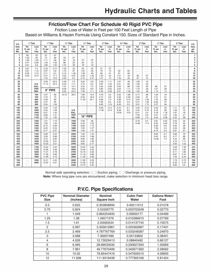
PVC Pipe Nominal Diameter Nominal Cubic Feet Gallons Water/Size (Inches) Square Inch Water Foot
0.5 0.622 0.303858694 0.00211013 0.015780.75 0.824 0.53326775 0.003703248 0.02770
1 1.049 0.864254945 0.00600177 0.044891.25 1.38 1.49571576 0.010386915 0.077691.5 1.61 2.03583534 0.014137745 0.105752 2.067 3.355612861 0.023302867 0.17431
2.5 2.469 4.787767769 0.033248387 0.248703 3.068 7.39267489 0.05133802 0.384014 4.026 12.73029413 0.08840482 0.661276 6.065 28.89033032 0.200627294 1.500698 7.961 49.77670499 0.345671562 2.5856210 10.02 78.85447416 0.547600515 4.0960512 11.938 111.9319439 0.777305166 5.81424
P.V.C. Pipe Specifications
U.S.3⁄4” Pipe 1” Pipe 11⁄4” Pipe 11⁄2” Pipe 2” Pipe 21⁄2” Pipe 3” Pipe 4” Pipe 6” Pipe U.S.
Gals. Vel. Loss Vel. Loss Vel. Loss Vel. Loss Vel. Loss Vel. Loss Vel. Loss Vel. Loss Vel. Loss Gals.per Ft. per in Ft. per in Ft. per in Ft. per in Ft. per in Ft. per in Ft. per in Ft. per in Ft. per in perMin. Sec. Feet Sec. Feet Sec. Feet Sec. Feet Sec. Feet Sec. Feet Sec. Feet Sec. Feet Sec. Feet Min.
1 .60 .25 .37 .07 . . . . . . . . . . . . . . . . . . . . . . . . . . . . . . . . . . . . . . . . . . . . . . . . . . . . . . . . 12 1.20 .90 .74 .28 .43 .07 . . . . . . . . . . . . . . . . . . . . . . . . . . . . . . . . . . . . . . . . . . . . . . . . 23 1.80 1.92 1.11 .60 .64 .16 .47 .07 . . . . . . . . . . . . . . . . . . . . . . . . . . . . . . . . . . . . . . . . 34 2.41 3.28 1.48 1.02 .86 .25 .63 .12 . . . . . . . . . . . . . . . . . . . . . . . . . . . . . . . . . . . . . . . . 45 3.01 5.8 1.86 1.52 1.07 .39 .79 .18 . . . . . . . . . . . . . . . . . . . . . . . . . . . . . . . . . . . . . . . . 5
6 3.61 7.0 2.33 2.15 1.29 .55 .95 .25 .57 .07 . . . . . . . . . . . . . . . . . . . . . . . . . . . . . . . . 68 4.81 11.8 2.97 3.6 1.72 .97 1.25 .46 .76 .14 .54 .05 . . . . . . . . . . . . . . . . . . . . . . . . 8
10 6.02 17.9 3.71 5.5 2.15 1.46 1.58 .69 .96 .21 .67 .09 . . . . . . . . . . . . . . . . . . . . . . . . 1015 9.02 37.8 5.57 11.7 3.22 3.07 2.36 1.45 1.43 .44 1.01 .18 .65 .07 . . . . . . . . . . . . . . . . 1520 . . . . . . . . 7.42 19.9 4.29 4.2 3.15 2.47 1.91 .74 1.34 .30 .87 .12 . . . . . . . . . . . . . . . . 20
25 . . . . 9.28 30.0 5.36 7.9 3.94 3.8 2.39 1.11 1.67 .46 1.08 .16 . . . . . . . . . . . . . . . . 2530 . . . . U.S. 11.14 42.0 6.43 11.1 4.73 5.2 2.87 1.55 2.01 .65 1.30 .23 . . . . . . . . . . . . . . . . 3035 . . . . GAL. 7.51 14.7 5.52 7.0 3.35 2.06 2.35 .88 1.52 .30 .88 .07 . . . . . . . . 3540 . . . . PER 8.58 18.9 6.30 8.9 3.82 2.63 2.64 1.11 1.73 .39 1.01 .09 . . . . . . . . 4045 . . . . MIN. 8” PIPE 9.65 23.5 7.09 11.1 4.30 3.28 3.01 1.39 1.95 .48 1.13 .12 . . . . . . . . 45
50 . . . . 700 4.37 .66 10.72 28.5 7.88 13.5 4.78 4.0 3.35 1.69 2.17 .58 1.26 .16 . . . . . . . . 5060 . . . . 750 4.70 .75 . . . . . . . . 9.46 18.9 5.74 5.6 4.02 2.36 2.60 .81 1.51 .21 . . . . . . . . 6070 . . . . 800 4.99 .82 . . . . . . . . 11.03 25.1 6.69 7.4 4.69 3.14 3.04 1.09 1.76 .28 . . . . . . . . 7080 . . . . 850 5.37 .95 . . . . . . . . . . . . . . . . 7.65 9.5 5.35 4.0 3.47 1.39 2.02 .37 . . . . . . . . 8090 . . . . 900 5.64 1.06 . . . . . . . . . . . . . . . . 8.60 11.8 6.03 5.0 3.91 1.73 2.27 .46 . . . . . . . . 90
100 . . . . 950 5.94 1.23 . . . . . . . . . . . . 9.56 14.4 6.70 6.1 4.34 2.10 2.52 .55 1.11 .07 100125 . . . . 1000 6.25 1.28 . . . . U.S. . . . . . . . . 11.95 21.8 8.38 9.2 5.42 3.19 3.15 .85 1.39 .12 125150 . . . . 1050 6.57 1.40 . . . . GAL. . . . . . . . . 10.05 12.8 6.51 4.5 3.78 1.18 1.67 .16 150175 . . . . 1100 6.89 1.51 . . . . PER . . . . . . . . . . . . . . . . 7.59 5.9 4.41 1.57 1.94 .21 175200 . . . . 1150 7.20 1.65 . . . . MIN. 10” PIPE . . . . . . . . . . . . . . . . 8.68 7.9 5.04 2.08 2.22 .28 200
225 . . . . 1200 7.51 1.79 . . . . 1500 5.99 .92 . . . . . . . . . . . . . . . . 9.76 9.4 5.67 2.52 2.50 .35 225250 . . . . 1250 7.82 1.94 . . . . 1600 6.40 1.03 . . . . . . . . . . . . . . . . 10.85 11.5 6.30 3.05 2.78 .42 250275 . . . . 1300 8.13 2.09 . . . . 1700 6.80 1.15 . . . . . . . . . . . . . . . . . . . . . . . . 6.93 3.6 3.05 .48 275300 . . . . 1350 8.45 2.23 . . . . 1800 7.20 1.27 . . . . . . . . . . . . . . . . . . . . . . . . 7.56 4.3 3.33 .58 300325 . . . . 1400 8.77 2.37 . . . . 1900 7.60 1.41 . . . . . . . . . . . . . . . . . . . . . . . . 8.19 5.0 3.61 .67 325
350 . . . . 1450 9.08 2.53 . . . . 2000 7.99 1.54 . . . . . . . . . . . . . . . . . . . . . . . . 8.82 5.7 3.89 .79 350375 . . . . 1500 9.39 2.68 . . . . 2100 8.39 1.68 . . . . . . . . . . . . . . . . . . . . . . . . 9.45 6.5 4.17 .88 375400 . . . . 1550 9.70 2.85 . . . . 2200 8.80 1.82 . . . . . . . . . . . . . . . . . . . . . . . . 10.08 7.3 4.44 .99 400425 . . . . 1600 10.00 3.01 . . . . 2300 9.20 1.99 . . . . . . . . . . . . . . . . . . . . . . . . . . . . . . . . 4.72 1.11 425450 . . . . 1650 10.32 3.21 . . . . 2400 9.60 2.17 . . . . . . . . . . . . . . . . . . . . . . . . . . . . . . . . 5.00 1.22 450
475 . . . . 1700 10.64 3.40 . . . . 2500 10.00 2.34 . . . . . . . . . . . . . . . . . . . . . . . . . . . . . . . . 5.28 1.36 475500 . . . . 1750 10.96 3.59 . . . . 2600 10.40 2.50 . . . . . . . . . . . . . . . . . . . . . . . . . . . . . . . . 5.55 1.50 500550 . . . . 1800 11.27 3.78 . . . . 2700 10.79 2.69 . . . . . . . . . . . . . . . . . . . . . . . . . . . . . . . . 6.11 1.80 550600 . . . . 1850 11.58 3.98 . . . . 2800 11.18 2.88 . . . . . . . . . . . . . . . . . . . . . . . . . . . . . . . . 6.67 2.10 600650 . . . . 1900 11.89 4.19 . . . . 2900 11.59 3.08 . . . . . . . . . . . . . . . . . . . . . . . . . . . . . . . . 7.22 2.44 650
700 . . . . 1950 12.21 4.40 . . . . 3000 11.99 3.28 . . . . . . . . . . . . . . . . . . . . . . . . . . . . . . . . 7.78 2.79 700750 . . . . 2000 12.52 4.61 . . . . 3100 12.39 3.32 . . . . . . . . . . . . . . . . . . . . . . . . . . . . . . . . 8.33 3.19 750800 . . . . . . . . . . . . . . . . . . . . 3200 12.79 3.35 . . . . . . . . . . . . . . . . . . . . . . . . . . . . . . . . 8.89 3.6 800
Friction/Flow Chart For Schedule 40 Rigid PVC PipeFriction Loss of Water in Feet per 100 Feet Length of Pipe
Based on Williams & Hazen Formula Using Constant 150. Sizes of Standard Pipe in Inches.
Normal safe operating selection; ■■ Suction piping; ■■ Discharge or pressure piping.Note: Where long pipe runs are encountered, make selection in minimum head loss range.

Hydraulic Charts and Tables
30
U.S.1⁄2” Pipe 3⁄4” Pipe 1” Pipe 11⁄4” Pipe 11⁄2” Pipe 2” Pipe 21⁄2” Pipe 3” Pipe 31⁄2” Pipe 4” Pipe
Gals. Vel. Loss Vel. Loss Vel. Loss Vel. Loss Vel. Loss Vel. Loss Vel. Loss Vel. Loss Vel. Loss Vel.per Ft. per in Ft. per in Ft. per in Ft. per in Ft. per in Ft. per in Ft. per in Ft. per in Ft. per in Ft. perMin. Sec. Feet Sec. Feet Sec. Feet Sec. Feet Sec. Feet Sec. Feet Sec. Feet Sec. Feet Sec. Feet Sec.
2 2.74 6.72 1.48 1.51 . . . . . . . . . . . . . . . . . . . . . . . . . . . . . . . . . . . . . . . . . . . . . . . . . . . . . . . . . . . .4 5.48 24.2 2.97 5.45 1.79 1.54 1.00 .39 .73 .177 . . . . . . . . . . . . . . . . . . . . . . . . . . . . . . . . . . . .6 8.23 51.2 4.45 11.5 2.68 3.34 1.50 .82 1.09 .375 .65 .107 . . . . . . . . . . . . . . . . . . . . . . . . . . . .8 11.0 86.9 5.94 19.6 3.57 5.69 2.00 1.39 1.45 .64 .87 .183 .61 .077 . . . . . . . . . . . . . . . . . . . .
10 13.7 132.0 7.42 29.6 4.46 8.60 2.50 2.10 1.82 .96 1.09 .276 .76 .115 .485 .039 . . . . . . . . . . . .
12 . . . . . . . . 8.91 41.5 5.36 12.0 3.00 2.94 2.18 1.35 1.30 .387 .91 .161 .572 .055 . . . . . . . . . . . .15 . . . . . . . . 11.1 62.7 6.7 22.9 3.76 4.45 2.72 2.04 1.63 .585 1.14 .243 .727 .083 .54 .035 . . . .18 13.4 87.9 8.03 25.5 4.50 6.25 3.27 2.86 1.96 .818 1.36 .340 .873 .116 .65 .056 . . . .20 5” PIPE 14.8 107 8.92 30.9 5.00 7.57 3.63 3.47 2.17 .996 1.51 .414 .97 .140 .72 .068 .5625 . . . . . . . . . . . . . . . . 11.2 58.8 6.25 11.4 4.55 5.25 2.71 1.51 1.9 .625 1.21 .212 .90 .103 .69530 .53 .025 . . . . . . . . 13.4 65.3 7.50 16.0 5.45 7.38 3.26 2.11 2.27 .874 1.44 .297 1.08 .145 .8435 .62 .034 . . . . . . . . 15.6 86.9 8.75 21.3 6.38 9.78 3.80 2.81 2.65 1.16 1.70 .396 1.26 .192 .973
40 .71 .043 17.9 111 10.0 27.3 7.26 12.5 4.35 3.59 3.03 1.49 1.94 .507 1.44 .246 1.1245 .795 .054 6” PIPE . . . . . . . . 11.2 33.9 8.26 15.6 4.89 4.46 3.41 1.86 2.18 .629 1.63 .306 1.2550 .88 .065 .62 .027 . . . . . . . . 12.5 41.3 9.08 18.9 5.43 5.41 3.79 2.25 2.42 .766 1.80 .372 1.4055 .973 .078 .676 .032 . . . . . . . . 13.7 49.2 10.0 32.0 5.98 6.44 4.16 2.68 2.67 .912 1.99 .443 1.5360 1.06 .091 .74 .039 . . . . . . . . 15.0 57.8 10.9 26.5 6.52 7.61 4.54 3.16 2.92 1.07 2.17 .522 1.6765 1.15 .106 .80 .044 . . . . . . . . 16.1 67.0 11.8 30.7 7.06 8.84 4.92 3.66 3.14 1.25 2.35 .604 1.81
70 1.23 .121 .86 .051 . . . . . . . . 17.5 77.1 12.7 35.3 7.61 10.1 5.30 4.20 3.39 1.43 2.53 .691 1.9575 1.33 .138 .923 .057 . . . . . . . . 18.8 87.4 13.6 40.1 8.15 11.5 5.68 4.79 3.64 1.62 2.70 .787 2.0880 1.41 .155 .98 .065 . . . . . . . . 20.0 98.2 14.5 45.2 8.69 12.9 6.05 5.36 3.88 1.83 2.89 .888 2.2385 1.50 .174 1.04 .072 . . . . . . . . 21.2 110 15.4 50.3 9.03 14.5 6.43 6.02 4.10 2.04 3.05 .992 2.3490 1.59 .193 1.11 .080 . . . . . . . . 22.5 122 16.3 55.9 9.78 16.1 6.81 6.53 4.33 2.27 3.25 1.10 2.5195 1.67 .213 1.20 .089 . . . . . . . . . . . . . . . . 17.2 62.0 10.3 17.8 7.19 7.38 4.57 2.51 3.42 1.21 2.64
100 1.76 .234 1.23 .098 . . . . . . . . . . . . . . . . 18.2 68.2 10.9 19.6 7.57 8.13 4.85 2.76 3.67 1.34 2.79110 1.95 .279 1.36 .117 . . . . . . . . 20.0 81.3 12.0 23.4 8.33 9.68 5.33 3.29 3.97 1.60 3.07120 2.11 .329 1.48 .137 8” PIPE . . . . . . . . 21.8 95.4 13.0 27.4 9.08 11.4 5.80 3.87 4.33 1.88 3.35130 2.3 .381 1.60 .159 . . . . . . . . . . . . . . . . 23.6 111 14.1 31.8 9.84 13.2 6.30 4.48 4.69 2.18 3.63140 2.47 .437 1.72 .182 .98 .047 . . . . . . . . 25.4 127 15.2 36.5 10.6 15.1 6.80 5.12 5.05 2.50 3.91150 2.65 .496 1.85 .207 1.05 .054 . . . . . . . . . . . . . . . . 16.3 41.5 11.3 17.2 7.27 5.87 5.41 2.84 4.19
160 2.82 .559 1.97 .234 1.12 .059 . . . . . . . . . . . . . . . . 17.4 46.7 12.1 19.4 7.75 6.58 5.78 3.20 4.47170 3.0 .626 2.08 .261 1.19 .067 . . . . . . . . . . . . . . . . 18.5 52.2 12.9 21.7 8.20 7.37 6.14 3.58 4.75180 3.16 .696 2.22 .290 1.26 .074 . . . . . . . . . . . . . . . . 19.6 58.3 13.6 24.1 8.60 8.18 6.50 3.97 5.02190 3.36 .769 2.34 .321 1.33 .082 . . . . . . . . . . . . . . . . 20.6 64.4 14.4 26.6 9.20 9.05 6.85 4.39 5.30200 3.52 .846 2.46 .353 1.41 .091 . . . . . . . . . . . . . . . . 21.7 70.5 15.1 29.3 9.70 9.96 7.22 4.84 5.58220 3.88 1.01 2.71 .421 1.55 .108 . . . . . . . . . . . . . . . . 23.9 84.1 16.7 34.9 10.6 11.9 7.94 5.78 6.14
240 4.23 1.18 2.96 .484 1.69 .126 . . . . . . . . . . . . . . . . 26.1 98.7 18.2 41.0 11.6 13.9 8.66 6.77 6.70260 4.58 1.37 3.20 .573 1.83 .147 . . . . . . . . . . . . . . . . 28.3 115 19.7 47.5 12.6 16.2 9.38 7.85 7.26280 4.94 1.57 3.45 .658 1.97 .168 . . . . . . . . . . . . . . . . . . . . . . . . 21.2 54.5 13.5 18.6 10.1 9.02 7.82300 5.29 1.79 3.69 .747 2.11 .191 . . . . . . . . . . . . . . . . . . . . . . . . 22.7 62.0 14.4 21.1 10.8 10.2 8.38320 5.64 2.01 3.94 .841 2.24 .215 . . . . . . . . . . . . . . . . . . . . . . . . 24.2 69.9 15.5 23.7 11.5 11.5 8.94340 5.99 2.26 4.19 .940 2.39 .240 . . . . . . . . . . . . . . . . . . . . . . . . 25.8 78.2 16.3 26.6 12.3 12.9 9.50
360 6.35 2.51 4.43 1.05 2.64 .261 . . . . . . . . . . . . . . . . . . . . . . . . 27.2 86.9 17.4 29.5 13.0 14.3 10.0380 6.70 2.77 4.68 1.16 2.68 .295 . . . . . . . . . . . . . . . . . . . . . . . . 28.8 96.1 18.6 32.6 13.7 15.8 10.6400 7.05 3.05 4.93 1.27 2.81 .325 . . . . . . . . . . . . . . . . . . . . . . . . 30.3 106 19.4 35.9 14.4 17.4 11.2450 7.95 3.79 5.54 1.58 3.16 .404 . . . . . . . . . . . . . . . . . . . . . . . . . . . . . . . . 21.8 44.6 16.2 21.6 12.5500 8.82 4.61 6.16 1.92 3.51 .493 . . . . . . . . . . . . . . . . . . . . . . . . . . . . . . . . 23.2 54.1 18.1 26.3 14.0550 9.70 5.50 6.77 2.29 3.86 .587 . . . . . . . . . . . . . . . . . . . . . . . . . . . . . . . . 26.5 64.9 19.9 31.4 15.3
600 10.6 6.44 7.39 2.69 4.22 .686 . . . . . . . . . . . . . . . . . . . . . . . . . . . . . . . . 29.1 76.1 21.7 36.9 16.7650 11.5 7.47 8.00 3.12 4.57 .799 . . . . . . . . . . . . . . . . . . . . . . . . . . . . . . . . . . . . . . . . 23.5 42.8 18.1700 12.3 8.60 8.63 3.58 4.92 .916 . . . . . . . . . . . . . . . . . . . . . . . . . . . . . . . . . . . . . . . . 25.3 48.9 19.5750 13.2 9.77 9.24 4.07 5.27 1.04 . . . . . . . . . . . . . . . . . . . . . . . . . . . . . . . . . . . . . . . . 27.1 55.9 20.9800 14.1 11.0 9.85 4.58 5.62 1.17 . . . . . . . . . . . . . . . . . . . . . . . . . . . . . . . . . . . . . . . . 28.9 61.6 22.3850 15.0 12.3 10.5 5.12 5.97 1.31 . . . . . . . . . . . . . . . . . . . . . . . . . . . . . . . . . . . . . . . . 30.7 70.5 23.7
900 15.9 13.7 11.1 5.69 6.32 1.46 . . . . . . . . . . . . . . . . . . . . . . . . . . . . . . . . . . . . . . . . . . . . . . . . 25.1950 16.7 15.1 11.7 6.29 6.67 1.61 . . . . . . . . . . . . . . . . . . . . . . . . . . . . . . . . . . . . . . . . . . . . . . . . . . . .
1000 17.6 16.6 12.3 6.91 7.03 1.77 . . . . . . . . . . . . . . . . . . . . . . . . . . . . . . . . . . . . . . . . . . . . . . . . . . . .1100 19.4 19.8 13.5 8.27 7.83 2.11 . . . . . . . . . . . . . . . . . . . . . . . . . . . . . . . . . . . . . . . . . . . . . . . . . . . .1200 21.1 23.3 14.8 9.73 8.43 2.48 . . . . . . . . . . . . . . . . . . . . . . . . . . . . . . . . . . . . . . . . . . . . . . . . . . . .1300 . . . . . . . . . . . . . . . . 9.13 2.87 . . . . . . . . . . . . . . . . . . . . . . . . . . . . . . . . . . . . . . . . . . . . . . . . . . . .
1400 . . . . . . . . . . . . . . . . 9.83 3.30 . . . . . . . . . . . . . . . . . . . . . . . . . . . . . . . . . . . . . . . . . . . . . . . . . . . .1500 . . . . . . . . . . . . . . . . 10.5 3.75 . . . . . . . . . . . . . . . . . . . . . . . . . . . . . . . . . . . . . . . . . . . . . . . . . . . .1600 . . . . . . . . . . . . . . . . 11.2 4.23 . . . . . . . . . . . . . . . . . . . . . . . . . . . . . . . . . . . . . . . . . . . . . . . . . . . .1800 . . . . . . . . . . . . . . . . 12.6 5.26 . . . . . . . . . . . . . . . . . . . . . . . . . . . . . . . . . . . . . . . . . . . . . . . . . . . .2000 . . . . . . . . . . . . . . . . 14.1 6.39 . . . . . . . . . . . . . . . . . . . . . . . . . . . . . . . . . . . . . . . . . . . . . . . . . . . .2200 . . . . . . . . . . . . . . . . 15.5 7.80 . . . . . . . . . . . . . . . . . . . . . . . . . . . . . . . . . . . . . . . . . . . . . . . . . . . .
2400 . . . . . . . . . . . . . . . . 16.9 8.93 . . . . . . . . . . . . . . . . . . . . . . . . . . . . . . . . . . . . . . . . . . . . . . . . . . . .
Friction/Flow Chart For Schedule 80 Rigid PVC PipeFriction Loss of Water in Feet per 100 Feet Length of Pipe
Based on Williams & Hazen Formula Using Constant 150. Sizes of Standard Pipe in Inches.
3.023 V 1.852* Data shown is calculated from Williams and Hazen Formula H =C 1.852 D 1.167
using C-150.
For water at 60° F. Where H = head loss, V = fluid velocity ft./sec., D = diameter of pipe, ft.
C = coefficient representing roughness of pipe interior surface.
Lossin
Feet
. . . .
. . . .
. . . .
. . . .
. . . .
. . . .
. . . .
. . . .
.037
.055
.077
.103
.132
.164
.199
.237
.279
.323
.371
.421
.475
.531
.592
.652
.719
.8551.001.161.331.52
1.711.912.122.352.583.08
3.624.194.795.456.166.91
7.668.469.3111.614.116.8
19.722.926.229.833.637.6
41.8. . . .. . . .. . . .. . . .. . . .
. . . .
. . . .
. . . .
. . . .
. . . .
. . . .
. . . .

Hydraulic Charts and Tables
31
U.S.1⁄2” Pipe 3⁄4” Pipe 1” Pipe
Gals. Vel. Loss Vel. Loss Vel. Lossper Ft. per in Ft. per in Ft. per inMin. Sec. Feet Sec. Feet Sec. Feet
2 2.10 7.4 1.20 1.9 . . . . . . . .4 4.21 27.0 2.41 7.0 1.49 2.146 6.31 57.0 3.61 14.7 2.23 4.558 8.42 98.0 4.81 25.0 2.98 7.8
10 10.52 147.0 6.02 38.0 3.72 11.712 . . . . . . . . 7.22 53.0 4.46 16.415 . . . . . . . . 9.02 80.0 5.60 25.018 . . . . . . . . 10.84 108.2 6.69 35.020 . . . . . . . . 12.03 136.0 7.44 42.025 . . . . . . . . . . . . . . . . 9.30 64.030 . . . . . . . . . . . . . . . . 11.15 89.035 . . . . . . . . . . . . . . . . 13.02 119.040 . . . . . . . . . . . . . . . . 14.88 152.045 . . . . . . . . . . . . . . . . . . . . . . . .50 . . . . . . . . . . . . . . . . . . . . . . . .55 . . . . . . . . . . . . . . . . . . . . . . . .60 . . . . . . . . . . . . . . . . . . . . . . . .65 . . . . . . . . . . . . . . . . . . . . . . . .70 . . . . . . . . . . . . . . . . . . . . . . . .75 . . . . . . . . . . . . . . . . . . . . . . . .80 . . . . . . . . . . . . . . . . . . . . . . . .85 . . . . . . . . . . . . . . . . . . . . . . . .60 . . . . . . . . . . . . . . . . . . . . . . . .95 . . . . . . . . . . . . . . . . . . . . . . . .
100 . . . . . . . . . . . . . . . .110 8” PIPE . . . . . . . . . . . . . . . .120 . . . . . . . . . . . . . . . . . . . . . . . .130 . . . . . . . . . . . . . . . . . . . . . . . .140 .90 .08 . . . . . . . . . . . . . . . .150 .96 .09 . . . . . . . . . . . . . . . .160 1.02 .10 . . . . . . . . . . . . . . . .170 1.08 .11 . . . . . . . .180 1.15 .13 10” PIPE . . . . . . . .190 1.21 .14 . . . . . . . . . . . . . . . .200 1.28 .15 . . . . . . . . . . . . . . . .220 1.40 .18 .90 .06 . . . . . . . .240 1.53 .22 .98 .07 . . . . . . . .260 1.66 .25 1.06 .08 . . . . . . . .280 1.79 .28 1.15 .09 . . . . . . . .300 1.91 .32 1.22 .11 . . . . . . . .320 . . . . . . . . . . . . . . . .340 2.18 .41 1.39 .14 12” PIPE360 2.30 .45 1.47 .15 . . . . . . . .380 2.43 .50 1.55 .17 1.08 .069400 2.60 .54 1.63 .19 1.14 .075450 2.92 .68 1.84 .23 1.28 .095500 3.19 .82 2.04 .28 1.42 .113550 3.52 .97 2.24 .33 1.56 .135600 3.84 1.14 2.45 .39 1.70 .159650 4.16 1.34 2.65 .45 1.84 .19700 4.46 1.54 2.86 .52 1.99 .22750 4.80 1.74 3.06 .59 2.13 .24800 5.10 1.90 3.26 .66 2.27 .27850 5.48 2.20 3.47 .75 2.41 .31900 5.75 2.46 3.67 .83 2.56 .34950 6.06 2.87 3.88 .91 2.70 .38
1000 6.38 2.97 4.08 1.03 2.84 .411100 7.03 3.52 4.49 1.19 3.13 .491200 7.66 4.17 4.90 1.40 3.41 .581300 8.30 4.85 5.31 1.62 3.69 .671400 8.95 5.50 5.71 1.87 3.98 .781500 9.58 6.24 6.12 2.13 4.26 .891500 10.21 7.00 6.53 2.39 4.55 .981800 11.50 8.78 7.35 2.95 5.11 1.212000 12.78 10.71 8.16 3.59 5.68 1.492200 14.05 12.78 8.98 4.24 6.25 1.812400 15.32 14.2 9.80 5.04 6.81 2.082600 . . . . . . . . 10.61 5.81 7.38 2.432800 . . . . . . . . 11.41 6.70 7.95 2.753000 . . . . . . . . 12.24 7.62 8.52 3.153200 . . . . . . . . 13.05 7.8 9.10 3.513500 . . . . . . . . 14.30 10.08 9.95 4.163800 . . . . . . . . 15.51 13.4 10.80 4.904200 . . . . . . . . . . . . . . . . 11.92 5.884500 . . . . . . . . . . . . . . . . 12.78 6.905000 . . . . . . . . . . . . . . . . 14.20 8.405500 . . . . . . . . . . . . . . . . . . . . . . . .6000 . . . . . . . . . . . . . . . . . . . . . . . .6500 . . . . . . . . . . . . . . . . . . . . . . . .7000 . . . . . . . . . . . . . . . . . . . . . . . .8000 . . . . . . . . . . . . . . . . . . . . . . . .9000 . . . . . . . . . . . . . . . . . . . . . . . .
10000 . . . . . . . . . . . . . . . . . . . . . . . .12000 . . . . . . . . . . . . . . . . . . . . . . . .14000 . . . . . . . . . . . . . . . . . . . . . . . .16000 . . . . . . . . . . . . . . . . . . . . . . . .18000 . . . . . . . . . . . . . . . . . . . . . . . .20000 . . . . . . . . . . . . . . . . . . . . . . . .
Friction/Flow Chart For Standard Steel PipeFriction Loss of Water in Feet per 100 Feet Length of Pipe
Based on Williams & Hazen Formula Using Constant 100. Sizes of Standard Pipe in Inches.
Normal safe operating selection; ■■ Suction piping; ■■ Discharge or pressure piping.Note: Where long pipe runs are encountered, make selection in minimum head loss range.
11⁄4” Pipe 11⁄2” Pipe 2” Pipe 21⁄2” Pipe 3” Pipe 4” Pipe 5” Pipe 6” Pipe
Vel. Loss Vel. Loss Vel. Loss Vel. Loss Vel. Loss Vel. Loss Vel. Loss Vel. LossFt. per in Ft. per in Ft. per in Ft. per in Ft. per in Ft. per in Ft. per in Ft. per inSec. Feet Sec. Feet Sec. Feet Sec. Feet Sec. Feet Sec. Feet Sec. Feet Sec. Feet. . . . . . . . . . . . . . . . . . . . . . . . . . . . . . . . . . . . . . . . . . . . . . . . . . . . . . . . . . . . . . . ..86 .57 .63 .26 . . . . . . . . . . . . . . . . . . . . . . . . . . . . . . . . . . . . . . . . . . . . . . . .1.29 1.20 .94 .56 .61 .20 . . . . . . . . . . . . . . . . . . . . . . . . . . . . . . . . . . . . . . . .1.72 2.03 1.26 .95 .82 .33 .52 .11 . . . . . . . . . . . . . . . . . . . . . . . . . . . . . . . .2.14 3.05 1.57 1.43 1.02 .50 .65 .17 .45 .07 . . . . . . . . . . . . . . . . . . . . . . . .2.57 4.3 1.89 2.01 1.23 .79 .78 .23 .54 .10 . . . . . . . . . . . . . . . . . . . . . . . .3.21 6.5 2.36 3.00 1.53 1.08 .98 .36 .68 .15 . . . . . . . . . . . . . . . . . . . . . . . .3.86 9.1 2.83 4.24 1.84 1.49 1.18 .50 .82 .21 . . . . . . . . . . . . . . . . . . . . . . . .4.29 11.1 3.15 5.20 2.04 1.82 1.31 .61 .91 .25 .51 .06 . . . . . . . . . . . . . . . .5.36 16.6 3.80 7.30 2.55 2.73 1.63 .92 1.13 .38 .64 .09 . . . . . . . . . . . . . . . .6.43 23.0 4.72 11.0 3.06 3.84 1.96 1.29 1.36 .54 .77 .13 .49 .04 . . . . . . . .7.51 31.2 5.51 14.7 3.57 5.10 2.29 1.72 1.59 .71 .89 .17 .57 .06 . . . . . . . .8.58 40.0 6.30 18.8 4.08 6.6 2.61 2.20 1.82 .91 1.02 .22 .65 .08 . . . . . . . .9.65 50.0 7.08 23.2 4.60 8.2 2.94 2.80 2.04 1.15 1.15 .28 .73 .09 . . . . . . . .10.72 60.0 7.87 28.4 5.11 9.9 3.27 3.32 2.27 1.38 1.28 .34 .82 .11 .57 .0411.78 72.0 8.66 34.0 5.62 11.8 3.59 4.01 2.45 1.58 1.41 .41 .90 .14 .62 .0512.87 85.0 9.44 39.6 6.13 13.9 3.92 4.65 2.72 1.92 1.53 .47 .98 .16 .68 .0613.92 99.7 10.23 45.9 6.64 16.1 4.24 5.4 2.89 2.16 1.66 .53 1.06 .19 .74 .07615.01 113.0 11.02 53.0 7.15 18.4 4.58 6.2 3.18 2.57 1.79 .63 1.14 .21 .79 .0816.06 129.0 11.80 60.0 7.66 20.9 4.91 7.1 3.33 3.00 1.91 .73 1.22 .24 .85 .1017.16 145.0 12.59 68.0 8.17 23.7 5.23 7.9 3.63 3.28 2.04 .81 1.31 .27 .91 .1118.21 163.8 13.38 75.0 8.68 26.5 5.56 8.1 3.78 3.64 2.17 .91 1.39 .31 .96 .1219.30 180.0 14.71 84.0 9.19 29.4 5.88 9.8 4.09 4.08 2.30 1.00 1.47 .34 1.02 .14. . . . . . . . 14.95 93.0 9.70 32.6 6.21 10.8 4.22 4.33 2.42 1.12 1.55 .38 1.08 .15. . . . . . . . 15.74 102.0 10.21 35.8 6.54 12.0 4.54 4.96 2.55 1.22 1.63 .41 1.13 .17. . . . . . . . 17.31 122.0 11.23 42.9 7.18 14.5 5.00 6.0 2.81 1.46 1.79 .49 1.25 .21. . . . . . . . 18.89 143.0 12.25 50.0 7.84 16.8 5.45 7.0 3.06 1.17 1.96 .58 1.36 .24. . . . . . . . 20.46 166.0 13.28 58.0 8.48 18.7 5.91 8.1 3.31 1.97 2.12 .67 1.47 .27. . . . . . . . 22.04 190.0 14.30 67.0 9.15 22.3 6.35 9.2 3.57 2.28 2.29 .76 1.59 .32. . . . . . . . . . . . . . . . 15.32 76.0 9.81 25.5 6.82 10.5 3.82 2.62 2.45 .88 1.70 .36. . . . . . . . . . . . . . . . 16.34 86.0 10.46 29.0 7.26 11.8 4.08 2.91 2.61 .98 1.82 .40. . . . . . . . . . . . . . . . 17.36 96.0 11.11 34.1 7.71 13.3 4.33 3.26 2.77 1.08 1.92 .45. . . . . . . . . . . . . . . . 18.38 107.0 11.76 35.7 8.17 14.0 4.60 3.61 2.94 1.22 2.04 .50. . . . . . . . . . . . . . . . 19.40 118.0 12.42 39.6 8.63 15.5 4.84 4.01 3.10 1.35 2.16 .55. . . . . . . . . . . . . . . . 20.42 129.0 13.07 43.1 9.08 17.8 5.11 4.4 3.27 1.48 2.27 .62. . . . . . . . . . . . . . . . 22.47 154.0 14.38 52.0 9.99 21.3 5.62 5.2 3.59 1.77 2.50 .73. . . . . . . . . . . . . . . . 24.51 182.0 15.69 61.0 10.89 25.1 6.13 6.2 3.92 2.08 2.72 .87. . . . . . . . . . . . . . . . 26.55 211.0 16.99 70.0 11.80 29.1 6.64 7.2 4.25 2.41 2.95 1.00. . . . . . . . . . . . . . . . . . . . . . . . 18.30 81.0 12.71 33.4 7.15 8.2 4.58 2.77 3.18 1.14. . . . . . . . . . . . . . . . . . . . . . . . 19.61 92.0 13.62 38.0 7.66 9.3 4.90 3.14 3.40 1.32. . . . . . . . . . . . . . . . . . . . . . . . 20.92 103.0 14.52 42.8 8.17 10.5 5.23 3.54 3.64 1.47. . . . . . . . . . . . . . . . . . . . . . . . 22.22 116.0 15.43 47.9 8.68 11.7 5.54 3.97 3.84 1.62
. . . . . . . . . . . . . . . . 23.53 128.0 16.34 53.0 9.19 13.1 5.87 4.41 4.08 1.8314” PIPE . . . . . . . . . . . . . . . . 24.84 142.0 17.25 59.0 9.69 14.0 6.19 4.86 4.31 2.00. . . . . . . . . . . . . . . . . . . . . . . . 26.14 156.0 18.16 65.0 10.21 16.0 6.54 5.4 4.55 2.20. . . . . . . . . . . . . . . . . . . . . . . . . . . . . . . . 20.40 78.0 11.49 19.8 7.35 6.7 5.11 2.741.04 .06 . . . . . . . . . . . . . . . . . . . . . . . . 22.70 98.0 12.77 24.0 8.17 8.1 5.68 2.901.15 .07 . . . . . . . . . . . . . . . . . . . . . . . . 24.96 117.0 14.04 28.7 8.99 9.6 6.25 3.961.25 .08 . . . . . . . . . . . . . . . . . . . . . . . . 27.23 137.0 15.32 33.7 9.80 11.3 6.81 4.651.37 .09 . . . . . . . . . . . . . . . . . . . . . . . . . . . . . . . . 16.59 39.0 10.62 13.2 7.38 5.401.46 .10 . . . . . . . . . . . . . . . . . . . . . . . . . . . . . . . . 17.87 44.9 11.44 15.1 7.95 6.211.58 .11 . . . . . . . . . . . . . . . . . . . . . . . . 19.15 51.0 12.26 17.2 8.50 7.121.67 .13 16” PIPE . . . . . . . . . . . . . . . . . . . . . . . . 20.42 57.0 13.07 19.4 9.08 7.961.79 .14 1.36 .08 . . . . . . . . . . . . . . . . . . . . . . . . 21.70 64.0 13.89 21.7 9.65 8.951.88 .16 1.44 .084 . . . . . . . . . . . . . . . . 22.98 71.0 14.71 24.0 10.20 10.112.00 .18 1.52 .095 20” PIPE . . . . . . . . . . . . . . . . . . . . . . . . 15.52 26.7 10.77 11.202.10 .19 1.60 .10 1.02 .04 . . . . . . . . . . . . . . . . . . . . . . . . 16.34 29.2 11.34 12.042.31 .23 1.76 .12 1.12 .04 . . . . . . . . . . . . . . . . . . . . . . . . 17.97 34.9 12.48 14.552.52 .27 1.92 .14 1.23 .05 . . . . . . . . . . . . . . . . . . . . . . . . 19.61 40.9 13.61 17.102.71 .32 2.08 .17 1.33 .06 . . . . . . . . . . . . . . . . . . . . . . . . . . . . . . . . 14.72 18.42.92 .36 2.24 .19 1.43 0.64 . . . . . . . . . . . . . . . . . . . . . . . . 15.90 22.603.15 .41 2.39 .21 1.53 .07 24” PIPE . . . . . . . . . . . . . . . . . . . . . . . . 17.02 25.603.34 .47 2.56 .24 1.63 .08 . . . . . . . . . . . . . . . . . . . . . . . . 18.10 26.93.75 .58 2.87 .30 1.84 .10 1.28 .04 30” PIPE . . . . . . . . . . . . . . . . . . . . . . . .4.17 .71 3.19 .37 2.04 .12 1.42 .05 . . . . . . . . . . . . . . . . . . . . . . . . . . . . . . . .4.59 .84 3.51 .44 2.25 .15 1.56 .06 . . . . . . . . . . . . . . . . . . . . . . . . . . . . . . . .5.00 .99 3.83 .52 2.45 .17 1.70 .07 1.09 .02 . . . . . . . . . . . . . . . . . . . . . . . .5.47 1.17 4.15 .60 2.66 .20 1.84 .08 1.16 0.27 . . . . . . . . . . . . . . . . . . . . . . . .5.84 1.32 4.47 .68 2.86 .23 1.98 .09 1.27 .03 . . . . . . . . . . . . . . . . . . . . . . . .6.01 1.49 4.79 .78 3.08 .27 2.13 .10 1.37 .037 . . . . . . . . . . . . . . . . . . . . . . . .6.68 1.67 5.12 .88 3.27 .30 2.26 .12 1.46 .041 . . . . . . . . . . . . . . . . . . . . . . . .7.30 1.97 5.59 1.04 3.59 .35 2.49 .14 1.56 .47 . . . . . . . . . . . . . . . . . . . . . . . .7.98 2.36 6.07 1.20 3.88 .41 2.69 .17 1.73 .05 . . . . . . . . . . . . . . . . . . . . . . . .8.76 2.77 6.70 1.44 4.29 .49 2.99 .20 1.91 .07 . . . . . . . . . . . . . . . . . . . . . . . .9.45 3.22 7.18 1.64 4.60 .56 3.20 .22 2.04 .08 . . . . . . . . . . . . . . . . . . . . . . . .10.50 3.92 8.01 2.03 5.13 .68 3.54 .27 2.26 .09 . . . . . . . . . . . . . . . . . . . . . . . .11.55 4.65 8.78 2.39 5.64 .82 3.90 .33 2.50 .11 . . . . . . . . . . . . . . . . . . . . . . . .12.60 5.50 9.58 2.79 6.13 .94 4.25 .38 2.73 .13 . . . . . . . . . . . . . . . . . . . . . . . .13.65 6.45 10.39 3.32 6.64 1.10 4.61 .45 2.96 .15 . . . . . . . . . . . . . . . . . . . . . . . .14.60 7.08 11.18 3.70 7.15 1.25 4.97 .52 3.18 .17 . . . . . . . . . . . . . . . . . . . . . . . .. . . . . . . . 12.78 4.74 8.17 1.61 5.68 .66 3.64 .23 . . . . . . . . . . . . . . . . . . . . . . . .. . . . . . . . 14.37 5.90 9.20 2.01 6.35 .81 4.08 .28 . . . . . . . . . . . . . . . . . . . . . . . .. . . . . . . . 15.96 7.19 10.20 2.44 7.07 .98 4.54 .33 . . . . . . . . . . . . . . . . . . . . . . . .. . . . . . . . . . . . . . . . 12.25 3.41 8.50 1.40 5.46 .48 . . . . . . . . . . . . . . . . . . . . . . . .. . . . . . . . . . . . . . . . 14.30 4.54 9.95 1.87 6.37 .63 . . . . . . . . . . . . . . . . . . . . . . . .. . . . . . . . . . . . . . . . . . . . . . . . 11.38 2.40 7.28 .81 . . . . . . . . . . . . . . . . . . . . . . . .. . . . . . . . . . . . . . . . . . . . . . . . 12.76 2.97 8.18 1.02 . . . . . . . . . . . . . . . . . . . . . . . .. . . . . . . . . . . . . . . . . . . . . . . . 14.20 3.60 9.10 1.23 . . . . . . . . . . . . . . . . . . . . . . . .

Hydraulic Charts and Tables
32
Flow, Pressure Velocity, Pressure Velocity, Pressure Velocity, Pressure Velocity,Gallons Drop, Lost Feet Drop, Lost Feet Drop, Lost Feet Drop, Lost Feet
per Lb. per Head, per Lb. per Head, per Lb. per Head, per Lb. per Head, perMinute Sq. In. Feet Second Sq. In. Feet Second Sq. In. Feet Second Sq. In. Feet Second
3⁄8” 1⁄2” 5⁄8” 3⁄4”
1 4.7 11 2.53 1.3 3.0 1.47 .47 1.1 .961 .25 .58 .7362 16 37 5.1 3.5 10 2.9 1.6 3.7 1.9 .85 2.0 1.53 33 76 7.6 9.0 21 4.4 3.3 7.6 2.9 1.7 3.9 2.2
4 55 130 10.1 15 36 5.9 5.5 13 3.8 2.8 6.5 2.95 80 180 12.7 22 51 7.9 8.0 18 4.8 4.2 9.7 3.76 110 250 15.2 31 72 8.8 11 25 5.8 5.8 13 4.4
7 150 350 17.7 40 92 10.3 15 35 6.7 7.5 17 5.28 190 440 20.2 50 115 11.8 19 44 7.7 9.3 21 5.99 230 530 22.8 62 140 13.2 23 53 8.6 11 25 6.6
10 280 650 25.3 79 180 14.7 28 65 9.6 14 32 7.415 – – – 160 370 22.0 59 140 14.4 30 69 10.120 – – – – – – 95 220 19.2 50 120 14.7
25 – – – – – – 140 320 24.0 75 170 18.430 – – – – – – – – – 100 230 22.1
1” 11⁄4” 11⁄2” 2”
1 .065 .15 .413 – – – – – – – – –2 .23 .52 .83 .07 .16 .53 – – – – – –3 .45 1.0 1.2 .15 .35 .79 .063 .15 .56 – – –
4 .75 1.7 1.7 .25 .58 1.1 .10 .23 .75 – – –5 1.1 2.5 2.1 .36 .83 1.3 .16 .37 .93 .042 .10 .536 1.5 3.5 2.5 .50 1.2 1.6 .22 .51 1.1 .058 .13 .64
7 2.0 4.6 2.9 .65 1.5 1.8 .28 .65 1.3 .073 .17 .748 2.5 5.7 3.3 .80 1.8 2.1 .36 .83 1.5 .098 .21 .859 3.1 7.2 3.7 1.0 2.3 2.4 .44 1.0 1.7 .11 .25 .95
10 3.7 8.5 4.1 1.3 3.0 2.6 .52 1.2 1.9 .15 .35 1.115 7.4 18 6.6 2.5 5.8 4.0 1.1 2.5 2.8 .30 .69 1.620 13 30 8.3 4.2 9.7 5.3 1.8 4.2 3.7 .50 1.2 2.1
25 18 42 10.3 6.1 14 6.6 2.6 6.0 4.7 .70 1.6 2.730 25 57 12.4 8.5 20 7.9 3.6 8.3 5.6 .95 2.2 3.235 34 78 14.5 11 25 9.2 4.8 11.0 6.7 1.3 3.0 3.7
40 41 95 16.5 14 32 10.6 6.0 14.0 7.5 1.6 3.7 4.245 51 120 18.6 16 37 11.9 7.2 17.0 8.4 1.9 4.4 4.850 61 140 20.7 20 46 13.2 8.9 21.0 9.3 2.4 5.5 5.3
60 – – – 29 67 15.8 12 28.0 11.2 3.3 7.6 6.470 – – – 36 83 18.5 16 37.0 13.1 4.2 9.7 7.480 – – – 46 105 21.1 20 46.0 15.0 5.2 12 8.5
90 – – – – – – 25 58 16.8 6.5 15 9.5100 – – – – – – 30 69 18.7 8.0 18 10.6150 – – – – – – – – – 16 37 15.9200 – – – – – – – – – 27 62 21.2
Type K CopperFlow of Water and Friction Loss per 100 Feet of Type K Copper Tube
3⁄8” to 2” Nominal Sizes
Note: To avoid erosion of copper pipe, velocities should not exceed eight feet per second. Where long pipe runs are encountered,make selection in minimum head loss range.

Hydraulic Charts and Tables
33
Flow, Pressure Velocity, Pressure Velocity, Pressure Velocity, Pressure Velocity,Gallons Drop, Lost Feet Drop, Lost Feet Drop, Lost Feet Drop, Lost Feet
per Lb. per Head, per Lb. per Head, per Lb. per Head, per Lb. per Head, perMinute Sq. In. Feet Second Sq. In. Feet Second Sq. In. Feet Second Sq. In. Feet Second
21⁄2” 3” 31⁄2” 4”10 .05 .12 .69 .025 .06 .48 – – – – – –15 .10 .23 1.0 .047 .11 .72 – – – – – –20 .17 .39 1.4 0.75 .17 .97 0.40 .09 .71 – – –25 .24 .55 1.7 .10 .23 1.2 0.55 .13 .89 – – –30 .33 .76 2.1 .15 .35 1.5 0.75 .17 1.1 .040 .09 .8235 .44 1.0 2.4 .20 .46 1.7 .10 .23 1.2 .050 .12 .9640 .53 1.2 2.8 .25 .57 1.9 .12 .28 1.4 .062 .14 1.145 .65 1.5 3.1 .30 .69 2.2 .15 .35 1.6 .075 .17 1.250 .80 1.8 3.5 .38 .88 2.4 .18 .42 1.8 .095 .22 1.460 1.1 2.5 4.2 .50 1.2 2.9 .25 .58 2.1 .13 .30 1.670 1.5 3.5 4.9 .68 1.5 3.4 .34 .78 2.5 .17 .39 1.980 1.8 4.2 5.6 .85 2.0 3.8 .42 .97 2.8 .21 .48 2.290 2.3 5.3 6.3 1.0 2.3 4.3 .50 1.2 3.2 .26 .60 2.5100 2.9 6.7 7.0 1.3 3.0 4.8 .61 1.4 3.6 .32 .74 2.7150 6.0 14 10.5 2.6 6.0 7.2 1.3 3.0 5.3 .65 1.5 4.1200 9.8 23 14.0 4.3 10 9.7 2.0 4.6 7.1 1.1 2.5 5.5250 14 32 17.5 6.2 14 12.1 3.0 6.9 8.9 1.6 3.7 6.9300 20 46 21.0 9.0 21 14.5 4.3 10 10.7 2.2 5.1 8.2350 – – – 11 25 16.9 5.5 13 12.4 3.0 6.9 9.6400 – – – 15 35 19.3 7.0 16 14.2 3.6 8.3 11.0450 – – – 18 42 21.7 8.5 20 16.0 4.5 10 12.2500 – – – – – – 10 23 17.8 5.5 13 13.7600 – – – – – – 15 35 21.3 7.5 17 16.4700 – – – – – – – – – 9.5 22 19.2800 – – – – – – – – – 12 28 21.9
5” 6” 8” 10”40 .023 .05 .71 – – – – – – – – –45 .027 .06 .80 – – – – – – – – –50 .033 .08 .89 – – – – – – – – –60 .044 .10 1.1 .020 .05 .73 – – – – – –70 .060 .14 1.2 .026 .06 .85 – – – – – –80 .071 .16 1.4 .033 .08 .98 – – – – – –90 .090 .21 1.6 .042 .10 1.1 – – – – – –100 .11 .25 1.8 .049 .11 1.2 .013 .03 .71 – – –150 .23 .53 2.7 .10 .23 1.8 .027 .06 1.1 – – –200 .39 .90 3.5 .17 .39 2.4 .045 .10 1.4 .016 .04 .91250 .55 1.3 4.4 .24 .55 3.1 .063 .15 1.8 .023 .05 1.1300 .80 1.8 5.3 .35 .81 3.7 .09 .21 2.1 .032 .07 1.4350 1.0 2.3 6.2 .45 1.0 4.3 .12 .28 2.5 .041 .09 1.6400 1.3 3.0 7.1 .56 1.3 4.9 .15 .35 2.8 .051 .12 1.8450 1.6 3.7 7.8 .70 1.6 5.5 .18 .42 3.2 .061 .14 2.0500 1.9 4.4 8.9 .85 2.0 6.1 .22 .51 3.5 .076 .18 2.3600 2.7 6.2 10.6 1.1 2.5 7.3 .30 .69 4.3 .10 .23 2.8700 3.5 8.1 12.4 1.5 3.5 8.5 .40 .92 5.0 .14 .32 3.2800 4.3 10 14.2 1.9 4.4 9.8 .50 1.2 5.7 .17 .39 3.7900 5.2 12 15.9 2.3 5.3 11.0 .60 1.4 6.4 .21 .48 4.11000 6.1 14 17.7 2.8 6.5 12.2 .75 1.7 7.1 .26 .60 4.61500 13 30 26.6 5.8 13 18.3 1.6 3.7 10.7 .54 1.2 6.92000 – – – 9.5 22 24.4 2.6 6.0 14.2 .90 2.1 9.22500 – – – – – – 3.8 8.8 17.8 1.3 3.0 10.53000 – – – – – – 5.0 12 21.3 1.8 4.2 13.83500 – – – – – – – – – 2.4 5.5 16.04000 – – – – – – – – – 3.0 6.9 18.34500 – – – – – – – – – 3.7 8.5 20.6
Type K CopperFlow of Water and Friction Loss per 100 Feet of Type K Copper Tube
21⁄2” to 10” Nominal Sizes
Note: To avoid erosion of copper pipe, velocities should not exceed eight feet per second. Where long pipe runs are encountered,make selection in minimum head loss range.

Hydraulic Charts and Tables
34
Flow, Pressure Velocity, Pressure Velocity, Pressure Velocity, Pressure Velocity,Gallons Drop, Lost Feet Drop, Lost Feet Drop, Lost Feet Drop, Lost Feet
per Lb. per Head, per Lb. per Head, per Lb. per Head, per Lb. per Head, perMinute Sq. In. Feet Second Sq. In. Feet Second Sq. In. Feet Second Sq. In. Feet Second
3⁄8” 1⁄2” 5⁄8” 3⁄4”
1 .35 8.1 2.21 1.1 2.5 1.38 .43 1.0 .920 .20 .46 .6632 12 28 4.4 3.8 8.8 2.8 1.5 3.5 1.8 .69 1.6 1.33 24 55 6.6 7.7 18 4.1 3.0 6.9 2.8 1.4 3.2 2.0
4 40 92 8.8 13 30 5.5 4.9 11 3.7 2.2 5.1 2.75 60 140 11.0 19 44 6.9 7.0 16 4.6 3.4 7.8 3.36 82 190 13.3 26 60 8.3 10 23 5.5 4.6 11 4.0
7 105 240 15.5 35 81 9.7 12 28 6.4 6.0 14 4.68 130 300 17.7 42 97 11.0 16 37 7.4 7.5 17 5.39 170 390 19.9 53 120 12.4 20 46 8.3 9.1 21 6.0
10 200 460 22.1 65 150 13.8 25 58 9.2 11 25 6.615 – – – 130 300 20.7 50 115 13.8 23 50 10.020 – – – – – – 85 200 18.4 39 90 13.3
25 – – – – – – 120 280 23.0 58 130 16.630 – – – – – – – – – 80 180 19.935 – – – – – – – – – 100 230 23.2
1” 11⁄4” 11⁄2” 2”
1 .055 .13 .389 – – – – – – – – –2 .19 .44 .78 .075 .17 .510 – – – – – –3 .40 .92 1.2 .14 .32 .77 .060 .14 .54 – – –
4 .62 1.4 1.6 .22 .51 1.0 .10 .23 .72 – – –5 .93 2.2 1.9 .32 .74 1.3 .15 .35 .90 .040 .092 .5206 1.3 3.0 2.3 .45 1.0 1.5 .20 .46 1.1 .055 .13 .63
7 1.7 3.9 2.7 .59 1.4 1.8 .26 .60 1.3 .070 .16 .738 2.0 4.6 3.1 .74 1.7 2.0 .33 .76 1.5 .090 .21 .839 2.6 6.0 3.5 .90 2.1 2.3 .41 .95 1.6 .11 .25 .94
10 3.2 7.4 3.9 1.1 2.5 2.6 .50 1.2 1.8 .14 .32 1.015 6.4 15 5.8 2.2 5.1 3.8 1.0 2.3 2.7 .28 .64 1.620 10 23 7.8 3.7 8.5 5.1 1.7 3.9 3.6 .45 1.0 2.1
25 16 37 9.7 5.5 13 6.4 2.5 5.8 4.5 .69 1.6 2.630 22 51 10.7 7.5 17 7.7 3.5 8.1 5.4 .90 2.1 3.135 28 65 13.6 10 23 8.9 4.6 11 6.3 1.2 2.8 3.6
40 35 81 15.6 13 30 10.2 5.6 13 7.2 1.5 3.5 4.245 45 105 17.5 15 35 11.5 7.0 16 8.1 1.8 4.4 4.750 55 127 19.5 19 44 12.8 8.5 20 9.0 2.2 5.1 5.2
60 – – – 26 60 15.3 11 25 10.8 3.0 6.9 6.270 – – – 33 76 17.8 15 35 12.6 4.0 9.2 7.380 – – – 40 92 20.4 19 44 14.4 5.0 12 8.3
90 – – – – – – 24 55 16.2 6.0 14 9.4100 – – – – – – 29 67 18.0 7.5 17 10.4150 – – – – – – – – – 15 35 15.6200 – – – – – – – – – 26 60 20.8
Type L CopperFlow of Water and Friction Loss per 100 Feet of Type L Copper Tube
3⁄8” to 2” Nominal Sizes
Note: To avoid erosion of copper pipe, velocities should not exceed eight feet per second. Where long pipe runs are encountered,make selection in minimum head loss range.

Hydraulic Charts and Tables
35
Flow, Pressure Velocity, Pressure Velocity, Pressure Velocity, Pressure Velocity,Gallons Drop, Lost Feet Drop, Lost Feet Drop, Lost Feet Drop, Lost Feet
per Lb. per Head, per Lb. per Head, per Lb. per Head, per Lb. per Head, perMinute Sq. In. Feet Second Sq. In. Feet Second Sq. In. Feet Second Sq. In. Feet Second
21⁄2” 3” 31⁄2” 4”10 .05 .11 .673 .02 .05 .471 – – – – – –15 .10 .23 1.01 .04 .10 .71 – – – – – –20 .17 .39 1.4 .07 .16 .94 .036 .08 .70 – – –25 .25 .58 1.7 .10 .23 1.2 .051 .12 .87 – – –30 .33 .76 2.0 .15 .35 1.4 .07 .16 1.1 .038 .09 .8135 .45 1.0 2.4 .19 .44 1.7 .09 .21 1.2 .050 .12 .9440 .55 1.3 2.8 .24 .55 1.9 .12 .28 1.4 .060 .14 1.145 .67 1.6 3.0 .29 .67 2.1 .14 .32 1.6 .073 .17 1.250 .80 1.8 3.4 .35 .81 2.4 .17 .39 1.8 .088 .20 1.460 1.1 2.5 4.0 .48 1.1 2.8 .24 .55 2.1 .13 .30 1.670 1.5 3.5 4.7 .60 1.4 3.3 .31 .72 2.4 .16 .37 1.980 1.8 4.2 5.4 .76 1.8 3.8 .40 .92 2.8 .20 .46 2.290 2.2 5.1 6.1 .95 2.2 4.2 .49 1.1 3.1 .25 .58 2.4100 2.8 6.5 6.7 1.2 2.8 4.7 .57 1.3 3.5 .30 .69 2.7150 5.6 13 10.1 2.4 5.5 7.1 1.2 2.8 5.2 .60 1.4 4.0200 9.1 21 13.5 4.0 9.2 9.4 2.0 4.6 7.0 1.1 2.5 5.4250 14 32 16.8 6.0 14 11.8 2.9 6.7 8.7 1.5 3.5 6.7300 19 44 20.2 8.5 20 14.1 4.0 9.2 10.5 2.1 4.8 8.1350 – – – 11 25 16.5 5.1 12 12.2 2.8 6.5 9.4400 – – – 14 32 18.8 6.8 16 14.0 3.5 8.1 10.8450 – – – 16 37 21.2 8.0 18 15.7 4.3 10 12.1500 – – – – – – 10.0 23 17.5 5.2 12 13.5600 – – – – – – 14.0 32 20.9 7.0 16 16.1700 – – – – – – – – – 9.0 21 18.8800 – – – – – – – – – 11.0 23 21.5
5” 6” 8” 10”40 .021 .05 .69 – – – – – – – – –45 .026 .06 .77 – – – – – – – – –50 .032 .07 .86 – – – – – – – – –60 .045 .10 1.0 .019 .04 .72 – – – – – –70 .056 .13 1.2 .025 .06 .84 – – – – – –80 .07 .16 1.4 .031 .07 .96 – – – – – –90 .09 .20 1.6 .039 .09 1.1 – – – – – –100 .11 .25 1.7 .047 .11 1.2 .013 .030 .68 – – –150 .22 .50 2.6 .094 .22 1.8 .026 .060 1.0 – – –200 .36 .83 3.4 .16 .37 2.4 .043 .10 1.4 .015 .035 .88250 .54 1.3 4.3 .23 .53 3.0 .06 .14 1.7 .021 .048 1.1300 .75 1.7 5.1 .32 .74 3.6 .085 .20 2.1 .03 .069 1.3350 .96 2.2 6.0 .42 .97 4.2 .11 .25 2.4 .04 .092 1.5400 1.2 2.8 6.9 .52 1.2 4.8 .14 .32 2.7 .05 .12 1.8450 1.5 3.5 7.7 .64 1.5 5.4 .17 .39 3.1 .06 .14 2.0500 1.8 4.2 8.6 .77 1.8 6.0 .21 .48 3.4 .075 .17 2.2600 2.5 5.8 10.3 1.1 2.5 7.2 .29 .65 4.1 .10 .23 2.7700 3.3 7.6 12.0 1.4 3.2 8.4 .38 .88 4.8 .14 .32 3.1800 4.0 9.2 13.8 1.8 4.2 9.6 .48 1.1 5.5 .16 .37 3.5900 5.0 12 16.5 2.1 4.8 10.8 .57 1.3 6.2 .20 .46 4.01000 6.0 14 17.2 2.7 6.2 12.0 .70 1.6 6.8 .25 .58 4.41500 12 28 25.8 5.4 12.4 18.0 1.5 3.5 10.3 .50 1.2 6.62000 – – – 9.0 21 24.0 2.4 5.5 13.8 .85 2.0 8.82500 – – – – – – 3.5 8.1 17.1 1.3 3.0 11.03000 – – – – – – 5.0 12 20.5 1.7 3.9 13.23500 – – – – – – – – – 2.3 5.3 15.44000 – – – – – – – – – 2.8 6.5 17.64500 – – – – – – – – – 3.5 8.1 19.8
Type L CopperFlow of Water and Friction Loss per 100 Feet of Type L Copper Tube
21⁄2” to 10” Nominal Sizes
Note: To avoid erosion of copper pipe, velocities should not exceed eight feet per second. Where long pipe runs are encountered,make selection in minimum head loss range.

Hydraulic Charts and Tables
36
Pipe Size
Fittings 1⁄4 3⁄8 1⁄2 3⁄4 1 11⁄4 11⁄2 2 21⁄2 3 4 5 6 8 10 12
ScrewedSteel 2.3 3.1 3.6 4.4 5.2 6.6 7.4 8.5 9.3 11.0 13.0
Regular C.I. 9.0 11.0
90° EllFlanged
Steel .92 1.2 1.6 2.1 2.4 3.1 3.6 4.4 5.9 7.3 8.9 12.0 14.0 17.0
C.I. 3.6 4.8 7.2 9.8 12.0 15.0
LongScrewed
Steel 1.5 2.0 2.2 2.3 2.7 3.2 3.4 3.6 3.6 4.0 4.6
Radius C.I. 3.3 3.7
90° EllFlanged
Steel 1.1 1.3 1.6 2.0 2.3 2.7 2.9 3.4 4.2 5.0 5.7 7.0 8.0 9.0
C.I. 2.8 3.4 4.7 5.7 6.8 7.8
ScrewedSteel .34 .52 .71 .92 1.3 1.7 2.1 2.7 3.2 4.0 5.5
Regular C.I. 3.3 4.5
45° EllFlanged
Steel .45 .59 .81 1.1 1.3 1.7 2.0 2.6 3.5 4.5 5.6 7.7 9.0 11.0
C.I. 2.1 2.9 4.5 6.3 8.1 9.7
ScrewedSteel .79 1.2 1.7 2.4 3.2 4.6 5.6 7.7 9.3 12.0 17.0
Tee-Line C.I. 9.9 14.0
FlowFlanged
Steel .69 .82 1.0 1.3 1.5 1.8 1.9 2.2 2.8 3.3 3.8 4.7 5.2 6.0
C.I. 1.9 2.2 2.1 3.9 4.6 5.2
Tee-Screwed
Steel 2.4 3.5 4.2 5.3 6.6 8.7 9.9 12.0 13.0 17.0 21.0
Branch C.I. 14.0 17.0
FlowFlanged
Steel 2.0 2.6 3.3 4.4 5.2 6.6 7.5 9.4 12.0 15.0 18.0 24.0 30.0 34.0
C.I. 7.7 10.0 15.0 20.0 25.0 30.0
ScrewedSteel 2.3 3.1 3.6 4.4 5.2 6.6 7.4 8.5 9.3 11.0 13.0
180° C.I. 9.0 11.0
Return Regular Steel .92 1.2 1.6 2.1 2.4 3.1 3.6 4.4 5.9 7.3 8.9 12.0 14.0 17.0
Bend Flanged C.I. 3.6 4.8 7.2 9.8 12.0 15.0
Long. Rad. Steel 1.1 1.3 1.6 2.0 2.3 2.7 2.9 3.4 4.2 5.0 5.7 7.0 8.0 9.0
Flanged C.I. 2.8 3.4 4.7 5.7 6.8 7.8
Friction Loss Created by Pipe FittingsThe friction created by fittings is expressed as the equivalent length of straight pipe. For example, theloss through a 1” regular 90° Ell is equal to that created by 5.2 feet of straight 1” steel pipe. Determine
total friction by combining fitting loss with pipe loss.Equivalent Length of Straight Pipe for Various Fittings.Turbulent Flow Only.

Hydraulic Charts and Tables
37
Pipe Size
Fittings 1⁄4 3⁄8 1⁄2 3⁄4 1 11⁄4 11⁄2 2 21⁄2 3 4 5 6 8 10 12
ScrewedSteel 21.0 22.0 22.0 24.0 29.0 37.0 42.0 54.0 62.0 79.0 110.0
Globe C.I. 65.0 86.0
ValveFlanged
Steel 38.0 40.0 45.0 54.0 59.0 70.0 77.0 94.0 120.0 150.0 190.0 260.0 310.0 390.0
C.I. 77.0 99.0 150.0 210.0 270.0 330.0
ScrewedSteel .32 .45 .56 .67 .84 1.1 1.2 1.5 1.7 1.9 2.5
Gate C.I. 1.6 2.0
ValveFlanged
Steel 2.6 2.7 2.8 2.9 3.1 3.2 3.2 3.2 3.2
C.I. 2.3 2.4 2.6 2.7 2.8 .29
ScrewedSteel 12.8 15.0 15.0 15.0 17.0 18.0 18.0 18.0 18.0 18.0 18.0
Angle C.I. 15.0 15.0
ValveFlanged
Steel 15.0 15.0 17.0 18.0 18.0 21.0 22.0 28.0 38.0 50.0 63.0 90.0 120.0 140.0
C.I. 23.0 31.0 52.0 74.0 98.0 120.0
SwingScrewed
Steel 7.2 7.3 8.0 8.8 11.0 13.0 15.0 19.0 22.0 27.0 38.0
Check C.I. 22.0 31.0
ValveFlanged
Steel 3.8 5.3 7.2 10.0 12.0 17.0 21.0 27.0 38.0 50.0 63.0 90.0 120.0 140.0
C.I. 22.0 31.0 52.0 74.0 98.0 120.0
CouplingScrewed
Steel .14 .18 .21 .24 .29 .36 .39 .45 .47 .53 .65
or Union C.I. .44 .52
Bell Mouth Steel .04 .07 .10 .13 .18 .26 .31 .43 .52 .67 .95 1.3 1.6 2.3 2.9 3.5
Inlet C.I. .55 .77 1.3 1.9 2.4 3.0
Square Steel .44 .68 .96 1.3 1.8 2.6 3.1 4.3 5.2 6.7 9.5 13.0 16.0 23.0 29.0 35.0
Mouth Inlet C.I. 5.5 7.7 13.0 19.0 24.0 30.0
Re-Entrapment Steel .88 1.4 1.9 2.6 3.6 5.1 6.2 8.5 10.0 13.0 19.0 25.0 32.0 45.0 58.0 70.0
Pipe C.I. 11.0 15.0 26.0 37.0 49.0 61.0
Sudden
Enlargement
Friction Loss Created by Pipe FittingsThe friction created by fittings is expressed as the equivalent length of straight pipe. For example, theloss through a 1” regular 90° Ell is equal to that created by 5.2 feet of straight 1” steel pipe. Determine
total friction by combining fitting loss with pipe loss.Equivalent Length of Straight Pipe for Various Fittings.Turbulent Flow Only.
b = (V1 - V2)2
Feet of Fluid; if V2 = 0 b = V1
2
Feet of Fluid2g 2g

Hydraulic Charts and Tables
38
FRICTION LOSS IN PIPE FITTINGS
The resistance to flow caused by a valve or fitting may be computedfrom the equation: V2
h = K2g
Where h = frictional resistance in feet of fluid
V = average velocity in feet per second in pipe of corresponding diameter
K = resistance coefficient for fitting
Values of K for frequently used fittings may be found in Table 3. Widedifferences in the values of K are found in the published literature.Flanged fittings should have lower resistance coefficients thanscrewed fittings. Resistance coefficients usually decrease withincrease in pipe size.
VALUES OF RESISTANCE COEFFICIENT FOR PIPEFITTINGS†
Note: K decreases with increasing wall thickness of pipe and rounding of edges.
† Courtesy Hydraulic Institute.
Feet of Fluid
RegularScrewed45° Ell
Long RadiusFlanged45° Ell
ScrewedReturn Bend
FlangedReturn Bend
ScrewedTee
RegularScrewed90° Ell
Long RadiusScrewed90° Ell
RegularFlanged90° Ell
Long RadiusFlanged90° Ell
Bell-Mouth Inletor Reducer
K = 0.05
Square EdgedInlet
K = 0.5
InwardProjecting Pipe
K = 1.0h =
(V1-V2)2
Feet of Fluid When V2 = O h = V1
2
2g 2g
Sudden Enlargement
.3.2
.3
.4
.6
.5 1 2 44
K
Pipe Diameter, Inches
.2
.3
.11 2 4 6 10 20
K
Pipe Diameter, Inches
LineFlow
K
Pipe Diameter, Inches
.6
.8
1
.5.3 1 2 4
BranchFlow
K
Pipe Diameter, Inches
1
2
3
.5.3 1 2 4
K
Pipe Diameter, Inches
.6
1
2
.5.3 1 2 4
K
Pipe Diameter, Inches
.2
.3
.4
.6
.8
.5.3 1 2 4
K
Pipe Diameter, Inches
.15
.2
.3
.4
.6
2 41 6 10 20
K
Pipe Diameter, Inches
.1
.2
.3
2 41 6 10 20
K1
2
.6.5.3 1 2 4
K
Pipe Diameter, Inches
K
.1
.2
.3
.4
421 6 10 20
Reg.
LongRadius

Hydraulic Charts and Tables
39
BasketStrainer
FlangedTee
SwingCheck Valve
AngleValve
Reducer Bushingand Coupling
Used as Reducer K = 0.05 - 2.0
Used as Increaser Loss is upto 40% More than That Caused
by a Sudden Enlargement
GlobeValve
GateValve
Couplingsand Unions
FootValve
K
Pipe Diameter, Inches
.4
.6
.4
.1
.15
2 41 6 10 20
LineFlow
K
Pipe Diameter, Inches
.06
.1
.2
4 621 10 20
BranchFlow
K
Pipe Diameter, Inches
.6
.4
1
4 621 10 20
ScrewedK
Pipe Diameter, Inches6 1.3
1
2
4
6
2 4
FlangedK
Pipe Diameter, Inches
11
2
3
2 4 6 10 20
ScrewedK
Pipe Diameter, Inches
1
2
4
6
.3 .6 21 4
FlangedK
Pipe Diameter, Inches
1.5
2
3
4
21 4 106 20
ScrewedK
Pipe Diameter, Inches
6
10
20
.3 .6 1 2 4
FlangedK
Pipe Diameter, Inches
4
6
10
15
1 2 4 6 10 20
ScrewedK
Pipe Diameter, Inches
.1
.2
.3
1.6.3 2 4
FlangedK
Pipe Diameter, Inches
.04
.03
.06
.1
.2
1.6.3 2 4
K
Pipe Diameter, Inches
.04
.03
.06
.08
.1
16.3 2 4
K
Pipe Diameter, Inches
.4
.6
.8
1
4 621 10 20

Hydraulic Charts and Tables
40
L
W
L
W
90°
D
R
B
A
RL
W
L
B
A
Mathematics and Calculations
Area of a Square or RetangleArea = L x W
Area of a Right TriangleArea = (L x W) ÷ 2
Area of a CircleArea =∏r2
Area of an OvalArea =A x B x ∏
Area of an Oblong ShapeArea = (L x W) + ∏r2
Area of a Kidney ShapeArea = (A + B) ÷ 2 x L x .45
CALCULATING GALLONS IN ANY VESSEL
Gallons = Area x Average Depth x 7.48
Example: A vessel 10’ wide, 20’ long, 4’ deep in the shallowend and 7’ deep in the deep end (Average depthof 5.5’).
1 Cubic foot = 7.48 Gallons
Gallons = 200 sq. ft. x 5.5 ft. x 7.48 = 8,228 Gal.
NOTE:
Calculating the Average Length, Width,and Depth - You may need to take sev-eral measurements and average themto get an accurate measurement.
DETERMINING THE TURNOVER RATE
(Number of passes the water takes through a filter in a 24hour period)
Number of % of Suspended TurnoverPasses Solids Removed Rate (Hrs.)
1 67% 24
2 86% 12
3 92% 8
*4 95% 6
5 97% 4.8
6 98% 4
7 99% 3.43
*A 6 hour Turnover Rate is the requirement of most healthdepartments for a commercial swimming pool. 60 minutes fora wading pool. 15 to 30 minutes for a commercial spa.
NOTE:
Gallons Per Minute are calculated bydividing the number of minutes in theTurnover Rate into the Gallons of theSwimming Pool or Spa.
Example:
30,000 Gallon Swimming Pool with aTurnover Rate of 6 hours.
30,000 ÷ (6 x 60) = 83 GPM
CALCULATING HEAD LOSS FOR AN EXISTINGSWIMMING POOL OR SPA
Pressure Gauge x 2.31 = Head Loss+
Vacuum Gauge x 1.13 = Head Loss
Total System Loss
Example: Pressure Gauge = 20 lbs.
Vacuum Gauge = 10 inches
Pressure - 20 x 2.31 = 46’ of Head+
Vacuum - 10 x 1.13 = 11’ of Head
Total System Head = 57’
NOTE:
Make sure the Filter, Skimmers,Baskets, and Hair Lint Strainers areclean before the pressure and vacuumreadings are taken. The gauges willmeasure the resistance of any dirt ordebris in the system.

Hydraulic Charts and Tables
41
Standard Extra HeavyBursting BurstingPressure Pressure
* * * *1⁄8” 27 0.405 11⁄32 0.27 0.06 0.18 0.24 –– 1250 13750 2500 0.22 0.04 0.11 0.31 –– 2000 19800 35001⁄4” 18 0.540 7⁄16 0.36 0.10 0.32 0.42 –– 1250 13350 2500 0.30 0.07 0.22 0.54 –– 2000 19000 35003⁄8” 18 0.675 19⁄32 0.49 0.19 0.60 0.57 –– 1250 11050 1500 0.42 0.14 0.44 0.74 –– 2000 15500 25001⁄2” 14 0.840 23⁄32 0.62 0.30 0.95 0.85 –– 1250 10650 1500 0.55 0.23 0.73 1.09 –– 2000 14600 25003⁄4” 14 1.050 15⁄16 0.82 0.53 1.66 1.13 –– 1250 8850 1500 0.74 0.43 1.35 1.47 –– 2000 11900 20001” 111⁄2 1.315 15⁄32 1.05 0.86 2.69 1.68 –– 1250 8275 1500 0.96 0.72 2.24 2.17 –– 2000 11400 2000
11⁄4” 111⁄2 1.660 11⁄2 1.38 1.50 4.46 2.27 –– 1250 6900 1000 1.28 1.28 4.00 3.00 –– 2000 9600 150011⁄2” 111⁄2 1.900 123⁄32 1.61 2.04 6.35 2.72 –– 1250 6275 1000 1.50 1.77 5.51 3.36 –– 2000 8850 15002” 111⁄2 2.375 23⁄16 2.07 3.36 10.5 3.65 6750 1250 5325 750 1.94 2.95 9.20 5.02 9750 1500 7700 1250
21⁄2” 8 2.875 25⁄8 2.47 4.79 14.9 5.79 7350 1000 5800 750 2.32 4.24 13.2 7.66 10100 1500 7950 12503” 8 3.500 31⁄4 3.07 7.39 23.0 7.58 6425 1000 5050 750 2.90 6.61 20.6 10.25 9150 1250 7200 12504” 8 4.500 41⁄4 4.03 12.73 39.7 10.79 5475 750 –– 3.83 11.50 35.8 14.98 7900 1250 ––5” 8 5.563 55⁄16 5.05 20.01 62.4 14.62 4825 750 –– 4.81 18.19 56.7 20.78 6950 1250 ––6” 8 6.625 63⁄8 6.07 28.89 90.0 18.97 4375 650 –– 5.76 26.07 81.2 28.57 6850 1000 ––8” 8 8.625 811⁄32 7.98 50.02 156.0 28.55 3875 650 –– 7.63 45.66 142 43.34 6050 1000 ––
10” 8 10.75 107⁄16 10.02 78.85 246.0 40.48 3525 500 –– 9.75 74.66 233 54.74 4825 750 ––12” 8 12.75 127⁄16 12.00 113.1 353.0 49.56 3050 500 –– 11.75 108.4 338 65.42 4075 750 ––
Steel Pipe Table
2f tBursting pressures (cold water) based on Barlow’s Formula P = D
Where P = Pressure in lbs. per sq. in.;
f = Fibre; t = Thickness in inches; D = Outside diameter in inches. Stress (a) 41000 (b) 52000 (c) 62000 lbs. per sq. in.*Pipes serviceable for pressures indicated. If subjected to severe shocks, reduce pressures indicated.
Table for Equalizing PipesThe size of main pipe is given in the column at the left. The number of branches is given in the line on top, and the proper size of branchesis given in the body of the table on the line of each main and beneath the desired number of branches.In commercial sizes the nominal 11⁄4 inch pipe is generally over-size, often as large as 13⁄8. it is safe to call it 1.3 inch, and it is so figured inthe table. Exact sizes are given for branch pipes. The designer of the pipe system can thus better select the commercial sizes to be used.
(b)
Bu
tt W
eld
(b)
Bu
tt W
eld
(a)
Lap
Wel
d
(a)
Lap
Wel
d
No
min
al W
eig
ht
Lb
s.p
er F
oo
t
No
min
al W
eig
ht
Lb
s.p
er F
oo
t
GP
Mat
On
e F
oo
tp
er S
ec.V
elo
city
GP
Mat
On
e F
oo
tp
er S
ec.V
elo
city
Inte
rnal
Are
a S
q.I
nch
Inte
rnal
Are
a S
q.I
nch
Tap
Dri
lls &
Dia
met
er B
ore
Dia
met
er
Act
ual
Ext
ern
al
Dia
met
er
Act
ual
Inte
rnal
Dia
met
er
Act
ual
Inte
rnal
No
.Th
read
s p
er In
ch
No
min
al S
ize
Size Sizeof of
Main Number of Branches MainPipe 2 3 4 5 6 7 8 9 10 11 12 13 14 15 16 Pipe
1 .758 .644 .574 .525 .488 .459 .435 .415 .398 .383 .370 .358 .348 .338 .330 111⁄4 .985 .838 .747 .683 .635 .597 .556 .540 .518 .498 .482 .466 .452 .440 .428 11⁄411⁄2 1.14 .967 .861 .788 .733 .689 .653 .623 .597 .575 .555 .538 .522 .508 .494 11⁄22 1.52 1.29 1.15 1.05 .977 .918 .870 .830 .796 .766 .740 .717 .696 .677 .660 2
21⁄2 1.89 1.61 1.44 1.31 1.22 1.15 1.09 1.04 .995 .958 .925 .896 .870 .846 .825 21⁄2
3 2.27 1.92 1.72 1.58 1.47 1.38 1.31 1.25 1.19 1.15 1.11 1.08 1.04 1.02 .989 331⁄2 2.65 2.26 2.01 1.84 1.71 1.61 1.52 1.45 1.39 1.34 1.30 1.25 1.22 1.18 1.15 31⁄24 3.03 2.58 2.30 2.10 1.95 1.84 1.74 1.66 1.59 1.53 1.48 1.43 1.39 1.35 1.32 4
41⁄2 3.41 2.90 2.58 2.36 2.20 2.07 1.96 1.87 1.79 1.72 1.67 1.61 1.57 1.52 1.48 41⁄25 3.79 3.22 2.87 2.63 2.44 2.30 2.18 2.08 1.99 1.92 1.85 1.79 1.74 1.69 1.65 5
6 4.55 3.87 3.45 3.15 2.93 2.75 2.61 2.49 2.39 2.30 2.22 2.15 2.09 2.03 1.98 67 5.30 4.51 4.02 3.68 3.42 3.21 3.05 2.91 2.79 2.68 2.59 2.51 2.44 2.37 2.31 78 6.06 5.16 4.59 4.20 3.91 3.67 3.48 3.32 3.18 3.09 2.96 2.87 2.78 2.71 2.64 89 6.82 5.80 5.17 4.73 4.40 4.13 3.92 3.74 3.58 3.45 3.33 3.23 3.13 3.04 2.97 910 7.58 6.44 5.74 5.25 4.88 4.59 4.35 4.15 3.98 3.83 3.70 3.59 3.48 3.38 3.30 1012 9.08 7.73 6.89 6.30 5.86 5.51 5.22 4.98 4.78 4.60 4.44 4.30 4.18 4.06 3.96 12

Hydraulic Charts and Tables
42
Pipe Full or Half-Full Half-Full Flow Full FlowSize Flow Velocity Capacity Capacity
Inches V - fps g - gpm g - gpm
11⁄2 1.85 5.85 11.702 1.98 9.70 19.40
21⁄2 2.30 17.60 35.203 2.50 28.60 57.204 2.91 57.00 114.005 3.15 96.50 193.006 3.58 157.50 315.008 4.07 318.50 637.0010 4.69 574.00 1,148.0012 5.91 936.00 1,872.0015 6.15 1,690.00 3,380.00
Uniform Flow Velocity and Capacity of SanitaryDrains at 1/4” Slope per Foot
Velocity ofDischarge Diameter of Nozzle in Inches
Head FeetPounds Feet Per Second 1/16 1/8 3/16 1/4 3/8 1/2 5/8 3/4 7/8
10 23.1 38.6 0.37 1.48 3.32 5.91 13.3 23.6 36.9 63.1 72.415 34.6 47.25 0.45 1.81 4.06 7.24 16.3 28.9 45.2 65.0 88.520 46.2 54.55 0.52 2.09 4.69 8.35 18.8 33.4 52.2 75.1 10225 57.7 61.0 0.58 2.34 5.25 9.34 21.0 37.3 58.3 84.0 11430 69.3 66.85 0.64 2.56 5.75 10.2 23.0 40.9 63.9 92.0 125
35 80.8 72.2 0.69 2.77 6.21 1.11 24.8 44.2 69.0 99.5 13540 92.4 77.2 0.74 2.96 6.64 11.8 26.6 47.3 73.8 106 14545 103.9 81.8 0.78 3.13 7.03 12.5 28.2 50.1 78.2 113 15350 115.5 86.25 0.83 3.30 7.41 13.2 29.7 52.8 82.5 119 16255 127.0 90.4 0.87 3.46 7.77 13.8 31.1 55.3 86.4 125 169
60 138.6 94.5 0.90 3.62 8.12 14.5 32.5 57.8 90.4 130 17765 150.1 98.3 0.94 3.77 8.45 15.1 33.8 60.2 94.0 136 18470 161.7 102.1 0.98 3.91 8.78 15.7 35.2 62.5 97.7 141 19175 173.2 105.7 1.01 4.05 9.08 16.2 36.4 64.7 101 146 19880 184.8 109.1 1.05 4.18 9.39 16.7 37.6 66.8 104 150 206
85 196.3 112.5 1.08 4.31 9.67 17.3 38.8 68.9 108 155 21190 207.9 115.8 1.11 4.43 9.95 17.7 39.9 70.8 111 160 21795 219.4 119.0 1.14 4.56 10.2 18.2 41.0 72.8 114 164 223100 230.9 122.0 1.17 4.67 10.0 18.7 42.1 74.7 117 168 229105 242.4 125.0 1.20 4.79 10.8 19.2 43.1 76.5 120 172 234
110 254.0 128.0 1.23 4.90 11.0 19.6 44.1 78.4 122 176 240115 265.5 130.9 1.25 5.01 11.2 20.0 45.1 80.1 125 180 245120 277.1 133.7 1.28 5.12 11.5 20.5 46.0 81.8 128 184 251125 288.6 136.4 1.31 5.22 11.7 20.9 47.0 83.5 130 188 256130 300.2 139.1 1.33 5.33 12.0 21.3 48.0 85.2 133 192 261
135 311.7 141.8 1.36 5.43 12.2 21.7 48.9 86.7 136 195 266140 323.3 144.3 1.38 5.53 12.4 22.1 49.8 88.4 138 199 271145 334.8 146.9 1.41 5.62 12.6 22.5 50.6 89.9 140 202 276150 346.4 149.5 1.43 5.72 12.9 22.9 51.5 91.5 143 206 280175 404.1 161.4 1.55 6.18 13.9 24.7 55.6 98.8 154 222 302200 461.9 172.6 1.65 6.61 14.8 26.4 59.5 106 165 238 323
Theoretical Discharge of Nozzles in U.S. Gallons per Minute

Hydraulic Charts and Tables
43
Velocity ofDischarge Diameter of Nozzle in Inches
Head FeetPounds Feet Per Second 1 11⁄8 11⁄4 13⁄8 11⁄2 13⁄4 2 21⁄4 21⁄2
10 23.1 38.6 94.5 120 148 179 213 289 378 479 59115 34.6 47.25 116 147 181 219 260 354 463 585 72320 46.2 54.55 134 169 209 253 301 409 535 676 83525 57.7 61.0 149 189 234 283 336 458 598 756 93430 69.3 66.85 164 207 256 309 368 501 655 828 1023
35 80.8 72.2 177 224 277 334 398 541 708 895 110640 92.4 77.2 188 239 296 357 425 578 766 957 118245 103.9 81.8 200 263 313 379 451 613 801 1015 125250 115.5 86.25 211 267 330 399 475 647 845 1070 132055 127.0 90.4 221 280 346 418 498 678 886 1121 1385
60 138.6 94.5 231 293 362 438 521 708 926 1172 144765 150.1 98.3 241 305 376 455 542 737 964 1220 150670 161.7 102.1 250 317 391 473 563 765 1001 1267 156575 173.2 105.7 259 327 404 489 582 792 1037 1310 161980 184.8 109.1 267 338 418 505 602 818 1010 1354 1672
85 196.3 112.5 276 349 431 521 620 844 1103 1395 172390 207.9 115.8 284 359 443 536 638 868 1136 1436 177395 219.4 119.0 292 369 456 551 656 892 1168 1476 1824100 230.9 122.0 299 378 467 565 672 915 1196 1512 1870105 242.4 125.0 306 388 479 579 689 937 1226 1550 1916
110 254.0 128.0 314 397 490 593 705 960 1255 1588 1961115 265.5 130.9 320 406 501 606 720 980 1282 1621 2005120 277.1 133.7 327 414 512 619 736 1002 1310 1659 2050125 288.6 136.4 334 423 522 632 751 1022 1338 1690 2090130 300.2 139.1 341 432 533 645 767 1043 1365 1726 2132
135 311.7 141.8 347 439 543 656 780 1063 1390 1759 2173140 323.3 144.3 354 448 553 668 795 1082 1415 1790 2212145 334.8 146.9 360 455 562 680 809 1100 1440 1820 2250150 346.4 149.5 366 463 572 692 824 1120 1466 1853 2290175 404.1 161.4 395 500 618 747 890 1210 1582 2000 2473200 461.9 172.6 423 535 660 799 950 1294 1691 2140 2645
NOTE: The actual quantities will vary from these figures, the amount of variation depending upon the shape of nozzle and size ofpipe at the point where the pressure is determined. With smooth taper nozzles the actual discharge is about 94 percent of the fig-ures given in the tables.

44
Hydraulic Charts and Tables
Lbs. Lbs. Lbs. Lbs.per Feet per Feet per Feet per Feet
Sq. In. Head Sq. In. Head Sq. In. Head Sq. In. Head
1 2.31 20 46.18 120 277.07 225 519.512 4.62 25 57.72 125 288.62 250 577.243 6.93 30 69.27 130 300.16 275 643.03
4 9.24 40 92.36 140 323.25 300 692.695 11.54 50 115.45 150 346.34 325 750.416 13.85 60 138.54 160 369.43 350 808.13
7 16.16 70 161.63 170 392.52 375 865.898 18.47 80 184.72 180 415.61 400 922.589 20.78 90 207.81 190 438.90 500 1154.48
10 23.09 100 230.90 200 461.78 1000 2309.0015 34.63 110 253.98 –– –– –– ––
Pressure and EquivalentFeet Head of Water
Note: Multiply barometer in inches by .491 to obtain lbs. per sq. in. *Vacuum gauge readings in inches correspond to practical suction lift in feet only when pump is stopped. Pipe friction increases vacuum gauge readings when pump is running.For quiet operation, vacuum gauge should never register more than 20 inches when pump is running.
Lbs. Lbs. Lbs. Lbs.Feet per Feet per Feet per Feet perHead Sq. In. Head Sq. In. Head Sq. In. Head Sq. In.
1 .43 30 12.99 140 60.63 300 129.932 .87 40 17.32 150 64.96 325 140.753 1.30 50 21.65 160 69.29 350 151.58
4 1.73 60 25.99 170 73.63 400 173.245 2.17 70 30.32 180 77.96 500 216.556 2.60 80 34.65 190 82.29 600 259.85
7 3.03 90 38.98 200 86.62 700 303.168 3.46 100 43.31 225 97.45 800 346.479 3.90 110 47.65 250 102.27 900 389.78
10 4.33 120 51.97 275 119.10 1000 433.0920 8.66 130 56.30 –– –– –– ––
Feet Head of Waterand Equivalent Pressures
Inches Feet Pounds Inches Feet Pounds Inches Feet Poundsof of per of of per of of per
Mercury Water Sq. In. Mercury Water Sq. In. Mercury Water Sq. In.
1 1.13 0.49 11 12.45 5.39 21 23.78 10.32 2.26 0.98 12 13.57 5.87 22 24.88 10.83 3.39 1.47 13 14.70 6.37 23 26.00 11.28
4 4.52 1.95 14 15.82 6.86 24 27.15 11.755 5.65 2.44 15 16.96 7.35 25 28.26 12.256 6.78 2.93 16 18.09 7.84 26 29.40 12.73
7 7.91 3.42 17 19.22 8.33 27 30.52 13.238 9.04 3.91 18 20.35 8.82 28 31.65 13.739 10.17 4.40 19 21.75 9.31 29 32.80 14.2210 11.30 4.89 20 22.60 9.80 29.929 33.947 14.6969
Equivalent Values of PressureInches of Mercury – Feet of Water – Pounds per Sq. In.
Barometer Theoretical Practical VacuumReading Suction Lift Suction Lift Gauge*
Elevation Lbs. per Sq. In. Feet Feet Inches
At Sea Level..................................................... 14.7 34.0 22 19.51⁄4 mile – 1,320 feet – above sea level ............. 14.0 32.4 21 18.61⁄2 mile – 2,640 feet – above sea level ............. 13.3 30.8 20 17.73⁄4 mile – 3,960 feet – above sea level ............ 12.7 29.2 18 15.91 mile – 5,280 feet – above sea level ............. 12.0 27.8 17 15.011⁄4 mile – 6,600 feet – above sea level ........... 11.4 26.4 16 14.2
13⁄4 mile – 7,920 feet – above sea level ........... 10.9 25.1 15 13.32 miles – 10,560 feet – above sea level ......... 9.9 22.8 14 12.4
Practical Suction Lifts at Various Elevations Above Sea Level
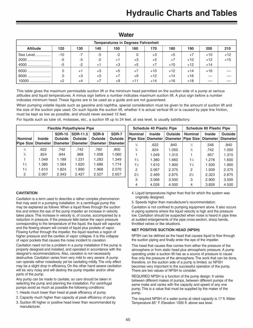
45
Hydraulic Charts and Tables
CAVITATION
Cavitation is a term used to describe a rather complex phenomenonthat may exist in a pumping installation. In a centrifugal pump thismay be explained as follows. When a liquid flows through the suctionline and enters the eye of the pump impeller an increase in velocitytakes place. This increase in velocity is, of course, accompanied by areduction in pressure. If the pressure falls below the vapor pressurecorresponding to the temperature of the liquid, the liquid will vaporizeand the flowing stream will consist of liquid plus pockets of vapor.Flowing further through the impeller, the liquid reaches a region ofhigher pressure and the cavities of vapor collapse. It is this collapseof vapor pockets that causes the noise incident to caviation.Cavitation need not be a problem in a pump installation if the pump isproperly designed and installed, and operated in accordance with thedesigner’s recommendations. Also, caviation is not necessarilydestructive. Cavitation varies from very mild to very severe. A pumpcan operate rather noiselessly yet be cavitating mildly. The only effectmay be a slight drop in efficiency. On the other hand severe cavitationwill be very noisy and will destroy the pump impeller and/or otherparts of the pump.Any pump can be made to cavitate, so care should be taken inselecting the pump and planning the installation. For centrifugalpumps avoid as much as possible the following conditions:1. Heads much lower than head at peak efficiency of pump.2. Capacity much higher than capacity at peak efficiency of pump.3. Suction lift higher or positive head lower than recommended by
manufacturer.
4. Liquid temperatures higher than that for which the system wasoriginally designed.
5. Speeds higher than manufacturer’s recommendation.Cavitation is not confined to pumping equipment alone. It also occursin piping systems where the liquid velocity is high and the pressurelow. Cavitation should be suspected when noise is heard in pipe linesat sudded enlargements of the pipe cross-section, sharp bends,throttled valves or like situations.
NET POSITIVE SUCTION HEAD (NPSH)
NPSH can be defined as the head that causes liquid to flow throughthe suction piping and finally enter the eye of the impeller.
This head that causes flow comes from either the pressure of theatmosphere or from static head plus atmospheric pressure. A pumpoperating under a suction lift has as a source of pressure to causeflow only the pressure of the atmosphere. The work that can be done,therefore, on the suction side of a pump is limited, so NPSHbecomes very important to the successful operation of the pump.There are two values of NPSH to consider.
REQUIRED NPSH is a function of the pump design. It variesbetween different makes of pumps, between different pumps of thesame make and varies with the capacity and speed of any onepump. This is a value that must be supplied by the maker of thepump.
The required NPSH of a water pump at rated capacity is 17 ft. WaterTemperature 85° F. Elevation 1000 ft. above sea level.
Flexible Polyethylene Pipe
SDR-15 SDR-11.5 SDR-9 SDR-7Nominal Inside Outside Outside Outside OutsidePipe Size Diameter Diameter Diameter Diameter Diameter
1⁄2 .622 .742 .742 .760 .8003⁄4 .824 .944 .968 1.008 1.0601 1.049 1.189 1.231 1.283 1.349
11⁄4 1.380 1.564 1.620 1.686 1.77411⁄2 1.610 1.824 1.890 1.968 2.0702 2.067 2.343 2.427 2.527 2.657
Schedule 40 Plastic Pipe Schedule 80 Plastic Pipe
Nominal Inside Outside Nominal Inside OutsidePipe Size Diameter Diameter Pipe Size Diameter Diameter
1⁄2 .622 .840 1⁄2 .546 .8403⁄4 .824 1.050 3⁄4 .742 1.0501 1.049 1.315 1 .957 1.315
11⁄4 1.380 1.660 11⁄4 1.278 1.60011⁄2 1.610 1.900 11⁄2 1.500 1.9002 2.067 2.375 2 1.939 2.375
21⁄2 2.469 2.875 21⁄2 2.323 2.8753 3.068 3.500 3 2.900 3.5004 4.026 4.500 4 3.826 4.500
This table gives the maximum permissible suction lift or the minimum head permitted on the suction side of a pump at various altitudes and liquid temperatures. A minus sign before a number indicates maximum suction lift. A plus sign before a number indicates minimum head. These figures are to be used as a guide and are not guaranteed.When pumping volatile liquids such as gasoline and naphtha, special consideration must be given to the amount of suction lift andthe size of the suction pipe used. On such liquids the suction lift, whether it is actual vertical lift or is caused by pipe line friction,must be kept as low as possible, and should never exceed 12 feet.For liquids such as lube oil, molasses, etc., a suction lift up to 24 feet, at sea level, is usually satisfactory.
Temperatures in Degrees Fahrenheit
Altitude 120 130 140 150 160 170 180 190 200 210
Sea Level............... -10 -7 -5 -2 0 +3 +5 +7 +10 +122000 ...................... -5 -5 -2 +1 +3 +5 +7 +10 +12 +154000 ...................... -5 -2 +1 +3 +5 +7 +10 +12 +14
6000 ...................... 0 +1 +3 +5 +7 +10 +12 +14 +16 ––8000 ...................... 0 +3 +5 +7 +9 +12 +14 +16 –– ––10000 .................... +2 +4 +7 +9 +11 +14 +16 +18 –– ––
Water

46
Hydraulic Charts and Tables
Entrance and friction losses in suction piping calculated = 2 ft. Whatwill be the maximum suction lift permissible?
To better visualize the problem the solution is presented graphicallyon the right. The two horizontal lines are spaced apart a distanceequal to the barometric pressure in feet.
AVAILABLE NPSH is a function of the system in which the pumpoperates. It can be calculated for any installation. Any pump installa-tion, to operate successfully, must have an available NPSH equal toor greater than the required NPSH of the pump at the desired pumpconditions.
When the source of liquid is above the pump:
NPSH = Barometric Pressure, ft. + Static Head on suction, ft.-friction losses in suction piping, ft. - Vapor Pressure of liquid, ft.
When the source of liquid is below the pump:
NPSH = Barometric Pressure, ft. - Static Suction lift, ft.-friciton losses in suction piping, ft. - Vapor Pressure of liquid, ft.
To Illustrate the Use of These EquationsConsider the Following Example:
It is possible to approximate water flow from horizontal or verticalpipes when it is not practical to use flow meters or other measuringdevices. This can be done by measuring to the top of the flowing
stream, always measuring the horizontal distance “X” in inches asillustrated, and determining the flow from the chart show below.
12.4’
17.0’
1.4’
2’
Graphic Solution NPSH Problem
Vapor Pressure for 85° F fromTable 23, Sec. IV = 0.6 psi - 1.4 ft.
NPSH Required = 17’Obtain from Pump Manufactuer
Calculate from Hydraulics of thePiping System = 2’
Losses in Suction
Static Suction Lift Permissible32.9’ – (2.0 + 17.0 + 1.4) = 12.5’
Bar
om
etri
c P
ress
ure
in F
t.
at 8
5° F
Wat
er, a
t 10
00 F
t.
==
32.9
Ft.
32.8
0.99
6
APPROXIMATING WATER FLOW
Std. Wt. SteelPipe, Inside Distance X, In., When Y = 12”
Dia., In.
Nominal Actual 12 14 16 18 20 22 24 26 28 30 32
2 2.067 42 49 56 63 70 77 84 91 98 105 11221⁄2 2.469 60 70 80 90 100 110 120 130 140 150 1603 3.068 93 108 123 139 154 169 185 200 216 231 2464 4.026 159 186 212 239 266 292 318 345 372 398 4255 5.067 250 292 334 376 417 459 501 543 585 627 6686 6.065 362 422 482 542 602 662 722 782 842 902 9628 7.981 627 732 837 942 1047 1150 1255 1360 1465 1570 167510 10.020 980 1145 1310 1475 1635 1800 1965 2130 2290 2455 262012 12.000 1415 1650 1890 2125 2360 2595 2830 3065 3300 3540 3775
Approximate Capacity, GPM,for Full Flowing Horizontal Pipes
The accuracy of these methods will vary up to 10%. The pipe must be flowing full.
Nominal Vertical Height, H, of Water Jet, In.
I.D. Pipe, In. 3 3.5 4 4.5 5 5.5 6 7 8 10 12
2 38 41 44 47 50 53 56 61 65 74 823 81 89 96 103 109 114 120 132 141 160 1774 137 151 163 174 185 195 205 222 240 269 2996 318 349 378 405 430 455 480 520 560 635 7008 567 623 684 730 776 821 868 945 1020 1150 127010 950 1055 1115 1200 1280 1350 1415 1530 1640 1840 2010
Approximate Capacity, GPM,for Full Flowing Vertial Pipes

47
Hydraulic Charts and Tables
Figures in Table are in Gallons Per Minute
Length (L) of Weir in Feet Length (L) of Weir in Feet
Additional Additional Head (H) GPM for Head (H) GPM for
in Each Ft. in Each Ft.Inches 1 3 5 Over 5 Ft. Inches 3 5 Over 5 Ft.
1 35.4 107.5 179.8 36.05 8 2338 3956 81411⁄4 49.5 150.4 250.4 50.4 81⁄4 2442 4140 85011⁄2 64.9 197 329.5 66.2 81⁄2 2540 4312 89013⁄4 81 248 415 83.5 83⁄4 2656 4511 929
2 98.5 302 506 102 9 2765 4699 97021⁄4 117 361 605 122 91⁄4 2876 4899 101121⁄2 136.2 422 706 143 91⁄2 2985 5098 105123⁄4 157 485 815 165 93⁄4 3101 5288 1091
3 177.8 552 926 187 10 3216 5490 113631⁄4 199.8 624 1047 211 101⁄2 3480 5940 123031⁄2 222 695 1167 236 11 3716 6355 132033⁄4 245 769 1292 261 111⁄2 3960 6780 1410
4 269 846 1424 288 12 4185 7165 149541⁄4 293.6 925 1559 316 121⁄2 4430 7595 157541⁄2 318 1006 1696 345 13 4660 8010 166043⁄4 344 1091 1835 374 131⁄2 4950 8510 1780
5 370 1175 1985 405 14 5215 8980 188551⁄4 395.5 1262 2130 434 141⁄2 5475 9440 198551⁄2 421.6 1352 2282 465 15 5740 9920 209053⁄4 449 1442 2440 495 151⁄2 6015 10400 2165
6 476.5 1535 2600 528 16 6290 10900 230061⁄4 1632 2760 560 161⁄2 6565 11380 241061⁄2 1742 2920 596 17 6925 11970 252063⁄4 1826 3094 630 171⁄2 7140 12410 2640
7 1928 3260 668 18 7410 12900 274571⁄4 2029 3436 701.5 181⁄2 7695 13410 285571⁄2 2130 3609 736 19 7980 13940 297073⁄4 2238 3785 774 191⁄2 8280 14460 3090
Discharge from Rectangular Weir with End Contractions
This table is based on Francis formula:Q = 3.33 (L – 0.2H)H1.5
whichQ = ft.3 of water flowing per second.L = length of weir opening in feet (should be 4 to 8 times H).H = head on weir in feet (to be measured at least 6 ft. back of weir opening).a = should be at least 3 H.
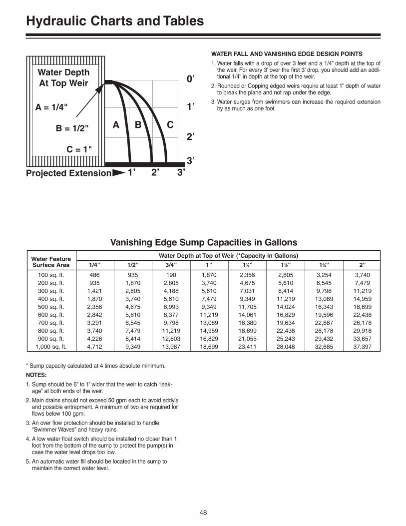
48
Hydraulic Charts and Tables
WATER FALL AND VANISHING EDGE DESIGN POINTS
1. Water falls with a drop of over 3 feet and a 1/4” depth at the top ofthe weir. For every 3’ over the first 3’ drop, you should add an addi-tional 1/4” in depth at the top of the weir.
2. Rounded or Copping edged weirs require at least 1” depth of waterto break the plane and not rap under the edge.
3. Water surges from swimmers can increase the required extensionby as much as one foot.
* Sump capacity calculated at 4 times absolute minimum.
NOTES:
1. Sump should be 6” to 1’ wider that the weir to catch “leak-age” at both ends of the weir.
2. Main drains should not exceed 50 gpm each to avoid eddy’sand possible entrapment. A minimum of two are required forflows below 100 gpm.
3. An over flow protection should be installed to handle“Swimmer Waves” and heavy rains.
4. A low water float switch should be installed no closer than 1foot from the bottom of the sump to protect the pump(s) incase the water level drops too low.
5. An automatic water fill should be located in the sump tomaintain the correct water level.
A B C
0’
1’
1’
2’
2’3’
3’Projected Extension
Water DepthAt Top Weir
A = 1/4"
B = 1/2"
C = 1"
Water Feature Water Depth at Top of Weir (*Capacity in Gallons)
Surface Area 1/4” 1/2” 3/4” 1” 11⁄4” 11⁄2” 13⁄4” 2”
100 sq. ft. 486 935 190 1,870 2,356 2,805 3,254 3,740200 sq. ft. 935 1,870 2,805 3,740 4,675 5,610 6,545 7,479300 sq. ft. 1,421 2,805 4,188 5,610 7,031 8,414 9,798 11,219400 sq. ft. 1,870 3,740 5,610 7,479 9,349 11,219 13,089 14,959500 sq. ft. 2,356 4,675 6,993 9,349 11,705 14,024 16,343 18,699600 sq. ft. 2,842 5,610 8,377 11,219 14,061 16,829 19,596 22,438700 sq. ft. 3,291 6,545 9,798 13,089 16,380 19,634 22,887 26,178800 sq. ft. 3,740 7,479 11,219 14,959 18,699 22,438 26,178 29,918900 sq. ft. 4,226 8,414 12,603 16,829 21,055 25,243 29,432 33,657
1,000 sq. ft. 4,712 9,349 13,987 18,699 23,411 28,048 32,685 37,397
Vanishing Edge Sump Capacities in Gallons

49
Hydraulic Charts and Tables
Units of Volume
Unit U.S. Gallon Imperial Gallon Cubic Feet Pounds of Water Cubic Meters
U.S. Gallon 1.0 .833 .1337 8.33 .003785
Imperial Gallon 1.2 1.0 .1605 10.9 .004546
Cubic Feet 7.481 6.232 1.0 62.37 .0283
Pounds of Water .12 .1 .0160 1.0 .00045
Cubic Meters 264.2 220.0 35.31 2,204.0 1.0
Conversion Tables
Units of Length
Unit Inch Foot Yard Meter
Inch 1.0 .0833 .0278 .0254
Foot 12.0 1.0 .333 .0348
Yard 36.0 3.0 1.0 .9144
Meter 39.37 3.281 1.094 1.0
Units of Area
Unit Inch Foot Yard Meter
Square Inch 1.0 .00694 .000772 .000645
Square Foot 144.0 1.0 .1111 .0929
Square Yard 1,296.0 9.0 1.0 .836
Square Meter 1,550.0 10.76 1.196 1.0
Units of Flow
Unit U.S. GPM Imperial GPM Cubic Feet/Second Cubic Feet/Hour Liters/Second
U.S. GPM 1.0 .833 .00223 .227 .0631
Imperial GPM 1.2 1.0 .00268 .272 .0757
Cubic Feet/Second 448.4 374.0 1.0 101.9 28.32
Cubic Feet/Hour 4.403 3.67 .00981 1.0 .2778
Liters/Second 15.85 13.21 .0353 3.60 1.0
Units of Pressure
Unit Inches of Water Feet of Water Pounds per Square Inch Inches of Mercury
Inches of Water 1.0 .833 .0361 .0736
Feet of Water 12.0 1.0 .433 .883
Pounds per Square Inch 27.72 2.31 1.0 2.04
Inches of Mercury 13.596 1.133 .4906 1.0

50
Hydraulic Charts and Tables
Temperatures in Degrees Fahrenheit
Dimension in Feet 1’ 4’ 5’ 6’ 8’ 10’ 11’ 12’
4 x 4 ....................................... 119.68 479 598 718 957 1197 1316 14365 x 5 ....................................... 187.00 748 935 1202 1516 1870 2057 22446 x 6 ....................................... 269.28 1077 1346 1616 2154 2693 2968 3231
7 x 7 ....................................... 366.52 1466 1833 2199 2922 3665 4032 43988 x 8 ....................................... 478.72 1915 2394 2872 3830 4787 5266 57459 x 9 ....................................... 605.88 2424 3029 3635 4847 6059 6665 7212
10 x 10 ................................... 748.08 2992 3740 4488 5984 7480 8228 897611 x 11 ................................... 905.08 3620 4525 5430 7241 9051 9956 1086112 x 12 ................................... 1077.12 4308 5386 6463 8617 10771 11848 12925
Capacity of Square Tanks
Cylindrical Tanks Set Horizontally and Partially filled
To find the capacity of a depth not given, multiply the capacity for one foot by the required depth in feet.
Gallons per Foot of Length When Tank is Filled
Diameter 1/10 1/5 3/10 2/5 1/2 3/5 7/10 4/5 9/10
1 Ft. ........................... .3 .8 1.4 2.1 2.9 3.6 4.3 4.9 5.52 Ft. ........................... 1.2 3.3 5.9 8.8 11.7 14.7 17.5 20.6 22.23 Ft. ........................... 2.7 7.5 13.6 19.8 26.4 33.0 39.4 45.2 50.14 Ft. ........................... 4.9 13.4 23.8 35.0 47.0 59.0 70.2 80.5 89.05 Ft. ........................... 7.6 20.0 37.0 55.0 73.0 92.0 110.0 126.0 139.0
6 Ft. ........................... 11.0 30.0 53.0 78.0 106.0 133.0 158.0 182.0 201.07 Ft. ........................... 15.0 41.0 73.0 107.0 144.0 181.0 215.0 247.0 272.08 Ft. ........................... 19.0 52.0 96.0 140.0 188.0 235.0 281.0 322.0 356.09 Ft. ........................... 25.0 67.0 112.0 178.0 238.0 298.0 352.0 408.0 450.0
10 Ft. ........................... 30.0 83.0 149.0 219.0 294.0 368.0 440.0 504.0 556.0
11 Ft. ........................... 37.0 101.0 179.0 265.0 356.0 445.0 531.0 610.0 672.012 Ft. ........................... 44.0 120.0 214.0 315.0 423.0 530.0 632.0 741.0 800.013 Ft. ........................... 51.0 141.0 250.0 370.0 496.0 621.0 740.0 850.0 940.014 Ft. ........................... 60.0 164.0 291.0 430.0 576.0 722.0 862.0 989.0 1084.015 Ft. ........................... 68.0 188.0 334.0 494.0 661.0 829.0 988.0 1134.0 1253.0

51
Hydraulic Charts and Tables
1⁄64 .015625 9⁄64 .140625 17⁄64 .265625 25⁄64 .390625 33⁄64 .515625 41⁄64 .640025 49⁄64 .765625 57⁄64 .8906251⁄32 .03125 5⁄32 .15625 9⁄32 .28125 13⁄32 .40625 17⁄32 .53125 21⁄32 .65625 25⁄32 .78125 29⁄32 .906253⁄64 .046875 11⁄64 .171875 19⁄64 .171875 27⁄64 .421875 25⁄64 .546875 43⁄64 .671875 51⁄64 .796875 59⁄64 .9218751⁄16 .0625 3⁄16 .1875 5⁄16 .3125 7⁄16 .4375 9⁄16 .5625 11⁄16 .6875 13⁄16 .8125 15⁄16 .93755⁄64 .078125 13⁄64 .203125 21⁄64 .328125 29⁄64 .453125 37⁄64 .578125 45⁄64 .703125 53⁄64 .828125 61⁄64 .9531253⁄32 .09375 7⁄32 .21875 11⁄32 .34375 15⁄32 .46875 19⁄32 .59375 23⁄32 .71875 27⁄32 .84375 31⁄32 .968757⁄64 .109375 15⁄64 .234375 23⁄64 .359375 31⁄64 .484375 39⁄64 .609375 47⁄64 .734375 55⁄64 .859375 63⁄64 .9843751⁄8 .125 1⁄4 .250 3⁄8 .375 1⁄2 .500 5⁄8 .625 3⁄4 .750 7⁄8 .875 1.000
Decimal Equivalents
Capacity of Round TanksPer Foot of Depth
To find the capacity of tanks greater than shown here, find a tank of one-half the size desired, and multiply its capacity by four, orfind one one-third the size desired and multiply its capacity by 9.
Area Area Area AreaDiam. Gals. Sq. Ft. Diam. Gals. Sq. Ft. Diam. Gals. Sq. Ft. Diam. Gals. Sq. Ft.
1’ 5.87 .785 4’ 94.00 12.566 11’ 710.90 95.03 22’ 2843.60 380.131’ 1” 6.89 .922 4’ 1” 97.96 13.095 11’ 3” 743.58 99.40 22’ 3” 2908.60 388.821’ 2” 8.00 1.069 4’ 2” 102.00 13.635 11’ 6” 776.99 103.87 22’ 6” 2974.30 397.611’ 3” 9.18 1.227 4’ 3” 106.12 14.186 11’ 9” 811.14 108.43 22’ 9” 3040.80 406.491’ 4” 10.44 1.396 4’ 4” 110.32 14.748 12’ 846.03 113.10 23’ 3108.00 415.481’ 5” 11.79 1.576 4’ 5” 114.61 15.321 12’ 3” 881.65 117.86 23’ 3” 3175.90 424.56
1’ 6” 13.22 1.767 4’ 6” 118.97 15.90 12’ 6” 918.00 122.72 23’ 6” 3244.60 433.741’ 7” 14.73 1.969 4’ 7” 123.42 16.50 12’ 9” 955.09 127.68 23’ 9” 3314.00 443.011’ 8” 16.32 2.182 4’ 8” 127.95 17.10 13’ 992.73 132.73 24’ 3384.10 452.391’ 9” 17.99 2.405 4’ 9” 132.56 17.72 13’ 3” 1031.50 137.89 24’ 3” 3455.00 461.861’ 10” 19.75 2.640 4’ 10” 137.25 18.35 13’ 6” 1070.80 142.14 24’ 6” 3526.60 471.441’ 11” 21.58 2.885 4’ 11” 142.02 18.99 13’ 9” 1110.80 148.49 24’ 9” 3598.90 481.11
2’ 23.50 3.142 5’ 8” 188.66 25.22 14’ 1151.50 153.94 25’ 3672.00 490.872’ 1” 25.50 3.409 5’ 9” 194.25 25.97 14’ 3” 1193.00 159.48 25’ 3” 3745.80 500.742’ 2” 27.58 3.687 5’ 10” 199.92 26.73 14’ 6” 1235.30 165.13 25’ 6” 3820.30 510.712’ 3” 29.74 3.976 5’ 11” 205.67 27.49 14’ 9” 1278.20 170.87 25’ 9” 3895.60 527.772’ 4” 31.99 4.276 6’ 211.51 28.27 15’ 1321.90 176.71 26’ 3971.60 530.932’ 5” 34.31 4.587 6’ 3” 229.50 30.68 15’ 3” 1366.40 182.65 26’ 3” 4048.40 541.19
2’ 6” 36.72 4.909 6’ 6” 248.23 35.18 15’ 6” 1411.50 188.69 26’ 6” 4125.90 551.552’ 7” 39.21 5.241 6’ 9” 267.69 35.78 15’ 9” 1457.40 194.83 26’ 9” 4204.10 562.002’ 8” 41.78 5.585 7’ 287.88 38.48 16’ 1504.10 201.06 27’ 4283.00 572.662’ 9” 44.43 5.940 7’ 3” 308.81 41.28 16’ 3” 1551.40 207.39 27’ 3” 4362.70 583.212’ 10” 47.16 6.305 7’ 6” 330.48 44.18 16’ 6” 1599.50 213.82 27’ 6” 4443.10 593.962’ 11” 49.98 6.681 7’ 9” 352.88 47.17 16’ 9” 1648.40 220.35 27’ 9” 4524.30 604.81
3’ 52.88 7.069 8’ 376.01 50.27 19’ 2120.90 283.53 28’ 4606.20 615.753’ 1” 55.86 7.467 8’ 3” 399.80 53.46 19’ 3” 2177.10 291.04 28’ 3” 4688.80 626.803’ 2” 58.92 7.876 8’ 6” 424.48 56.75 19’ 6” 2234.00 298.65 28’ 6” 4772.10 637.943’ 3” 62.06 8.296 8’ 9” 449.82 60.13 19’ 9” 2291.70 306.35 28’ 9” 4856.20 649.183’ 4” 65.28 8.727 9’ 475.89 63.62 20’ 2350.10 314.16 29’ 4941.00 660.523’ 5” 68.58 9.168 9’ 3” 502.70 67.20 20’ 3” 2409.20 322.06 29’ 3” 5026.60 671.96
3’ 6” 71.97 9.621 9’ 6” 530.24 70.88 20’ 6” 2469.10 330.06 29’ 6” 5112.90 683.493’ 7” 75.44 10.085 9’ 9” 558.51 74.66 20’ 9” 2529.60 338.16 29’ 9” 5199.90 695.133’ 8” 78.99 10.559 10’ 587.52 78.54 21’ 2591.00 346.36 30’ 5287.70 706.863’ 9” 82.62 11.045 10’ 3” 617.26 82.52 21’ 3” 2653.00 354.66 30’ 3” 5376.20 718.693’ 10” 86.33 11.541 10’ 6” 640.74 86.59 21’ 6” 2715.80 363.05 30’ 6” 5465.40 730.623’ 11” 90.13 12.048 10’ 9” 678.95 90.76 21’ 9” 2779.30 371.54 30’ 9” 5555.40 742.64

52
Hydraulic Charts and Tables
Diam. Circum. Area Diam. Circum. Area Diam. Circum. Area Diam. Circum. Area Diam. Circum. Area1⁄64 .04909 .000191⁄32 .09818 .000773⁄64 .14726 .001731⁄16 .19635 .003073⁄32 .29452 .006901⁄8 .39270 .01227
5⁄32 .49087 .019173⁄16 .58905 .027617⁄32 .68722 .037581⁄4 .78540 .04909
9⁄32 .88357 .062135⁄16 .98175 .07670
11⁄32 1.0799 .092813⁄8 1.1781 .11045
13⁄32 1.2763 .129627⁄16 1.3744 .15033
15⁄32 1.4726 .172571⁄2 1.5708 .19635
17⁄32 1.6690 .221669⁄16 1.7671 .24850
19⁄32 1.8653 .276885⁄8 1.9635 .30680
21⁄32 2.0617 .3382411⁄16 2.1598 .3712223⁄32 2.2580 .40574
3⁄4 2.3562 .4417925⁄32 2.4544 .4793713⁄16 2.5525 .5184927⁄32 2.6507 .55914
7⁄8 2.7489 .6013229⁄32 2.8471 .6450415⁄16 2.9452 .690331⁄32 3.0434 .73708
1. 3.1416 .78541⁄16 3.3379 .88661⁄8 3.5343 .9940
3⁄18 3.7306 1.10751⁄4 3.9270 1.2272
5⁄16 4.1233 1.35303⁄8 4.3197 1.4849
7⁄16 4.5160 1.62301⁄2 4.7124 1.7671
9⁄16 4.9087 1.91755⁄8 5.1051 2.0739
11⁄16 5.3014 2.23653⁄4 5.4978 2.4053
13⁄16 5.6941 2.58027⁄8 5.8905 2.7612
15⁄16 6.0868 2.94832. 6.2832 3.1416
1⁄16 6.4795 3.34101⁄8 6.6759 3.5466
3⁄16 6.8722 3.75831⁄4 7.0686 3.9761
5⁄16 7.2649 4.20003⁄8 7.4613 4.4301
7⁄16 7.6576 4.66641⁄2 7.8540 4.9087
9⁄16 8.0503 5.15725⁄8 8.2467 5.4119
11⁄16 8.4430 5.67273⁄4 8.6394 5.9396
2. 13⁄16 8.8357 6.21267⁄8 9.0321 6.4918
15⁄16 9.2284 6.77713. 9.4248 7.0686
1⁄16 9.6211 7.36621⁄8 9.8175 7.6699
3⁄16 10.014 7.97981⁄4 10.210 8.2958
5⁄16 10.407 8.61793⁄8 10.603 8.9462
7⁄16 10.799 9.28061⁄2 10.996 9.6211
9⁄16 11.192 9.96785⁄8 11.388 10.321
11⁄16 11.585 10.6803⁄4 11.781 11.045
13⁄16 11.977 11.4167⁄8 12.174 11.793
15⁄16 12.370 12.1774. 12.566 12.566
1⁄16 12.763 12.9621⁄8 12.959 13.364
3⁄16 13.155 13.7721⁄4 13.352 14.186
5⁄16 13.548 14.6073⁄8 13.744 15.033
7⁄16 13.941 15.4661⁄2 14.137 15.904
9⁄16 14.334 16.3495⁄8 14.530 16.800
11⁄16 14.726 17.2573⁄4 14.923 17.721
13⁄16 15.119 18.1907⁄8 15.315 18.665
15⁄16 15.512 19.1475. 15.708 19.635
1⁄16 15.904 20.1291/8 16.101 20.629
3⁄16 16.297 21.1351⁄4 16.493 21.648
5⁄16 16.690 22.1663/8 16.886 22.691
7⁄16 17.082 23.2211⁄2 17.279 23.758
9⁄16 17.475 24.3015⁄8 17.671 24.850
11⁄16 17.868 25.4063⁄4 18.064 25.967
13⁄16 18.261 26.5357⁄8 18.457 27.019
15⁄16 18.653 27.6886. 18.850 28.274
1⁄8 19.242 29.4651⁄4 19.635 30.6803⁄8 20.028 31.9191⁄2 20.420 33.1835⁄8 20.813 34.4723⁄4 21.206 35.7857⁄8 21.598 37.122
7. 21.911 38.4851⁄8 22.384 39.8711⁄4 22.776 41.282
7. 3⁄8 23.169 42.7181⁄2 23.562 44.1795⁄8 23.955 45.6643⁄4 24.347 47.1737⁄8 24.740 48.707
8. 25.133 50.2651⁄8 25.525 51.8491⁄4 25.918 53.4563⁄8 26.311 55.0881⁄2 26.704 56.7455⁄8 27.096 58.4263⁄4 27.489 60.1327⁄8 27.882 61.862
9. 28.274 63.6171⁄8 28.667 65.3971⁄4 29.060 67.2013⁄8 29.452 69.0291⁄2 29.845 70.8825⁄8 30.238 72.7603⁄4 30.631 74.6627⁄8 31.023 76.589
10. 31.416 78.5401⁄8 31.809 80.5161⁄4 32.201 82.5163⁄8 32.594 84.5411⁄2 32.988 86.5905⁄8 33.379 88.6643⁄4 33.772 90.7637⁄8 34.165 92.886
11. 34.558 95.0331⁄8 34.950 97.2051⁄4 35.343 99.4023⁄8 35.736 101.621⁄2 36.128 103.875⁄8 36.521 106.143⁄4 36.914 108.437⁄8 37.306 110.75
12. 37.699 113.101⁄8 38.092 115.471⁄4 38.485 117.863⁄8 38.877 120.281⁄2 39.270 122.725⁄8 39.663 125.193⁄4 40.055 127.687⁄8 40.448 130.19
13. 40.841 132.731⁄8 41.233 135.301⁄4 41.626 137.893⁄8 42.019 140.501⁄2 42.412 143.145⁄8 42.804 145.803⁄4 43.197 148.497⁄8 43.590 151.20
14. 43.982 153.941⁄8 44.375 156.701⁄4 44.768 159.483⁄8 45.160 162.301⁄2 45.553 165.135⁄8 45.946 167.993⁄4 46.339 170.877⁄8 46.731 173.78
15. 47.124 176.711⁄8 47.517 179.671⁄4 47.909 182.653⁄8 48.302 185.661⁄2 48.695 188.695⁄8 49.087 191.753⁄4 49.480 194.837⁄8 49.873 197.93
16. 50.266 201.061⁄8 50.658 204.221⁄4 51.051 207.393⁄8 51.444 210.601⁄2 51.836 213.825⁄8 52.229 217.083⁄4 52.622 220.357⁄8 53.014 223.65
17. 53.407 226.981⁄8 53.800 230.331⁄4 54.193 233.713⁄8 54.585 237.101⁄2 54.978 240.535⁄8 55.371 243.983⁄4 55.763 247.457⁄8 56.156 250.95
18. 56.549 254.471⁄8 56.941 258.021⁄4 57.334 261.593⁄8 57.727 265.181⁄2 58.120 268.805⁄8 58.512 272.453⁄4 58.905 276.127⁄8 59.298 279.01
19. 59.690 283.531⁄8 60.083 287.271⁄4 60.476 291.043⁄8 60.868 294.831⁄2 61.261 298.655⁄8 61.654 302.493⁄4 62.047 306.357⁄8 62.439 310.24
20. 62.832 314.161⁄8 63.225 318.101⁄4 63.617 322.063⁄8 64.010 326.051⁄2 64.403 330.065⁄8 64.795 334.103⁄4 65.188 338.167⁄8 65.581 342.25
21. 65.973 346.361⁄8 66.366 350.501⁄4 66.759 354.663⁄8 67.152 358.841⁄2 67.544 363.055⁄8 67.937 367.283⁄4 68.330 371.547⁄8 68.722 375.83
22. 69.115 380.151⁄8 69.508 384.461⁄4 69.900 388.823⁄8 70.293 393.20
22. 1⁄2 70.686 397.615⁄8 71.079 402.043⁄4 71.471 406.497⁄8 71.864 410.97
23. 72.257 415.481⁄8 72.649 420.001⁄4 73.042 424.563⁄8 73.435 429.131⁄2 73.827 433.745⁄8 74.220 438.363⁄4 74.613 443.017⁄8 75.006 447.69
24. 75.398 452.391⁄8 75.791 457.111⁄4 76.184 461.863⁄8 76.576 466.641⁄2 76.969 471.445⁄8 77.362 476.263⁄4 77.754 481.117⁄8 78.147 485.98
25. 78.540 490.871⁄8 78.933 495.791⁄4 79.325 500.743⁄8 79.718 505.711⁄2 80.111 510.715⁄8 80.503 515.723⁄4 80.896 520.777⁄8 81.289 525.84
26. 81.681 530.931⁄8 82.074 536.051⁄4 82.467 541.193⁄8 82.860 546.351⁄2 83.252 551.555⁄8 83.645 556.763⁄4 84.038 562.007⁄8 84.430 567.27
27. 84.823 572.561⁄8 85.216 557.871⁄4 85.608 583.213⁄8 86.001 588.571⁄2 86.394 593.965⁄8 86.787 599.373⁄4 87.179 604.817⁄8 87.572 610.27
28. 87.965 615.751⁄8 88.357 621.261⁄4 88.750 626.803⁄8 89.143 632.361⁄2 89.535 637.945⁄8 89.928 643.553⁄4 90.321 649.187⁄8 90.714 654.84
29. 91.106 660.521⁄8 91.499 666.231⁄4 91.892 671.963⁄8 92.284 677.711⁄4 92.677 683.495⁄8 93.070 689.303⁄4 93.462 695.13
30. 94.248 706.86
Circumferences and Areas of CirclesDiameter from 1/64 to 30, Advancing Chiefly by Eighths

53
Hydraulic Charts and Tables
The viscosity is often expressed in terms of vis-cosimeters other than the Saybolt Universal. The formulas for the various viscosimeters are as follows:
absolute viscosityKinematic viscosity equals
specific gravity
188Redwood K = .26 t –
t(British)
40.3Redwood Admiralty K = 2.39 6 –
t(British)
180Saybolt Universal K = .22 t –
t(American)
203Saybolt Furol K = 2.2 t –
t(American)
374Engler K = 1.47 t –
t(German)
t = Engler Degrees x 51.3
If viscosity is given at any two temperatures, the viscosity at any other temperature can be obtain byplotting the viscosity against temperature in degreesFahrenheit on special log paper. The points for agiven oil lie in a straight line.
KinematicViscosity Seconds Seconds Seconds
Centistokes Saybolt Saybolt Seconds Redwood Degrees Degrees=K Universal Furol Redwood Admiralty Engler Barbey
1.00 31 –– 29. –– 1.00 62002.56 35 –– 32.1 –– 1.16 24204.30 40 –– 36.2 5.10 1.31 14405.90 45 –– 40.3 5.52 1.46 10507.40 50 –– 44.3 5.83 1.58 838
8.83 55 –– 48.5 6.35 1.73 70210.20 60 –– 52.3 6.77 1.88 61811.53 65 –– 56.7 7.17 2.03 53812.83 70 12.95 60.9 7.60 2.17 48314.10 75 13.33 65.0 8.00 2.31 440
15.35 80 13.70 69.2 8.44 2.45 40416.58 85 14.10 73.3 8.86 2.59 37417.80 90 14.44 77.6 9.30 2.73 34819.00 95 14.85 81.5 9.70 2.88 32620.20 100 15.24 85.6 10.12 3.02 307
31.80 150 19.3 128 14.48 4.48 19543.10 200 23.5 170 18.90 5.92 14454.30 250 28.0 212 23.45 7.35 11465.40 300 32.5 254 28.0 8.79 9576.50 350 35.1 296 32.5 10.25 81
87.60 400 41.9 338 37.1 11.70 70.898.60 450 46.8 381 41.7 13.15 62.9
110 500 51.6 423 46.2 14.60 56.4121 550 56.6 465 50.8 16.05 51.3132 600 61.4 508 55.4 17.50 47.0
143 650 66.2 550 60.1 19.00 43.4154 700 71.1 592 64.6 20.45 40.3165 750 76.0 635 69.2 21.90 37.6176 800 81.0 677 73.8 23.35 35.2187 850 86.0 719 78.4 24.80 33.2
198 900 91.0 762 83.0 26.30 31.3209 950 95.8 804 87.6 27.70 29.7220 1000 100.7 846 92.2 29.20 28.2330 1500 150 1270 138.2 43.80 18.7440 2000 200 1690 184.2 58.40 14.1
550 2500 250 2120 230 73.00 11.3660 3000 300 2540 276 87.60 9.4770 3500 350 2960 322 100.20 8.05880 4000 400 3380 368 117.00 7.05990 4500 450 3810 414 131.50 6.26
1100 5000 500 4230 461 146.00 5.641210 5500 550 4650 507 160.50 5.131320 6000 600 5080 553 175.00 4.701430 6500 650 5500 559 190.00 4.341540 7000 700 5920 645 204.50 4.03
1650 7500 750 6350 691 219.00 3.761760 8000 800 6770 737 233.50 3.521870 8500 850 7190 783 248.00 3.321980 9000 900 7620 829 263.00 3.132090 9500 950 8040 875 277.00 2.972200 10000 1000 8460 921 292.00 2.82
Viscosity Conversion Table

54
Hydraulic Charts and Tables
Gardner-Holt Viscosity Gardner-Holt ViscosityTube Designation SSU Centistokes Tube Designation SSU Centistokes
A 230 50 Q 1977 435B 298 65 R 2136 470C 388 85 S 2273 500D 456 100 T 2500 550
E 568 125 U 2850 627F 636 140 V 4018 884G 750 165 W 4864 1070H 909 200 X 5864 1290
I 1023 225 Y 8000 1760J 1316 250 Z 10318 2270K 1250 275 Z1 12273 2700L 1364 300 Z2 16455 3620
M 1455 320 Z3 21045 4630N 1545 340 Z4 28818 6340O 1682 370 Z5 44773 9850P 1818 400 Z6 67273 14800
Viscosity Conversion TableGardner-Holt Bubble Viscometer to Saybolt Seconds Universal
Absolute KinematicTemp. Viscosity Viscosity
° F Centipoises Centistokes SSU Ft2/Sec
32 1.79 1.79 33.0 0.0000193150 1.31 1.31 31.6 0.0000141060 1.12 1.12 31.2 0.0000121770 0.98 0.98 30.9 0.0000105980 0.86 0.86 30.6 0.0000093085 0.81 0.81 30.4 0.00000869
100 0.68 0.69 30.2 0.00000739120 0.56 0.57 30.0 0.00000609140 0.47 0.48 29.7 0.00000514160 0.40 0.41 29.6 0.00000442180 0.35 0.36 29.5 0.00000385212 0.28 0.29 29.3 0.00000319
Viscosity of Water
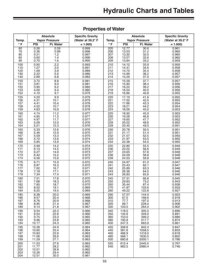
55
Hydraulic Charts and Tables
Absolute Specific Gravity Absolute Specific GravityTemp. Vapor Pressure (Water at 39.2° F Temp. Vapor Pressure (Water at 39.2° F
° F PSI Ft. Water = 1.000) ° F PSI Ft. Water = 1.000)60 0.26 0.59 0.999 205 12.77 30.6 0.96170 0.36 0.89 0.998 206 13.03 31.2 0.96080 0.51 1.2 0.997 207 13.30 32.0 0.96085 0.60 1.4 0.996 208 13.57 32.6 0.96090 0.70 1.6 0.995 209 13.84 33.2 0.959100 0.95 2.2 0.993 210 14.12 33.9 0.959110 1.27 3.0 0.991 211 14.41 34.6 0.958120 1.69 3.9 0.989 212 14.70 35.4 0.958130 2.22 5.0 0.986 213 14.99 36.2 0.957140 2.89 6.8 0.983 214 15.29 37.0 0.957150 3.72 8.8 0.981 215 15.59 37.7 0.957151 3.81 9.0 0.981 216 15.90 38.4 0.956152 3.90 9.2 0.980 217 16.22 39.2 0.956153 4.00 9.4 0.980 218 16.54 40.0 0.956154 4.10 9.7 0.979 219 16.86 40.8 0.955155 4.20 9.9 0.979 220 17.19 41.6 0.955156 4.31 10.1 0.979 221 17.52 42.5 0.955157 4.41 10.4 0.978 222 17.86 43.3 0.954158 4.52 10.7 0.978 223 18.21 44.2 0.954159 4.63 10.9 0.978 224 18.56 45.0 0.953160 4.74 11.2 0.977 225 18.92 45.9 0.953161 4.85 11.5 0.977 226 19.28 46.8 0.953162 4.97 11.7 0.977 227 19.65 47.7 0.952163 5.09 12.0 0.976 228 20.02 48.6 0.952164 5.21 12.3 0.976 229 20.40 49.5 0.951165 5.33 12.6 0.976 230 20.78 50.5 0.951166 5.46 12.9 0.975 231 21.17 51.4 0.951167 5.59 13.3 0.975 232 21.57 52.5 0.950168 5.72 13.6 0.974 233 21.97 53.5 0.950169 5.85 13.9 0.974 234 22.38 54.5 0.950170 5.99 14.2 0.974 235 22.80 55.5 0.949171 6.13 14.5 0.973 236 23.22 56.6 0.949172 6.27 14.9 0.973 237 23.65 57.8 0.948173 6.42 15.2 0.973 238 24.09 58.8 0.948174 6.56 15.6 0.972 239 24.53 59.8 0.948175 6.71 15.9 0.972 240 24.97 61.0 0.947176 6.87 16.3 0.972 241 25.43 62.1 0.947177 7.02 16.7 0.971 242 25.89 63.3 0.946178 7.18 17.1 0.971 243 26.36 64.5 0.946179 7.34 17.4 0.971 244 26.83 65.6 0.946180 7.51 17.8 0.970 245 27.31 66.8 0.945181 7.68 18.3 0.970 250 29.83 73.2 0.943182 7.85 18.7 0.970 260 35.44 87.4 0.938183 8.02 19.1 0.969 270 41.87 103.6 0.933184 8.20 19.5 0.969 280 49.22 122.8 0.927185 8.38 20.0 0.969 290 57.57 144.0 0.923186 8.57 20.4 0.968 300 67.0 168.6 0.918187 8.76 20.9 0.968 310 77.7 197.0 0.913188 8.95 21.4 0.967 320 89.7 228.4 0.908189 9.14 21.8 0.967 330 103.0 264.0 0.902190 9.34 22.3 0.966 340 118.0 305.0 0.896191 9.54 22.8 0.966 350 134.6 349.0 0.891192 9.75 23.3 0.965 360 153.0 399.2 0.886193 9.96 23.8 0.965 380 195.8 517.7 0.874194 10.17 24.3 0.965 400 247.3 663.9 0.861195 10.38 24.9 0.964 420 308.8 842.4 0.847196 10.60 25.4 0.964 440 381.6 1058.5 0.833197 10.83 25.9 0.963 460 466.9 1318.0 0.818198 11.06 26.6 0.963 480 566.1 1630.5 0.802199 11.29 27.1 0.963 500 680.8 2000.1 0.786200 11.53 27.6 0.963 520 812.4 2445.5 0.767201 11.77 28.2 0.962 540 962.5 2980.4 0.746202 12.01 28.8 0.962203 12.26 29.4 0.962204 12.51 30.0 0.961
Properties of Water
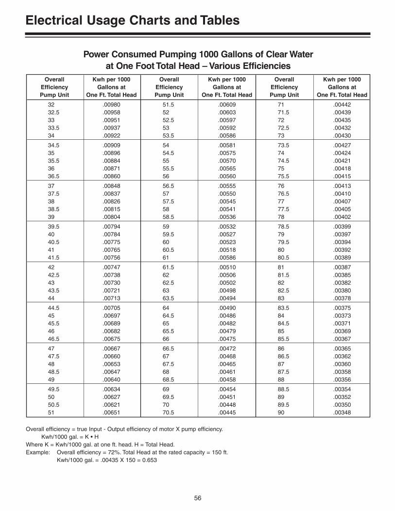
56
Electrical Usage Charts and Tables
Overall Kwh per 1000 Overall Kwh per 1000 Overall Kwh per 1000Efficiency Gallons at Efficiency Gallons at Efficiency Gallons atPump Unit One Ft. Total Head Pump Unit One Ft. Total Head Pump Unit One Ft. Total Head
32 .00980 51.5 .00609 71 .0044232.5 .00958 52 .00603 71.5 .0043933 .00951 52.5 .00597 72 .0043533.5 .00937 53 .00592 72.5 .0043234 .00922 53.5 .00586 73 .00430
34.5 .00909 54 .00581 73.5 .0042735 .00896 54.5 .00575 74 .0042435.5 .00884 55 .00570 74.5 .0042136 .00871 55.5 .00565 75 .0041836.5 .00860 56 .00560 75.5 .00415
37 .00848 56.5 .00555 76 .0041337.5 .00837 57 .00550 76.5 .0041038 .00826 57.5 .00545 77 .0040738.5 .00815 58 .00541 77.5 .0040539 .00804 58.5 .00536 78 .00402
39.5 .00794 59 .00532 78.5 .0039940 .00784 59.5 .00527 79 .0039740.5 .00775 60 .00523 79.5 .0039441 .00765 60.5 .00518 80 .0039241.5 .00756 61 .00586 80.5 .00389
42 .00747 61.5 .00510 81 .0038742.5 .00738 62 .00506 81.5 .0038543 .00730 62.5 .00502 82 .0038243.5 .00721 63 .00498 82.5 .0038044 .00713 63.5 .00494 83 .00378
44.5 .00705 64 .00490 83.5 .0037545 .00697 64.5 .00486 84 .0037345.5 .00689 65 .00482 84.5 .0037146 .00682 65.5 .00479 85 .0036946.5 .00675 66 .00475 85.5 .00367
47 .00667 66.5 .00472 86 .0036547.5 .00660 67 .00468 86.5 .0036248 .00653 67.5 .00465 87 .0036048.5 .00647 68 .00461 87.5 .0035849 .00640 68.5 .00458 88 .00356
49.5 .00634 69 .00454 88.5 .0035450 .00627 69.5 .00451 89 .0035250.5 .00621 70 .00448 89.5 .0035051 .00651 70.5 .00445 90 .00348
Power Consumed Pumping 1000 Gallons of Clear Waterat One Foot Total Head – Various Efficiencies
Overall efficiency = true Input - Output efficiency of motor X pump efficiency.Kwh/1000 gal. = K • H
Where K = Kwh/1000 gal. at one ft. head. H = Total Head.Example: Overall efficiency = 72%. Total Head at the rated capacity = 150 ft.
Kwh/1000 gal. = .00435 X 150 = 0.653
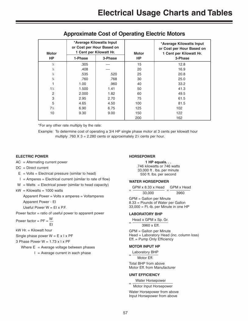
57
Electrical Usage Charts and Tables
ELECTRIC POWER
AC = Alternating current power
DC = Direct current
E = Volts = Electrical pressure (similar to head)
I = Amperes = Electrical current (similar to rate of flow)
W = Watts = Electrical power (similar to head capacity)
kW = Kilowatts = 1000 watts
Apparent Power = Volts x amperes = Voltamperes
Apparent Power - EI
Useful Power W = EI x P.F.
Power factor = ratio of useful power to apparent power
Power factor = PF = W
EI
kW Hr. = Kilowatt hour
Single phase power W = E x I x PF
3 Phase Power W = 1.73 x I x PF
Where E = Average voltage between phases
I = Average current in each phase
HORSEPOWER
1 HP equals. . ..746 kilowatts or 746 watts33,000 ft . lbs. per minute
550 ft. lbs. per second
WATER HORSEPOWER
=GPM x 8.33 x Head
=GPM x Head
33,000 3960
GPM = Gallon per Minute8.33 = Pounds of Water per Gallon33,000 = Ft.-lb. per Minute in one HP
LABORATORY BHP
=Head x GPM x Sp. Gr.
3960 x Eff.
GPM = Gallon per MinuteHead = Laboratory Head (inc. column loss)Eff. = Pump Only Efficiency
MOTOR INPUT HP
=Laboratory BHP
Motor Eff.
Total BHP from aboveMotor Eff. from Manufacturer
UNIT EFFICIENCY
=Water Horsepower
Motor Input Horsepower
Water Horsepower from aboveInput Horsepower from above
*Average Kilowatts Input *Average Kilowatts Inputor Cost per Hour Based on or Cost per Hour Based on
Motor 1 Cent per Kilowatt Hr. Motor 1 Cent per Kilowatt Hr.HP 1-Phase 3-Phase HP 3-Phase
1⁄4 .305 –– 15 12.81⁄3 .408 –– 20 16.91⁄2 .535 .520 25 20.83⁄4 .760 .768 30 25.01 1.00 .960 40 33.2
11⁄2 1.500 1.41 50 41.32 2.000 1.82 60 49.53 2.95 2.70 75 61.55 4.65 4.50 100 81.5
71⁄2 6.90 6.75 125 10210 9.30 9.00 150 122
200 162
Approximate Cost of Operating Electric Motors
*For any other rate multiply by the rate:
Example: To determine cost of operating a 3/4 HP single phase motor at 3 cents per kilowatt hour multiply .760 X 3 = 2.280 cents or approximately 21⁄4 cents per hour.

58
Electrical Usage Charts and Tables
AWG Wire Size
Amps 14 12 10 8 6 4 2 0
2 595 946 14793 397 630 9864 298 470 740 1161 18085 238 378 592 926 14476 198 315 493 774 1206 18427 170 270 423 663 1033 15798 149 236 370 581 904 13819 132 210 329 516 804 1228 187110 119 189 296 464 723 1105 168412 99 158 247 387 603 921 140314 135 211 332 517 789 1203 162216 118 185 290 452 691 1052 142018 164 258 402 614 935 120120 148 232 362 553 842 113622 134 21124 123 194
Single Phase Wire Size Selection Charts
Maximum Distance of Wire Run.
115 Volts – 1 Phase
AWG Wire Size
Amps 14 12 10 8 6 4 2 0
2 1035 16443 690 1096 17154 518 822 12875 414 658 1029 16156 345 548 858 1346 20977 296 470 735 1154 17978 259 411 643 1010 1573 24039 230 365 572 897 1398 213610 207 329 515 808 1258 1922 292812 173 274 429 673 1048 1602 244014 235 368 577 899 1373 2091 282116 206 322 505 786 1201 1830 246918 286 449 699 1068 1627 219420 257 404 629 961 1464 197522 234 367 572 874 1331 179524 214 337 524 801 1220 164626 311 484 739 1126 151928 288 449 686 1046 141130 269 419 641 976 131735 231 359 549 837 112940 315 481 732 98845 280 427 651 87850 252 384 586 79055 349 532 71860 320 488 658
Maximum Distance of Wire Run.
200 Volts – 1 Phase
AWG Wire Size
Amps 14 12 10 8 6 4 2 0
2 1190 18913 794 12614 595 946 14795 476 756 1184 18586 397 630 986 1548 24117 340 540 845 1327 20678 293 473 740 1161 1808 27639 265 420 658 1032 1607 245610 238 376 592 929 1447 2210 336712 198 315 493 774 1206 1842 280614 270 423 663 1033 1579 2405 324516 236 370 581 904 1381 2105 283918 329 516 804 1228 1871 252420 296 464 723 1105 1684 227122 269 422 658 1005 1531 206524 247 387 603 921 1403 189326 357 556 850 1295 174728 332 517 789 1203 162230 310 482 737 1122 151435 265 413 632 962 129840 362 553 842 113645 321 491 748 100950 239 442 673 909
Maximum Distance of Wire Run.
230 Volts – 1 Phase
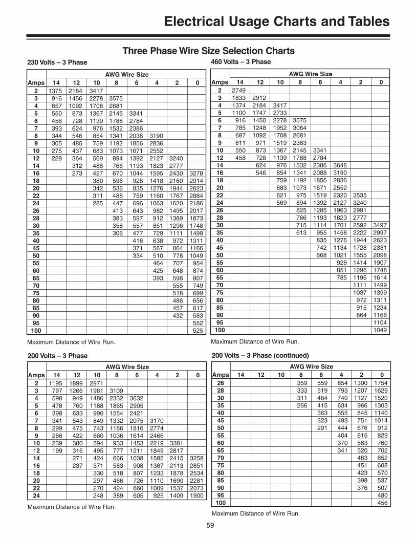
59
Electrical Usage Charts and Tables
Three Phase Wire Size Selection Charts
AWG Wire SizeAmps 14 12 10 8 6 4 2 0
2 1195 1899 29713 797 1266 1981 31094 598 949 1486 2332 36325 478 760 1188 1865 29056 398 633 990 1554 24217 341 543 849 1332 2075 31708 299 475 743 1166 1816 27749 266 422 660 1036 1614 246610 239 380 594 933 1453 2219 338112 199 316 495 777 1211 1849 281714 271 424 666 1038 1585 2415 325816 237 371 583 908 1387 2113 285118 330 518 807 1233 1878 253420 297 466 726 1110 1690 228122 270 424 660 1009 1537 207324 248 389 605 925 1409 1900
Maximum Distance of Wire Run.
200 Volts – 3 Phase
AWG Wire SizeAmps 14 12 10 8 6 4 2 0
26 359 559 854 1300 175428 333 519 793 1207 162930 311 484 740 1127 152035 266 415 634 966 130340 363 555 845 114045 323 493 751 101450 291 444 676 91255 404 615 82960 370 563 76065 341 520 70270 483 65275 451 60880 423 57085 398 53790 376 50795 480100 456
Maximum Distance of Wire Run.
200 Volts – 3 Phase (continued)
AWG Wire SizeAmps 14 12 10 8 6 4 2 0
2 1375 2184 34173 916 1456 2278 35754 657 1092 1708 26815 550 873 1367 2145 33416 458 728 1139 1788 27847 393 624 976 1532 23868 344 546 854 1341 2038 31909 305 485 759 1192 1856 283610 275 437 683 1073 1671 255212 229 364 569 894 1392 2127 324014 312 488 766 1193 1823 277716 273 427 670 1044 1595 2430 327818 380 596 928 1418 2160 291420 342 536 835 1276 1944 262322 311 488 759 1160 1767 288424 285 447 696 1063 1620 218626 413 643 982 1495 201728 383 597 912 1389 187330 358 557 851 1296 174835 306 477 729 1111 149940 418 638 972 131145 371 567 864 116650 334 510 778 104955 464 707 95460 425 648 87465 393 598 80770 555 74975 518 69980 486 65685 457 61790 432 58395 552100 525
Maximum Distance of Wire Run.
230 Volts – 3 Phase
AWG Wire SizeAmps 14 12 10 8 6 4 2 0
2 27493 1833 29124 1374 2184 34175 1100 1747 27336 916 1450 2278 35757 785 1248 1952 30648 687 1092 1708 26819 611 971 1519 238310 550 873 1367 2145 334112 458 728 1139 1788 278414 624 976 1532 2386 364616 546 854 1341 2088 319018 759 1192 1856 283620 683 1073 1671 255222 621 975 1519 2320 353524 569 894 1392 2127 324026 825 1285 1963 299128 766 1193 1823 277730 715 1114 1701 2592 349735 613 955 1458 2222 299740 835 1276 1944 262345 742 1134 1728 233150 668 1021 1555 209855 928 1414 190760 851 1296 174865 785 1196 161470 1111 149975 1037 139980 972 131185 915 123490 864 116695 1104100 1049
Maximum Distance of Wire Run.
460 Volts – 3 Phase

60
Materials
A BASIC UNDERSTANDING OF PLASTIC MATERIALS USEDIN POOL AND SPA EQUIPMENT
The extensive use of many types of plastic materials in the pool andspa business requires us to have a basic knowledge of what thematerials are, their strengths and limitations, and how to connect orbond the various materials together. This will not be a technical pre-sentation on plastic materials, but a very practical one intended tohelp you to work with plastic components with a greater degree ofunderstanding.
MATERIALS
Here are some commonly used plastic materials found in pool/spacomponents.
CHARACTERISTICS SUMMARY
Trade or Technical Strengths/ Limitations/ TypicalCommon Name Name Advantages Weaknesses Applications
ABS Acrylonitrile-Butadiene-Styrene High impact, molds Stress cracks, Skimmers, valves, mainwell, bonds well. heat sensitive. drains, fittings, filter
internals, filter tanks.
CPVC Chlorinated Polyvinyl Chloride Good heat resistance, High cost, difficult Pipe and fittings foreasily bonded, strong. to mold. hot water applications.
Lexan Polycarbonate High strength, very Low chemical resistance, Trap lids, sight glasses,clear, heat resistant low UV resistance impellers.
(some grades).
Noryl Modified PPO High strength, bondable, Difficulty in molding, Pump bodies, impellers,(polyphenylene oxide) moderate chemical high cost, difficult traps.
resistant. to bond.
Polyethylene Polyethylene Flexible, high impact, High creep, low strength, Filter tanks, flex pipe,low UV resistance, low heat resistance. solar collectors.cost effective. Cannot be glued.
Polypro Polypropylene Good heat & chemical Moderate creep, low D.E. grid cloth, resistance, good UV resistance in separation tank bags, strength. natural color. pump bodies and traps.
Polyester Polyester High strength and Difficult to glue bond, Cartridge filter, chemical resistance, difficult to mold. media cloth.high heat resistance.
PVC Polyvinyl Chloride Flexible, low cost, Moderate heat resistance, Pipe, pipe unions, pool good bonding. low UV resistance, fittings, elbows and
moderate impact resistance. tees, etc.
Styrene Polystyrene Molds well, low cost, Moderate strength, low D.E. grids, trap baskets.bonds well. UV resistance, low
heat resistance.
Vinyl Vinyl Flexible, chemical and Low strength, high creep. Pool liners, solarUV resistant, good for Bonded thermally only. collectors, gaskets.thin sheeting.
61
Materials
This brief summary chart of plastic materials does not take into con-sideration varying grades or blends of material within each generalcompound name. For instance, polyethylene may be used in high,medium or low density grades, each having different strengths andapplications. ABS is a blend of three different polymers or plasticcompounds, and the ratio of each will determine the characteristics ofthe material. This is why the term “engineering grade materials” isoften used to signify that much fine-tuning goes into a plastic com-pound to give the desired performance in a specific application.Varying amounds of fiberglass mixed into the plastic resin canchange or improve the properties of some plastic materials.
ENVIRONMENTAL FACTORS ON PLASTICS
While one of the principal benefits of plastics in the pool/spa environ-ment, is corrosion resistance, there are a number of other factorswhich can harm plastic materials.
1. Sunlight/ultraviolet degradationUltraviolet light (sunlight), can over a period of time, cause plasticsto become brittle, fade in color, and lose much of their physicalstrength. Manufacturers of resins can add compounds to the plas-tic formulas which inhibit the degrading effects of ultraviolet light.The most common and effective UV inhibitor is carbon black. Thisis why most pool pumps and other key pool components are col-ored black. In PVC, vinyl and ABS materials, other chemical UVinhibitors are added which do not change the resin color.
2. HeatThermoplastics common to the pool/spa industry are all sensitiveto temperatures to some extent. This can come from solar heat (orambient air temperature) or from the heat of the water. Somematerials like Noryl and polypropylene have very good heat resis-tance, in excess of boiling water (212°F), before they begin to losestrength. Others like polyethylene, ABS and PVC begin to soften attemperatures only slightly above spa temperatures (110° - 125°F).PVC piping for hot water can be specially formulated for this appli-cation, and is known as CPVC.
3. PressureThe affects of pressure on plastic becomes more critical the largerthe pressure vessel (such as filter tanks) and with increased temz-erature. This is known as creep/rupture tendency. When a plasticpart begins to move, stretch, or distort under pressure and/or heat,it is described as “creep”. Each material has creep tendencieswhich can be measured and often controlled, as with the additionof chopped fiberglass to the resin compound. The materials withthe greatest creep tendencies would be vinyl, polyethylene andPVC, which do not work well with glass reinforcement. If a plasticvessel containing pressure were to creep to its limits of strength, itwould rupture or crack. In the pool/spa environment, because UV,heat and pressure are all powerful environmental factors, designengineers must be concerned with the creep/rupture properties ofeach material when selecting one for a specific plastic component.
INSTALLATION OF EQUIPMENT MADE OF PLASTICS
A.Equipment Selection and ApplicationEach piece of equipment, containing plastic parts or made entirelyof plastic, has been designed for a specific purpose in the pool/spaenvironment. When products are installed in ways that are outsidetheir intended usage, chances of product failure are significantlyincreased. When the proper application of equipment is in ques-tion, contact the manufacturer before making any installation.
B.Pipe ConnectionsThere are two basic ways provided for attachment of piping topool/spa equipment:
1. Threaded Piping ConnectionsNational Pipe Thread (NPT) standards are used throughoutthe USA, which are tapered male and female connectionswith specific threaded pitch and diameters. BSP (BritishStandard Pipe) and DIN (Germany) standards apply in mostforeign markets, and are not compatible with NPT. Because ofthe tapered design of NPT, engagement or overtightening ofpipes in female ports of plastic equipment can result incracked pipe ports, or threaded bosses, if they have not beenproperly designed or molded. Care should be taken to notovertighten threaded pipe nipples beyond the intended 3-4thread engagement.
Use of thread sealant is normally required on pressure or vacu-um connections on piping. The correct choice of thread sealantis critical on plastic components. The plumbing trades have tra-ditionally used “pipe dope” for thread sealant on metal pipesand equipment. However, pipe dope and most teflon pastesealants have a vehicle or base material that is a petroleumproduct. Petroleum compounds will attack many platics used inpool/spa equipment and especially ABS, which is common inskimmers, valves and pool wall fittings, etc. The problem iscalled “stress cracking”. When a pipe is tightened into thefemale port of a component, the port is placed under mechani-cal stress. In this condition, petroleum-based sealants willattack the weakest part of the thread boss and quickly cause itto crack through and leak. Don’t be fooled by claims on thesealant can like “safe for plastics”. This usually means safe forPVC pipe, which is fairly resistant to petroleum sealants. Hereis a list of thread sealants which we know have been reliableand safe for all plastic compounds:Teflon TapePlasto-Joint Stick (Lake Chemical Co.)Permatex #2 (Loctite Mfg. Co.)Silicon RTV: (Room Temperature Vulcanizing)
a: General Electric RTV 60b: Dow Corning Silastic 731, 732 and 738c: Loctite Silicone (same as Dow 732)
It is also recommended that when connecting PVC pipe tocomponents which generate heat, such as pumps or heaters,that CPVC pipe nipples be used for direct connection. There isless chance of material distortion and/or leaks to develop.
2. Solvent WeldingSolvent welding involves the gluing or chemical bonding ofplastic pipe and components. The connection between malepipe and female socket is a slip fit, with the cement having sol-vents to soften and fuse the two parts together, and to fill anyvoids for a leak-free connection. The following are proceduresfor making secure solvent welded connections in a variety ofcombinations of plastic materials.
A. To consistently make good joints the following should beclearly followed:
1. The joining surfaces must be softened and made semi-fluid.
2. Sufficient cement must be applied to fill the gap betweenthe plastic components being assembled.
3. Assembly of components must be made while the sur-faces are still wet and fluid.

62
Materials
4. Joint strength develops as the cement dries. In the tightpart of the joint, the surfaces will tend to fuse together, inthe loose part, the cement will bond to both surfaces. Insome cases clamp or hand pressure must be applied toobtain maximum strength joints. When assembling pipe,follow pipe preparation instructions and dimensionalchecks found on solvent cement containers. Areas ofpipe and fittings to be softened and penetrated (asshown in Figure 2).
Penetration and softening can be achieved by the cement itself. Incold weather more time and additional applications are required.
More than sufficient cement to fill the loose part of the joint must beapplied. Besides filling the gap, adequate cement layers will pene-trate the surfaces and also remain wet until the joint is assembled.
If the cement coatings on the pipe and fittings are wet and fluid whenassembly takes place, they will tend to flow together and becomeone cement layer. Also, if the cement is wet the surfaces beneaththem will still be soft, and these softened surfaces in the tight part ofthe joint will tend to fuse together. If possible, rotate the pipe 1/4 turnafter it is inserted into the female socket.
Hardening of the adhesive (Figure 5).
As the solvent dissipates, the cement layer and the softened surfaceswill harden with a corresponding increase in joint strength. A goodjoint will take the required working pressure long before the joint isfully dry and final strength is obtained. In the tight (fused) part of thejoint, strength will develop more quickly than in the looser (bonded)part of the joint. (It may in some cases be required to hold or fixturethe joint for a short period of time to maintain its proper position).
B. The solvent welding of plastics and recommended solvents.The following are combinations of plastics normally encoun-tered and the recommended solvents for bonding the mate-rials. The solvents are listed in order of preference.
1. Cycolac (Brand ABS) to Cycolac (Brand ABS).
Weld-On #1707 or #771 – a milky clear, semi-viscous,medium bodied, fast set cement normally applied bybrush. Application temperatures – 40°F to 110°F.
Weld-On #1591 or #773 – A black, semi-viscous, medi-um bodied, fast set cement normally applied by brush.Application temeratures – 40°F to 110°F.
MEK (Methyl Ethyl Ketone) Weld-On #2354 – A waterysolvent normally applied by dipping.
2. Cycolac (Brand ABS) to Rigid PVC.
Weld-On #793 – A clear, semi-viscous, light bodied, veryfast set cement normally applied by brush. Applicationtemperatures – 40°F to 110°F. (Not recommended forCycolac (ABS) to Cycolac (ABS) or PVC to 11z+’11zPVC).
Weld-On #794 – A green colored, medium bodied, fastsetting high strength cement. Application temperatures –40°F to 110°F. (Not recommended for cycolac ABS) toCycolac (ABS) or PVC to PVC).
3. Rigid PVC to Rigid PVC (Use P-70 primer or PVC com-ponents only).
Weld-On #711 – A gray, semi-viscous, heavy bodied,fast set, high strength cement normally applied by brush.Excellent for poorly fitting joints. Application temperatures– 40°F to 110°F.
Weld-On #717 – A gray, heavy bodied, medium setadhesive preferred in very humid weather.
Figure 2
Figure 5
Figure 3
Figure 4
These areas must be softened and penetrated(pipe and fitting shown).
Apply cement coatings of sufficient thickness.
Wipe off excess cement immediatelyso the pipe is not weakened.
Bonded Surfaces
Fused Surfaces
63
Materials
4. Cycolac (ABS) to Lexan (polycarbonate).
Methylene Chloride – Mixed with Lexan pellets to pro-vide a semi-viscous solvent to insure voidless joints ofpoorly fitting parts. The solvent is mixed in a ratio of 4parts solvent, by weight, to 1 part Lexan pellets, byweight.
Weld-On #16 – A thick bodied solvent cement availablein tubes and used when part fit is poor.
5. Lexan to PVC (Use P-70 primer on PVC componentonly).
THF (Tetrahydrofurane) Weld-On #2010 – A waterysolvent nromally applied by dipping.
Methylene Chloride – Mixed with Lexan pellets to pro-vide a semi-viscous solvent to insure voidless joints ofpoorly fitting parts. The solvent is mixed in a ration of 4parts solvent, by weight, to 1 part Lexan pellets, byweight.
Weld-On #16 – A thick bodied solvent cement availablein tubes and used when part fit is poor.
6. Styrene to PVC (Use P-70 primer on PVC componentonly).
Weld-On #792 or #1802 – A clear, semi-viscous, medi-um bodied cement normally applied by brush.Application temperatures – 40°F to 110°F.
7. Noryl to PVC (Use P-70 primer on PVC componentonly).
Weld-On #792 or #1802 – A clear, semi-viscous, medi-um bodied cement normally applied by brush.Application temperatures – 40°F to 110°F.
8. Styrene to Cycolac (ABS).
Weld-On #792 or #1802 – A clear, semi-viscous, medi-um bodied cement normally applied by brush.Application temperatures – 40°F to 110°F.
C. Connecting ABS skimmer socket ports to PVC pipe –The following pertains to the bond strength by solvent weld-ing of PVC pipe to the ABS skimmer socket parts.
The recommended solvent for bonding PVC to the ABSskimmer ports is Weld-On #793.
Weld-On P-70 primer should be applied to the PVC pipeonly prior to applying the #793 solvent to both parts at timeof assembly and sufficient drying time is a must to preventcreep and eventual failure of the assembly.
Apply Industrial Polychemical Services P-70 primer to PVC pipeonly – prior to appying Weld-On #793 to both the PVC pipe andsocket port. Allow a minimum of four hours drying time, preferably 24hours before pressure testing any solvent welded joint.
Exercises
1. What effect does sunlight have on PVC pipe?
a. Causes pipe to become brittle.
b. Causes pipe to lose its physical strength.
c. Causes the pipe to lose its color.
d. Ultra-violet light from the sun can cause all of the above.
2. PVC piping for hot water use is a special formula called?
a. ABS
b. CPVC
c. NRA
d. Styrene
3. Why is it important that the “sealant” used on threaded fittings nothave a petroleum base?
a. It is non-toxic to humans.
b. Petroleum compounds cause stress-cracking and failures inmany plastic materials.
c. Non-petroleum sealants cost less.
d. It reduces foreign oil imports.
4. What cement would you recommend to bond an ABS skimmer toPVC pipe?
64
Glossary
GLOSSARY OF SWIMMING POOL AND SPA TERMS
AAU – Amateur Athletic Union – A National organization with a divi-sion devoted to the athletic aspects of swimming.
ABRASION HAZARD – A sharp or rough surface that would scrapethe skin upon chance or by normal use modes.
ACCESSIBLE – Easily exposed for inspection and the replacementof materials and/or parts with the use of tools.
AIR PUMP ASSIST BACKWASH – The compressing of a volume ofair in the filter effluent chamber (by means of an air compressor or bythe water pressure from the recirculating pump) which, whenreleased, rapidly decompresses and forces water in the filter cham-ber through the elements in reverse, dislodging the filter aid andaccumulated dirt, carrying it to waste.
AIR INDUCTION SYSTEM – A system whereby a volume of air(only) is induced into hollow ducting built into a spa floor, bench orother location. The air induction system is activated by a separate airpower unit (blower).
ALGAE – Green, black or brown microscopic plant life which is nour-ished by sunlight.
ALGICIDE – A chemical or process for killing algae. An algistat is anagent for preventing their growth.
ALUM – A flocculating agent. Potassium and ammonium alum arethe most common types used in the treatment of pool water.Aluminum sulphate is often used with gravity sand filters.
BACKWASH – The process of flow reversal to clean a filter and torestore it to the normal clean condition for filtering with a minimumresistance to flow through the media.
BACKWASH CYCLE – The operating time, after the filter cycle,required to completely clean the filter.
BACKWASH PIPING – the pipe extended from the backwash outletof the filters to a terminus at the point of disposal.
BACKWASH RATE – The rate of application of water through a filterduring the cleaning cycle expressed in gallons per minute per squarefoot of effective area.
BATHER – Any person using a pool, spa or hot tub and adjoiningdeck area for the purpose of water sports, recreation or relatedactivities.
BEGINNERS AREA – Those water areas in pools, spas and hottubs which are three feet (3) or less in water depth.
BODY FEED – the continuous addition of small amounts of filter aidduring the operation of a diatomaceous earth filter.
BOOSTER PUMP SYSTEM – A system whereby one or morehydrojets are activated by the use of a pump which is completelyindependent of the filtration and heating system of a spa.
BROMIDE – A compound of bromine. Two of the salts, Sodium andPotassium Bromide, are sometimes used to produce a disinfectant oralgaecide.
BROMINE – An element which is sometimes used in pool waterpurification. A dark, heavy, reddish-brown liquid in its normal state.Closely related to chlorine.
CARTRIDGE – A replaceable porous element.
Depth Type Cartridge: A filter cartridge with a medium not lessthan three-fourths inch (3/4”) thick that relies on penetration of par-ticulates into the medium to achieve their removal.
Surface Type Cartridge: A filter cartridge with a medium less thanthree-fourths inch (3/4”) thick that relies on the retention of particu-lates on the surface of the cartridge to achieve their removal.
CASUAL CONTACT – Contact of any body part occuring by normaluse modes.
CHEMICAL FEEDER – Any device to feed chemicals, but usuallyone feeding alum, acid, filter aid, algaecide, or soda ash. Included inthis category are proportioning pumps, injector type feeders, pot typefeeders, operating from a pressure differential, and dry type feeders.
CHLORINATOR – A devise to feed, regulate the flow, and measurethe amount of chlorine gas introduced into the water being treated.
CHLORINE – An element, normally a gas, which is liquefied underpressure and stored in steel cylinders. Used as a disinfectant andalgaecide when it is introduced in water solution into a pool or spa.
CORROSION – The etching or oxidation of a material by chemicalaction.
CORROSION RESISTANT MATERIAL – A material with exceptionalresistance to the corrosion factors to which it is subjected.
CROSS CONNECTION – An unprotected connection between adomestic water system and any pool or other non-potable waterwhereby back flow to the domestic system could occur. Appropriateprotection may be vacuum breakers, air gaps or other methods.
CYANURIC ACID – A chemical used for chlorine stabilization.
DECKS – those areas surrounding a pool, spa or hot tub that arespecifically constructed or installed for use by bathers.
DEEP AREAS – Portions of a pool, spa or hot tub having waterdepths in excess of five feet (5’).
DESIGN RATE OF FLOW (DESIGN FILTER RATE) – The averagerate of flow in a system which is used for design calculation (usuallythe flow in gallons per minute divided by the effective filter area insquare feet).
DIATOMACEOUS EARTH (D.E.) – Porous silica from skeletalremains of one-celled plants, which when properly graded, acts as aprecoat filter media for water filtration.
DIRECTIONAL INLET FITTING – An inlet fitting which providesadjustment in direction and flow rate to produce proper distribution ofincoming water.
DISCHARGE HEAD – The total head, including static head and fric-tion head, on the discharge side of the pump.
DISTRIBUTOR (TOP OR BOTTOM) – The device in a filter designedto divert the incoming water to prevent erosion of the filter media.
DIVING AREA – That area of a pool designed for diving. (NOTE:Diving Areas are defined in detail in various standards and regula-tions such as NSPI, Public and Residential Pool Standards, AAU,FINA, etc.).
DIVING BOARD – A board especially designed to produce diverspring action when properly installed on an anchor (base) and ful-crum. (The term diving board includes non-spring types).
DIVING PLATFORM – Usually used for the standard 5-meter and10-meter official diving platform.
DIVING STAND – Any stand or supporting device for a springboardor diving board.
DIVING TOWER – This term is usually used for the 3-meter (10-ft.)springboard support.
DRAIN – An outlet at the deep p oint of a vessel or trough throughwhich waste water passes.
EFFECTIVE FILTER AREA –Permanent Medium Type: The effective filter area is the filter sur-face that is perpendicular to the flow direction.
Cartridge Filter: The total effective filter area shall be that cartridgearea that is exposed to the direct flow of water. This excludes car-tridge ends, seals, supports and other areas where flow isimpaired.

65
Glossary
EFFLUENT – The outflow of water from a filter or other device.
ELECTROLYSIS – Decomposition of metal due to flow of electricalcurrent.
FACE PIPING – The piping with all valves and fittings which is usedto connect the filter system together as a unit. This includes all valvesand piping necessary for the filter plant to perform the functions of fil-tering or backwashing, either by the plant as a whole or any unitoperating singly.
FACTOR OF SAFETY – The ultimate load divided by the safe load orthe ultimate strength divided by the allowable stress.
FEET OF HEAD – A basis for indicating the resistance in a hydraulicsystem, equivalent to the height of a column of water that wouldcause the same resistance (100 feet of head equals 43 pounds persquare inch). The total head is the sum of all resistances in a com-plete operating system. The principal factors affecting a head are ver-tical distances and the resistance caused by friction between the fluidand pipe walls.
FILTER – A device that separates solid particles from water byrecirculating the water through a porous substance (a filter mediumelement).
Permanent Medium Filter: A filter that utilizes a medium that undernormal use will not have to be replaced.
Diatomaceous Earth Filter: A filter that utilizes a thin layer ofdiatomaceous earth as its filter medium that periodically must bereplaced.
Cartridge Filter: A filter that utilizes a porous cartridge as its filtermedium.
FILTER AGITATION – The mechanical or manual movement to dis-lodge the filter aid and dirt from the filter element.
FILTER AID – A type of finely divided media used to coat a septumtype filter, usually diatomaceous earth or volcanic ash. (NOTE: Alum,as used on the bed of a sand filter, is also referred to as a filter aid).
FILTER CARTRIDGE – A filter which operates through a dis-poseable cartridge. These are of two general types: The surface orarea type where the suspended matter is removed at the surface,and the depth type in which the interstices vary from large to small indepth.
FILTER CYCLE – The operating time between cleaning or bachwashcycles.
FILTER DIATOMITE – One designed to filter water through a thinlayer of filter aid such as diatomaceous earth or volcanic ash.Diatomite filters may be of the Pressure, Gravity, Suction or Vacuumtype.
FILTER ELEMENT – A device within a filter tank designed to entrapsolids and conduct water to a manifold, collection header, pipe orsimilar conduit. A filter element usually consists of a septum and sep-tum support.
Permanent Filter Medium: A finely graded material (such as sand,anthracite, etc.) that removes filterable particles from the water.
Filter Aid: A type of fine medium used to coat a septum type filter;usually diatomaceous earth, processed perlite or similar material.
FILTER, GRAVITY-SAND – A filter with a layer of filter media (usual-ly silica sand) supported on graded gravel through which water flowsby gravity.
FILTER MEDIA – The finely graded material which entraps suspend-ed particles (sand, anthracite, diatomaceous earth, etc.).
FILTER, PRESSURE-SAND – A sand filter enclosed in a tank tooperate under pressure.
FILTER ROCK – Graded, rounded rock and/or gravel used to sup-
port filter media.
FILTER, SAND – A type of filter media composed of hard sharp silica, quartz, or similar particles with proper grading for size anduniformity.
FILTER SEPTUM – That part of the filter element consisting of cloth,wire screen or other porous material on which the filter cake isdeposited.
FILTER, VACUUM (SUCTION) – A filter which operates under a vac-uum or from the suction side of a pump.
FILTRATION FLOW – The rate of flow in volume per time (gpm,gph), through the filter system installed per manufacturer’s instruc-tions with a new, clean filter medium.
FILTRATION RATE – The rate of filtration of water through a filterduring the filter cycle expressed in US gallons per minute per squarefoot of effective filter area.
FINA – The Federation Internationale de Natation Amateur – Thegoverning body for intercollegiate competition including the Olympicgames.
FLOCCULATING AGENT – A compound, such as one of the alums,which forms minute flakes in water which attract or enmesh smallsuspended particles.
FLOOR – Shall refer to the interior bottom surface of a pool or spa,ranging from a horizontal plane up to a maximum of a 45° slope.
FLOOR SLOPE – The slope in the pool floor, usually expressed in feet (or inches) of vertical rise in feet (or inches) of horizontal distance.
FREEBOARD – The clear vertical distance between the top of the fil-ter medium and the lowest outlet of the upper distribution system in apermanent medium filter.
GALVANIC ACTION – Creation of an electrical current by electro-chemical action.
GUTTER FITTING (GUTTER DRAIN) – A drainage fitting used in theoverflow gutter.
HANDHOLD/HANDRAIL – A permanently installed device that canbe gripped by a bather for the purpose of resting and/or steadyinghim/herself. Is not limited to but may be located within or without thepool, spa or hot tub or as part of a set of steps or deck-installedequipment.
HI-RATE PERMANENT MEDIA FILTER – A filter using high velocityflow made possible by uniform distribution and collection of incomingand outgoing water.
HOSE CONNECTOR – The fitting used to connect the hose to thevacuum wall fitting (usually a combination hose sleeve and nut).
HOT TUB – A spa constructed of wood with sides and bottom formedseparately; and the whole shapes to join together by pressure fromthe surrounding hoops, bands or rods; as distinct from spa unitsformed from plastic, concrete, metal or other materials.
HYDROJETS – A fitting that bleeds air and water creating a highvelocity, turbulent stream of air enriched water.
HYDROTHERAPY INLET FITTING – A special high velocity airentraining inlet fitting to produce a massage effect.
HYDROTHERAPY SPA OR HOT TUB – A unit that may have a ther-apeutic use which is not drained, cleaned or refilled for each individ-ual. It may include, but not be limited to, hydrojet circulation, hot waterand cold water mineral baths, air induction bubbles or any combina-tion thereof. Industry terminology for a spa includes, but is not limitedto, “therapeutic pool,” “hydrotherapy pool,” “whirlpool,” “hot spa,” etc.
66
Glossary
HYPOCHLORINATOR – A device used to feed, control and mea-sure a solution of sodium or calcium hypochlorite into a water beingtreated. There are three general types: The positive displacementtype which is usually a motor driven unit, the aspirator type actuatedby a pressure differential created within the hydraulic system, and themetering type connected to the pump suction using an orifice whichis opened and closed by a timing mechanism.
HYPOCHLORITE – A chemical compound commonly found in twoforms for use with pools, spas and hot tubs: calcium hypochlorite is achlorine carrier in both granular and solid form normally containing70% to 80% available chlorine by weight; sodium hypochlorite is a liq-uid chlorine carrier normally containing 5% to 16% available chlorineby weight.
HYPOCHLORITE, CALCIUM – A compound of chlorine and calciumused in powder or granulated form usually containing 70% to 80%available chlorine by weight which is released in water solution to actas a germicide or algaecide.
HYPOCHLORITE, SODIUM – A compound usually containing 5% to16%, or more, available chlorine by weight, in a caustic soda solu-tion, which releases chlorine when added to pool water.
IMPELLER – The rotating vanes of a centrifugal pump.
INFLUENT – The inflow or entering water to a filter or other device.
INLET – The fitting through which the filtered water passes to thepool (filtered water inlet), or the fitting through which raw water pass-es to the pool (raw water inlet).
IODINE – An element related to chlorine and bromine used as a dis-infectant, both in its natural solid form and in iodide compounds.When iodides are used, chlorine is normally employed to free theelemental iodine.
JTU (JACKSON TURBIDITY UNIT) – A visual means of measuringwater clarity based upon the amount of light passing through a tubeof water.
JUMP BOARD – A mechanism that has a coil spring, leaf spring orcomparable device located beneath the board which is activated bythe force exerted in jumping on the board.
LADDERS –
Deck ladder: A ladder for deck access from outside the pool, spaor hot tub.
Double Access Ladder: A ladder that straddles the pool wall of anaboveground pool and provides pool ingress and egress.
In-Pool, Spa or Hot Tub Ladder: A lader located in a pool, spa orhot tub to provide ingress and egress from the deck.
Limited Access Ladder: Any ladder with provision for making entryinaccessible when a pool, spa or hot tube is not in use (i.e., swing-up, slide-up or equivalent).
Portable Ladder: Any ladder that is intended to be removed easilywhen a pool, spa or hot tub is not in use.
LINER – That membrane that acts as a container for the water.
Expandable Liner: A liner that is constructed of a material that hasthe capability of stretching into a greater depth of irregular shapeother than the original construction dimensions.
Hooper Liner: The liner that is used to obtain greater depth by geo-metrical pattern construction on the liner bottom or floor to fit a pre-determined size and shape.
LOWER DISTRIBUTION SYSTEM (UNDERDRAIN) – Thosedevices used in the bottom of a permanent medium filter to collectthe water during the filtering and to distribute the water during thebackwashing.
MAIN OUTLET – The outlet fitting at the bottom of a swimming poolthrough which water passes to the recirculating pump (often erro-neously referred to as the “main drain”.
MAKE-UP WATER – Fresh water used to fill or refill the pool, spa orhot tub.
MULTIPLE FILTER CONTROL VALVE – A multi-port valve with atleast four positions for varous filter operations, which combines in oneunit the function of two or more single direct flow valves (DialSelector Valve).
MURIATIC ACID – A commercial name for hydrochloric acid. Usedfor lowering the pH and alkalinity of pool water.
NCAA – National Collegiate Athletic Association – The governingbody for intercollegiate competition and the recording agent for col-lege swimming records.
NONSWIMMING AREA – Any portion of a pool, spa or hot tubwhere water depth, offset ledges or similar irregularities would pre-vent normal swimming activities.
NTU (NEOPHELOMETRIC TURBIDITY UNIT) – An instrumentalmeans of measuring water clarity based upon the intensity of lightscattered by suspended particles.
ORIFICE PLATE – A disc, placed in a water flow line, with a concen-tric sharp-edged circular opening in the center, which creates a differ-ential pressure to measure flow and to operate feeders and instru-ments or other hydraulic equipment.
OVERFLOW GUTTER – The gutter around the top perimeter of thepool which is used to skim the surface of the water and to carry offthe waste, or to collect it for return to the filters (sometimes incorrect-ly referred to as “scum gutter” or “spit trough”).
OVERFLOW SYSTEM – Refers to removal of pool surface waterthrough the use of overflows, surface skimmers and surface watercollection systems of various design and manufacture.
pH – A value expressing the relative acidity or alkalinity of a sub-stance, such as water, as indicated by the hydrogen ion cncentration.
PINCHING HAZARD – Any configuration of components that wouldpinch or entrap the fingers or toes of a bather.
POOL BOILER – A type of pool heater operating as an Indirect Type,but using steam instead of hot water in the closed system.
POOL DEPTH – The vertical distance between the floor level and thenormal or operating water level when the pool is in use.
POOL FLOOR – That portioin of the pool interior which is horizontalor which is inclined 45° or less from horizontal.
POOL HEATER – A device through which pool water is circulated toincrease the temperature of the water. In the Direct Type, the heat istransferred directly to the pool water circulating tubes. The IndirectType utilizes a separate enclosed system which is directly exposed toheat generator and which heats the pool water by circulating thesteam or hot water around the tubes of a heat exchanger throughwhich the water circulates. The heat generator is considered part ofevery heater.

67
Glossary
POOLS –
Aboveground/Portable Pool: A removable pool of any shape that isdeeper than forty-two inches (42”) or holds more than 2,500 gal-lons of water or has a water surface area in excess of 150 squarefeet. The aboveground pool frame is located entirely above groundand may be readily disassembled for storage and reassembled toits original integrity.
Inground Swimming Pool: Any pool, spa or hot tub whose sidesrest in partial or full contact with the earth.
Non-Permanently Installed Pool: One that is so constructed that itmay be readily disassembled for storage and reassembled to itsoriginal integrity.
On-Ground Swimming Pool: Any pool, spa or hot tub whose sidesrest fully above the surrounding earth and that has a deep areabelow the ground level.
Permanently Installed Swimming Pool: A pool, spa or hot tub thatis constructed in the ground or in a building in such a manner thatit cannot be readily disassembled for storage.
Public Pool: Any pool, other than a residential pool, which isintended to be used for swimming or bathing and is operated by anowner, lessee, operator, licensee or concessionaire, regardless ofwhether a fee is charged for use. References to various types ofpublic pools are defined by the following categories:
Class A – Competition – Any pool intended for use for accredit-ed competitive aquatic events such as FINA, AAU, NCAA, N.F.,etc. The pool may also be used for recreation.
Class B – Public Pool – Any pool intended for public recre-ational use.
Class C – Semi-Public Pool – Any pool operated solely for andin conjunction with lodgings such as hotels, motels, apartments,condominiums, etc.
Class D – Special Purpose Pool – Any pool operated for med-ical treatment, water therapy or nonrecreational functions.
Public Pools may be diving or nondiving. If diving, they shall befurther classified into types as an indication of the suitability of apool for use with diving equipment.
Type VI thru Type X – Public Pools suitable for the installa-tion of diving equipment by type. Diving equipment classifiedat a higher type may not be used on a pool of lesser type(i.e., Type VIII equipment on a Type VI pool).
Residential Pool: A residential pool shall be defined as any con-structed pool, permanent or nonportable, that is intended for non-commercial use as a swimming pool by not more than three-ownerfamilies and their guests and that is over twenty-four inches (24”) indepth, has a surface area exceeding 250 square feet and/or a vol-ume over 3,250 gallons.
Residential Pools shall be further classified into types as an indica-tion of the suitability of a pool for use with diving equipment.
Type Q – Any residential pool where the installation of divingequipment is prohibited.
Type I thru Type V – Residential pools suitable for the installa-tion of diving equipment by type. Diving equipment classified ata higher type may not be used on a pool of lesser type (i.e.,Type III equipment on a Type II pool).
Wading Pool: A pool that may range in water depth from two feet(2’) to zero feet (0’) for wading.
POOL WALL – The sides of a pool above the floor which are verticalat the top and coved at the bottom, or which are inclined to the poolno more than 45° from the vertical.
POTABLE WATER – Any water, such as an approved domesticwater supply, which is bacteriologically safe and otherwise suitablefor drinking.
PPM (PARTS PER MILLION) – Unit used for the measurement ofthe concentration of a chemical or other substance in the pool, spa orhot tub water, where this concentration is expressed in terms of “n”molecules of substance per one million molecules of water.
PRECOAT – The coating of filter aid on the septum of a diatomitetype filter at the beginning of each filter cycle.
PRECOAT FEEDER – A device used to feed a calculated amount offilter aid at the start of a diatomaceous earth filter cycle - following thecleaning operation.
PRESSURE DIFFERENTIAL – The difference is pressure betweentwo parts of a hydraulic system (influent and effluent of a filter, suc-tion and discharge of a pump, the up and down-stream sides of aventuri or orifice).
PSI – A n appreviation for “pounds per square inch” (see “Feet ofHead”).
PUMP STRAINER – A device, placed on the suction side of a pump,which contains a removable strainer basket designed to trap debris inthe waterflow with a minimum of flow restriction (sometimes referredto in the past as a “Hair and Lint Trap”).
PUNCTURE HAZARD – Any surface or protrusion that would punc-ture a bather’s skin under casual contact.
QUATERNARY AMMONIA – A series of compounds of ammonia insolution used as algaecides and germicides which reduce the sur-face tension of the water.
RATED PRESSURE – That pressure that is equal to or less than thedesigned pressure and appears on the dataplate of the equipment.
RATE OF FLOW (GPM) – The measurement of the volume of flowper unit of time expressed in gallons per minute.
RATE OF FLOW INDICATOR – A device to indicate the rate of flowin a pipe line (sometimes referred to as a “rate-of-flow meter”).
RECIRCULATING SYSTEM – The entire system including the suc-tion piping, pump, strainer, filter, face piping and return piping.
REMOVABLE – Capable of being disassembled with the use of onlysimple tools such as a screwdriver, pliers or wrench.
RESIDUAL – Usually refers to chlorine residual, or the amount ofmeasurable chlorine remaining after treating water with chlorine. Freeresidual differs from combined residual in that it is not combined withammonia or other elements or compounds, and is a more effectivedisinfectant.
RETURN PIPING – That part of the pool, spa or hot tub pipingbetween the filter and the vessel through which filtered water passes.
SAFETY LINE – A continuous line not less than 1/4 inch in diameter,which is supported by buoys and attached to opposite sides of a poolto separate the deep and shallow ends.
SEPTUM – That part of the filter element consisting of cloth, wirescreen or other porous material on which the filter medium or aid isdeposited.
SERVICE FACTOR – A factor indicating the degree to which an elec-tric motor can be operated over a specified horsepower without dan-ger of overload failure.
SILVER PROTEIN – A solution containing silver ions, such asArgyrol, used as a germicide.
SKIMMER WEIR – The horizontal surface over which the water flowsto the circulating system (usually self-adjusting for water levelchanges).
68
Glossary
SLIP RESISTING – A surface that has been so treated or construct-ed as to significantly reduce the chance of a bather from slipping.The surface should not be an abrasion hazard.
SLURRY – A suspension of diatomaceous earth in water used forbody feeding in D.E. filters.
SLURRY FEEDER – a device to feed a variable amount of filter aidduring the filter cycle.
SODIUM BISULFATE – A dry chemical commonly used to lower pHin water. Also called soda ash.
SODIUM CARBONATE – A dry chemical commonly used to raisepH in water.
SPA (SEE “HYDROTHERAPY SPA” OR “HOT TUB”) – A hydrother-apy unit of irregular or geometric shell design.
Inground Spa/Hot Tub: Any spa or hot tub whose sides reside par-tially or fully below the natural ground level.
Nonpermanently Installed Spa/Hot Tub: Any such unit that is soconstructed that it may be readily disassembled for storage andreassembled to its original integrity.
Permanently Installed Spa/Hot Tub: Any such unit that is construct-ed in the ground, or in a building, in such a manner that it cannotbe readily disassembled for storage.
SPRAY RINSE, MECHANICAL – A fixed or mechanically movablespray system which directs a stream of water against the filter sur-face, causing the filter aid and accumulated dirt to dislodge into theempty tank.
SPRINGBOARD – A board especially designed to produce diverspring action when properly installed on an anchor (base) and ful-crum. (The term diving board includes non-spring types).
STATIC HEAD – The vertical distance between the free level of thesource of the supply and the point of free discharge, or to the level ofthe free surface of the discharged water.
STEPS, RECESSED STEPS, LADDERS, AND RECESSEDTREADS – A means of pool ingress and egress that may be used inconjunction with one another.
Steps: A riser/tread or series of risers/treads extending down frominto the deck with the bottom riser/tread terminating at the pool,spa or hot tub wall, thus creating a “stairwell”.
Ladders: A series of generally vertically separate treads or rungsconnected by vertical rail members or independently fastened toan adjacent vertical pool wall (see “Ladders” for definitions of par-ticular ladder types).
Recessed Treads: A series of vertically spaced cavities in the pool,spa or hot tub wall creating tread areas for step-holes.
SUCTION HEAD – The total head on the suction side of the pump,including suction lift and friction head.
SUCTION PIPING – That part of the pool, spa or hot tub pipingthrough which water passes from the vessel to the pump.
SURFACE SKIMMER – Sometimes called a Recirculating Overflow.A deviced designed to continuously remove surface film and waterand return it through the filter as part of the recirculation system, usu-ally incorporating a self-adjusting weir, a collection tank and a meansto prevent air lock of the pump (sometimes referred to as a “recircula-tion overflow,” or a “mechanical” or “automatic skimmer”).
SURFACE SKIMMER SYSTEM – This term encompasses perimetertype overflows, surface skimmers and surface water collection sys-tems of various design and manufacture.
SURGE CHAMBER – A storage chamber within the pool recirculat-ing system used to absorb the water displaced by bathers.
SWIMMING AREA – That area of a pool in excess of 3 feet in depthwhich is devoted to swimming.
TAMPERPROOF – Meaning that tools are required to alter orremove portions of the equipment.
TOXIC – Meaning that a given substance has an adverse physiologi-cal affect on man.
TREAD CONTACT SURFACE – Foot contact surfaces of a ladder,step, stair or ramp.
TURBIDITY – Cloudy condition of water due to the presence of finelydivided microscopic materials in suspension that interfere with thepassage of light.
TURNOVER – The period of time (usually in hours) required to circu-late a volume of water equal to the pool, spa or hot tub capacity.
UNDERDRAIN – The distribution system at the bottom of the filterwhich collects the water uniformly during the filter cycle, and whichdistributes the backwash water uniformly during the cleaning opera-tion. Normally applies to sand filters.
UNDERWATER LIGHTS – A light designed to illuminate a pool frombeneath the water surface.
UPPER DISTRIBUTION SYSTEM – Those devices designed to dis-tribute the water entering a permaent medium filter in a manner soas to prevent movement or migration of the filter medium. This sys-tem shall also properly collect water during filter backwashing unlessother means are provided.
VERTICAL WALL – Shall refer to the wall up to a positive 11° angletowards the pool’s interior from plumb.
WALLS – The interior pool wall surfaces consisting of surfaces fromthe plumb to a 45° slope.
WATER LINE – The water line shall be defined in one of the followingways:
Skimmer System: The water line shall be at the midpoint of theoperating range of the skimmers.
Overflow System: The water line shall be at the top of the overflowrim.
WET NICHE – A watertight and water cooled unit submerged andplaced in a niche in the pool wall.
DRY NICHE – A normal weatherproof fixture placed in an openingbehind the pool wall which illuminates the pool through a watertightwindow in the pool wall.
VACUUM WALL FITTING – The fitting in the wall of the pool justbelow the water level to which is attached the hose for the underwa-ter suction cleaner.
VELOCITY – The measurement of the motion of liquids, expressedin feet per second.
VENTURI TUBE – A tube, which has a constricted throat, whichcauses differences in pressure and can be used to operate feedingdevices, instruments and to measure flow.
WADING AREA – That area less than 3 feet in depth devoted toactivity of non-swimmers.
WALL SLOPE – The inclination from vertical in a pool wall,expressed in degrees or in feet (or inches) of horizontal distance in agiven depth in feet (or inches).

69
Glossary
Sta-Rite is a quality-conscious manufacturer of a complete selectionof highly efficient commercial filtration systems, recirculating pumpsand accessories necessary for original construction, renovation oroperation of large swimming and aquatic facilities. An all-employeeteam is involved in the total quality effort, from the energy efficientdesigns, right through manufacturing and assembly to the final test-ing of each product prior to shipment. Every product is built to thehighest possible standards every step of the way.
SERVICE
Behind all Sta-Rite commercial pool products are the combinedstrengths of our people and programs, with new energies andresources to support your equipment needs. Through it’s exceptionalcustomer orientation, Sta-Rite offers assistance to builders, architectsand engineers for pool planning, equipment sizing and selection. Sixstrategically located distribution centers assure quick response andunequalled warranty and serivce support to back up every productrequirement.
EXPERIENCE
For over 50 years, Sta-Rite has delivered the know-how, experience,innovative leadership and product reliability. Those who demand thebest value, ease and flexibility of installation, and simplicity and relia-bility of operation can depend on Sta-Rite to provide the most effi-cient and care-free equipment performance, year after year.
Sta-Rite has made every effort to verify the accuracy and applicationof the suggesteed designs, data and specifications in this publication,however, these should be used only as typical information. Workingdrawings, finished specification, etc. should be prepared andapproved by qualified engineers or architects.
Suggested specifications herein reflect those of various industryorganizations, current at this printing. Sta-Rite assumes no repsonsi-bility for variants from governmental or association standards, sincechanges in these standards may occur at any time.

Reference
70
ORGANIZATION ACTIVITY
American Alliance for Health, Physical Education, NAGWS Official Swimming and Diving RulesRecreation and Dance for Girls and Women
1900 Association DriveReston, VA 20091-1598Phone: 703-476-3400, Fax: 703-476-9527
National Collegiate Athletic Association The National Collegiate Athletics Association is the 700 W. Washington Street organization through which the nation’s colleges andIndianapolis, IN 46206-6222 universities speak and act on athletic matters at thePhone: 317-917-6222, Fax: 317-917-6888 national level.
National Federation of State High School Associations NFHS Swimming, Diving, Water Polo RulesP.O. Box 690 NAGWA Sychronized RulesIndianapolis, IN 46206Phone: 317-972-6900, Fax: 317-822-5700
National Sanitation Foundation (NSF) Standards on Circulation System ComponentsP.O. Box 130140, 789 N. Dixboro Road for Swimming Pools, Spas or Hot TubsAnn Arbor, MI 48113-0140Phone: 734-769-8010, 800-NSF-MARKFax: 734-769-0109Email: [email protected]: www.nsf.org
National Spa and Pool Institute (NSPI) Standards for Public Swimming Pools2111 Eisenhower Avenue and SpasAlexandria, VA 22314Phone: 703-838-0083, Fax: 703-549-0493Website: www.nspi.org
National Swimming Pool Foundation Pool Design Compendium – A Comparision ofP.O. Box 495 Competitive Swimming and Diving CriteriaMerrick, NY 11566 and StandardsPhone: 516-623-3447, Fax: 516-867-2139Email: [email protected]
USA Swimming Technical Rules and Codes of RegulationsOne Olympic PlazaColorado Springs, CO 80909Phone: 719-866-4578
United States Diving, Inc. United States Diving Rules and Regulations201 S. Capital Avenue, Suite 430Indianapolis, IN 46225Phone: 317-237-5252, Fax: 317-237-5257
United States Synchronized Swimming, Inc. Official Rules for United States201 S. Capital Avenue, Suite 901 Synchronized SwimmingIndianapolis, IN 46225Phone: 317-237-5700, Fax: 317-237-5705
United States Water Polo, Inc. Official Water Polo Rules1685 W. UnitahColorado Springs, CO 80904-2921Phone: 719-634-0699, Fax: 719-634-0866