sq 14.2/sqr 05.2 sqr 14.2 sqex 14.2/sqrex 05.2 sqrex … · proof test periodic test performed to...
TRANSCRIPT
Part-turn actuators
SQ 05.2 – SQ 14.2/SQR 05.2 – SQR 14.2
SQEx 05.2 – SQEx 14.2/SQREx 05.2 – SQREx 14.2
with actuator controls
AM 01.1/AMExC 01.1
SFC version
Functional SafetyManual
NOTICE for use!
This document is only valid in combination with the current operation instructions enclosed with the device.
Purpose of the document:
The present documents informs about the actions required for using the device in safety-related systems inaccordance with IEC 61508 or IEC 61511.
Reference documents:● Operation instructions (Assembly, operation, commissioning) for actuator
Reference documents can be downloaded from the Internet (www.auma.com) or ordered directly from AUMA(refer to <Addresses>).
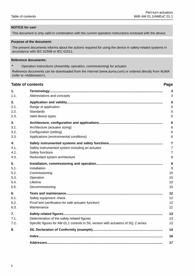
Table of contents Page
31. Terminology............................................................................................................................31.1. Abbreviations and concepts
52. Application and validity.........................................................................................................52.1. Range of application52.2. Standards52.3. Valid device types
63. Architecture, configuration and applications......................................................................63.1. Architecture (actuator sizing)63.2. Configuration (setting)63.3. Applications (environmental conditions)
74. Safety instrumented systems and safety functions...........................................................74.1. Safety instrumented system including an actuator74.2. Safety functions84.3. Redundant system architecture
95. Installation, commissioning and operation.........................................................................95.1. Installation
105.2. Commissioning105.3. Operation105.4. Lifetime105.5. Decommissioning
126. Tests and maintenance..........................................................................................................126.1. Safety equipment: check126.2. Proof test (verification for safe actuator function)126.3. Maintenance
137. Safety-related figures.............................................................................................................137.1. Determination of the safety-related figures137.2. Specific figures for AM 01.1 controls in SIL version with actuators of SQ. 2 series
148. SIL Declaration of Conformity (example).............................................................................
16Index........................................................................................................................................
17Addresses...............................................................................................................................
2
Part-turn actuatorsTable of contents With AM 01.1/AMExC 01.1
1. Terminology
Information sources ● IEC 61508-4, Functional safety of electrical/electronic/programmable electronicsafety-related systems – Part 4: Definitions and abbreviations
● IEC 61511-1, Functional safety - Safety instrumented systems for the processindustry sector – Part 1: Framework, definitions, system, hardware and softwarerequirements
1.1. Abbreviations and concepts
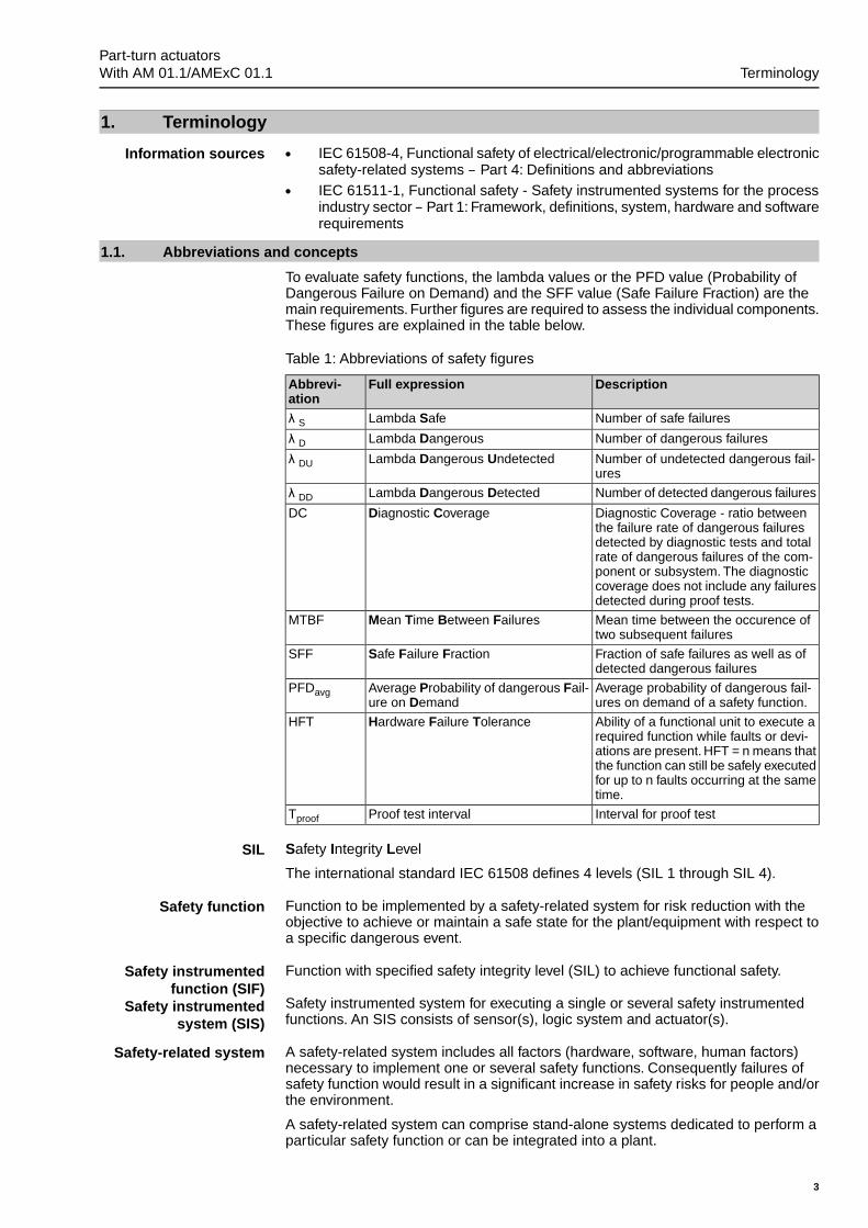
To evaluate safety functions, the lambda values or the PFD value (Probability ofDangerous Failure on Demand) and the SFF value (Safe Failure Fraction) are themain requirements. Further figures are required to assess the individual components.These figures are explained in the table below.
Table 1: Abbreviations of safety figures
DescriptionFull expressionAbbrevi-ation
Number of safe failuresLambda Safeλ S
Number of dangerous failuresLambda Dangerousλ D
Number of undetected dangerous fail-ures
Lambda Dangerous Undetectedλ DU
Number of detected dangerous failuresLambda Dangerous Detectedλ DD
Diagnostic Coverage - ratio betweenthe failure rate of dangerous failuresdetected by diagnostic tests and totalrate of dangerous failures of the com-ponent or subsystem. The diagnosticcoverage does not include any failuresdetected during proof tests.
Diagnostic CoverageDC
Mean time between the occurence oftwo subsequent failures
Mean Time Between FailuresMTBF
Fraction of safe failures as well as ofdetected dangerous failures
Safe Failure FractionSFF
Average probability of dangerous fail-ures on demand of a safety function.
Average Probability of dangerous Fail-ure on Demand
PFDavg
Ability of a functional unit to execute arequired function while faults or devi-ations are present. HFT = n means thatthe function can still be safely executedfor up to n faults occurring at the sametime.
Hardware Failure ToleranceHFT
Interval for proof testProof test intervalTproof
SIL Safety Integrity Level
The international standard IEC 61508 defines 4 levels (SIL 1 through SIL 4).
Safety function Function to be implemented by a safety-related system for risk reduction with theobjective to achieve or maintain a safe state for the plant/equipment with respect toa specific dangerous event.
Safety instrumentedfunction (SIF)
Function with specified safety integrity level (SIL) to achieve functional safety.
Safety instrumentedsystem (SIS)
Safety instrumented system for executing a single or several safety instrumentedfunctions. An SIS consists of sensor(s), logic system and actuator(s).
Safety-related system A safety-related system includes all factors (hardware, software, human factors)necessary to implement one or several safety functions. Consequently failures ofsafety function would result in a significant increase in safety risks for people and/orthe environment.
A safety-related system can comprise stand-alone systems dedicated to perform aparticular safety function or can be integrated into a plant.
3
Part-turn actuators With AM 01.1/AMExC 01.1 Terminology
Proof test Periodic test performed to detect dangerous hidden failures in a safety-related systemso that, if necessary, a repair can restore the system to an "as new" condition or asclose as practical to this condition.
MTTR (Mean Time ToRestoration)
Mean time to restoration once a failure has occurred. Indicates the expected meantime to achieve restoration of the system. It is therefore an important parameter forsystem availability. The time for detecting the failure, planning tasks as well asoperating resources is also included. It should be reduced to a minimum.
4
Part-turn actuatorsTerminology With AM 01.1/AMExC 01.1
2. Application and validity
2.1. Range of application
AUMA actuators and actuator controls with the safety functions mentioned in thismanual are intended for operation of industrial valves and are suitable for use insafety instrumented systems in accordance with IEC 61508 or IEC 61511.
2.2. Standards
Both actuators and actuator controls meet the following requirements:
IEC 61508-2:2010:The safety figures of the devices described meet the requirementsof IEC 61508 in the respective SIL level with regard to failure rates and architecturerequirements. However, this does not imply that all further requirements of IEC 61508are met.
2.3. Valid device types
The data on functional safety contained in this manual applies to the device typesindicated.
Table 2: Overview on suitable device types
Figurestable
ControlType of dutyMotorPower supply
TypeControls
TypeActuator
3OPEN, CLOSES2-15 minS2-30 minS4-25 %S4-50 %
3-phase ACAM 01.1 inSFC version
SQ 05.2 – SQ 14.2SQR 05.2 – SQR 14.2 ESD
OPEN/CLOSESafe STOP(EMERGENCYsignal)
4OPEN, CLOSES2-15 minS2-30 minS4-25 %S4-50 %
3-phase ACAMExC 01.1 inSFC version
SQEx 05.2 – SQEx 14.2SQREx 05.2 – SQREx 14.2 ESD
OPEN/CLOSESafe STOP(EMERGENCYsignal)
Hardware, software and configuration of actuator and actuator controls must not bemodified without prior written consent by AUMA. Unauthorised modification mayhave a negative impact on both safety figures and SIL capability of the products.
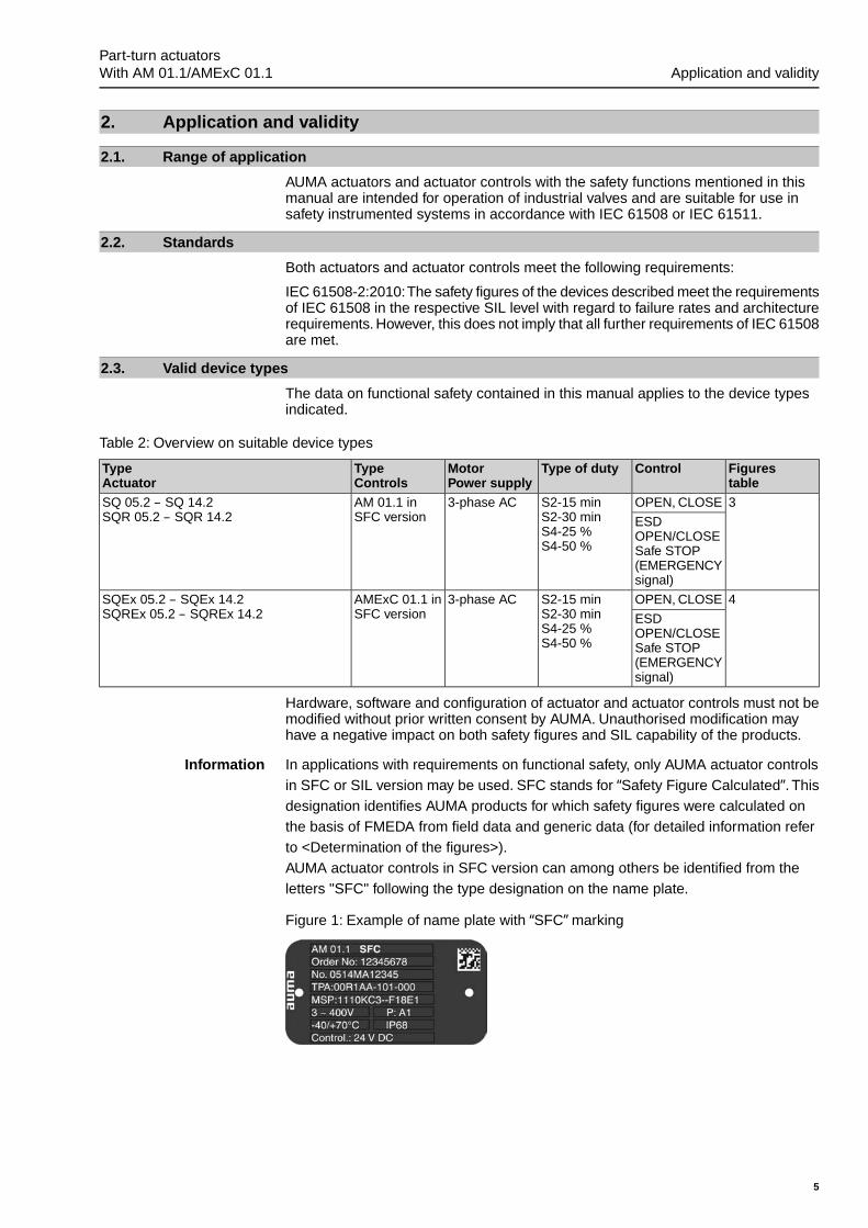
Information In applications with requirements on functional safety, only AUMA actuator controlsin SFC or SIL version may be used. SFC stands for “Safety Figure Calculated”. Thisdesignation identifies AUMA products for which safety figures were calculated onthe basis of FMEDA from field data and generic data (for detailed information referto <Determination of the figures>).AUMA actuator controls in SFC version can among others be identified from theletters "SFC" following the type designation on the name plate.
Figure 1: Example of name plate with “SFC” marking
5
Part-turn actuators With AM 01.1/AMExC 01.1 Application and validity
3. Architecture, configuration and applications
3.1. Architecture (actuator sizing)
For actuator architecture (actuator sizing) the maximum torques, running torquesand operating times are taken into consideration.
Incorrect actuator architecture can lead to device damage within the safety-related system!
Possible consequences can be valve damage, motor overheating, contactor jamming,defective thyristors, heating up or damage to cables.
→ The actuator technical data must imperatively be observed when selecting theactuator.
→ Sufficient reserves have to be provided to ensure that actuators are capable ofreliably opening or closing the valve even in the event of an accident or under-voltage.
Information The seating type of the EMERGENCY function always complies with the seatingtype of the normal operation function. For "forced limit seating in end position", theseating is performed via limit switches in the end position. Since these elementshave an unavoidable hysteresis, the actuator slightly leaves the end position beforethe end position signal is deleted. Consequently, there is a marginal range of actuatorpositions to the safety position, for which the end position is still signalled althoughthe actuator has already left the end position during operation from safety position.Within this range, triggering the ESD function (Safe OPENING or CLOSING) resultsin standstill of the actuator. If the range in question is approached from the oppositedirection, this limitation does not apply. In general this range is relatively small.However, for unfavourable configurations, this range can amount to more than 10% of the total swivel movement.Should within the framework of unfavourable conditions the effect described aboverepresent an unacceptable limitation for the safety function, we recommend usingboth actuator and actuator controls in configuration "forced torque seating in endposition".
3.2. Configuration (setting)
Configuration (setting) of the safety-related functions is performed as described inthe operation instructions or in the present manual (functional safety).
3.3. Applications (environmental conditions)
When specifying and using the actuators within safety instrumented systems, makesure that the permissible service conditions and the EMC requirements by theperipheral devices are met. Service conditions are indicated in the technical datasheets:
● Enclosure protection● Corrosion protection● Ambient temperature● Vibration resistanceIf the actual ambient temperatures exceed an average of +40 °C, the lambda valueshave to be incremented by a safety factor. For an average temperature of +60 °C,this factor is specified to 2.5.
6
Part-turn actuatorsArchitecture, configuration and applications With AM 01.1/AMExC 01.1
4. Safety instrumented systems and safety functions
4.1. Safety instrumented system including an actuator
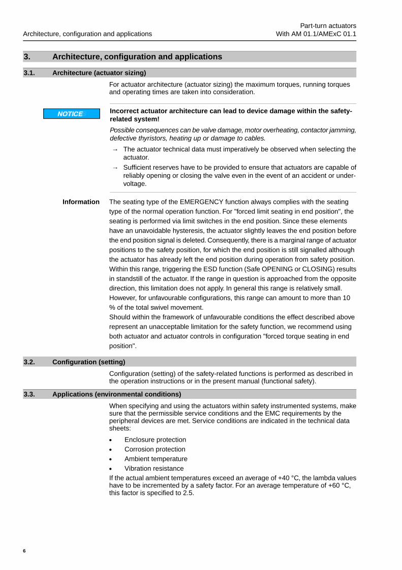
Typically, a safety instrumented system including an actuator is composed of thecomponents as shown in the figure.
Figure 2: Typical safety instrumented system
[1] Sensors[2] Controls (standard and safety PLC)[3] Actuator with actuator controls[4] Valve[5] Process control system
The safety integrity level is always assigned to an overall safety instrumented systemand not to an individual component.
For an individual component (e.g. an actuator), safety figures are determined.Thesefigures are used to assign the devices to a potential safety integrity level (SIL). Thefinal classification of the safety instrumented system can only be made after assessingand calculating all subsystems.
4.2. Safety functions
To determine the SIL figures, the safety function of the device (function which hasto be performed in case of an emergency to operate the plant into a safe state) hasto be considered.
In calculating the safety figures of actuators, the following safety functions are takeninto account:
7
Part-turn actuators With AM 01.1/AMExC 01.1 Safety instrumented systems and safety functions
● ESD function (Emergency Shut Down): Safe OPENING/CLOSING with reactionmonitoring- A signal (standard: low active) causes the actuator to travel into the con-
figured direction (OPEN/CLOSE).
● STOP function: safe standstill/stop- An operation command (in directions OPEN or CLOSE) will only be ex-
ecuted if no STOP command is applied.
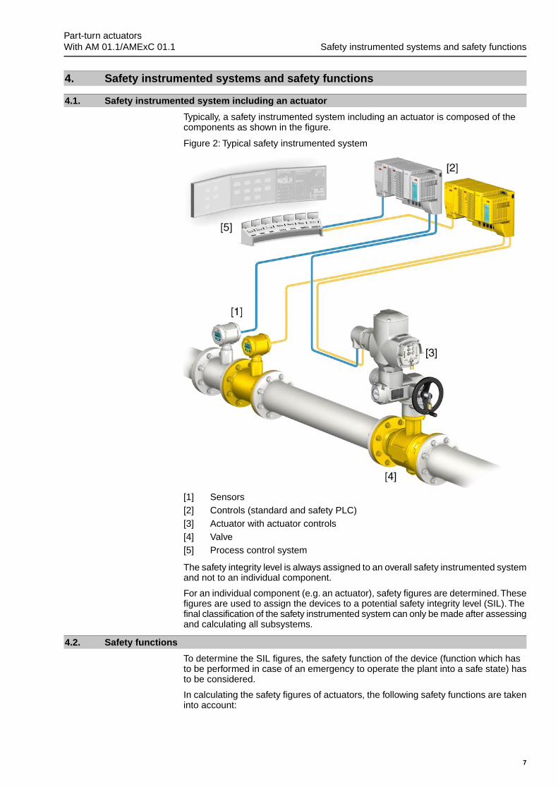
4.3. Redundant system architecture
Besides the already described typical safety instrumented system including anactuator, safety can be increased by integrating a second, redundant valve andactuator with actuator controls into the safety instrumented system. The decision onthe correct version depends on the entire system.
Figure 3: Redundant system with ESD for Safe CLOSING
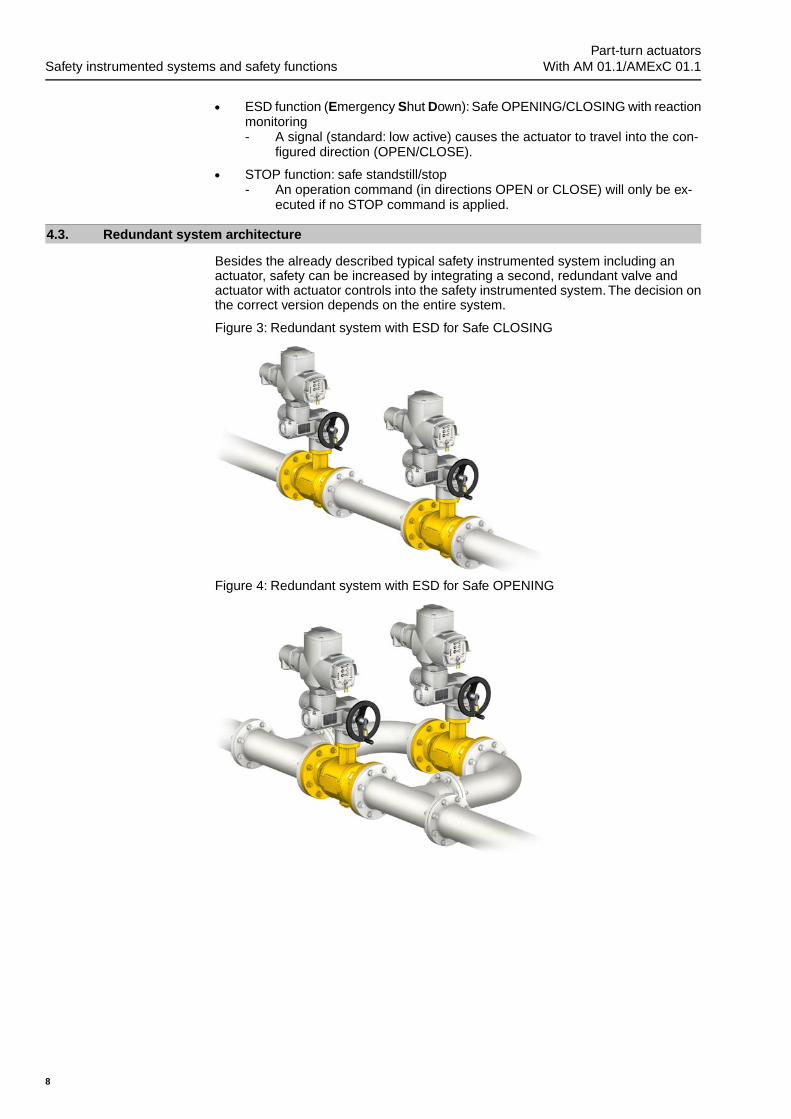
Figure 4: Redundant system with ESD for Safe OPENING
8
Part-turn actuatorsSafety instrumented systems and safety functions With AM 01.1/AMExC 01.1
5. Installation, commissioning and operation
Information Installation and commissioning have to be documented by means of an assemblyreport and an inspection certificate. Installation may only be performed by authorisedpersonnel who have been trained on functional safety.
5.1. Installation
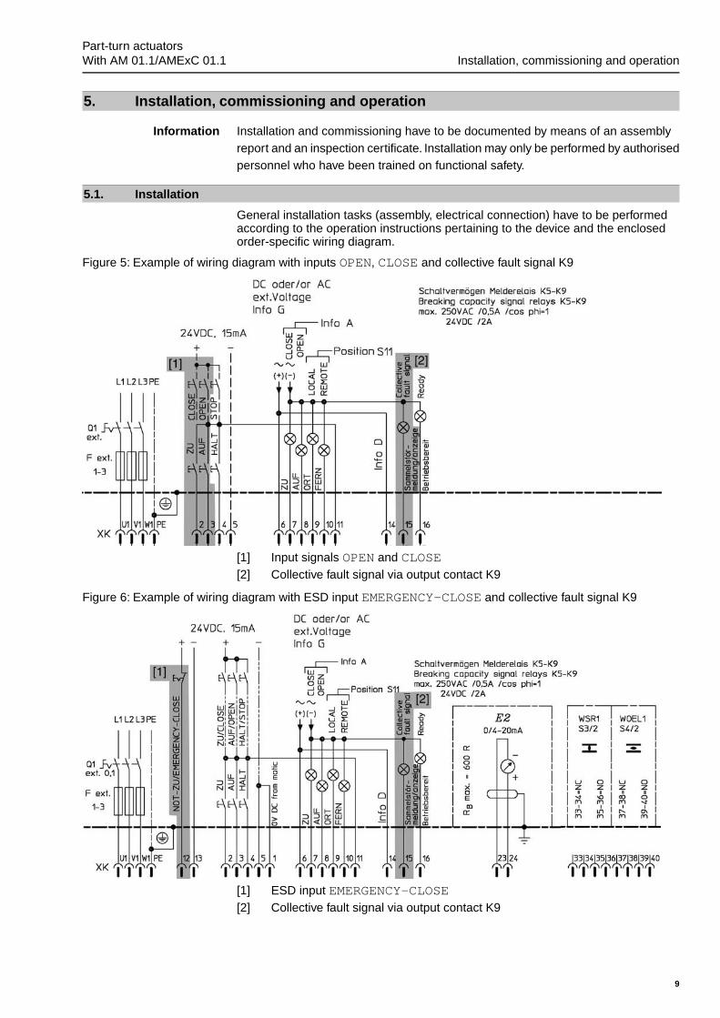
General installation tasks (assembly, electrical connection) have to be performedaccording to the operation instructions pertaining to the device and the enclosedorder-specific wiring diagram.
Figure 5: Example of wiring diagram with inputs OPEN, CLOSE and collective fault signal K9
[1] Input signals OPEN and CLOSE[2] Collective fault signal via output contact K9
Figure 6: Example of wiring diagram with ESD input EMERGENCY-CLOSE and collective fault signal K9
[1] ESD input EMERGENCY-CLOSE[2] Collective fault signal via output contact K9
9
Part-turn actuators With AM 01.1/AMExC 01.1 Installation, commissioning and operation
● For AUMA MATIC in SFC version with ESD function (Safe OPENING/CLOSING),operation to safe position via inputs OPEN and CLOSE is only possible if theselector switch is in position Remote control (REMOTE). We recommendlocking the selector switch in position REMOTE to prevent unauthorised opera-tion. Limit switches, torque switches and thermoswitches are active.In this case, evaluation of the REMOTE signal can be useful for assessing theavailability of the ESD function.
● For AUMA MATIC in SFC version with ESD function (Safe OPENING/CLOSING)via ESD input EMERGENCY , the actuator will be operated to the safe positionif requested and irrespective of the selector switch position. For the ESD func-tion, the safe position (OPEN or CLOSED) has to be set in the factory.
● For AUMA actuators with AUMA MATIC actuator controls the STOP signal al-ways has priority. It also overrides the EMERGENCY input
● A signal is issued via collective fault K9 once thermal protection or torqueswitches trip. This fault signal must imperatively be evaluated by the safetyPLC. In the event of a fault signal, the actuator must immediately be inspectedand repaired, if required.
● If either thermal protection or the torque switch trips, the ESD function will notbe available (Safe OPENING/CLOSING).
● For versions with ESD function (Safe OPENING/CLOSING), 3-phase powersupply has to be provided. During phase failure or in the event of undervoltage,an alarm is also displayed via the fault output contact. The mid-position LEDon the local controls of the AUMA MATIC actuator controls in SFC version isilluminated according to configuration.
Information ● Valve position indication is made via potentiometer or 4 – 20 mA signals.However, these factors are not part of the determination of safety figures.
5.2. Commissioning
The operation instructions pertaining to the device must be observed for generalcommissioning.
Risk of immediate actuator operation when switching on!
Risk of personal injuries or damage to the valve
→ Ensure that ESD (EMERGENCY) input signal is applied in compliance with theconfiguration when switching on.
After commissioning, the safe actuator function must be verified.
5.3. Operation
Regular maintenance and device checks in the Tproof intervals as defined by theplant operator are the basis for safe operation.
The operation instructions pertaining to the device must be observed for operation.
5.4. Lifetime
Actuator lifetime is described in the technical data sheets or the operation instructions.
Safety-related figures are valid for the cycles or modulating steps defined in thetechnical data specifications and for typical periods of up to 10 years (the criterionachieved first is valid). After this period, the probability of failure increases.
5.5. Decommissioning
When decommissioning an actuator with safety functions, the following must beobserved:
● Impact of decommissioning on relevant devices, equipment or other work mustbe evaluated.
● Safety and warning instructions contained in the actuator operation instructionsmust be met.
10
Part-turn actuatorsInstallation, commissioning and operation With AM 01.1/AMExC 01.1
● Decommissioning must be carried out exclusively by suitably qualified personnel.● Decommissioning must be recorded in compliance with regular requirements.
11
Part-turn actuators With AM 01.1/AMExC 01.1 Installation, commissioning and operation
6. Tests and maintenanceTest and maintenance tasks may only be performed by authorised personnel whohave been trained on functional safety.
Test and maintenance equipment has to be calibrated.
Information Any test/maintenance must be recorded in a test/maintenance report.
Impact of testing/maintenance on relevant devices, equipment or other work mustbe evaluated.
6.1. Safety equipment: check
All safety functions within a safety equipment must be checked for perfect functionalityand safety at appropriate intervals. The intervals for safety equipment checks are tobe defined by the plant operator.
The plant operator has to establish a safety planning for the entire safety lifecycleof the SIS. Policies and strategies for achieving safety as well as different activitiesduring the safety life cycle should be defined.
6.2. Proof test (verification for safe actuator function)
The proof test serves the purpose to verify the safety-related functions of the actuatorand actuator controls.
Proof tests shall reveal dangerous faults which might be undetected until a safetyfunction is started and consequently result in a potential danger.
The safety-related OPEN/CLOSE/EMERGENCY signal input is appropriately assignedto check the safety-relevant function. As a consequence, the actuator must performthe safety function without fault indication at output contact K9.
Check list for verification and validation of safety functions:● Has running in direction OPEN via input OPEN been performed?● Has running in direction CLOSE via input CLOSE been performed?● Has ESD EMERGENCY input (if available) via input been checked?● Has collective fault output contact (K9) been verified?The collective fault output contact can be activated via manual torque switch testusing the test buttons. Refer to the relevant chapter in the actuator operationinstructions.
Intervals:
A proof test interval describes the time between two proof tests. Functionality mustbe checked in appropriate intervals. The intervals are to be defined by the plantoperator.
In any case, the safety-relevant functions must be checked after commissioning andfollowing any maintenance work or repair as well as during the Tproof intervals definedin safety assessment.
6.3. Maintenance
Maintenance and service tasks may only be performed by authorised personnel whohave been trained on functional safety (refer to chapter 5).
Once maintenance and service tasks have been finished, the functional test mustbe completed by a validating process of the safety function including at least thetests described in the <Safety equipment: check> and <Proof test (verification ofsafe actuator function)> chapters.
In case a fault is detected during maintenance, this must be reported to AUMA RiesterGmbH & Co. KG.
Information AUMA actuators prioritise motor operation to manual operation.This means that theactuator automatically switches to motor operation if requested. However, we recom-mend activating motor operation after any maintenance and service interventions.
12
Part-turn actuatorsTests and maintenance With AM 01.1/AMExC 01.1
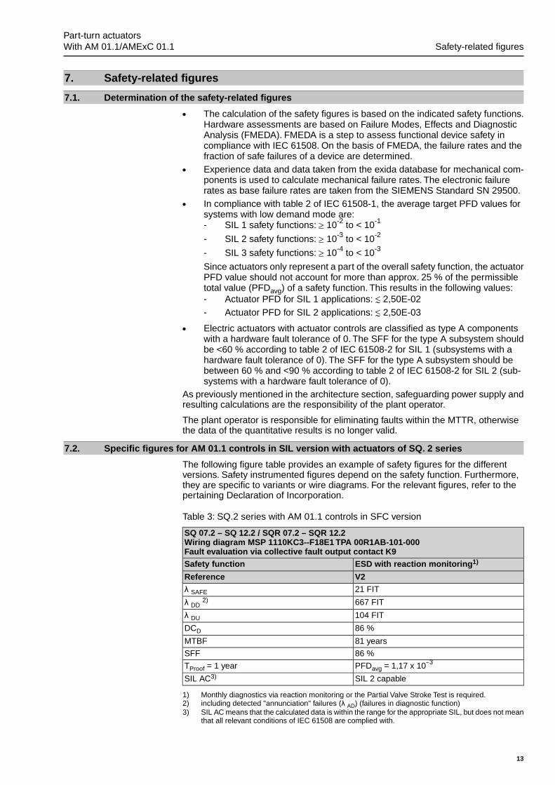
7. Safety-related figures
7.1. Determination of the safety-related figures
● The calculation of the safety figures is based on the indicated safety functions.Hardware assessments are based on Failure Modes, Effects and DiagnosticAnalysis (FMEDA). FMEDA is a step to assess functional device safety incompliance with IEC 61508. On the basis of FMEDA, the failure rates and thefraction of safe failures of a device are determined.
● Experience data and data taken from the exida database for mechanical com-ponents is used to calculate mechanical failure rates. The electronic failurerates as base failure rates are taken from the SIEMENS Standard SN 29500.
● In compliance with table 2 of IEC 61508-1, the average target PFD values forsystems with low demand mode are:- SIL 1 safety functions: ≥ 10-2 to < 10-1
- SIL 2 safety functions: ≥ 10-3 to < 10-2
- SIL 3 safety functions: ≥ 10-4 to < 10-3
Since actuators only represent a part of the overall safety function, the actuatorPFD value should not account for more than approx. 25 % of the permissibletotal value (PFDavg) of a safety function. This results in the following values:- Actuator PFD for SIL 1 applications: ≲ 2,50E-02- Actuator PFD for SIL 2 applications: ≲ 2,50E-03
● Electric actuators with actuator controls are classified as type A componentswith a hardware fault tolerance of 0. The SFF for the type A subsystem shouldbe <60 % according to table 2 of IEC 61508-2 for SIL 1 (subsystems with ahardware fault tolerance of 0). The SFF for the type A subsystem should bebetween 60 % and <90 % according to table 2 of IEC 61508-2 for SIL 2 (sub-systems with a hardware fault tolerance of 0).
As previously mentioned in the architecture section, safeguarding power supply andresulting calculations are the responsibility of the plant operator.
The plant operator is responsible for eliminating faults within the MTTR, otherwisethe data of the quantitative results is no longer valid.
7.2. Specific figures for AM 01.1 controls in SIL version with actuators of SQ. 2 series
The following figure table provides an example of safety figures for the differentversions. Safety instrumented figures depend on the safety function. Furthermore,they are specific to variants or wire diagrams. For the relevant figures, refer to thepertaining Declaration of Incorporation.
Table 3: SQ.2 series with AM 01.1 controls in SFC version
SQ 07.2 – SQ 12.2 / SQR 07.2 – SQR 12.2Wiring diagram MSP 1110KC3--F18E1 TPA 00R1AB-101-000Fault evaluation via collective fault output contact K9
ESD with reaction monitoring1)Safety function
V2Reference21 FITλ SAFE
667 FITλ DD2)
104 FITλ DU
86 %DCD
81 yearsMTBF
86 %SFF
PFDavg = 1,17 x 10⁻³TProof = 1 year
SIL 2 capableSIL AC3)
Monthly diagnostics via reaction monitoring or the Partial Valve Stroke Test is required.1)including detected "annunciation" failures (λ AD) (failures in diagnostic function)2)SIL AC means that the calculated data is within the range for the appropriate SIL, but does not meanthat all relevant conditions of IEC 61508 are complied with.
3)
13
Part-turn actuators With AM 01.1/AMExC 01.1 Safety-related figures
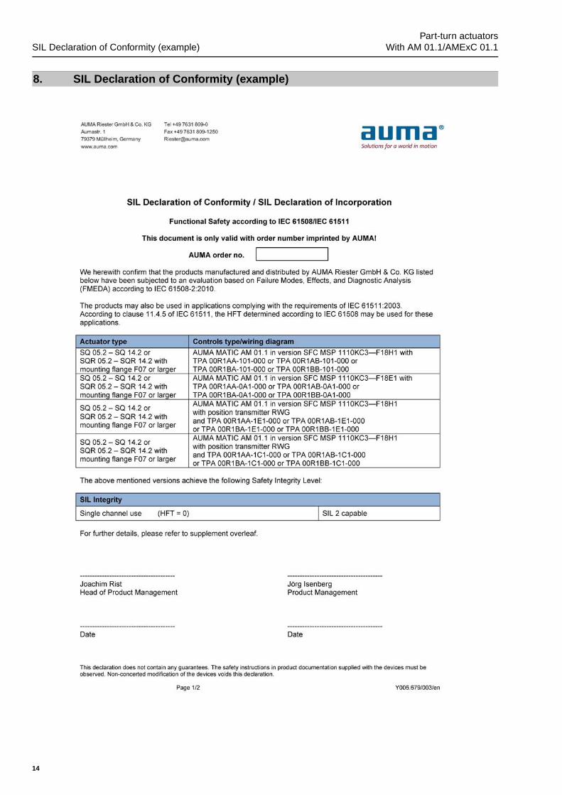
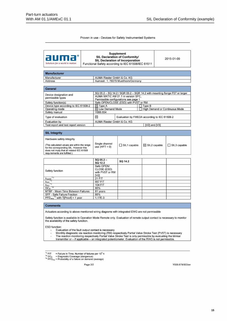
8. SIL Declaration of Conformity (example)
14
Part-turn actuatorsSIL Declaration of Conformity (example) With AM 01.1/AMExC 01.1
15
Part-turn actuators With AM 01.1/AMExC 01.1 SIL Declaration of Conformity (example)
Index
AActuator definition 6Ambient conditions 6Architecture 6
CCommissioning 10Configuration 6
DDC 3Declaration of Conformity 14Decommissioning 10Device types 5Diagnostic coverage (DC) 3
FFigures, safety-related 13
HHFT 3
IInstallation 9Interval for proof test 3
LLambda values 3 , 13Lifetime 10Low Demand Mode 13
MMaintenance 12Mean Time Between Failures(MTBF)
3
MTBF 3MTTR (Mean Time To Restor-ation)
4
OOperation 10
PPFD 3PFD for actuator 13Probability of failure 3 , 10Proof test 4 , 12 , 12
RRange of application 5
SSafe failure fraction (SFF) 3 , 13Safety function 3Safety functions 7Safety instrumented function(SIF)
3
Safety instrumented system 7Safety instrumented system(SIS)
3
Safety-related system 3Service conditions 6Setting 6SFF 3SIL 3Standards 5
TTests 12T proof 3
16
Part-turn actuatorsIndex With AM 01.1/AMExC 01.1
Europe
AUMA Riester GmbH & Co. KG
Plant MüllheimDE 79373 MüllheimTel +49 7631 809 - [email protected]
Plant Ostfildern-NellingenDE 73747 OstfildernTel +49 711 34803 - [email protected]
Service-Center BayernDE 85386 EchingTel +49 81 65 9017- [email protected]
Service-Center KölnDE 50858 KölnTel +49 2234 2037 - [email protected]
Service-Center MagdeburgDE 39167 NiederndodelebenTel +49 39204 759 - [email protected]
AUMA-Armaturenantriebe Ges.m.b.H.AT 2512 TribuswinkelTel +43 2252 [email protected]
AUMA BENELUX B.V. B. A.BE 8800 RoeselareTel +32 51 24 24 [email protected]
ProStream Group Ltd.BG 1632 SofiaTel +359 2 [email protected]
OOO “Dunkan-Privod”BY 220004 MinskTel +375 29 [email protected]
AUMA (Schweiz) AGCH 8965 BerikonTel +41 566 [email protected]
AUMA Servopohony spol. s.r.o.CZ 250 01 Brandýs n.L.-St.BoleslavTel +420 326 396 [email protected]
GRØNBECH & SØNNER A/SDK 2450 København SVTel +45 33 26 63 [email protected]
IBEROPLAN S.A.ES 28027 MadridTel +34 91 [email protected]
AUMA Finland OyFI 02230 EspooTel +358 9 5840 [email protected]
AUMA France S.A.R.L.FR 95157 Taverny CedexTel +33 1 [email protected]
AUMA ACTUATORS Ltd.GB Clevedon, North Somerset BS21 6THTel +44 1275 [email protected]
D. G. Bellos & Co. O.E.GR 13673 Acharnai, AthensTel +30 210 [email protected]
APIS CENTAR d. o. o.HR 10437 BestovjeTel +385 1 6531 [email protected]
Fabo Kereskedelmi és Szolgáltató Kft.HU 8800 NagykanizsaTel +36 93/[email protected]
Falkinn HFIS 108 ReykjavikTel +00354 540 [email protected]
AUMA ITALIANA S.r.l. a socio unicoIT 20023 Cerro Maggiore (MI)Tel +39 0331 [email protected]
AUMA BENELUX B.V.LU Leiden (NL)Tel +31 71 581 40 [email protected]
NB Engineering ServicesMT ZBR 08 ZabbarTel + 356 2169 [email protected]
AUMA BENELUX B.V.NL 2314 XT LeidenTel +31 71 581 40 [email protected]
SIGUM A. S.NO 1338 SandvikaTel +47 [email protected]
AUMA Polska Sp. z o.o.PL 41-219 SosnowiecTel +48 32 783 52 [email protected]
AUMA-LUSA Representative Office, Lda.PT 2730-033 BarcarenaTel +351 211 307 [email protected]
SAUTECHRO 011783 BucurestiTel +40 372 [email protected]
OOO PRIWODY AUMARU 141402 Khimki, Moscow regionTel +7 495 221 64 [email protected]
OOO PRIWODY AUMARU 125362 MoscowTel +7 495 787 78 [email protected]
ERICHS ARMATUR ABSE 20039 MalmöTel +46 40 [email protected]
ELSO-b, s.r.o.SK 94901 NitraTel +421 905/[email protected]
Auma Endüstri Kontrol Sistemleri LimitedSirketiTR 06810 AnkaraTel +90 312 217 32 [email protected]
AUMA Technology Automations LtdUA 02099 KievTel +38 044 [email protected]
Africa
Solution Technique Contrôle CommandeDZ Bir Mourad Rais, AlgiersTel +213 21 56 42 09/[email protected]
A.T.E.C.EG CairoTel +20 2 23599680 - [email protected]
SAMIREGMA 203000 CasablancaTel +212 5 22 40 09 [email protected]
MANZ INCORPORATED LTD.NG Port HarcourtTel [email protected]
17
AUMA worldwide
AUMA South Africa (Pty) Ltd.ZA 1560 SpringsTel +27 11 [email protected]
America
AUMA Argentina Rep.OfficeAR Buenos AiresTel +54 11 4737 [email protected]
AUMA Automação do Brazil ltda.BR Sao PauloTel +55 11 [email protected]
TROY-ONTOR Inc.CA L4N 8X1 Barrie, OntarioTel +1 705 [email protected]
AUMA Chile Representative OfficeCL 9500414 BuinTel +56 2 821 [email protected]
Ferrostaal de Colombia Ltda.CO Bogotá D.C.Tel +57 1 401 [email protected]
Transcontinental Trading Overseas SA.CU Ciudad HabanaTel +53 7 208 9603 / 208 [email protected]
AUMA Región Andina & CentroaméricaEC QuitoTel +593 2 245 [email protected]
Corsusa International S.A.C.PE Miraflores - LimaTel +511444-1200 / 0044 / [email protected]
Control Technologies LimitedTT Marabella,Trinidad, W.I.Tel + 1 868 658 1744/5011www.ctltech.com
AUMA ACTUATORS INC.US PA 15317 CanonsburgTel +1 724-743-AUMA (2862)[email protected]
SuplibarcaVE Maracaibo, Estado, ZuliaTel +58 261 7 555 [email protected]
Asia
AUMA Actuators UAE Support OfficeAE 287 Abu DhabiTel +971 [email protected]
AUMA Actuators Middle EastBH 152 68 SalmabadTel +97 3 [email protected]
Mikuni (B) Sdn. Bhd.BN KA1189 Kuala BelaitTel + 673 3331269 / [email protected]
AUMA Actuators (China) Co., LtdCN 215499 TaicangTel +86 512 3302 [email protected]
PERFECT CONTROLS Ltd.HK Tsuen Wan, KowloonTel +852 2493 [email protected]
PT. Carakamas Inti AlamID 11460 JakartaTel +62 [email protected]
AUMA INDIA PRIVATE LIMITED.IN 560 058 BangaloreTel +91 80 2839 [email protected]
ITG - Iranians Torque GeneratorIR 13998-34411 [email protected]
Trans-Jordan Electro Mechanical SuppliesJO 11133 AmmanTel +962 - 6 - [email protected]
AUMA JAPAN Co., Ltd.JP 211-0016 Kawasaki-shi, KanagawaTel +81-(0)[email protected]
DW Controls Co., Ltd.KR 153-702 Gasan-dong, GeumChun-Gu,,SeoulTel +82 2 2624 [email protected]
Al-Arfaj Engineering Co WLLKW 22004 SalmiyahTel [email protected]
TOO “Armaturny Center”KZ 060005 AtyrauTel +7 7122 454 [email protected]
Network EngineeringLB 4501 7401 JBEIL, BeirutTel +961 9 [email protected]
AUMA Malaysia OfficeMY 70300 Seremban, Negeri SembilanTel +606 633 [email protected]
Mustafa Sultan Science & Industry Co LLCOM RuwiTel +968 24 [email protected]
FLOWTORK TECHNOLOGIESCORPORATIONPH 1550 Mandaluyong CityTel +63 2 532 [email protected]
M & C Group of CompaniesPK 54000 Cavalry Ground, Lahore CanttTel +92 42 3665 0542, +92 42 3668 [email protected]
Petrogulf W.L.LQA DohaTel +974 [email protected]
AUMA Saudi Arabia Support OfficeSA 31952 Al KhobarTel + 966 5 5359 [email protected]
AUMA ACTUATORS (Singapore) Pte Ltd.SG 569551 SingaporeTel +65 6 [email protected]
NETWORK ENGINEERINGSY Homs+963 31 231 [email protected]
Sunny Valves and Intertrade Corp. Ltd.TH 10120 Yannawa, BangkokTel +66 2 [email protected]
Top Advance Enterprises Ltd.TW Jhonghe City,Taipei Hsien (235)Tel +886 2 2225 [email protected]
AUMA Vietnam Hanoi ROVN Hanoi+84 4 [email protected]
Australia
BARRON GJM Pty. Ltd.AU NSW 1570 ArtarmonTel +61 2 8437 [email protected]
18
AUMA worldwide

19
AUMA worldwide
AUMA Riester GmbH & Co. KG
P.O.Box 1362DE 79373 MuellheimTel +49 7631 809 - 0Fax +49 7631 809 - [email protected]
Y006.654/003/en/1.15
For detailed information on AUMA products, refer to the Internet: www.auma.com